EP2819945B1 - Perforation device to perforate closed receptacles containing coloring products - Google Patents
Perforation device to perforate closed receptacles containing coloring products Download PDFInfo
- Publication number
- EP2819945B1 EP2819945B1 EP13720007.7A EP13720007A EP2819945B1 EP 2819945 B1 EP2819945 B1 EP 2819945B1 EP 13720007 A EP13720007 A EP 13720007A EP 2819945 B1 EP2819945 B1 EP 2819945B1
- Authority
- EP
- European Patent Office
- Prior art keywords
- support plane
- plate
- perforation
- receptacle
- pedal
- Prior art date
- Legal status (The legal status is an assumption and is not a legal conclusion. Google has not performed a legal analysis and makes no representation as to the accuracy of the status listed.)
- Not-in-force
Links
Images



Classifications
-
- B—PERFORMING OPERATIONS; TRANSPORTING
- B67—OPENING, CLOSING OR CLEANING BOTTLES, JARS OR SIMILAR CONTAINERS; LIQUID HANDLING
- B67B—APPLYING CLOSURE MEMBERS TO BOTTLES JARS, OR SIMILAR CONTAINERS; OPENING CLOSED CONTAINERS
- B67B7/00—Hand- or power-operated devices for opening closed containers
- B67B7/24—Hole-piercing devices
-
- B—PERFORMING OPERATIONS; TRANSPORTING
- B65—CONVEYING; PACKING; STORING; HANDLING THIN OR FILAMENTARY MATERIAL
- B65B—MACHINES, APPARATUS OR DEVICES FOR, OR METHODS OF, PACKAGING ARTICLES OR MATERIALS; UNPACKING
- B65B69/00—Unpacking of articles or materials, not otherwise provided for
- B65B69/0033—Unpacking of articles or materials, not otherwise provided for by cutting
- B65B69/0041—Unpacking of articles or materials, not otherwise provided for by cutting by puncturing
-
- F—MECHANICAL ENGINEERING; LIGHTING; HEATING; WEAPONS; BLASTING
- F16—ENGINEERING ELEMENTS AND UNITS; GENERAL MEASURES FOR PRODUCING AND MAINTAINING EFFECTIVE FUNCTIONING OF MACHINES OR INSTALLATIONS; THERMAL INSULATION IN GENERAL
- F16P—SAFETY DEVICES IN GENERAL; SAFETY DEVICES FOR PRESSES
- F16P3/00—Safety devices acting in conjunction with the control or operation of a machine; Control arrangements requiring the simultaneous use of two or more parts of the body
- F16P3/18—Control arrangements requiring the use of both hands
Definitions
- the present invention concerns a mechanical perforation device, able to be selectively actuated by means of a pedal, so as to perforate, one at a time, closed receptacles, such as for example metal containers, of any shape and size, containing coloring products, such as coloring liquids or powders, bases for paints, varnishes, enamels, inks or similar products.
- the device according to the present invention is applied particularly in dispensing machines, or dispensers, of coloring products, able to introduce a dosed quantity of coloring pigments into a receptacle containing a paint base, to obtain the desired coloring product.
- Machines are known for dispensing coloring products, such as for example pigments, into a receptacle that contains a fluid paint base, to obtain in this way a coloring product with a desired shade.
- coloring products such as for example pigments
- One of such machines is described in the Italian patent of industrial invention n. 1.279.712, granted to the present Applicant on 16.12.1997 .
- the receptacle is disposed on a support plane, able to be lifted vertically by means of an electric motor controlled by a computerized control unit.
- the support plane on which the receptacle to be perforated and containing the paint base is positioned is lifted toward a shaped punch disposed at a determinate height, until the latter perforates the upper wall of the receptacle.
- the support plane is then taken to a delivery position, lower than the perforation position, and kept in the position reached until the step of delivering the colored pigments is complete, through one or more delivery nozzles.
- the perforation device of the receptacle is therefore commanded electrically, with all the disadvantages deriving therefrom, including the production and functioning costs, in addition to the fact that it is impossible to use when there is no electric energy.
- Document GB-A-2.048.825 describes a perforation device for containers that shows the characteristics of the preamble of the main claim.
- Purpose of the present invention is to obtain a device to perforate closed receptacles, for example metal, and containing coloring products, which is simple, economical to construct and reliable, and which has no running costs.
- the Applicant has devised, tested and embodied the present invention to overcome the shortcomings of the state of the art and to obtain these and other purposes and advantages.
- a perforation device for perforating closed receptacles containing coloring products, comprises a support plane movable in a substantially vertical direction and on which a receptacle to be perforated is suitable to be disposed, a perforation member disposed at a determinate height, higher than the support plane, and actuation means to selectively move the latter toward the perforation member to cause the perforation of the receptacle to be perforated.
- the perforation member may comprise, for example, any punch provided with shaped blades.
- the actuation means comprise a lifting mechanism connected to the support plane and drivable by means of a pedal.
- the lifting mechanism comprises a cable having a first end attached to the pedal and a second end attached to a plate able to slide vertically, on which the support plane is mounted, so that the actuation of the pedal by an operator lifts both the plate and the support plane toward the perforation member.
- the plate is able to slide with respect to a vertical frame, on which a fixed pulley is mounted rotatable, on which the cable is disposed.
- the frame comprises two uprights disposed on opposite sides with respect to the plate and on which the support plane is able to slide vertically.
- the support plane can also be positioned at different heights with respect to the plate, using vertical positioning means, in order to be selectively positioned at a determinate distance from the perforation member, depending on the height of the receptacle to be perforated.
- a safety mechanism is provided to be manually driven, so that the pedal cannot be driven by the operator without the latter also driving the safety mechanism at the same time and with both hands.
- the safety mechanism comprises two hooks normally held attached to the plate by elastic means to hold the plate normally clamped in a lowered position. Furthermore, each of the hooks is mechanically connected to a release element which can be actuated manually, for example by means of a cable.
- an operator can first position the support plane at a desired height, that is, a desired distance from the perforation member, depending on the height of the receptacle to be perforated, making the support plane slide with respect to the actuation means, and then, after actuating the safety mechanism, drive the pedal and perform the perforation proper; all this in total safety, with no cost whatsoever and without needing to have available any source of energy other than the physical energy supplied by the operator himself.
- a perforation device 10 is shown mounted on a machine 11 for preparing and dispensing coloring products, contained in closed containers 12, for example metal, one of which is shown, by way of example, in fig. 3 .
- the machine 11 can be of any known type, for example like the one described in the Italian patent of industrial invention n. 1.279.712, cited above, or any that might be developed in the future.
- the perforation device 10 comprises a frame 15 ( figs. 1 and 2 ), which is attached to a support structure 16 of the machine 11.
- a perforation member 18 is mounted on the frame 15 at a determinate height from the base.
- the perforation member 18 is also of the known type, for example with blades, shaped so as to perforate the upper part or lid of the receptacle 12, making a hole on it with a diameter suitable to allow the delivery of coloring products inside the receptacle 12.
- An example of how the perforation member 18 can be made is described in the Italian patent of industrial invention n. 1.279.712, cited above.
- a support plane 21 is mounted cantilevered on the plate 20, on the upper surface of which support plane 21 a receptacle 12 is able to be positioned.
- the support plane 21 is mounted sliding vertically on two uprights 22 of the frame 15, distanced and lateral with respect to the plate 20, and can also be adjusted in height with respect to the latter, depending on the height of the receptacle 12 to be perforated.
- the support plane 21 is provided with a clamping peg 25 ( fig. 5 ) which is normally held by a helical spring 26 inside one of the holes of a first plurality of holes 27 in the plate 20 and aligned vertically ( fig. 1 ) substantially at the center thereof.
- the interaxis between two adjacent holes 27 is for example about 15 mm.
- a knob 28 ( figs. 1 to 5 ) is attached at the end of the clamping peg 25 opposite the end inserted in one of the holes 27 and is drivable manually to temporarily release the clamping peg 25, making it slide axially against the action of the helical spring 26.
- the support plane 21 can be raised or lowered manually and thus positioned at the desired height with respect to the plate 20, so that when the receptacle 12 to be perforated is positioned on the support plane 21, the upper part of the receptacle 12 is at a distance of about 10 mm to about 20 mm from the lower end of the perforation member 18.
- the plate 20 and the support plane 21 associated therewith can be raised selectively toward the perforation member 18 by means of a lifting mechanism 29, which comprises a pedal 30 attached to an external end 31 of a lever 32 formed by two arms 33, parallel to each other, the lever 32 being pivoted with an internal end 34 to a pin 35 of the frame 15.
- a lifting mechanism 29 which comprises a pedal 30 attached to an external end 31 of a lever 32 formed by two arms 33, parallel to each other, the lever 32 being pivoted with an internal end 34 to a pin 35 of the frame 15.
- the two arms 33 of the lever 32 are inserted with play in two vertical slits 37 made in the lower part of the plate 20.
- One end of a cable 36 is attached to the two arms 33 of the lever 32 in an intermediate point between the ends 31 and 34, behind the plate 20, by means of a fork 38 ( fig. 6 ).
- the opposite end of the cable 36 is attached in the upper part of the plate 20.
- the cable 36 passes on a fixed pulley 39 rotatably supported by the frame 15.
- the lever 32 In the inactive condition, the lever 32 is substantially horizontal ( figs. 1 to 4 ), held in said position at least by the weight of the plate 20 itself, or by a return spring not shown in the drawings, and of the support plane 21. Furthermore, in this position, the arms 33 of the lever 32 are disposed in the upper part of the slits 37 of the plate 20.
- the perforation device 10 also comprises a safety mechanism 40, which in turn comprises two hooks 42 ( figs. 2 , 3 , 4 and 8 ), pivoted in the lower part of the frame 15 and held constantly thrust by helical springs 43 inside corresponding holes 45 made in the lower part of the plate 20, between the slits 37.
- the holes 45 are disposed on two vertical rows, adjacent and distanced from each other by about 8 mm, and have a vertical interaxis of about 12 mm.
- the two hooks 42 normally hold the plate 20 and the associated support plane 21 clamped in an inactive position; they must be released simultaneously to allow to drive the pedal 30 and to lift the support plane 21 toward the perforation member 18.
- the safety mechanism 40 also comprises two actuation elements 46, able to be actuated manually and independently, to make the two hooks 42 rotate in an anti-clockwise direction ( fig. 8 ) and take them out of the corresponding holes 45 of the plate 20, against the action of the helical springs 43.
- each actuation element 46 comprises a button 47 disposed above the perforation member 18 and on opposite sides with respect to a vertical axis passing through the perforation member 18 and connected to the corresponding hook 42 by a connecting tie rod 49.
- the lower part of the plate 20 is provided with two vertical eyelets 50 ( fig. 7 ) into which two corresponding fixed pegs 51 of the frame 15 are inserted.
- the position of the two actuation elements 46 obliges the operator, for his safety and security, to drive the two buttons 47 with both hands, before lowering the pedal 30 with his foot and perform the operation to perforate the receptacle 12.
- the perforation device 10 as described heretofore functions as follows.
- the operator has to vertically position the support plane 21 at the right height - which for example could be indicated by a luminous indicator - with respect to the plate 20, driving the knob 28 manually, depending on the height of the receptacle 12 to be perforated, so that, at rest, there are from about 10 mm to about 20 mm between the upper surface of the receptacle 12 and the lower end of the perforation member 18, as described above.
- the operator After having positioned the receptacle 12 on the support plane 21, the operator drives the two buttons 47 with both hands and presses with the foot the pedal 30, thus making the lever 32 rotate in a clockwise direction ( fig. 4 ) by an angle ⁇ of about 18°-20°. Consequently the cable 36 pulls the plate 20, the support plane 21 and the receptacle 12 upward, making them perform a travel C of about 60-80 mm, and the perforation member 18 perforates the receptacle 12 properly.
- buttons 47 of the safety mechanism 40 must both be kept actuated until the perforation operation is completed, because if only one of the two were to be released, the corresponding helical spring 43 would return the associated hook 42 inside a hole 45, thus clamping the plate 20.
Landscapes
- Engineering & Computer Science (AREA)
- Mechanical Engineering (AREA)
- General Engineering & Computer Science (AREA)
- Perforating, Stamping-Out Or Severing By Means Other Than Cutting (AREA)
- Control And Other Processes For Unpacking Of Materials (AREA)
Description
- The present invention concerns a mechanical perforation device, able to be selectively actuated by means of a pedal, so as to perforate, one at a time, closed receptacles, such as for example metal containers, of any shape and size, containing coloring products, such as coloring liquids or powders, bases for paints, varnishes, enamels, inks or similar products. The device according to the present invention is applied particularly in dispensing machines, or dispensers, of coloring products, able to introduce a dosed quantity of coloring pigments into a receptacle containing a paint base, to obtain the desired coloring product.
- Machines are known for dispensing coloring products, such as for example pigments, into a receptacle that contains a fluid paint base, to obtain in this way a coloring product with a desired shade. One of such machines is described in the
Italian patent of industrial invention n. 1.279.712, granted to the present Applicant on 16.12.1997 - In the known machine described above, the perforation device of the receptacle is therefore commanded electrically, with all the disadvantages deriving therefrom, including the production and functioning costs, in addition to the fact that it is impossible to use when there is no electric energy.
- Document
GB-A-2.048.825 - Purpose of the present invention is to obtain a device to perforate closed receptacles, for example metal, and containing coloring products, which is simple, economical to construct and reliable, and which has no running costs.
- The Applicant has devised, tested and embodied the present invention to overcome the shortcomings of the state of the art and to obtain these and other purposes and advantages.
- The present invention is set forth and characterized in the independent claim, while the dependent claims describe other characteristics of the invention or variants to the main inventive idea.
- In accordance with the above purpose, a perforation device according to the present invention, for perforating closed receptacles containing coloring products, comprises a support plane movable in a substantially vertical direction and on which a receptacle to be perforated is suitable to be disposed, a perforation member disposed at a determinate height, higher than the support plane, and actuation means to selectively move the latter toward the perforation member to cause the perforation of the receptacle to be perforated. The perforation member may comprise, for example, any punch provided with shaped blades.
- According to the present invention, the actuation means comprise a lifting mechanism connected to the support plane and drivable by means of a pedal.
- According to a secondary characteristic of the present invention, the lifting mechanism comprises a cable having a first end attached to the pedal and a second end attached to a plate able to slide vertically, on which the support plane is mounted, so that the actuation of the pedal by an operator lifts both the plate and the support plane toward the perforation member.
- According to another secondary characteristic of the present invention, the plate is able to slide with respect to a vertical frame, on which a fixed pulley is mounted rotatable, on which the cable is disposed.
- According to another secondary characteristic of the present invention, the frame comprises two uprights disposed on opposite sides with respect to the plate and on which the support plane is able to slide vertically.
- Advantageously, the support plane can also be positioned at different heights with respect to the plate, using vertical positioning means, in order to be selectively positioned at a determinate distance from the perforation member, depending on the height of the receptacle to be perforated.
- According to the present invention, a safety mechanism is provided to be manually driven, so that the pedal cannot be driven by the operator without the latter also driving the safety mechanism at the same time and with both hands.
- Advantageously, the safety mechanism comprises two hooks normally held attached to the plate by elastic means to hold the plate normally clamped in a lowered position. Furthermore, each of the hooks is mechanically connected to a release element which can be actuated manually, for example by means of a cable.
- In this way, with the device according to the present invention, an operator can first position the support plane at a desired height, that is, a desired distance from the perforation member, depending on the height of the receptacle to be perforated, making the support plane slide with respect to the actuation means, and then, after actuating the safety mechanism, drive the pedal and perform the perforation proper; all this in total safety, with no cost whatsoever and without needing to have available any source of energy other than the physical energy supplied by the operator himself.
- These and other characteristics of the present invention will become apparent from the following description of a preferential form of embodiment, given as a non-restrictive example with reference to the attached drawings wherein:
-
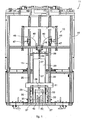
fig. 1 is a front and schematized view of a perforation device according to the present invention, installed on a machine for dispensing coloring products and in the inactive position; -
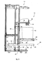
fig. 2 is a lateral and schematized view of the perforation device infig. 1 ; -
fig. 3 is a lateral and schematized view of the perforation device infig. 1 in a first operating position; -
fig. 4 is a lateral and schematized view of the perforation device infig. 1 in a second operating position; -
fig. 5 is a lateral view of a first enlarged detail of the perforation device infig. 1 ; -
fig. 6 is a back and partial view of the perforation device infig. 1 ; -
fig. 7 is a front view of a second enlarged detail of the perforation device infig. 1 ; -
fig. 8 is a lateral view of a third enlarged detail, partly sectioned, of the perforation device infig. 1 . - With reference to
figs. 1 and2 , aperforation device 10 according to the present invention is shown mounted on amachine 11 for preparing and dispensing coloring products, contained in closedcontainers 12, for example metal, one of which is shown, by way of example, infig. 3 . Themachine 11 can be of any known type, for example like the one described in the Italian patent of industrial invention n. 1.279.712, cited above, or any that might be developed in the future. - The
perforation device 10 comprises a frame 15 (figs. 1 and2 ), which is attached to asupport structure 16 of themachine 11. Aperforation member 18 is mounted on theframe 15 at a determinate height from the base. Theperforation member 18 is also of the known type, for example with blades, shaped so as to perforate the upper part or lid of thereceptacle 12, making a hole on it with a diameter suitable to allow the delivery of coloring products inside thereceptacle 12. An example of how theperforation member 18 can be made is described in the Italian patent of industrial invention n. 1.279.712, cited above. - A
plate 20, for example metal, is mounted able to slide vertically with respect to theframe 15 and is mobile between a lower or inactive position, shown infigs. 1 ,2 and3 , and an upper or punching position shown infig. 4 . Asupport plane 21 is mounted cantilevered on theplate 20, on the upper surface of which support plane 21 areceptacle 12 is able to be positioned. - The
support plane 21 is mounted sliding vertically on twouprights 22 of theframe 15, distanced and lateral with respect to theplate 20, and can also be adjusted in height with respect to the latter, depending on the height of thereceptacle 12 to be perforated. In fact, thesupport plane 21 is provided with a clamping peg 25 (fig. 5 ) which is normally held by ahelical spring 26 inside one of the holes of a first plurality ofholes 27 in theplate 20 and aligned vertically (fig. 1 ) substantially at the center thereof. The interaxis between twoadjacent holes 27 is for example about 15 mm. - A knob 28 (
figs. 1 to 5 ) is attached at the end of theclamping peg 25 opposite the end inserted in one of theholes 27 and is drivable manually to temporarily release theclamping peg 25, making it slide axially against the action of thehelical spring 26. Thesupport plane 21 can be raised or lowered manually and thus positioned at the desired height with respect to theplate 20, so that when thereceptacle 12 to be perforated is positioned on thesupport plane 21, the upper part of thereceptacle 12 is at a distance of about 10 mm to about 20 mm from the lower end of theperforation member 18. - The
plate 20 and thesupport plane 21 associated therewith can be raised selectively toward theperforation member 18 by means of alifting mechanism 29, which comprises apedal 30 attached to anexternal end 31 of alever 32 formed by twoarms 33, parallel to each other, thelever 32 being pivoted with aninternal end 34 to apin 35 of theframe 15. - The two
arms 33 of thelever 32 are inserted with play in twovertical slits 37 made in the lower part of theplate 20. - One end of a
cable 36, for example metal, is attached to the twoarms 33 of thelever 32 in an intermediate point between theends plate 20, by means of a fork 38 (fig. 6 ). The opposite end of thecable 36 is attached in the upper part of theplate 20. Thecable 36 passes on afixed pulley 39 rotatably supported by theframe 15. - In the inactive condition, the
lever 32 is substantially horizontal (figs. 1 to 4 ), held in said position at least by the weight of theplate 20 itself, or by a return spring not shown in the drawings, and of thesupport plane 21. Furthermore, in this position, thearms 33 of thelever 32 are disposed in the upper part of theslits 37 of theplate 20. - The
perforation device 10 also comprises asafety mechanism 40, which in turn comprises two hooks 42 (figs. 2 ,3 ,4 and8 ), pivoted in the lower part of theframe 15 and held constantly thrust byhelical springs 43 insidecorresponding holes 45 made in the lower part of theplate 20, between theslits 37. Theholes 45 are disposed on two vertical rows, adjacent and distanced from each other by about 8 mm, and have a vertical interaxis of about 12 mm. - The two
hooks 42 normally hold theplate 20 and the associatedsupport plane 21 clamped in an inactive position; they must be released simultaneously to allow to drive thepedal 30 and to lift thesupport plane 21 toward theperforation member 18. To this purpose thesafety mechanism 40 also comprises twoactuation elements 46, able to be actuated manually and independently, to make the twohooks 42 rotate in an anti-clockwise direction (fig. 8 ) and take them out of thecorresponding holes 45 of theplate 20, against the action of thehelical springs 43. In particular, eachactuation element 46 comprises abutton 47 disposed above theperforation member 18 and on opposite sides with respect to a vertical axis passing through theperforation member 18 and connected to thecorresponding hook 42 by a connectingtie rod 49. - To ensure the
holes 45 correspond to thehooks 42, the lower part of theplate 20 is provided with two vertical eyelets 50 (fig. 7 ) into which two corresponding fixed pegs 51 of theframe 15 are inserted. - The position of the two
actuation elements 46 obliges the operator, for his safety and security, to drive the twobuttons 47 with both hands, before lowering the pedal 30 with his foot and perform the operation to perforate thereceptacle 12. - The
perforation device 10 as described heretofore functions as follows. - First of all the operator has to vertically position the
support plane 21 at the right height - which for example could be indicated by a luminous indicator - with respect to theplate 20, driving theknob 28 manually, depending on the height of thereceptacle 12 to be perforated, so that, at rest, there are from about 10 mm to about 20 mm between the upper surface of thereceptacle 12 and the lower end of theperforation member 18, as described above. - After having positioned the
receptacle 12 on thesupport plane 21, the operator drives the twobuttons 47 with both hands and presses with the foot thepedal 30, thus making thelever 32 rotate in a clockwise direction (fig. 4 ) by an angle α of about 18°-20°. Consequently thecable 36 pulls theplate 20, thesupport plane 21 and thereceptacle 12 upward, making them perform a travel C of about 60-80 mm, and theperforation member 18 perforates thereceptacle 12 properly. - When the
pedal 30 is released, theperforation device 10 automatically returns to the inactive position. - It should be noted that the two
buttons 47 of thesafety mechanism 40 must both be kept actuated until the perforation operation is completed, because if only one of the two were to be released, the correspondinghelical spring 43 would return the associatedhook 42 inside ahole 45, thus clamping theplate 20. - It is clear that modifications and/or additions of parts may be made to the
perforation device 10 as described heretofore, without departing from the field and scope of the present invention. - It is also clear that, although the present invention has been described with reference to some specific examples, a person of skill in the art shall certainly be able to achieve many other equivalent forms of perforation device for perforating closed receptacles containing coloring products, having the characteristics as set forth in the claims and hence all coming within the field of protection defined thereby.
Claims (10)
- Perforation device to perforate closed receptacles (12) containing coloring products, comprising a support plane (21), movable in a substantially vertical direction and on which a receptacle (12) to be perforated is suitable to be disposed, a perforation member (18) positioned at a determinate height, higher than said support plane (21), and actuation means to selectively move said support plane (21) toward said perforation member (18) to cause the perforation of said receptacle (12) to be perforated, wherein said actuation means comprise a lifting mechanism (29) connected to said support plane (21) and drivable by means of a pedal (30), characterized in that it also comprises a safety mechanism (40), suitable to be manually driven, in order to prevent said pedal (30) from being driven by an operator without the latter also driving said safety mechanism (40) at the same time and with both hands.
- Device as in claim 1, characterized in that said lifting mechanism (29) comprises a cable (36) having a first end connected to said pedal (30) and a second end connected to said support plane (21), so that the actuation of said pedal (30) causes the lifting of said support plane (21) toward said perforation member (18).
- Device as in claim 2, characterized in that said support plane (21) is mounted on a plate (20) sliding vertically with respect to a frame (15), and in that said second end of said cable (36) is fixed to said plate (20).
- Device as in claim 3, characterized in that, in an intermediate zone between its two ends, said cable (36) is disposed on a pulley (39) mounted in a fixed position on said frame (15).
- Device as in claim 3 or 4, characterized in that said frame (15) comprises two uprights (22) disposed laterally and on opposite sides with respect to said plate (20) and on which said support plane (21) is able to slide vertically.
- Device as in claim 3, 4 or 5, characterized in that said support plane (21) can be positioned at different heights with respect to said plate (20), using vertical positioning means (25, 28), in order to be selectively positioned, at rest, at a determinate distance from said perforation member (18), depending on the height of said receptacle (12) to be perforated.
- Device as in claim 6, characterized in that said vertical positioning means comprise a first plurality of holes (27) made on said plate (20) and disposed aligned vertically, with which a clamping peg (25) mounted on said support plane (21) is suitable to selectively engage, and which can be selectively dis-engaged by means of a manually driven knob (28).
- Device as in claims 1 and 3, characterized in that said safety mechanism (40) comprises two hooks (42) normally held attached to said plate (20) by elastic means (43) to hold said plate (20) normally clamped in a lowered position, and in that each of said hooks (42) is mechanically connected to an actuation element (46) which can be actuated manually.
- Device as in claim 8, characterized in that each actuation element (46) comprises a button (47) disposed above said perforation member (18) and on opposite sides with respect to a vertical axis passing through said perforation member (18) and connected to the corresponding hook (42) by a connecting tie rod (49).
- Device as in claim 8 or 9, characterized in that said elastic means (43) are suitable to hold said hooks (42) inserted in corresponding second pluralities of holes (45) made in the lower part of said plate (20).
Applications Claiming Priority (2)
| Application Number | Priority Date | Filing Date | Title |
|---|---|---|---|
| IT000032A ITUD20120032A1 (en) | 2012-02-28 | 2012-02-28 | DRILLING DEVICE TO PERFORATE CLOSED CONTAINERS CONTAINING COLORING PRODUCTS |
| PCT/IB2013/000337 WO2013128269A1 (en) | 2012-02-28 | 2013-02-27 | Perforation device to perforate closed receptacles containing coloring products |
Publications (2)
| Publication Number | Publication Date |
|---|---|
| EP2819945A1 EP2819945A1 (en) | 2015-01-07 |
| EP2819945B1 true EP2819945B1 (en) | 2016-09-07 |
Family
ID=46001572
Family Applications (1)
| Application Number | Title | Priority Date | Filing Date |
|---|---|---|---|
| EP13720007.7A Not-in-force EP2819945B1 (en) | 2012-02-28 | 2013-02-27 | Perforation device to perforate closed receptacles containing coloring products |
Country Status (5)
| Country | Link |
|---|---|
| US (1) | US9738503B2 (en) |
| EP (1) | EP2819945B1 (en) |
| IN (1) | IN2014DN07434A (en) |
| IT (1) | ITUD20120032A1 (en) |
| WO (1) | WO2013128269A1 (en) |
Family Cites Families (15)
| Publication number | Priority date | Publication date | Assignee | Title |
|---|---|---|---|---|
| US2733799A (en) * | 1956-02-07 | williams | ||
| US1085529A (en) * | 1913-09-23 | 1914-01-27 | Herman R Blumberg | Safety attachment for presses. |
| US2207297A (en) * | 1937-08-04 | 1940-07-09 | Chicago Flexible Shaft Co | Safety device for kick presses |
| US2350540A (en) * | 1942-11-02 | 1944-06-06 | Harris Seybold Potter Co | Cutting machine |
| US2520068A (en) * | 1945-04-07 | 1950-08-22 | Louis G Seiler | Can punch and drain |
| US2525865A (en) * | 1946-05-17 | 1950-10-17 | Howard T Chisolm | Safety means for treadle operated machinery |
| US2677881A (en) * | 1949-08-17 | 1954-05-11 | Dohm And Nelke Inc | Can opener |
| US3105433A (en) * | 1960-10-28 | 1963-10-01 | Canada Packers Ltd | Vacuum meat pressing apparatus |
| FR1589435A (en) * | 1968-05-03 | 1970-03-31 | ||
| US3821850A (en) * | 1972-12-20 | 1974-07-02 | Blum Inc | Can opener |
| FI58264C (en) * | 1979-05-10 | 1981-01-12 | Winter Oy | MASKIN FOER NYANSERING AV MAOLFAERGER |
| US4570777A (en) * | 1983-10-05 | 1986-02-18 | Hugh J. Baker And Company | Treadle control |
| DE9115379U1 (en) * | 1991-11-19 | 1992-03-26 | Mayer, Georg, 8261 Tittmoning | Device for mechanically splitting wood, especially firewood |
| IT1279712B1 (en) | 1995-12-14 | 1997-12-16 | Corob Srl | PERFORATING AND CAPPING DEVICE FOR A DYE DISPENSING MACHINE OR FLUID PRODUCTS IN GENERAL |
| US6240559B1 (en) * | 1999-10-19 | 2001-06-05 | P & L Company | Garment collar former |
-
2012
- 2012-02-28 IT IT000032A patent/ITUD20120032A1/en unknown
-
2013
- 2013-02-27 EP EP13720007.7A patent/EP2819945B1/en not_active Not-in-force
- 2013-02-27 WO PCT/IB2013/000337 patent/WO2013128269A1/en not_active Ceased
- 2013-02-27 US US14/381,962 patent/US9738503B2/en not_active Expired - Fee Related
-
2014
- 2014-09-04 IN IN7434DEN2014 patent/IN2014DN07434A/en unknown
Also Published As
| Publication number | Publication date |
|---|---|
| US9738503B2 (en) | 2017-08-22 |
| ITUD20120032A1 (en) | 2013-08-29 |
| US20150026989A1 (en) | 2015-01-29 |
| IN2014DN07434A (en) | 2015-04-24 |
| EP2819945A1 (en) | 2015-01-07 |
| WO2013128269A1 (en) | 2013-09-06 |
Similar Documents
| Publication | Publication Date | Title |
|---|---|---|
| US20100258775A1 (en) | Automatic Rising Jack Stand | |
| CN204149590U (en) | Paper bag collating unit | |
| ITBO950591A1 (en) | PERFORATING AND CAPPING DEVICE FOR A DYE DISPENSING MACHINE OR FLUID PRODUCTS IN GENERAL | |
| US9738503B2 (en) | Perforation device to perforate closed receptacles containing coloring products | |
| EP1439000B1 (en) | Apparatus for dosing colored pigments in a container for paint or neutral enamel | |
| CN204990525U (en) | Pushing Mechanism for Prize Game Machines | |
| US20060248857A1 (en) | Improved capsule filling machine | |
| KR100619131B1 (en) | Automatic perforator | |
| US20070223304A1 (en) | Structural improvement handy mixer | |
| ITBO20070589A1 (en) | EQUIPMENT FOR DETERMINING COLORED PIGMENTS IN A PAINTING ENAMEL OR NEUTRAL ENAMEL AND FOR MIXING THE MIXTURE OBTAINED | |
| KR101521228B1 (en) | A vending machine | |
| KR101134009B1 (en) | Up-down apparatus for tray | |
| KR101475008B1 (en) | Rice powder boiling machine | |
| CN211159998U (en) | Make things convenient for jacking device of eminence stone mill maintenance | |
| CN217073731U (en) | Opening and closing mechanism of thermal transfer printer | |
| CN121443187A (en) | Beverage dispenser | |
| US20130296142A1 (en) | Weight Changing Systems And Methods, and Fitness Equipment Incorporating Same | |
| CN214568845U (en) | Feeding device and production line | |
| US6497034B2 (en) | Eyelet and press machine and method for attachment of eyelets and method | |
| CN109576912B (en) | Knee-operated lifting mechanism of sewing machine presser foot | |
| CN219823173U (en) | Logistics supply chain logistics list classification site selection device | |
| CN218011006U (en) | High rotatory tower of security | |
| DE905797C (en) | Punch machine with device for control by sample cards | |
| DE582041C (en) | Switching device for crate ironers to open the protective grille | |
| US1681882A (en) | Pocket-space stamping machine |
Legal Events
| Date | Code | Title | Description |
|---|---|---|---|
| PUAI | Public reference made under article 153(3) epc to a published international application that has entered the european phase |
Free format text: ORIGINAL CODE: 0009012 |
|
| 17P | Request for examination filed |
Effective date: 20140826 |
|
| AK | Designated contracting states |
Kind code of ref document: A1 Designated state(s): AL AT BE BG CH CY CZ DE DK EE ES FI FR GB GR HR HU IE IS IT LI LT LU LV MC MK MT NL NO PL PT RO RS SE SI SK SM TR |
|
| AX | Request for extension of the european patent |
Extension state: BA ME |
|
| DAX | Request for extension of the european patent (deleted) | ||
| GRAP | Despatch of communication of intention to grant a patent |
Free format text: ORIGINAL CODE: EPIDOSNIGR1 |
|
| RAP1 | Party data changed (applicant data changed or rights of an application transferred) |
Owner name: CPS COLOR EQUIPMENT S.P.A. CON UNICO SOCIO |
|
| RAP1 | Party data changed (applicant data changed or rights of an application transferred) |
Owner name: COROB S.P.A. CON UNICO SOCIO |
|
| INTG | Intention to grant announced |
Effective date: 20151209 |
|
| GRAS | Grant fee paid |
Free format text: ORIGINAL CODE: EPIDOSNIGR3 |
|
| GRAA | (expected) grant |
Free format text: ORIGINAL CODE: 0009210 |
|
| AK | Designated contracting states |
Kind code of ref document: B1 Designated state(s): AL AT BE BG CH CY CZ DE DK EE ES FI FR GB GR HR HU IE IS IT LI LT LU LV MC MK MT NL NO PL PT RO RS SE SI SK SM TR |
|
| REG | Reference to a national code |
Ref country code: GB Ref legal event code: FG4D |
|
| REG | Reference to a national code |
Ref country code: CH Ref legal event code: EP |
|
| REG | Reference to a national code |
Ref country code: IE Ref legal event code: FG4D |
|
| REG | Reference to a national code |
Ref country code: AT Ref legal event code: REF Ref document number: 826655 Country of ref document: AT Kind code of ref document: T Effective date: 20161015 |
|
| REG | Reference to a national code |
Ref country code: DE Ref legal event code: R096 Ref document number: 602013011101 Country of ref document: DE |
|
| REG | Reference to a national code |
Ref country code: NL Ref legal event code: FP |
|
| REG | Reference to a national code |
Ref country code: DE Ref legal event code: R082 Ref document number: 602013011101 Country of ref document: DE Representative=s name: VIERING, JENTSCHURA & PARTNER MBB PATENT- UND , DE |
|
| REG | Reference to a national code |
Ref country code: LT Ref legal event code: MG4D |
|
| PG25 | Lapsed in a contracting state [announced via postgrant information from national office to epo] |
Ref country code: LT Free format text: LAPSE BECAUSE OF FAILURE TO SUBMIT A TRANSLATION OF THE DESCRIPTION OR TO PAY THE FEE WITHIN THE PRESCRIBED TIME-LIMIT Effective date: 20160907 Ref country code: FI Free format text: LAPSE BECAUSE OF FAILURE TO SUBMIT A TRANSLATION OF THE DESCRIPTION OR TO PAY THE FEE WITHIN THE PRESCRIBED TIME-LIMIT Effective date: 20160907 Ref country code: HR Free format text: LAPSE BECAUSE OF FAILURE TO SUBMIT A TRANSLATION OF THE DESCRIPTION OR TO PAY THE FEE WITHIN THE PRESCRIBED TIME-LIMIT Effective date: 20160907 Ref country code: NO Free format text: LAPSE BECAUSE OF FAILURE TO SUBMIT A TRANSLATION OF THE DESCRIPTION OR TO PAY THE FEE WITHIN THE PRESCRIBED TIME-LIMIT Effective date: 20161207 Ref country code: RS Free format text: LAPSE BECAUSE OF FAILURE TO SUBMIT A TRANSLATION OF THE DESCRIPTION OR TO PAY THE FEE WITHIN THE PRESCRIBED TIME-LIMIT Effective date: 20160907 |
|
| REG | Reference to a national code |
Ref country code: AT Ref legal event code: MK05 Ref document number: 826655 Country of ref document: AT Kind code of ref document: T Effective date: 20160907 |
|
| REG | Reference to a national code |
Ref country code: FR Ref legal event code: PLFP Year of fee payment: 5 |
|
| PG25 | Lapsed in a contracting state [announced via postgrant information from national office to epo] |
Ref country code: LV Free format text: LAPSE BECAUSE OF FAILURE TO SUBMIT A TRANSLATION OF THE DESCRIPTION OR TO PAY THE FEE WITHIN THE PRESCRIBED TIME-LIMIT Effective date: 20160907 Ref country code: SE Free format text: LAPSE BECAUSE OF FAILURE TO SUBMIT A TRANSLATION OF THE DESCRIPTION OR TO PAY THE FEE WITHIN THE PRESCRIBED TIME-LIMIT Effective date: 20160907 Ref country code: GR Free format text: LAPSE BECAUSE OF FAILURE TO SUBMIT A TRANSLATION OF THE DESCRIPTION OR TO PAY THE FEE WITHIN THE PRESCRIBED TIME-LIMIT Effective date: 20161208 Ref country code: ES Free format text: LAPSE BECAUSE OF FAILURE TO SUBMIT A TRANSLATION OF THE DESCRIPTION OR TO PAY THE FEE WITHIN THE PRESCRIBED TIME-LIMIT Effective date: 20160907 |
|
| PG25 | Lapsed in a contracting state [announced via postgrant information from national office to epo] |
Ref country code: EE Free format text: LAPSE BECAUSE OF FAILURE TO SUBMIT A TRANSLATION OF THE DESCRIPTION OR TO PAY THE FEE WITHIN THE PRESCRIBED TIME-LIMIT Effective date: 20160907 Ref country code: RO Free format text: LAPSE BECAUSE OF FAILURE TO SUBMIT A TRANSLATION OF THE DESCRIPTION OR TO PAY THE FEE WITHIN THE PRESCRIBED TIME-LIMIT Effective date: 20160907 |
|
| PG25 | Lapsed in a contracting state [announced via postgrant information from national office to epo] |
Ref country code: CZ Free format text: LAPSE BECAUSE OF FAILURE TO SUBMIT A TRANSLATION OF THE DESCRIPTION OR TO PAY THE FEE WITHIN THE PRESCRIBED TIME-LIMIT Effective date: 20160907 Ref country code: AT Free format text: LAPSE BECAUSE OF FAILURE TO SUBMIT A TRANSLATION OF THE DESCRIPTION OR TO PAY THE FEE WITHIN THE PRESCRIBED TIME-LIMIT Effective date: 20160907 Ref country code: SM Free format text: LAPSE BECAUSE OF FAILURE TO SUBMIT A TRANSLATION OF THE DESCRIPTION OR TO PAY THE FEE WITHIN THE PRESCRIBED TIME-LIMIT Effective date: 20160907 Ref country code: PT Free format text: LAPSE BECAUSE OF FAILURE TO SUBMIT A TRANSLATION OF THE DESCRIPTION OR TO PAY THE FEE WITHIN THE PRESCRIBED TIME-LIMIT Effective date: 20170109 Ref country code: SK Free format text: LAPSE BECAUSE OF FAILURE TO SUBMIT A TRANSLATION OF THE DESCRIPTION OR TO PAY THE FEE WITHIN THE PRESCRIBED TIME-LIMIT Effective date: 20160907 Ref country code: IS Free format text: LAPSE BECAUSE OF FAILURE TO SUBMIT A TRANSLATION OF THE DESCRIPTION OR TO PAY THE FEE WITHIN THE PRESCRIBED TIME-LIMIT Effective date: 20170107 Ref country code: BG Free format text: LAPSE BECAUSE OF FAILURE TO SUBMIT A TRANSLATION OF THE DESCRIPTION OR TO PAY THE FEE WITHIN THE PRESCRIBED TIME-LIMIT Effective date: 20161207 Ref country code: BE Free format text: LAPSE BECAUSE OF FAILURE TO SUBMIT A TRANSLATION OF THE DESCRIPTION OR TO PAY THE FEE WITHIN THE PRESCRIBED TIME-LIMIT Effective date: 20160907 Ref country code: PL Free format text: LAPSE BECAUSE OF FAILURE TO SUBMIT A TRANSLATION OF THE DESCRIPTION OR TO PAY THE FEE WITHIN THE PRESCRIBED TIME-LIMIT Effective date: 20160907 |
|
| REG | Reference to a national code |
Ref country code: DE Ref legal event code: R097 Ref document number: 602013011101 Country of ref document: DE |
|
| PLBE | No opposition filed within time limit |
Free format text: ORIGINAL CODE: 0009261 |
|
| STAA | Information on the status of an ep patent application or granted ep patent |
Free format text: STATUS: NO OPPOSITION FILED WITHIN TIME LIMIT |
|
| PG25 | Lapsed in a contracting state [announced via postgrant information from national office to epo] |
Ref country code: DK Free format text: LAPSE BECAUSE OF FAILURE TO SUBMIT A TRANSLATION OF THE DESCRIPTION OR TO PAY THE FEE WITHIN THE PRESCRIBED TIME-LIMIT Effective date: 20160907 |
|
| 26N | No opposition filed |
Effective date: 20170608 |
|
| PG25 | Lapsed in a contracting state [announced via postgrant information from national office to epo] |
Ref country code: SI Free format text: LAPSE BECAUSE OF FAILURE TO SUBMIT A TRANSLATION OF THE DESCRIPTION OR TO PAY THE FEE WITHIN THE PRESCRIBED TIME-LIMIT Effective date: 20160907 |
|
| PG25 | Lapsed in a contracting state [announced via postgrant information from national office to epo] |
Ref country code: MC Free format text: LAPSE BECAUSE OF FAILURE TO SUBMIT A TRANSLATION OF THE DESCRIPTION OR TO PAY THE FEE WITHIN THE PRESCRIBED TIME-LIMIT Effective date: 20160907 |
|
| REG | Reference to a national code |
Ref country code: CH Ref legal event code: PL |
|
| PG25 | Lapsed in a contracting state [announced via postgrant information from national office to epo] |
Ref country code: CH Free format text: LAPSE BECAUSE OF NON-PAYMENT OF DUE FEES Effective date: 20170228 Ref country code: LI Free format text: LAPSE BECAUSE OF NON-PAYMENT OF DUE FEES Effective date: 20170228 |
|
| PG25 | Lapsed in a contracting state [announced via postgrant information from national office to epo] |
Ref country code: LU Free format text: LAPSE BECAUSE OF NON-PAYMENT OF DUE FEES Effective date: 20170227 |
|
| REG | Reference to a national code |
Ref country code: FR Ref legal event code: PLFP Year of fee payment: 6 |
|
| PG25 | Lapsed in a contracting state [announced via postgrant information from national office to epo] |
Ref country code: MT Free format text: LAPSE BECAUSE OF NON-PAYMENT OF DUE FEES Effective date: 20170227 |
|
| PG25 | Lapsed in a contracting state [announced via postgrant information from national office to epo] |
Ref country code: AL Free format text: LAPSE BECAUSE OF FAILURE TO SUBMIT A TRANSLATION OF THE DESCRIPTION OR TO PAY THE FEE WITHIN THE PRESCRIBED TIME-LIMIT Effective date: 20160907 |
|
| REG | Reference to a national code |
Ref country code: IE Ref legal event code: MM4A |
|
| PG25 | Lapsed in a contracting state [announced via postgrant information from national office to epo] |
Ref country code: IE Free format text: LAPSE BECAUSE OF NON-PAYMENT OF DUE FEES Effective date: 20170227 |
|
| PG25 | Lapsed in a contracting state [announced via postgrant information from national office to epo] |
Ref country code: HU Free format text: LAPSE BECAUSE OF FAILURE TO SUBMIT A TRANSLATION OF THE DESCRIPTION OR TO PAY THE FEE WITHIN THE PRESCRIBED TIME-LIMIT; INVALID AB INITIO Effective date: 20130227 |
|
| PG25 | Lapsed in a contracting state [announced via postgrant information from national office to epo] |
Ref country code: CY Free format text: LAPSE BECAUSE OF FAILURE TO SUBMIT A TRANSLATION OF THE DESCRIPTION OR TO PAY THE FEE WITHIN THE PRESCRIBED TIME-LIMIT Effective date: 20160907 |
|
| PG25 | Lapsed in a contracting state [announced via postgrant information from national office to epo] |
Ref country code: MK Free format text: LAPSE BECAUSE OF FAILURE TO SUBMIT A TRANSLATION OF THE DESCRIPTION OR TO PAY THE FEE WITHIN THE PRESCRIBED TIME-LIMIT Effective date: 20160907 |
|
| PG25 | Lapsed in a contracting state [announced via postgrant information from national office to epo] |
Ref country code: TR Free format text: LAPSE BECAUSE OF FAILURE TO SUBMIT A TRANSLATION OF THE DESCRIPTION OR TO PAY THE FEE WITHIN THE PRESCRIBED TIME-LIMIT Effective date: 20160907 |
|
| PGFP | Annual fee paid to national office [announced via postgrant information from national office to epo] |
Ref country code: IT Payment date: 20200213 Year of fee payment: 8 Ref country code: NL Payment date: 20200219 Year of fee payment: 8 Ref country code: DE Payment date: 20200219 Year of fee payment: 8 Ref country code: GB Payment date: 20200219 Year of fee payment: 8 |
|
| PGFP | Annual fee paid to national office [announced via postgrant information from national office to epo] |
Ref country code: FR Payment date: 20200219 Year of fee payment: 8 |
|
| REG | Reference to a national code |
Ref country code: DE Ref legal event code: R119 Ref document number: 602013011101 Country of ref document: DE |
|
| GBPC | Gb: european patent ceased through non-payment of renewal fee |
Effective date: 20210227 |
|
| REG | Reference to a national code |
Ref country code: NL Ref legal event code: MM Effective date: 20210301 |
|
| PG25 | Lapsed in a contracting state [announced via postgrant information from national office to epo] |
Ref country code: NL Free format text: LAPSE BECAUSE OF NON-PAYMENT OF DUE FEES Effective date: 20210301 |
|
| PG25 | Lapsed in a contracting state [announced via postgrant information from national office to epo] |
Ref country code: DE Free format text: LAPSE BECAUSE OF NON-PAYMENT OF DUE FEES Effective date: 20210901 Ref country code: GB Free format text: LAPSE BECAUSE OF NON-PAYMENT OF DUE FEES Effective date: 20210227 Ref country code: FR Free format text: LAPSE BECAUSE OF NON-PAYMENT OF DUE FEES Effective date: 20210228 |
|
| PG25 | Lapsed in a contracting state [announced via postgrant information from national office to epo] |
Ref country code: IT Free format text: LAPSE BECAUSE OF NON-PAYMENT OF DUE FEES Effective date: 20210227 |