EP2819397B1 - Imagerie à plage dynamique élevée - Google Patents
Imagerie à plage dynamique élevée Download PDFInfo
- Publication number
- EP2819397B1 EP2819397B1 EP14173298.2A EP14173298A EP2819397B1 EP 2819397 B1 EP2819397 B1 EP 2819397B1 EP 14173298 A EP14173298 A EP 14173298A EP 2819397 B1 EP2819397 B1 EP 2819397B1
- Authority
- EP
- European Patent Office
- Prior art keywords
- capture
- intervals
- capture intervals
- sequence
- images
- Prior art date
- Legal status (The legal status is an assumption and is not a legal conclusion. Google has not performed a legal analysis and makes no representation as to the accuracy of the status listed.)
- Active
Links
Images
Classifications
-
- H—ELECTRICITY
- H04—ELECTRIC COMMUNICATION TECHNIQUE
- H04N—PICTORIAL COMMUNICATION, e.g. TELEVISION
- H04N25/00—Circuitry of solid-state image sensors [SSIS]; Control thereof
- H04N25/50—Control of the SSIS exposure
- H04N25/57—Control of the dynamic range
- H04N25/58—Control of the dynamic range involving two or more exposures
-
- G—PHYSICS
- G06—COMPUTING OR CALCULATING; COUNTING
- G06T—IMAGE DATA PROCESSING OR GENERATION, IN GENERAL
- G06T5/00—Image enhancement or restoration
- G06T5/50—Image enhancement or restoration using two or more images, e.g. averaging or subtraction
-
- H—ELECTRICITY
- H04—ELECTRIC COMMUNICATION TECHNIQUE
- H04N—PICTORIAL COMMUNICATION, e.g. TELEVISION
- H04N23/00—Cameras or camera modules comprising electronic image sensors; Control thereof
- H04N23/60—Control of cameras or camera modules
- H04N23/698—Control of cameras or camera modules for achieving an enlarged field of view, e.g. panoramic image capture
-
- H—ELECTRICITY
- H04—ELECTRIC COMMUNICATION TECHNIQUE
- H04N—PICTORIAL COMMUNICATION, e.g. TELEVISION
- H04N23/00—Cameras or camera modules comprising electronic image sensors; Control thereof
- H04N23/70—Circuitry for compensating brightness variation in the scene
- H04N23/741—Circuitry for compensating brightness variation in the scene by increasing the dynamic range of the image compared to the dynamic range of the electronic image sensors
-
- H—ELECTRICITY
- H04—ELECTRIC COMMUNICATION TECHNIQUE
- H04N—PICTORIAL COMMUNICATION, e.g. TELEVISION
- H04N23/00—Cameras or camera modules comprising electronic image sensors; Control thereof
- H04N23/95—Computational photography systems, e.g. light-field imaging systems
- H04N23/951—Computational photography systems, e.g. light-field imaging systems by using two or more images to influence resolution, frame rate or aspect ratio
-
- H—ELECTRICITY
- H04—ELECTRIC COMMUNICATION TECHNIQUE
- H04N—PICTORIAL COMMUNICATION, e.g. TELEVISION
- H04N25/00—Circuitry of solid-state image sensors [SSIS]; Control thereof
- H04N25/40—Extracting pixel data from image sensors by controlling scanning circuits, e.g. by modifying the number of pixels sampled or to be sampled
- H04N25/41—Extracting pixel data from a plurality of image sensors simultaneously picking up an image, e.g. for increasing the field of view by combining the outputs of a plurality of sensors
-
- H—ELECTRICITY
- H04—ELECTRIC COMMUNICATION TECHNIQUE
- H04N—PICTORIAL COMMUNICATION, e.g. TELEVISION
- H04N25/00—Circuitry of solid-state image sensors [SSIS]; Control thereof
- H04N25/50—Control of the SSIS exposure
- H04N25/57—Control of the dynamic range
- H04N25/58—Control of the dynamic range involving two or more exposures
- H04N25/587—Control of the dynamic range involving two or more exposures acquired sequentially, e.g. using the combination of odd and even image fields
-
- H—ELECTRICITY
- H04—ELECTRIC COMMUNICATION TECHNIQUE
- H04N—PICTORIAL COMMUNICATION, e.g. TELEVISION
- H04N13/00—Stereoscopic video systems; Multi-view video systems; Details thereof
- H04N2013/0074—Stereoscopic image analysis
- H04N2013/0088—Synthesising a monoscopic image signal from stereoscopic images, e.g. synthesising a panoramic or high resolution monoscopic image
Definitions
- the present invention relates to high dynamic range imaging, with particular relation to high dynamic range moving images. Most particularly, the present invention relates to an improved method for high dynamic range imaging and a system for implementing the same.
- US 2002/0118293 A1 discloses a method and system for capturing and displaying a series of successive video images using at least first and second different exposure times, so that first video images captured using the first exposure time occur alternatively in series with second video images captured using said second exposure time.
- Composite images may be derived from the first and second video images.
- a third video image captured with a third different exposure time may be introduced into the series.
- a method for high dynamic range imaging comprising the steps of: defining n capture intervals where n is 3 or above; capturing a series of images at the said capture intervals in a repeating sequence of 2n-2 steps, wherein the first n steps of the sequence comprise one of each capture interval, and the n-2 capture intervals between the first and the n th capture intervals are then duplicated for the subsequent steps of the sequence and wherein each of the n-2 capture intervals between the first and the n th capture intervals that is in an odd position in the first n capture intervals of the sequence maintains an odd position when duplicated in the subsequent steps of the sequence and each of the n-2 capture intervals between the first and the n th capture intervals that is in an even position in the first n capture intervals within the sequence maintains an even position when duplicated in the subsequent steps of the sequence; and combining n successive captured images to generate a series of composite frames for output.
- the present invention thereby provides a sequence for high dynamic range imaging using more than two different capture intervals.
- n-2 of the capture intervals in the sequence By duplicating n-2 of the capture intervals in the sequence in this manner, a sequence is provided whereby for a steady scene captured by an imaging array operating in an interlaced manner, only one set of detector rows operates on each occurrence of a particular capture interval. Whichever set of rows operates on a capture interval in the first n steps of the sequence, will also operate on all subsequent uses of that interval in the sequence. This eliminates interlace bounce in the resultant image.
- the n capture intervals are n different capture intervals.
- the scaling relationship between pixel values obtained from the different capture intervals may be determined by a predetermined analysis method.
- the determination may involve the steps of: identifying groups of corresponding pixel positions within images of the same scene at different capture intervals, wherein the pixel values are neither too bright nor too dark; and applying a predetermined analysis method to said pixel values so as to identify a common scale factor and offset.
- the predetermined method may be a computational method.
- the predetermined method used to identify the scaling relationship is linear regression.
- the predetermined method may be taking the mean of the ratios of corresponding pixel values obtained from different capture intervals.
- the predetermined method may be a Robust Estimation method.
- An example of a suitable Robust Estimation method is set out in section 15.7 of 'Numerical Recipes in C: The Art of Scientific Computing' by William H. Press et al.
- the capture intervals may be any suitable interval. Typically, the capture intervals may be of the order of 0.1 - 20 milliseconds.
- the range of capture intervals may be dependent on the desired image: where a dark biased composite image is required, the set of n capture intervals may include more than one relatively long capture interval and these long intervals may be duplicated in the sequence. Where a light biased image is required, the set of n capture intervals may include more than one relatively short capture intervals and these short intervals may be duplicated in the sequence.
- the skilled man will of course appreciate that different sets of capture intervals and/or different scaling relationships between capture intervals may be appropriate in different circumstances.
- each group of successive captured images comprises one image captured at each of the n capture intervals.
- overlapping groups of n successive captured images are combined to generate composite frames.
- One or more of the n successive captured images used to generate a composite frame may overlap with one or more of the n successive captured images used to generate the subsequent composite frame.
- the overlap may comprise one captured image.
- the effective frame rate can be increased as compared with composite images comprising non-overlapping successive groups of captured images whilst still eliminating interlace bounce.
- an imaging system comprising: an imaging array operable to capture images at n different capture intervals where n is 3 or above and operate in a repeating sequence of 2n-2 steps whereby the different capture intervals are each used for one of the first n steps of the sequence, and the n - 2 intervals between the first and the n th intervals are then duplicated for the subsequent steps of the sequence and wherein each of the n-2 capture intervals between the first and the n th capture intervals that is in an odd position in the first n capture intervals of the sequence maintains an odd position when duplicated in the subsequent steps of the sequence and each of the n-2 capture intervals between the first and the n th capture intervals that is in an even position in the first n capture intervals within the sequence maintains an even position when duplicated in the subsequent steps of the sequence and an imagining processing means to combine successive captured images to generate a series of composite frames for output.
- the system of the second aspect of the present invention may incorporate any or all features of the method of the first aspect of the present invention as desired or appropriate.
- the imaging array may be operable to capture incident radiation at any suitable frequency range.
- the array may be operable to capture infrared and/or visible light.
- the imaging array may operate in an interleaved manner wherein alternate rows of detector elements are operable to capture successive images.
- the imaging system may incorporate an image processing means.
- the image processing means may be operable to determine a scaling relationship between pixel values obtained from the different capture intervals.
- image processing means may be operable to: identify groups of corresponding pixel positions within images of the same scene at different capture intervals, wherein the pixel values are neither too bright nor too dark; and apply a predetermined analysis method to said pixel values so as to identify a common scale factor and offset.
- imaging performance can vary with operating temperature, overall scene brightness or other factors, dynamically determining a scaling relationship in this manner may provide a better image than continuing to use a preset scaling relationship.
- the image processing means may be operable to apply linear regression to said pixel values so as to identify a common scale factor and offset.
- the image processing means may be operable to take the mean of the ratios of corresponding pixel values obtained from different capture intervals so as to identify a common scale factor and offset.
- the image processing means may be operable to apply a method of Robust Estimation.
- a suitable Robust Estimation method is set out in section 15.7 of 'Numerical Recipes in C: The Art of Scientific Computing' by William H. Press et al to said pixel values so as to identify a common scale factor and offset.
- the image processing means may be operable to determine the scale factor and offset for each group of subsequent frames used in a composite image.
- the image processing means may be operable to determine the scale factor and offset continuously.
- the capture intervals are of the order of 0.1 - 20 milliseconds.
- the processing means is operable to act on overlapping groups of n successive captured images to generate composite frames, wherein each of the n successive captured images is captured at a different capture interval.
- One or more of the n successive captured images used to generate a composite frame may overlap with one or more of the n successive captured images used to generate the subsequent composite frame.
- the image processing means may be operable to overlap the groups of successive images combined to generate a composite frame by one captured image.
- the imaging system may additionally incorporate display means operable to display the captured images or the composite frames.
- the display means may be operable to display the captured images or the composite frames in the same sequence as they were captured.
- the display means may operate in an interleaved manner wherein alternate rows of pixels are used for successive images or frames.
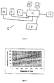
- the imaging system 10 of the present invention comprises an imaging array 11, processing means 12 and a display 13.
- the imaging array 11 is operable to capture a succession of images by detecting incident light.
- the processing means 12 is operable to process said images as required, and pass the processed images to the display 13 for output.
- the imaging array 11 may be provided with a suitable lens arrangement 14 for focusing incident light and/or a shutter 15 for controlling the incidence of light.
- the lens arrangement 14 and shutter 15 maybe controlled by the processing means 12.
- the processing means may be further connected to user operable input controls 16, a storage unit 17 for storing captured images and communication means 18 for enabling data to be transmitted to or received from external devices via a suitable wired or wireless link.
- the number of capture intervals, n is 3: a long capture interval, a medium capture interval and a short capture interval.
- the imaging array 11 captures a series of images using the three different capture intervals. By combining these captured images, output images with a wide dynamic range can be produced.
- the long capture interval is 8ms
- the medium capture interval is 1ms
- the short capture interval is 0.1ms.
- different capture intervals and/or different scaling between the capture intervals may be used where appropriate.
- the number of capture intervals, n is 5.
- the imaging array 11 captures a series of images using five different capture intervals. By combining these captured images, output images with a wide dynamic range can be produced.
- An example of five possible capture intervals would be 20ms, 8ms, 2ms, 0.5ms and 0.1ms.
- different capture intervals and/or different scaling between the capture intervals may be used in either of the above embodiments where appropriate.
- the mutual scaling between pixel values from different capture intervals may be predetermined based on preset scaling determined at manufacture or during calibration.
- the processing means 12 may be operable to determine a scaling relationship between pixel values from the different capture intervals.
- a pixel value is obtained by sampling the output signal from the corresponding element in the array using an analogue to digital converter (ADC).
- ADC analogue to digital converter
- black pixels do not have a digitised value of 0.
- the range "black to white" is more like "100 to 1000".
- the pixels in each image will have a linear relationship, defined by a scale factor.
- the scale factor will be roughly in line with the ratio of exposure times and the offset will be related to the ADC output level for black pixels.
- the pixel values of corresponding pixel positions within images of the same scene at different capture intervals are compared. Pixel positions where the pixel values in one of the images are too bright (saturated), or too dark (black) are identified and eliminated from processing.
- the pixel values for a given position at different capture intervals can then be compared and subjected to a predetermined analysis method to determine the appropriate scale factor and offset.
- the analysis method is linear regression, and a visual example using pair of pixel values from two different capture intervals is shown in figure 2 .
- the imaging array 11 operates in a repeating four step sequence.
- An example four step sequence is: long capture interval; medium capture interval; short capture interval; medium capture interval.
- additional detail can typically be imaged in the midpart of the imaging range. If a dark biased image or a light biased image is preferred, the skilled man will appreciate that the sequence may be adapted to repeat the long capture interval or short capture interval respectively.
- Sequential operation of the type described above allows the array 11 to be operated in an interleaved manner wherein alternate rows of detector elements are operable to capture successive images and the display 13 to similarly operate in an interleaved manner wherein alternate rows of pixels are used for successive frames. If the interleaved captured images are passed directly to the display, for a steady scene, since there is a four step process, the same detector elements in the array 11 map to the same pixels in the display 13 for each capture interval. Accordingly interlace bounce is avoided. This example is further discussed below.
- the imaging array 11 operates in a repeating eight step sequence.
- the n capture intervals (20ms, 8ms, 2ms, 0.5ms and 0.1ms in this example) are defined as A , b , C, d and E , with any capture interval corresponding to any letter
- an example eight step sequence is: A , b , C, d, E , d, C, b .
- the sequence may be adapted to appropriately bias an image toward light or dark respectively.
- Sequential operation of the type described above allows the array 11 to be operated in an interleaved manner wherein alternate rows of detector elements are operable to capture successive images and the display 13 to similarly operate in an interleaved manner wherein alternate rows of pixels are used for successive frames. If the interleaved captured images are passed directly to the display, for a steady scene, the same detector elements in the array 11 map to the same pixels in the display 13 for each capture interval. In this example, the lower case intervals in the sequence would map to the same detector elements in the array 11, and the upper case intervals would map to the other row of detector elements. As each capture interval is only operated at one of the two sets of detector rows, interlace bounce is avoided.
- a second eight step sequence is possible that also avoids interlace bounce: A, b, C, d, E, b, C, d.
- b and d occur in even positions in the first 5 steps of the sequence and, though they have been 'swapped', have maintained even positions in the subsequent steps of the sequence.
- all instances of capture intervals b and d would still be operated on in the same detector row and as such interlace bounce is still avoided.
- any other permutation of the five capture intervals within the eight step sequence would either introduce interlace bounce by or create a sequence such that the composite frames of n subsequent captured images would not contain one image captured at each of the n intervals, this would reduce the dynamic range of the composite frame.
- the processing means 12 may be operable to combine successive groups of captured images to generate a composite frame for output by the display unit 13.
- this can be implemented using overlapping groups of three captured images such that the three successive captured images are images captured at each of the short, medium and long capture intervals. This has the benefit of providing an increased effective frame rate compared to the conventional method whereby non-overlapping groups of successive images are combined to create successive composite frames.
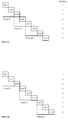
- ... 8ms, 1ms, 0.1ms, 1ms ... composite frames may be generated by using groups of images that overlap by one image ... (8ms, 1ms, 0.1ms), (0.1ms, 1ms, 8ms), (8ms, 1ms, 0.1ms) ... as set out in figure 3a .
- the effective frame rate for the composite frames is around 25 frames per second.
- successive composite frames would be generated by combining the outputs of non-overlapping groups of captured images ... (8ms, 1ms, 0.1ms), (8ms, 1ms, 0.1ms), (8ms, 1ms, 0.1ms), ... as set out in figure 3b .
- the mid-range pixels are unique in each frame and on alternate frames the high or low pixel is repeated, providing increased temporal resolution at the mid part of the scale but reducing temporal resolution at the extremities of the range.
- different parts of the scale can be prioritised by choosing different repeated capture intervals as indicated above.
- the repeated medium interval is always taken from row set 2.
- the medium interval is taken from alternating sets in successive frames thus causing bounce.
- the processing means 12 may be operable to combine successive groups of five captured images to generate a composite frame for output by the display unit 13.
- the five successive images are each captured at a different capture interval and the groups of five successive images used for consecutive composite frames overlap by one captured image.
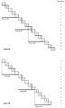
- ... 20ms (A), 8ms (b), 2ms (C), 0.5ms (d), 0.1ms (E), 0.5ms (d), 2ms (C), 8ms (b) ... composite frames may be generated by using groups of images that overlap by one image.
- the first three composite frames would be: (20ms, 8ms, 2ms, 0.5ms, 0.1ms), (0.1ms, 0.5ms, 2ms, 8ms, 20ms), (20ms, 8ms, 2ms, 0.5ms, 0.1ms). This is set out in Figure 4a .
- Overlapping groups of this kind would result in an effective composite frame rate of around 12.5 frames per second when using standard 50Hz capture electronics.
- the prior art arrangement using a simple five step consecutive repeating sequence is set out in figure 4b .
- successive composite frames would be generated by combining the outputs of non-overlapping groups of captured images ... (A, b, C, d, E), (A, b, C, d, E), (A, b, C, d, E) ... as shown.
- the prior art technique would give an effective composite frame rate of around 10 frames per second using standard 50 Hz capture electronics. Accordingly, the technique of the present invention can once again be seen to provide an increased effective frame rate.
- repeated intervals b , C , and d are always taken from row sets 2, 1 and 2 respectively, and intervals A and E are always taken from row set 1. Interlace bounce is therefore avoided.
- FIG 4b there are no repeated capture intervals, causing an interlace bounce. This can be seen, for example, by looking at capture interval A : the first instance of capture interval A is taken from row set 1, and the second instance of capture interval A is taken from row set 2, causing an interlace bounce.
Landscapes
- Engineering & Computer Science (AREA)
- Multimedia (AREA)
- Signal Processing (AREA)
- Theoretical Computer Science (AREA)
- Computing Systems (AREA)
- Physics & Mathematics (AREA)
- General Physics & Mathematics (AREA)
- Studio Devices (AREA)
- Transforming Light Signals Into Electric Signals (AREA)
Claims (15)
- Procédé d'imagerie à plage dynamique élevée comprenant les étapes consistant à : définir n intervalles de capture, où n est égal ou supérieur à 3 ; capturer une série d'images auxdits intervalles de capture dans une séquence répétitive de 2n-2 étapes, dans lequel les premières n étapes de la séquence comprennent un de chaque intervalle de capture, et les n-2 intervalles de capture entre les premier et nième intervalles de capture sont ensuite dupliqués pour les étapes subséquentes de la séquence, et dans lequel chacun des n-2 intervalles de capture entre les premier et nième intervalles de capture qui se situe dans une position impaire dans les premiers n intervalles de capture de la séquence maintient une position impaire lorsqu'il est dupliqué dans les étapes subséquentes de la séquence, et chacun des n-2 intervalles de capture entre les premier et nième intervalles de capture qui se situe dans une position paire dans les premiers n intervalles de capture au sein de la séquence maintient une position paire lorsqu'il est dupliqué dans les étapes subséquentes de la séquence ; et combiner n images capturées successives en vue de générer une série de trames composites à générer en sortie.
- Procédé d'imagerie à plage dynamique élevée selon la revendication 1, dans lequel une relation de mise à l'échelle entre des valeurs de pixels provenant de différents intervalles de capture est déterminée par : l'identification de groupes de positions de pixels correspondantes au sein d'images de la même scène à différents intervalles de capture, dans lequel les valeurs de pixels ne sont ni trop claires, ni trop foncées ; et l'application de l'un ou l'une quelconque parmi : un procédé de calcul informatique ; une régression linéaire ; le calcul de la moyenne des taux des valeurs de pixels correspondantes obtenues à partir de différents intervalles de capture ; ou un procédé d'estimation robuste sur lesdites valeurs de pixels de manière à identifier un décalage et un facteur d'échelle communs.
- Procédé d'imagerie à plage dynamique élevée selon la revendication 1 ou 2, dans lequel les intervalles de capture sont de l'ordre de 0,1 à 20 millisecondes.
- Procédé d'imagerie à plage dynamique élevée selon l'une quelconque des revendications précédentes, dans lequel chaque groupe d'images capturées successives comprend une image capturée à chacun des n intervalles de capture.
- Procédé d'imagerie à plage dynamique élevée selon l'une quelconque des revendications précédentes, dans lequel une ou plusieurs des n images capturées successives utilisées en vue de générer une trame composite sont en chevauchement avec une ou plusieurs des n images capturées successives utilisées en vue de générer la trame composite subséquente.
- Procédé d'imagerie à plage dynamique élevée selon la revendication 5, dans lequel le chevauchement comprend une image capturée.
- Système d'imagerie (10) comprenant : une matrice d'imagerie (11) exploitable de manière à capturer des images à n différents intervalles de capture, où n est égal ou supérieur à 3, et à fonctionner dans une séquence répétitive de 2n-2 étapes moyennant quoi les différents intervalles de capture sont chacun utilisés pour l'une des premières n étapes de la séquence, et les n-2 intervalles entre les premier et nième intervalles sont ensuite dupliqués pour les étapes subséquentes de la séquence, et dans lequel chacun des n-2 intervalles de capture entre les premier et nième intervalles de capture qui se situe dans une position impaire dans les premiers n intervalles de capture de la séquence maintient une position impaire lorsqu'il est dupliqué dans les étapes subséquentes de la séquence, et chacun des n-2 intervalles de capture entre les premier et nième intervalles de capture qui se situe dans une position paire dans les premiers n intervalles de capture au sein de la séquence maintient une position paire lorsqu'il est dupliqué dans les étapes subséquentes de la séquence, et un moyen de traitement d'images (12) pour combiner des images capturées successives en vue de générer une série de trames composites à générer en sortie.
- Système d'imagerie (10) selon la revendication 7, dans lequel la matrice d'imagerie (11) fonctionne d'une manière entrelacée, dans lequel des rangées alternées d'éléments détecteurs sont exploitables de manière à capturer des images successives.
- Système d'imagerie (10) selon la revendication 7 ou 8, dans lequel le moyen de traitement d'images (12) est exploitable de manière à déterminer une relation de mise à l'échelle entre des valeurs de pixels obtenues à partir des différents intervalles de capture, par : l'identification de groupes de positions de pixels correspondantes au sein d'images de la même scène à différents intervalles de capture, dans lequel les valeurs de pixels ne sont ni trop claires, ni trop foncées ; et l'application de l'un ou l'une quelconque parmi : une régression linéaire ; le calcul de la moyenne des taux des valeurs de pixels correspondantes obtenues à partir de différents intervalles de capture ; ou une estimation robuste sur lesdites valeurs de pixels de manière à identifier un décalage et un facteur d'échelle communs.
- Système d'imagerie (10) selon la revendication 9, dans lequel le moyen de traitement d'images (12) est exploitable de manière à déterminer le décalage et le facteur d'échelle pour chaque groupe de trames subséquentes utilisées dans une image composite.
- Système d'imagerie (10) selon la revendication 9 ou 10, dans lequel le moyen de traitement d'images (12) est exploitable de manière à déterminer le décalage et le facteur d'échelle en continu.
- Système d'imagerie (10) selon l'une quelconque des revendications 7 à 11, dans lequel le moyen de traitement d'images (12) est exploitable de manière à agir sur des groupes en chevauchement de n images capturées successives en vue de générer des trames composites, dans lequel chacune des n images capturées successives est capturée à un intervalle de capture différent.
- Système d'imagerie (10) selon l'une quelconque des revendications 7 à 12, dans lequel le moyen de traitement d'images (12) est exploitable de manière à faire se chevaucher les groupes d'images successives combinées pour générer une trame composite, par une image capturée.
- Système d'imagerie selon l'une quelconque des revendications 7 à 13, comprenant en outre un moyen d'affichage exploitable de manière à afficher les images capturées ou les trames composites.
- Système d'imagerie selon la revendication 14, dans lequel le moyen d'affichage opère d'une manière entrelacée, dans lequel des rangées alternées de pixels sont utilisées pour des trames ou des images successives.
Applications Claiming Priority (1)
| Application Number | Priority Date | Filing Date | Title |
|---|---|---|---|
| GBGB1311366.7A GB201311366D0 (en) | 2013-06-26 | 2013-06-26 | High dynamic range imaging |
Publications (3)
| Publication Number | Publication Date |
|---|---|
| EP2819397A2 EP2819397A2 (fr) | 2014-12-31 |
| EP2819397A3 EP2819397A3 (fr) | 2015-01-14 |
| EP2819397B1 true EP2819397B1 (fr) | 2016-01-20 |
Family
ID=48998990
Family Applications (1)
| Application Number | Title | Priority Date | Filing Date |
|---|---|---|---|
| EP14173298.2A Active EP2819397B1 (fr) | 2013-06-26 | 2014-06-20 | Imagerie à plage dynamique élevée |
Country Status (3)
| Country | Link |
|---|---|
| US (1) | US9344648B2 (fr) |
| EP (1) | EP2819397B1 (fr) |
| GB (2) | GB201311366D0 (fr) |
Cited By (1)
| Publication number | Priority date | Publication date | Assignee | Title |
|---|---|---|---|---|
| US10873714B2 (en) | 2017-11-09 | 2020-12-22 | Semiconductor Components Industries, Llc | Image sensor with multiple pixel access settings |
Families Citing this family (1)
| Publication number | Priority date | Publication date | Assignee | Title |
|---|---|---|---|---|
| CN107782738A (zh) * | 2016-08-31 | 2018-03-09 | 上海微电子装备(集团)股份有限公司 | 一种自动光学检测装置及其检测方法 |
Family Cites Families (10)
| Publication number | Priority date | Publication date | Assignee | Title |
|---|---|---|---|---|
| US7193652B2 (en) * | 1999-08-17 | 2007-03-20 | Applied Vision Systems, Inc. | Dynamic range video recording and playback system and method |
| US7382407B2 (en) * | 2002-08-29 | 2008-06-03 | Micron Technology, Inc. | High intrascene dynamic range NTSC and PAL imager |
| US7239805B2 (en) * | 2005-02-01 | 2007-07-03 | Microsoft Corporation | Method and system for combining multiple exposure images having scene and camera motion |
| US8059174B2 (en) * | 2006-05-31 | 2011-11-15 | Ess Technology, Inc. | CMOS imager system with interleaved readout for providing an image with increased dynamic range |
| CN101867727B (zh) * | 2009-04-16 | 2011-12-07 | 华为技术有限公司 | 一种视频处理方法及装置 |
| US8405750B2 (en) * | 2009-06-08 | 2013-03-26 | Aptina Imaging Corporation | Image sensors and image reconstruction methods for capturing high dynamic range images |
| JP2013509820A (ja) * | 2009-10-28 | 2013-03-14 | ザ トラスティーズ オブ コロンビア ユニヴァーシティ イン ザ シティ オブ ニューヨーク | 符号化ローリングシャッタの方法およびシステム |
| US20130033622A1 (en) * | 2011-08-04 | 2013-02-07 | Aptina Imaging Corporation | Method and apparatus for motion artifact correction in hdr video |
| US8809759B2 (en) * | 2011-10-11 | 2014-08-19 | Omnivision Technologies, Inc. | Multiple-row concurrent readout scheme for high-speed CMOS image sensor with backside illumination |
| US9007488B2 (en) * | 2012-03-08 | 2015-04-14 | Semiconductor Components Industries, Llc | Systems and methods for generating interpolated high-dynamic-range images |
-
2013
- 2013-06-26 GB GBGB1311366.7A patent/GB201311366D0/en not_active Ceased
-
2014
- 2014-06-20 GB GB1411031.6A patent/GB2517563A/en not_active Withdrawn
- 2014-06-20 EP EP14173298.2A patent/EP2819397B1/fr active Active
- 2014-06-23 US US14/312,140 patent/US9344648B2/en active Active
Cited By (1)
| Publication number | Priority date | Publication date | Assignee | Title |
|---|---|---|---|---|
| US10873714B2 (en) | 2017-11-09 | 2020-12-22 | Semiconductor Components Industries, Llc | Image sensor with multiple pixel access settings |
Also Published As
| Publication number | Publication date |
|---|---|
| EP2819397A2 (fr) | 2014-12-31 |
| GB201311366D0 (en) | 2013-08-14 |
| GB201411031D0 (en) | 2014-08-06 |
| US20150002714A1 (en) | 2015-01-01 |
| GB2517563A (en) | 2015-02-25 |
| US9344648B2 (en) | 2016-05-17 |
| EP2819397A3 (fr) | 2015-01-14 |
Similar Documents
| Publication | Publication Date | Title |
|---|---|---|
| US10694122B2 (en) | Methods and apparatus for true high dynamic range imaging | |
| US9699429B2 (en) | Image processing apparatus, imaging device, image processing method, and program for reducing noise or false colors in an image | |
| US10594948B2 (en) | Imaging device that generates multiple-exposure image data | |
| US8274573B2 (en) | Method and system for generating high temporal resolution video from low temporal resolution videos | |
| US11184554B2 (en) | Apparatus for transmitting a control signal for driving a driving mode | |
| CN102572245B (zh) | 一种扩展图像动态范围的方法及装置 | |
| US20150350567A1 (en) | Data digitization and display for an imaging system | |
| EP2360910A2 (fr) | Appareil de capture d'images | |
| JP2016208307A (ja) | 画像処理装置、その制御方法及びプログラム | |
| CN113810621A (zh) | 一种应用于多线线阵相机的分时曝光和tdi并行处理装置及方法 | |
| US10591711B2 (en) | Microscope and method for obtaining a high dynamic range synthesized image of an object | |
| EP3230948A1 (fr) | Procédé et appareil de production d'un flux vidéo | |
| US20240259706A1 (en) | Systems, methods, and media for high dynamic range imaging using single-photon and conventional image sensor data | |
| EP1641249A1 (fr) | Améliorations relatives à des capteurs d'images | |
| EP2819397B1 (fr) | Imagerie à plage dynamique élevée | |
| CN110389463B (zh) | 用于显示高动态范围图像的方法及系统 | |
| JP6863281B2 (ja) | 撮像装置、および情報処理システム | |
| US9019401B2 (en) | System and method for creating an image with a wide dynamic range | |
| EP3162072A1 (fr) | Systèmes et procédés permettant une imagerie compressive | |
| US12225299B2 (en) | System and method for image banding detection | |
| US10091441B1 (en) | Image capture at multiple resolutions | |
| EP4055814B1 (fr) | Système pour effectuer une compensation de mouvement d'image | |
| JP2020028115A5 (ja) | 撮像装置および画像処理装置 | |
| WO2016003521A1 (fr) | Amélioration de contraste vidéo avec des sous-segments | |
| EP0516778B1 (fr) | Appareil et méthode pour la suppression d'impulsions perturbatrices de durée courte dans des signaux vidéo |
Legal Events
| Date | Code | Title | Description |
|---|---|---|---|
| PUAL | Search report despatched |
Free format text: ORIGINAL CODE: 0009013 |
|
| PUAI | Public reference made under article 153(3) epc to a published international application that has entered the european phase |
Free format text: ORIGINAL CODE: 0009012 |
|
| 17P | Request for examination filed |
Effective date: 20140620 |
|
| AK | Designated contracting states |
Kind code of ref document: A2 Designated state(s): AL AT BE BG CH CY CZ DE DK EE ES FI FR GB GR HR HU IE IS IT LI LT LU LV MC MK MT NL NO PL PT RO RS SE SI SK SM TR |
|
| AX | Request for extension of the european patent |
Extension state: BA ME |
|
| AK | Designated contracting states |
Kind code of ref document: A3 Designated state(s): AL AT BE BG CH CY CZ DE DK EE ES FI FR GB GR HR HU IE IS IT LI LT LU LV MC MK MT NL NO PL PT RO RS SE SI SK SM TR |
|
| AX | Request for extension of the european patent |
Extension state: BA ME |
|
| RIC1 | Information provided on ipc code assigned before grant |
Ipc: H04N 5/235 20060101AFI20141211BHEP Ipc: G06T 5/50 20060101ALI20141211BHEP |
|
| R17P | Request for examination filed (corrected) |
Effective date: 20150709 |
|
| RBV | Designated contracting states (corrected) |
Designated state(s): AL AT BE BG CH CY CZ DE DK EE ES FI FR GB GR HR HU IE IS IT LI LT LU LV MC MK MT NL NO PL PT RO RS SE SI SK SM TR |
|
| GRAP | Despatch of communication of intention to grant a patent |
Free format text: ORIGINAL CODE: EPIDOSNIGR1 |
|
| INTG | Intention to grant announced |
Effective date: 20150924 |
|
| GRAS | Grant fee paid |
Free format text: ORIGINAL CODE: EPIDOSNIGR3 |
|
| GRAA | (expected) grant |
Free format text: ORIGINAL CODE: 0009210 |
|
| AK | Designated contracting states |
Kind code of ref document: B1 Designated state(s): AL AT BE BG CH CY CZ DE DK EE ES FI FR GB GR HR HU IE IS IT LI LT LU LV MC MK MT NL NO PL PT RO RS SE SI SK SM TR |
|
| REG | Reference to a national code |
Ref country code: GB Ref legal event code: FG4D |
|
| REG | Reference to a national code |
Ref country code: CH Ref legal event code: EP |
|
| REG | Reference to a national code |
Ref country code: IE Ref legal event code: FG4D |
|
| REG | Reference to a national code |
Ref country code: AT Ref legal event code: REF Ref document number: 772195 Country of ref document: AT Kind code of ref document: T Effective date: 20160215 |
|
| REG | Reference to a national code |
Ref country code: DE Ref legal event code: R096 Ref document number: 602014000785 Country of ref document: DE |
|
| REG | Reference to a national code |
Ref country code: FR Ref legal event code: PLFP Year of fee payment: 3 |
|
| REG | Reference to a national code |
Ref country code: LT Ref legal event code: MG4D Ref country code: NL Ref legal event code: MP Effective date: 20160120 |
|
| REG | Reference to a national code |
Ref country code: AT Ref legal event code: MK05 Ref document number: 772195 Country of ref document: AT Kind code of ref document: T Effective date: 20160120 |
|
| PG25 | Lapsed in a contracting state [announced via postgrant information from national office to epo] |
Ref country code: NL Free format text: LAPSE BECAUSE OF FAILURE TO SUBMIT A TRANSLATION OF THE DESCRIPTION OR TO PAY THE FEE WITHIN THE PRESCRIBED TIME-LIMIT Effective date: 20160120 |
|
| PG25 | Lapsed in a contracting state [announced via postgrant information from national office to epo] |
Ref country code: FI Free format text: LAPSE BECAUSE OF FAILURE TO SUBMIT A TRANSLATION OF THE DESCRIPTION OR TO PAY THE FEE WITHIN THE PRESCRIBED TIME-LIMIT Effective date: 20160120 Ref country code: ES Free format text: LAPSE BECAUSE OF FAILURE TO SUBMIT A TRANSLATION OF THE DESCRIPTION OR TO PAY THE FEE WITHIN THE PRESCRIBED TIME-LIMIT Effective date: 20160120 Ref country code: GR Free format text: LAPSE BECAUSE OF FAILURE TO SUBMIT A TRANSLATION OF THE DESCRIPTION OR TO PAY THE FEE WITHIN THE PRESCRIBED TIME-LIMIT Effective date: 20160421 Ref country code: NO Free format text: LAPSE BECAUSE OF FAILURE TO SUBMIT A TRANSLATION OF THE DESCRIPTION OR TO PAY THE FEE WITHIN THE PRESCRIBED TIME-LIMIT Effective date: 20160420 Ref country code: HR Free format text: LAPSE BECAUSE OF FAILURE TO SUBMIT A TRANSLATION OF THE DESCRIPTION OR TO PAY THE FEE WITHIN THE PRESCRIBED TIME-LIMIT Effective date: 20160120 Ref country code: IT Free format text: LAPSE BECAUSE OF FAILURE TO SUBMIT A TRANSLATION OF THE DESCRIPTION OR TO PAY THE FEE WITHIN THE PRESCRIBED TIME-LIMIT Effective date: 20160120 |
|
| PG25 | Lapsed in a contracting state [announced via postgrant information from national office to epo] |
Ref country code: LV Free format text: LAPSE BECAUSE OF FAILURE TO SUBMIT A TRANSLATION OF THE DESCRIPTION OR TO PAY THE FEE WITHIN THE PRESCRIBED TIME-LIMIT Effective date: 20160120 Ref country code: SE Free format text: LAPSE BECAUSE OF FAILURE TO SUBMIT A TRANSLATION OF THE DESCRIPTION OR TO PAY THE FEE WITHIN THE PRESCRIBED TIME-LIMIT Effective date: 20160120 Ref country code: PL Free format text: LAPSE BECAUSE OF FAILURE TO SUBMIT A TRANSLATION OF THE DESCRIPTION OR TO PAY THE FEE WITHIN THE PRESCRIBED TIME-LIMIT Effective date: 20160120 Ref country code: LT Free format text: LAPSE BECAUSE OF FAILURE TO SUBMIT A TRANSLATION OF THE DESCRIPTION OR TO PAY THE FEE WITHIN THE PRESCRIBED TIME-LIMIT Effective date: 20160120 Ref country code: RS Free format text: LAPSE BECAUSE OF FAILURE TO SUBMIT A TRANSLATION OF THE DESCRIPTION OR TO PAY THE FEE WITHIN THE PRESCRIBED TIME-LIMIT Effective date: 20160120 Ref country code: IS Free format text: LAPSE BECAUSE OF FAILURE TO SUBMIT A TRANSLATION OF THE DESCRIPTION OR TO PAY THE FEE WITHIN THE PRESCRIBED TIME-LIMIT Effective date: 20160520 Ref country code: PT Free format text: LAPSE BECAUSE OF FAILURE TO SUBMIT A TRANSLATION OF THE DESCRIPTION OR TO PAY THE FEE WITHIN THE PRESCRIBED TIME-LIMIT Effective date: 20160520 Ref country code: AT Free format text: LAPSE BECAUSE OF FAILURE TO SUBMIT A TRANSLATION OF THE DESCRIPTION OR TO PAY THE FEE WITHIN THE PRESCRIBED TIME-LIMIT Effective date: 20160120 |
|
| REG | Reference to a national code |
Ref country code: DE Ref legal event code: R097 Ref document number: 602014000785 Country of ref document: DE |
|
| PG25 | Lapsed in a contracting state [announced via postgrant information from national office to epo] |
Ref country code: EE Free format text: LAPSE BECAUSE OF FAILURE TO SUBMIT A TRANSLATION OF THE DESCRIPTION OR TO PAY THE FEE WITHIN THE PRESCRIBED TIME-LIMIT Effective date: 20160120 Ref country code: DK Free format text: LAPSE BECAUSE OF FAILURE TO SUBMIT A TRANSLATION OF THE DESCRIPTION OR TO PAY THE FEE WITHIN THE PRESCRIBED TIME-LIMIT Effective date: 20160120 |
|
| PLBE | No opposition filed within time limit |
Free format text: ORIGINAL CODE: 0009261 |
|
| STAA | Information on the status of an ep patent application or granted ep patent |
Free format text: STATUS: NO OPPOSITION FILED WITHIN TIME LIMIT |
|
| PG25 | Lapsed in a contracting state [announced via postgrant information from national office to epo] |
Ref country code: SK Free format text: LAPSE BECAUSE OF FAILURE TO SUBMIT A TRANSLATION OF THE DESCRIPTION OR TO PAY THE FEE WITHIN THE PRESCRIBED TIME-LIMIT Effective date: 20160120 Ref country code: CZ Free format text: LAPSE BECAUSE OF FAILURE TO SUBMIT A TRANSLATION OF THE DESCRIPTION OR TO PAY THE FEE WITHIN THE PRESCRIBED TIME-LIMIT Effective date: 20160120 Ref country code: SM Free format text: LAPSE BECAUSE OF FAILURE TO SUBMIT A TRANSLATION OF THE DESCRIPTION OR TO PAY THE FEE WITHIN THE PRESCRIBED TIME-LIMIT Effective date: 20160120 Ref country code: RO Free format text: LAPSE BECAUSE OF FAILURE TO SUBMIT A TRANSLATION OF THE DESCRIPTION OR TO PAY THE FEE WITHIN THE PRESCRIBED TIME-LIMIT Effective date: 20160120 |
|
| 26N | No opposition filed |
Effective date: 20161021 |
|
| PG25 | Lapsed in a contracting state [announced via postgrant information from national office to epo] |
Ref country code: BE Free format text: LAPSE BECAUSE OF FAILURE TO SUBMIT A TRANSLATION OF THE DESCRIPTION OR TO PAY THE FEE WITHIN THE PRESCRIBED TIME-LIMIT Effective date: 20160120 |
|
| PG25 | Lapsed in a contracting state [announced via postgrant information from national office to epo] |
Ref country code: MC Free format text: LAPSE BECAUSE OF FAILURE TO SUBMIT A TRANSLATION OF THE DESCRIPTION OR TO PAY THE FEE WITHIN THE PRESCRIBED TIME-LIMIT Effective date: 20160120 |
|
| PG25 | Lapsed in a contracting state [announced via postgrant information from national office to epo] |
Ref country code: SI Free format text: LAPSE BECAUSE OF FAILURE TO SUBMIT A TRANSLATION OF THE DESCRIPTION OR TO PAY THE FEE WITHIN THE PRESCRIBED TIME-LIMIT Effective date: 20160120 Ref country code: BG Free format text: LAPSE BECAUSE OF FAILURE TO SUBMIT A TRANSLATION OF THE DESCRIPTION OR TO PAY THE FEE WITHIN THE PRESCRIBED TIME-LIMIT Effective date: 20160420 |
|
| REG | Reference to a national code |
Ref country code: IE Ref legal event code: MM4A |
|
| REG | Reference to a national code |
Ref country code: FR Ref legal event code: PLFP Year of fee payment: 4 |
|
| PG25 | Lapsed in a contracting state [announced via postgrant information from national office to epo] |
Ref country code: IE Free format text: LAPSE BECAUSE OF NON-PAYMENT OF DUE FEES Effective date: 20160620 |
|
| REG | Reference to a national code |
Ref country code: CH Ref legal event code: PL |
|
| REG | Reference to a national code |
Ref country code: DE Ref legal event code: R082 Ref document number: 602014000785 Country of ref document: DE Representative=s name: WUNDERLICH & HEIM PATENTANWAELTE PARTNERSCHAFT, DE |
|
| PG25 | Lapsed in a contracting state [announced via postgrant information from national office to epo] |
Ref country code: LI Free format text: LAPSE BECAUSE OF NON-PAYMENT OF DUE FEES Effective date: 20170630 Ref country code: CH Free format text: LAPSE BECAUSE OF NON-PAYMENT OF DUE FEES Effective date: 20170630 |
|
| REG | Reference to a national code |
Ref country code: FR Ref legal event code: PLFP Year of fee payment: 5 |
|
| PG25 | Lapsed in a contracting state [announced via postgrant information from national office to epo] |
Ref country code: HU Free format text: LAPSE BECAUSE OF FAILURE TO SUBMIT A TRANSLATION OF THE DESCRIPTION OR TO PAY THE FEE WITHIN THE PRESCRIBED TIME-LIMIT; INVALID AB INITIO Effective date: 20140620 |
|
| PG25 | Lapsed in a contracting state [announced via postgrant information from national office to epo] |
Ref country code: MT Free format text: LAPSE BECAUSE OF NON-PAYMENT OF DUE FEES Effective date: 20160630 Ref country code: CY Free format text: LAPSE BECAUSE OF FAILURE TO SUBMIT A TRANSLATION OF THE DESCRIPTION OR TO PAY THE FEE WITHIN THE PRESCRIBED TIME-LIMIT Effective date: 20160120 Ref country code: LU Free format text: LAPSE BECAUSE OF NON-PAYMENT OF DUE FEES Effective date: 20160620 Ref country code: MK Free format text: LAPSE BECAUSE OF FAILURE TO SUBMIT A TRANSLATION OF THE DESCRIPTION OR TO PAY THE FEE WITHIN THE PRESCRIBED TIME-LIMIT Effective date: 20160120 |
|
| PG25 | Lapsed in a contracting state [announced via postgrant information from national office to epo] |
Ref country code: TR Free format text: LAPSE BECAUSE OF FAILURE TO SUBMIT A TRANSLATION OF THE DESCRIPTION OR TO PAY THE FEE WITHIN THE PRESCRIBED TIME-LIMIT Effective date: 20160120 Ref country code: AL Free format text: LAPSE BECAUSE OF FAILURE TO SUBMIT A TRANSLATION OF THE DESCRIPTION OR TO PAY THE FEE WITHIN THE PRESCRIBED TIME-LIMIT Effective date: 20160120 |
|
| REG | Reference to a national code |
Ref country code: DE Ref legal event code: R079 Ref document number: 602014000785 Country of ref document: DE Free format text: PREVIOUS MAIN CLASS: H04N0005235000 Ipc: H04N0023700000 |
|
| P01 | Opt-out of the competence of the unified patent court (upc) registered |
Effective date: 20230526 |
|
| PGFP | Annual fee paid to national office [announced via postgrant information from national office to epo] |
Ref country code: DE Payment date: 20250513 Year of fee payment: 12 |
|
| PGFP | Annual fee paid to national office [announced via postgrant information from national office to epo] |
Ref country code: GB Payment date: 20250407 Year of fee payment: 12 |
|
| PGFP | Annual fee paid to national office [announced via postgrant information from national office to epo] |
Ref country code: FR Payment date: 20250513 Year of fee payment: 12 |