EP2818626A1 - Procédé amélioré et dispositif de fabrication d'ouvertures latérales en dehors d'un puits de forage - Google Patents
Procédé amélioré et dispositif de fabrication d'ouvertures latérales en dehors d'un puits de forage Download PDFInfo
- Publication number
- EP2818626A1 EP2818626A1 EP13173376.8A EP13173376A EP2818626A1 EP 2818626 A1 EP2818626 A1 EP 2818626A1 EP 13173376 A EP13173376 A EP 13173376A EP 2818626 A1 EP2818626 A1 EP 2818626A1
- Authority
- EP
- European Patent Office
- Prior art keywords
- drill string
- motherbore tubular
- fluid driven
- driven engine
- fluid
- Prior art date
- Legal status (The legal status is an assumption and is not a legal conclusion. Google has not performed a legal analysis and makes no representation as to the accuracy of the status listed.)
- Granted
Links
Images


Classifications
-
- E—FIXED CONSTRUCTIONS
- E21—EARTH OR ROCK DRILLING; MINING
- E21B—EARTH OR ROCK DRILLING; OBTAINING OIL, GAS, WATER, SOLUBLE OR MELTABLE MATERIALS OR A SLURRY OF MINERALS FROM WELLS
- E21B7/00—Special methods or apparatus for drilling
- E21B7/04—Directional drilling
- E21B7/06—Deflecting the direction of boreholes
-
- E—FIXED CONSTRUCTIONS
- E21—EARTH OR ROCK DRILLING; MINING
- E21B—EARTH OR ROCK DRILLING; OBTAINING OIL, GAS, WATER, SOLUBLE OR MELTABLE MATERIALS OR A SLURRY OF MINERALS FROM WELLS
- E21B7/00—Special methods or apparatus for drilling
- E21B7/04—Directional drilling
- E21B7/06—Deflecting the direction of boreholes
- E21B7/061—Deflecting the direction of boreholes the tool shaft advancing relative to a guide, e.g. a curved tube or a whipstock
-
- E—FIXED CONSTRUCTIONS
- E21—EARTH OR ROCK DRILLING; MINING
- E21B—EARTH OR ROCK DRILLING; OBTAINING OIL, GAS, WATER, SOLUBLE OR MELTABLE MATERIALS OR A SLURRY OF MINERALS FROM WELLS
- E21B7/00—Special methods or apparatus for drilling
- E21B7/04—Directional drilling
- E21B7/046—Directional drilling horizontal drilling
-
- E—FIXED CONSTRUCTIONS
- E21—EARTH OR ROCK DRILLING; MINING
- E21B—EARTH OR ROCK DRILLING; OBTAINING OIL, GAS, WATER, SOLUBLE OR MELTABLE MATERIALS OR A SLURRY OF MINERALS FROM WELLS
- E21B21/00—Methods or apparatus for flushing boreholes, e.g. by use of exhaust air from motor
- E21B21/08—Controlling or monitoring pressure or flow of drilling fluid, e.g. automatic filling of boreholes, automatic control of bottom pressure
-
- E—FIXED CONSTRUCTIONS
- E21—EARTH OR ROCK DRILLING; MINING
- E21B—EARTH OR ROCK DRILLING; OBTAINING OIL, GAS, WATER, SOLUBLE OR MELTABLE MATERIALS OR A SLURRY OF MINERALS FROM WELLS
- E21B23/00—Apparatus for displacing, setting, locking, releasing or removing tools, packers or the like in boreholes or wells
- E21B23/08—Introducing or running tools by fluid pressure, e.g. through-the-flow-line tool systems
-
- E—FIXED CONSTRUCTIONS
- E21—EARTH OR ROCK DRILLING; MINING
- E21B—EARTH OR ROCK DRILLING; OBTAINING OIL, GAS, WATER, SOLUBLE OR MELTABLE MATERIALS OR A SLURRY OF MINERALS FROM WELLS
- E21B4/00—Drives for drilling, used in the borehole
- E21B4/02—Fluid rotary type drives
-
- E—FIXED CONSTRUCTIONS
- E21—EARTH OR ROCK DRILLING; MINING
- E21B—EARTH OR ROCK DRILLING; OBTAINING OIL, GAS, WATER, SOLUBLE OR MELTABLE MATERIALS OR A SLURRY OF MINERALS FROM WELLS
- E21B4/00—Drives for drilling, used in the borehole
- E21B4/16—Plural down-hole drives, e.g. for combined percussion and rotary drilling; Drives for multi-bit drilling units
-
- E—FIXED CONSTRUCTIONS
- E21—EARTH OR ROCK DRILLING; MINING
- E21B—EARTH OR ROCK DRILLING; OBTAINING OIL, GAS, WATER, SOLUBLE OR MELTABLE MATERIALS OR A SLURRY OF MINERALS FROM WELLS
- E21B41/00—Equipment or details not covered by groups E21B15/00 - E21B40/00
- E21B41/0035—Apparatus or methods for multilateral well technology, e.g. for the completion of or workover on wells with one or more lateral branches
-
- E—FIXED CONSTRUCTIONS
- E21—EARTH OR ROCK DRILLING; MINING
- E21B—EARTH OR ROCK DRILLING; OBTAINING OIL, GAS, WATER, SOLUBLE OR MELTABLE MATERIALS OR A SLURRY OF MINERALS FROM WELLS
- E21B7/00—Special methods or apparatus for drilling
- E21B7/04—Directional drilling
- E21B7/06—Deflecting the direction of boreholes
- E21B7/062—Deflecting the direction of boreholes the tool shaft rotating inside a non-rotating guide travelling with the shaft
Definitions
- an improved method and device for making a lateral opening out of a wellbore More precisely, there is provided an improved method for making lateral openings out of a wellbore and into ground formation where at least one laterally directed drill string is movable in the axial direction inside a motherbore tubular, and where the leading end portion of the drill string is equipped with a drill bit that is driven by the rotatable drill string.
- the invention also includes a device for making a lateral opening out of a wellbore.
- a motherbore tubular forms a major conduit through at least a part of the wellbore. Having narrower lateral openings into a ground formation surrounding the wellbore may be of great help for increasing productivity, when conditions in a well have to be accurately determined, and when well maintenance is to be undertaken.
- EP 2098679 shows a motherbore tubular having narrow pipes directed towards the ground formation.
- the narrow pipes are telescopically penetrating the ground formation.
- WO 2012105850 proposes to direct a narrow pipe towards the formation.
- Several narrow pipes that are made to extend into the ground formation may be positioned on or in the motherbore tubular.
- the narrow pipes may have sensors attached.
- the document presents a drill bit at the leading end of the narrow pipe. However, apart from a an engine placed close to the drill bit, no method of transferring power to the drill bit is given.
- the purpose of the invention is to overcome or reduce at least one of the disadvantages of the prior art.
- a method for making lateral openings out of a wellbore in a ground formation where at least one laterally directed drill string is movable in the axial direction inside a motherbore tubular, and where the leading end portion of the drill string is equipped with a drill bit that is driven by the rotatable drill string, wherein the method includes:
- the method may include inserting the drill string through a laterally directed non-rotating pipe that is movable in the axial direction inside the motherbore tubular.
- the method includes passing at least the non-rotating pipe or the drill string through a wall opening of the motherbore tubular, preferably at a position distant from the end portion of the motherbore tubular.
- the method may include directing a portion of the fluid flow in the motherbore tubular through the fluid driven engine, possibly restricting fluid bypassing the fluid driven engine.
- the method may include letting at least the non-rotating pipe or the drill string be submitted to a differential pressure between the motherbore tubular and the annular pressure in the wellbore and thus hydraulically forced towards the ground formation.
- a pipe device for making lateral openings out of a wellbore in a ground formation where at least one laterally directed drill string is movable in the axial direction inside a motherbore tubular, and where the leading end portion of the drill string is equipped with a drill bit that is driven by the rotatable drill string, wherein a fluid driven engine is connected to the rotatable drill string inside the motherbore tubular and designed to be driven by fluid flow in the motherbore tubular.
- the drill string may be enclosed by a non-rotating pipe.
- the at least non-rotating pipe or drill string passes through a wall opening of the motherbore tubular, preferably at a position distant from the end portion of the motherbore tubular.
- At least the non-rotating pipe or the drill string may be subjected to a differential pressure between the motherbore tubular and the annular pressure in the wellbore and thus hydraulically forced towards the ground formation.
- At least the non-rotating pipe or the drill string may be subjected to a differential pressure across the fluid driven engine in the motherbore tubular and thus hydraulically forced towards the ground formation.
- the fluid driven engine is axially movable in the motherbore tubular, preferably along guides in the motherbore tubular.
- a bypass opening may be present.
- the flow resistance through a choke in the form of an annulus is thus kept constant as the fluid driven engine is moved along the motherbore tubular.
- the bypass opening may have a choke that may be adjusted to give a desired pressure drop across the fluid driven engines.
- a simple way of achieving this is to choose a suitable length of a fluid driven engine housing combined with the actual cross section of the annulus.
- Valve systems may also be applicable to give the desired pressure drop in the fluid bypassing each fluid driven engine.
- the non-rotating pipe may be connected to a housing of the fluid driven engine.
- the non-rotating pipe is thus restricted from rotating if the housing is restricted from rotation, for instance by the guides inside the motherbore tubular.
- a non-rotating pipe or a drill string that is connected to another fluid driven engine may be passing the fluid driven engine inside the motherbore tubular.
- the fluid in the motherbore tubular may be passing through more than one fluid driven engine.
- the fluid driven engine may be a turbine, vane engine, piston engine, progressive cavity engine or an Archimedes engine.
- the method and device according to the invention give a simple and safe solution to the task of providing torque to a drill bit of a non-rotating pipe that extends from the motherbore tubular.
- the method and device is particularly well suited for cases where more than one non-rotating pipe is to penetrate the ground formation.
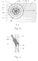
- the reference number 1 denotes a wellbore in a ground formation 2.
- a motherbore tubular 4 is positioned in the wellbore 1.
- a first non-rotating pipe 6 is passing through a collar 8 in an opening 10 in the motherbore tubular 4 and into a lateral opening 11 in the ground formation 2.
- a second non-rotating pipe 12 and a third non-rotating pipe 14 that are passing through respective collars 8 are shown in fig. 1 where only the ground formation 2 and the motherbore tubular 4 are sectioned.
- non-rotating pipes 6, 12, 14 are termed “non-rotating pipes” when the description applies to all of them.
- the non-rotating pipes 6, 12, 14 are equipped with a drill bit 18 while the non-rotating pipes 6, 12, 14 at their opposite end portion are connected to a housing 20 of a first, a second and a third fluid driven engine 22, 24, 26 respectively.
- a drill string 28 as shown in fig. 4 which extends through the first non-rotating pipe 6 connecting the drill bit 18 at the leading end portion 16, to a rotor 30 of the first fluid driven engine 22.
- the collar 8 has an angle 32 relative a centre line 34 of the motherbore tubular 4.
- the collar 8 thus directs the first non-rotating pipe 6 into the ground formation 2.
- the angle 32 may be fixed or adjustable.
- the drill bit 18 In its retracted initial position, the drill bit 18 is positioned inside the collar 8 as shown in fig. 3 .
- guides 36 may be placed in an annulus 38 between the fluid driven engines 22, 24, 26 and the motherbore tubular 4. Guides 36 will maintain the housings 20 of the fluid driven engines 22, 24, 26 in a centre position in the motherbore tubular 4 when moved along.
- the second and third non-rotating pipes 12, 14 are passing through the annulus 38 surrounding the first fluid driven engine 22. This feature allows for several fluid driven engines 22, 24, 26 to be positioned at different positions along the motherbore tubular 4.
- each annulus 38 which may form a choke relative each fluid driven engine 22, 24, 26, may be adjusted to give a desired pressure drop across the fluid driven engines 22, 24, 26.
- a simple way of achieving this is to choose a suitable length of the housing 20 combined with the actual cross section of the annulus 38. Valve systems, not shown, may also be applicable.
- the fluid driven engines 22, 24, 26 are in the form of turbine engines.
- any useful fluid driven engine may be utilized, such as vane engines, piston engines, progressive cavity engines or Archimedes engines.
- the rotor 28 may have a relatively large diameter. Necessary pressure drop across the fluid driven engines 20, 22, 24 is limited. Substantially more than three fluid driven engines 20, 22, 24, as shown in this embodiment, may be driven from the same fluid flow in the motherbore tubular 4.
- the one or more of the non-rotating pipes 6, 12, 14 may be omitted.
- the drill string 28 passes through the opening 10 in the motherbore tubular 2.
Landscapes
- Engineering & Computer Science (AREA)
- Life Sciences & Earth Sciences (AREA)
- Geology (AREA)
- Mining & Mineral Resources (AREA)
- Physics & Mathematics (AREA)
- Environmental & Geological Engineering (AREA)
- Fluid Mechanics (AREA)
- General Life Sciences & Earth Sciences (AREA)
- Geochemistry & Mineralogy (AREA)
- Mechanical Engineering (AREA)
- Earth Drilling (AREA)
- Consolidation Of Soil By Introduction Of Solidifying Substances Into Soil (AREA)
Priority Applications (12)
| Application Number | Priority Date | Filing Date | Title |
|---|---|---|---|
| EP13173376.8A EP2818626B1 (fr) | 2013-06-24 | 2013-06-24 | Procédé amélioré et dispositif de fabrication d'ouvertures latérales en dehors d'un puits de forage |
| DK13173376.8T DK2818626T3 (en) | 2013-06-24 | 2013-06-24 | An improved device for making a lateral opening out of a wellbore |
| TR2018/08624T TR201808624T4 (tr) | 2013-06-24 | 2013-06-24 | Bir kuyu deliğinden bir yanal açıklığın oluşturulmasına yönelik bir gelişmiş yöntem ve cihaz. |
| US14/890,773 US10174557B2 (en) | 2013-06-24 | 2014-06-17 | Method and device for making a lateral opening out of a wellbore |
| CN201480036103.1A CN105339582B (zh) | 2013-06-24 | 2014-06-17 | 从井眼制造出侧向开口的改进的方法和装置 |
| RU2015148925A RU2663985C2 (ru) | 2013-06-24 | 2014-06-17 | Усовершенствованный способ и устройство для выполнения бокового канала из ствола скважины |
| AU2014299404A AU2014299404B2 (en) | 2013-06-24 | 2014-06-17 | An improved method and device for making a lateral opening out of a wellbore |
| MX2015017664A MX369043B (es) | 2013-06-24 | 2014-06-17 | Metodo y dispositivo mejorados para hacer una abertura lateral fuera de un pozo. |
| CA2916969A CA2916969C (fr) | 2013-06-24 | 2014-06-17 | Procede ameliore et dispositif de realisation d'une ouverture laterale sur un puits de forage |
| BR112015032176-3A BR112015032176B1 (pt) | 2013-06-24 | 2014-06-17 | Método e dispositivo para produzir uma abertura lateral fora de um furo de poço |
| PCT/NO2014/050102 WO2014209126A1 (fr) | 2013-06-24 | 2014-06-17 | Procédé amélioré et dispositif de réalisation d'une ouverture latérale sur un puits de forage |
| SA515370297A SA515370297B1 (ar) | 2013-06-24 | 2015-12-19 | طريقة محسنة وجهاز لإحداث فتحة جانبية تصب إلى خارج حفرة بئر |
Applications Claiming Priority (1)
| Application Number | Priority Date | Filing Date | Title |
|---|---|---|---|
| EP13173376.8A EP2818626B1 (fr) | 2013-06-24 | 2013-06-24 | Procédé amélioré et dispositif de fabrication d'ouvertures latérales en dehors d'un puits de forage |
Publications (2)
| Publication Number | Publication Date |
|---|---|
| EP2818626A1 true EP2818626A1 (fr) | 2014-12-31 |
| EP2818626B1 EP2818626B1 (fr) | 2018-03-21 |
Family
ID=48740868
Family Applications (1)
| Application Number | Title | Priority Date | Filing Date |
|---|---|---|---|
| EP13173376.8A Active EP2818626B1 (fr) | 2013-06-24 | 2013-06-24 | Procédé amélioré et dispositif de fabrication d'ouvertures latérales en dehors d'un puits de forage |
Country Status (12)
| Country | Link |
|---|---|
| US (1) | US10174557B2 (fr) |
| EP (1) | EP2818626B1 (fr) |
| CN (1) | CN105339582B (fr) |
| AU (1) | AU2014299404B2 (fr) |
| BR (1) | BR112015032176B1 (fr) |
| CA (1) | CA2916969C (fr) |
| DK (1) | DK2818626T3 (fr) |
| MX (1) | MX369043B (fr) |
| RU (1) | RU2663985C2 (fr) |
| SA (1) | SA515370297B1 (fr) |
| TR (1) | TR201808624T4 (fr) |
| WO (1) | WO2014209126A1 (fr) |
Cited By (8)
| Publication number | Priority date | Publication date | Assignee | Title |
|---|---|---|---|---|
| CN106988686A (zh) * | 2016-01-20 | 2017-07-28 | 中国石油化工股份有限公司 | 管柱 |
| CN107288547A (zh) * | 2016-04-01 | 2017-10-24 | 中国石油化工股份有限公司 | 一种井下钻孔装置 |
| CN107461151A (zh) * | 2016-06-02 | 2017-12-12 | 中国石油化工股份有限公司 | 羽状分支井的静压侧钻装置及改造方法 |
| CN107461152A (zh) * | 2016-06-02 | 2017-12-12 | 中国石油化工股份有限公司 | 分支井侧钻装置及分支井侧钻方法 |
| GB2561072A (en) * | 2014-06-22 | 2018-10-03 | Octopus Completions Ltd | Lateral drilling system |
| US10995563B2 (en) | 2017-01-18 | 2021-05-04 | Minex Crc Ltd | Rotary drill head for coiled tubing drilling apparatus |
| US11268362B2 (en) | 2020-02-10 | 2022-03-08 | Conocophillips Company | Hydrocarbon production through creation of collapsable cavities by acid placement through lateral conduits |
| WO2024129431A1 (fr) * | 2022-12-12 | 2024-06-20 | Saudi Arabian Oil Company | Stimulation hyper-ramifiée en combinant un creusement de tunnels de réservoir avec des aiguilles étendues |
Families Citing this family (6)
| Publication number | Priority date | Publication date | Assignee | Title |
|---|---|---|---|---|
| CN107461186B (zh) * | 2016-06-02 | 2020-02-18 | 中国石油化工股份有限公司 | 分支井储层改造装置及改造方法 |
| US11149497B2 (en) * | 2016-10-24 | 2021-10-19 | Rival Downhole Tools Lc | Drilling motor with bypass and method |
| US10519737B2 (en) * | 2017-11-29 | 2019-12-31 | Baker Hughes, A Ge Company, Llc | Place-n-perf |
| CN110344755A (zh) * | 2019-06-19 | 2019-10-18 | 中国海洋石油集团有限公司 | 一种涡轮钻进式多分支小井眼完井工具及操作方法 |
| CN112983260A (zh) * | 2021-03-04 | 2021-06-18 | 周拯 | 一种复合冲击防掉钻井提速器 |
| NO346972B1 (en) | 2021-06-03 | 2023-03-20 | Fishbones AS | Apparatus for forming lateral bores in subsurface rock formations, and wellbore string |
Citations (5)
| Publication number | Priority date | Publication date | Assignee | Title |
|---|---|---|---|---|
| US5853056A (en) * | 1993-10-01 | 1998-12-29 | Landers; Carl W. | Method of and apparatus for horizontal well drilling |
| WO2002086278A1 (fr) * | 2001-04-23 | 2002-10-31 | Shell Internationale Research Maatschappij B.V. | Procede pour realiser un trou de forage d'un rayon tres petit |
| EP2098679A1 (fr) | 2008-03-06 | 2009-09-09 | Rune Freyer | Procédé et dispositif de fabrication d'ouvertures latérales en dehors d'un puits de forage |
| US20110005834A1 (en) * | 2009-07-07 | 2011-01-13 | Crawford James R | Method to control bit load |
| WO2012105850A1 (fr) | 2011-02-03 | 2012-08-09 | Fishbones AS | Procédé et dispositif pour déployer un câble et un appareil dans le sol |
Family Cites Families (10)
| Publication number | Priority date | Publication date | Assignee | Title |
|---|---|---|---|---|
| FR2091931B1 (fr) * | 1970-05-15 | 1973-08-10 | Petroles Cie Francaise | |
| US4007797A (en) * | 1974-06-04 | 1977-02-15 | Texas Dynamatics, Inc. | Device for drilling a hole in the side wall of a bore hole |
| US4432423A (en) * | 1979-12-31 | 1984-02-21 | Lyons William C | Apparatus for extended straight line drilling from a curved borehole |
| RU2347095C1 (ru) * | 2007-06-05 | 2009-02-20 | Эдуард Дмитриевич Житников | Крейцкопфный поршень с опорным колпаком |
| WO2009055380A2 (fr) * | 2007-10-22 | 2009-04-30 | Radjet Llc | Appareil et procédé pour forer un cuvelage dans des applications de forage hydrodynamique pour la production d'hydrocarbures |
| US8770316B2 (en) * | 2008-05-20 | 2014-07-08 | Radial Drilling Services, Inc. | Method and apparatus for high pressure radial pulsed jetting of lateral passages from vertical to horizontal wellbores |
| CN201507239U (zh) * | 2009-05-10 | 2010-06-16 | 曹汉江 | 一种涡轮转子定子 |
| CN102619466A (zh) * | 2011-01-31 | 2012-08-01 | 中国石油化工集团公司 | 一种旋转偏心式套管内钻孔装置 |
| CN102454423A (zh) * | 2011-11-30 | 2012-05-16 | 中国船舶重工集团公司第七�三研究所 | 涡轮定子和转子组合件 |
| CN103015889A (zh) * | 2012-12-20 | 2013-04-03 | 中国船舶重工集团公司第七�三研究所 | 大功率高速高效涡轮钻具定子和转子组合件 |
-
2013
- 2013-06-24 DK DK13173376.8T patent/DK2818626T3/en active
- 2013-06-24 TR TR2018/08624T patent/TR201808624T4/tr unknown
- 2013-06-24 EP EP13173376.8A patent/EP2818626B1/fr active Active
-
2014
- 2014-06-17 CA CA2916969A patent/CA2916969C/fr active Active
- 2014-06-17 US US14/890,773 patent/US10174557B2/en active Active
- 2014-06-17 RU RU2015148925A patent/RU2663985C2/ru active
- 2014-06-17 CN CN201480036103.1A patent/CN105339582B/zh active Active
- 2014-06-17 WO PCT/NO2014/050102 patent/WO2014209126A1/fr not_active Ceased
- 2014-06-17 BR BR112015032176-3A patent/BR112015032176B1/pt active IP Right Grant
- 2014-06-17 AU AU2014299404A patent/AU2014299404B2/en active Active
- 2014-06-17 MX MX2015017664A patent/MX369043B/es active IP Right Grant
-
2015
- 2015-12-19 SA SA515370297A patent/SA515370297B1/ar unknown
Patent Citations (5)
| Publication number | Priority date | Publication date | Assignee | Title |
|---|---|---|---|---|
| US5853056A (en) * | 1993-10-01 | 1998-12-29 | Landers; Carl W. | Method of and apparatus for horizontal well drilling |
| WO2002086278A1 (fr) * | 2001-04-23 | 2002-10-31 | Shell Internationale Research Maatschappij B.V. | Procede pour realiser un trou de forage d'un rayon tres petit |
| EP2098679A1 (fr) | 2008-03-06 | 2009-09-09 | Rune Freyer | Procédé et dispositif de fabrication d'ouvertures latérales en dehors d'un puits de forage |
| US20110005834A1 (en) * | 2009-07-07 | 2011-01-13 | Crawford James R | Method to control bit load |
| WO2012105850A1 (fr) | 2011-02-03 | 2012-08-09 | Fishbones AS | Procédé et dispositif pour déployer un câble et un appareil dans le sol |
Cited By (11)
| Publication number | Priority date | Publication date | Assignee | Title |
|---|---|---|---|---|
| GB2561072A (en) * | 2014-06-22 | 2018-10-03 | Octopus Completions Ltd | Lateral drilling system |
| GB2561072B (en) * | 2014-06-22 | 2019-05-08 | Octopus Completions Ltd | Lateral drilling system |
| CN106988686A (zh) * | 2016-01-20 | 2017-07-28 | 中国石油化工股份有限公司 | 管柱 |
| CN107288547A (zh) * | 2016-04-01 | 2017-10-24 | 中国石油化工股份有限公司 | 一种井下钻孔装置 |
| CN107461151A (zh) * | 2016-06-02 | 2017-12-12 | 中国石油化工股份有限公司 | 羽状分支井的静压侧钻装置及改造方法 |
| CN107461152A (zh) * | 2016-06-02 | 2017-12-12 | 中国石油化工股份有限公司 | 分支井侧钻装置及分支井侧钻方法 |
| CN107461152B (zh) * | 2016-06-02 | 2019-10-11 | 中国石油化工股份有限公司 | 分支井侧钻装置及分支井侧钻方法 |
| US10995563B2 (en) | 2017-01-18 | 2021-05-04 | Minex Crc Ltd | Rotary drill head for coiled tubing drilling apparatus |
| US11136837B2 (en) | 2017-01-18 | 2021-10-05 | Minex Crc Ltd | Mobile coiled tubing drilling apparatus |
| US11268362B2 (en) | 2020-02-10 | 2022-03-08 | Conocophillips Company | Hydrocarbon production through creation of collapsable cavities by acid placement through lateral conduits |
| WO2024129431A1 (fr) * | 2022-12-12 | 2024-06-20 | Saudi Arabian Oil Company | Stimulation hyper-ramifiée en combinant un creusement de tunnels de réservoir avec des aiguilles étendues |
Also Published As
| Publication number | Publication date |
|---|---|
| MX2015017664A (es) | 2016-06-23 |
| EP2818626B1 (fr) | 2018-03-21 |
| DK2818626T3 (en) | 2018-06-25 |
| US10174557B2 (en) | 2019-01-08 |
| US20160097239A1 (en) | 2016-04-07 |
| CA2916969C (fr) | 2020-12-15 |
| RU2015148925A (ru) | 2017-07-28 |
| MX369043B (es) | 2019-10-25 |
| BR112015032176A2 (pt) | 2017-07-25 |
| TR201808624T4 (tr) | 2018-07-23 |
| CA2916969A1 (fr) | 2014-12-31 |
| CN105339582B (zh) | 2019-01-15 |
| AU2014299404A1 (en) | 2015-12-03 |
| CN105339582A (zh) | 2016-02-17 |
| RU2663985C2 (ru) | 2018-08-14 |
| BR112015032176A8 (pt) | 2022-04-12 |
| AU2014299404B2 (en) | 2016-05-26 |
| SA515370297B1 (ar) | 2020-01-23 |
| WO2014209126A1 (fr) | 2014-12-31 |
| BR112015032176B1 (pt) | 2023-02-14 |
Similar Documents
| Publication | Publication Date | Title |
|---|---|---|
| EP2818626B1 (fr) | Procédé amélioré et dispositif de fabrication d'ouvertures latérales en dehors d'un puits de forage | |
| EP2098679B1 (fr) | Procédé et dispositif de fabrication d'ouvertures latérales en dehors d'un puits de forage | |
| AU2011349330B2 (en) | Method and apparatus for drilling a zero-radius lateral | |
| EP3143240B1 (fr) | Outil de penetration tubulaire de puits de forage multifonction | |
| US10287829B2 (en) | Method and apparatus to rotate subsurface wellbore casing | |
| EP1222356B1 (fr) | Procede et dispositif permettant de deplacer un tube dans un trou de forage dans le sol | |
| US20160194917A1 (en) | Axial Oscillation Device | |
| RU2016135929A (ru) | Управление торцом долота скважинного инструмента с уменьшенным трением бурильной колонны | |
| CN107489405B (zh) | 连续油管拖动喷砂射孔与环空填砂分段压裂的方法 | |
| CN114233194B (zh) | 一种煤矿井下分体式水力造斜钻具组合及钻进方法 | |
| US20010011591A1 (en) | Guide device | |
| US9080384B2 (en) | Pressure balanced fluid operated reaming tool for use in placing wellbore tubulars | |
| US10907421B2 (en) | Drill string applications tool | |
| CN201802366U (zh) | 高压喷射侧钻小井眼工具装置 | |
| US11125020B2 (en) | Downhole drilling apparatus with drilling, steering, and reaming functions and methods of use | |
| EP1588021B1 (fr) | Procede et dispositif de perforation d'elements tubulaires places les uns a l'interieur des autres | |
| EP3516310B1 (fr) | Sonde géothermique coaxiale et procédé de fabrication d'une sonde géothermique coaxiale | |
| EP3227526B1 (fr) | Système d'exécution de fond de trou | |
| RU173662U1 (ru) | Устройство для бурения на экспандируемых трубах локального крепления скважин | |
| AU2004204324B2 (en) | A method and device for drilling into tubulars located within one another | |
| CN203488101U (zh) | 油井智能钻孔设备 |
Legal Events
| Date | Code | Title | Description |
|---|---|---|---|
| PUAI | Public reference made under article 153(3) epc to a published international application that has entered the european phase |
Free format text: ORIGINAL CODE: 0009012 |
|
| 17P | Request for examination filed |
Effective date: 20130624 |
|
| AK | Designated contracting states |
Kind code of ref document: A1 Designated state(s): AL AT BE BG CH CY CZ DE DK EE ES FI FR GB GR HR HU IE IS IT LI LT LU LV MC MK MT NL NO PL PT RO RS SE SI SK SM TR |
|
| AX | Request for extension of the european patent |
Extension state: BA ME |
|
| R17P | Request for examination filed (corrected) |
Effective date: 20130624 |
|
| 17Q | First examination report despatched |
Effective date: 20161020 |
|
| REG | Reference to a national code |
Ref country code: DE Ref legal event code: R079 Ref document number: 602013034610 Country of ref document: DE Free format text: PREVIOUS MAIN CLASS: E21B0023080000 Ipc: E21B0003000000 |
|
| GRAP | Despatch of communication of intention to grant a patent |
Free format text: ORIGINAL CODE: EPIDOSNIGR1 |
|
| RIC1 | Information provided on ipc code assigned before grant |
Ipc: E21B 4/02 20060101ALI20170925BHEP Ipc: E21B 4/16 20060101ALI20170925BHEP Ipc: E21B 7/06 20060101ALI20170925BHEP Ipc: E21B 3/00 20060101AFI20170925BHEP Ipc: E21B 7/04 20060101ALI20170925BHEP Ipc: E21B 41/00 20060101ALI20170925BHEP Ipc: E21B 23/08 20060101ALI20170925BHEP Ipc: E21B 43/26 20060101ALI20170925BHEP |
|
| INTG | Intention to grant announced |
Effective date: 20171031 |
|
| GRAS | Grant fee paid |
Free format text: ORIGINAL CODE: EPIDOSNIGR3 |
|
| GRAA | (expected) grant |
Free format text: ORIGINAL CODE: 0009210 |
|
| AK | Designated contracting states |
Kind code of ref document: B1 Designated state(s): AL AT BE BG CH CY CZ DE DK EE ES FI FR GB GR HR HU IE IS IT LI LT LU LV MC MK MT NL NO PL PT RO RS SE SI SK SM TR |
|
| REG | Reference to a national code |
Ref country code: GB Ref legal event code: FG4D |
|
| REG | Reference to a national code |
Ref country code: CH Ref legal event code: EP |
|
| REG | Reference to a national code |
Ref country code: AT Ref legal event code: REF Ref document number: 981307 Country of ref document: AT Kind code of ref document: T Effective date: 20180415 |
|
| REG | Reference to a national code |
Ref country code: IE Ref legal event code: FG4D |
|
| REG | Reference to a national code |
Ref country code: DE Ref legal event code: R096 Ref document number: 602013034610 Country of ref document: DE |
|
| REG | Reference to a national code |
Ref country code: FR Ref legal event code: PLFP Year of fee payment: 6 |
|
| REG | Reference to a national code |
Ref country code: RO Ref legal event code: EPE |
|
| REG | Reference to a national code |
Ref country code: DK Ref legal event code: T3 Effective date: 20180618 |
|
| REG | Reference to a national code |
Ref country code: NL Ref legal event code: FP |
|
| RAP2 | Party data changed (patent owner data changed or rights of a patent transferred) |
Owner name: FISHBONES AS |
|
| PG25 | Lapsed in a contracting state [announced via postgrant information from national office to epo] |
Ref country code: HR Free format text: LAPSE BECAUSE OF FAILURE TO SUBMIT A TRANSLATION OF THE DESCRIPTION OR TO PAY THE FEE WITHIN THE PRESCRIBED TIME-LIMIT Effective date: 20180321 Ref country code: FI Free format text: LAPSE BECAUSE OF FAILURE TO SUBMIT A TRANSLATION OF THE DESCRIPTION OR TO PAY THE FEE WITHIN THE PRESCRIBED TIME-LIMIT Effective date: 20180321 Ref country code: LT Free format text: LAPSE BECAUSE OF FAILURE TO SUBMIT A TRANSLATION OF THE DESCRIPTION OR TO PAY THE FEE WITHIN THE PRESCRIBED TIME-LIMIT Effective date: 20180321 Ref country code: CY Free format text: LAPSE BECAUSE OF FAILURE TO SUBMIT A TRANSLATION OF THE DESCRIPTION OR TO PAY THE FEE WITHIN THE PRESCRIBED TIME-LIMIT Effective date: 20180321 |
|
| REG | Reference to a national code |
Ref country code: LT Ref legal event code: MG4D |
|
| REG | Reference to a national code |
Ref country code: AT Ref legal event code: MK05 Ref document number: 981307 Country of ref document: AT Kind code of ref document: T Effective date: 20180321 |
|
| REG | Reference to a national code |
Ref country code: NO Ref legal event code: T2 Effective date: 20180321 |
|
| PG25 | Lapsed in a contracting state [announced via postgrant information from national office to epo] |
Ref country code: LV Free format text: LAPSE BECAUSE OF FAILURE TO SUBMIT A TRANSLATION OF THE DESCRIPTION OR TO PAY THE FEE WITHIN THE PRESCRIBED TIME-LIMIT Effective date: 20180321 Ref country code: RS Free format text: LAPSE BECAUSE OF FAILURE TO SUBMIT A TRANSLATION OF THE DESCRIPTION OR TO PAY THE FEE WITHIN THE PRESCRIBED TIME-LIMIT Effective date: 20180321 Ref country code: SE Free format text: LAPSE BECAUSE OF FAILURE TO SUBMIT A TRANSLATION OF THE DESCRIPTION OR TO PAY THE FEE WITHIN THE PRESCRIBED TIME-LIMIT Effective date: 20180321 Ref country code: GR Free format text: LAPSE BECAUSE OF FAILURE TO SUBMIT A TRANSLATION OF THE DESCRIPTION OR TO PAY THE FEE WITHIN THE PRESCRIBED TIME-LIMIT Effective date: 20180622 Ref country code: BG Free format text: LAPSE BECAUSE OF FAILURE TO SUBMIT A TRANSLATION OF THE DESCRIPTION OR TO PAY THE FEE WITHIN THE PRESCRIBED TIME-LIMIT Effective date: 20180621 |
|
| PG25 | Lapsed in a contracting state [announced via postgrant information from national office to epo] |
Ref country code: EE Free format text: LAPSE BECAUSE OF FAILURE TO SUBMIT A TRANSLATION OF THE DESCRIPTION OR TO PAY THE FEE WITHIN THE PRESCRIBED TIME-LIMIT Effective date: 20180321 Ref country code: PL Free format text: LAPSE BECAUSE OF FAILURE TO SUBMIT A TRANSLATION OF THE DESCRIPTION OR TO PAY THE FEE WITHIN THE PRESCRIBED TIME-LIMIT Effective date: 20180321 Ref country code: ES Free format text: LAPSE BECAUSE OF FAILURE TO SUBMIT A TRANSLATION OF THE DESCRIPTION OR TO PAY THE FEE WITHIN THE PRESCRIBED TIME-LIMIT Effective date: 20180321 Ref country code: AL Free format text: LAPSE BECAUSE OF FAILURE TO SUBMIT A TRANSLATION OF THE DESCRIPTION OR TO PAY THE FEE WITHIN THE PRESCRIBED TIME-LIMIT Effective date: 20180321 |
|
| PG25 | Lapsed in a contracting state [announced via postgrant information from national office to epo] |
Ref country code: SM Free format text: LAPSE BECAUSE OF FAILURE TO SUBMIT A TRANSLATION OF THE DESCRIPTION OR TO PAY THE FEE WITHIN THE PRESCRIBED TIME-LIMIT Effective date: 20180321 Ref country code: SK Free format text: LAPSE BECAUSE OF FAILURE TO SUBMIT A TRANSLATION OF THE DESCRIPTION OR TO PAY THE FEE WITHIN THE PRESCRIBED TIME-LIMIT Effective date: 20180321 Ref country code: CZ Free format text: LAPSE BECAUSE OF FAILURE TO SUBMIT A TRANSLATION OF THE DESCRIPTION OR TO PAY THE FEE WITHIN THE PRESCRIBED TIME-LIMIT Effective date: 20180321 Ref country code: AT Free format text: LAPSE BECAUSE OF FAILURE TO SUBMIT A TRANSLATION OF THE DESCRIPTION OR TO PAY THE FEE WITHIN THE PRESCRIBED TIME-LIMIT Effective date: 20180321 |
|
| PG25 | Lapsed in a contracting state [announced via postgrant information from national office to epo] |
Ref country code: PT Free format text: LAPSE BECAUSE OF FAILURE TO SUBMIT A TRANSLATION OF THE DESCRIPTION OR TO PAY THE FEE WITHIN THE PRESCRIBED TIME-LIMIT Effective date: 20180723 |
|
| REG | Reference to a national code |
Ref country code: DE Ref legal event code: R097 Ref document number: 602013034610 Country of ref document: DE |
|
| PLBE | No opposition filed within time limit |
Free format text: ORIGINAL CODE: 0009261 |
|
| STAA | Information on the status of an ep patent application or granted ep patent |
Free format text: STATUS: NO OPPOSITION FILED WITHIN TIME LIMIT |
|
| REG | Reference to a national code |
Ref country code: CH Ref legal event code: PL |
|
| 26N | No opposition filed |
Effective date: 20190102 |
|
| REG | Reference to a national code |
Ref country code: BE Ref legal event code: MM Effective date: 20180630 |
|
| PG25 | Lapsed in a contracting state [announced via postgrant information from national office to epo] |
Ref country code: LU Free format text: LAPSE BECAUSE OF NON-PAYMENT OF DUE FEES Effective date: 20180624 Ref country code: MC Free format text: LAPSE BECAUSE OF FAILURE TO SUBMIT A TRANSLATION OF THE DESCRIPTION OR TO PAY THE FEE WITHIN THE PRESCRIBED TIME-LIMIT Effective date: 20180321 |
|
| PG25 | Lapsed in a contracting state [announced via postgrant information from national office to epo] |
Ref country code: LI Free format text: LAPSE BECAUSE OF NON-PAYMENT OF DUE FEES Effective date: 20180630 Ref country code: CH Free format text: LAPSE BECAUSE OF NON-PAYMENT OF DUE FEES Effective date: 20180630 |
|
| PG25 | Lapsed in a contracting state [announced via postgrant information from national office to epo] |
Ref country code: SI Free format text: LAPSE BECAUSE OF FAILURE TO SUBMIT A TRANSLATION OF THE DESCRIPTION OR TO PAY THE FEE WITHIN THE PRESCRIBED TIME-LIMIT Effective date: 20180321 Ref country code: BE Free format text: LAPSE BECAUSE OF NON-PAYMENT OF DUE FEES Effective date: 20180630 |
|
| PG25 | Lapsed in a contracting state [announced via postgrant information from national office to epo] |
Ref country code: MT Free format text: LAPSE BECAUSE OF NON-PAYMENT OF DUE FEES Effective date: 20180624 |
|
| PG25 | Lapsed in a contracting state [announced via postgrant information from national office to epo] |
Ref country code: HU Free format text: LAPSE BECAUSE OF FAILURE TO SUBMIT A TRANSLATION OF THE DESCRIPTION OR TO PAY THE FEE WITHIN THE PRESCRIBED TIME-LIMIT; INVALID AB INITIO Effective date: 20130624 |
|
| PG25 | Lapsed in a contracting state [announced via postgrant information from national office to epo] |
Ref country code: MK Free format text: LAPSE BECAUSE OF NON-PAYMENT OF DUE FEES Effective date: 20180321 |
|
| PG25 | Lapsed in a contracting state [announced via postgrant information from national office to epo] |
Ref country code: IS Free format text: LAPSE BECAUSE OF FAILURE TO SUBMIT A TRANSLATION OF THE DESCRIPTION OR TO PAY THE FEE WITHIN THE PRESCRIBED TIME-LIMIT Effective date: 20180721 |
|
| P01 | Opt-out of the competence of the unified patent court (upc) registered |
Effective date: 20230524 |
|
| PGFP | Annual fee paid to national office [announced via postgrant information from national office to epo] |
Ref country code: DE Payment date: 20250623 Year of fee payment: 13 |
|
| PGFP | Annual fee paid to national office [announced via postgrant information from national office to epo] |
Ref country code: GB Payment date: 20250610 Year of fee payment: 13 Ref country code: DK Payment date: 20250612 Year of fee payment: 13 |
|
| PGFP | Annual fee paid to national office [announced via postgrant information from national office to epo] |
Ref country code: NO Payment date: 20250610 Year of fee payment: 13 |
|
| PGFP | Annual fee paid to national office [announced via postgrant information from national office to epo] |
Ref country code: NL Payment date: 20250620 Year of fee payment: 13 |
|
| PGFP | Annual fee paid to national office [announced via postgrant information from national office to epo] |
Ref country code: FR Payment date: 20250612 Year of fee payment: 13 |
|
| PGFP | Annual fee paid to national office [announced via postgrant information from national office to epo] |
Ref country code: RO Payment date: 20250528 Year of fee payment: 13 |
|
| PGFP | Annual fee paid to national office [announced via postgrant information from national office to epo] |
Ref country code: TR Payment date: 20250522 Year of fee payment: 13 |
|
| PGFP | Annual fee paid to national office [announced via postgrant information from national office to epo] |
Ref country code: IE Payment date: 20250612 Year of fee payment: 13 |
|
| PGFP | Annual fee paid to national office [announced via postgrant information from national office to epo] |
Ref country code: IT Payment date: 20250617 Year of fee payment: 13 |