EP2818612B1 - Locking component - Google Patents
Locking component Download PDFInfo
- Publication number
- EP2818612B1 EP2818612B1 EP14171277.8A EP14171277A EP2818612B1 EP 2818612 B1 EP2818612 B1 EP 2818612B1 EP 14171277 A EP14171277 A EP 14171277A EP 2818612 B1 EP2818612 B1 EP 2818612B1
- Authority
- EP
- European Patent Office
- Prior art keywords
- keyhole
- securing component
- opening
- contact surface
- component according
- Prior art date
- Legal status (The legal status is an assumption and is not a legal conclusion. Google has not performed a legal analysis and makes no representation as to the accuracy of the status listed.)
- Active
Links
- 230000002093 peripheral effect Effects 0.000 claims description 15
- 239000004033 plastic Substances 0.000 claims description 6
- 229920003023 plastic Polymers 0.000 claims description 6
- 239000000463 material Substances 0.000 claims description 3
- 239000002991 molded plastic Substances 0.000 claims 1
- 238000003780 insertion Methods 0.000 description 9
- 230000037431 insertion Effects 0.000 description 9
- 238000002347 injection Methods 0.000 description 4
- 239000007924 injection Substances 0.000 description 4
- 230000006835 compression Effects 0.000 description 1
- 238000007906 compression Methods 0.000 description 1
- 230000006378 damage Effects 0.000 description 1
- 230000012447 hatching Effects 0.000 description 1
- 230000035515 penetration Effects 0.000 description 1
Images


Classifications
-
- E—FIXED CONSTRUCTIONS
- E05—LOCKS; KEYS; WINDOW OR DOOR FITTINGS; SAFES
- E05B—LOCKS; ACCESSORIES THEREFOR; HANDCUFFS
- E05B11/00—Devices preventing keys from being removed from the lock ; Devices preventing falling or pushing out of keys
-
- E—FIXED CONSTRUCTIONS
- E05—LOCKS; KEYS; WINDOW OR DOOR FITTINGS; SAFES
- E05B—LOCKS; ACCESSORIES THEREFOR; HANDCUFFS
- E05B17/00—Accessories in connection with locks
- E05B17/14—Closures or guards for keyholes
Landscapes
- Injection Moulding Of Plastics Or The Like (AREA)
- Lock And Its Accessories (AREA)
- Snaps, Bayonet Connections, Set Pins, And Snap Rings (AREA)
Description
Die Erfindung betrifft ein in ein Schlüsselloch eines Schlosses für einen Bartschlüssel einsetzbares einteiliges, sich am Schlüsselloch selbst halterndes Sicherungsteil nach den Merkmalen des Oberbegriffes des Anspruches 1
Aus der
Ausgehend von dem dargelegten Stand der Technik beschäftigt sich die Erfindung mit der Aufgabenstellung, ein Sicherungsteil für ein Schlüsselloch eines Schlosses, das für einen Bartschlüssel ausgelegt ist, anzugeben, das bei möglichst einfachem Aufbau eine zuverlässige Sicherung erreichen lässt.
Diese Aufgabe ist beim Gegenstand des Anspruches 1 gelöst, wobei darauf abgestellt ist, dass eine Öffnung vorgesehen ist, die schlüssellochartig ausgebildet ist, mit einem oberen Rundbereich und einem unteren lang gestreckten Bereich und dass das Sicherungsteil zur Entfernung aus und/oder Einbringung in das Schlüsselloch in Richtung zweier sich in Bezug auf die Öffnung gegenüberliegender Abschnitte des Randteils zusammenzudrücken ist.
Hinsichtlich der U-förmigen Ausbildung ist der die Auflagefläche bildende Bereich ein U-Schenkel.The invention relates to an insertable into a keyhole of a lock for a beard key one-piece, on the keyhole self-retaining part according to the features of the preamble of
From the
Based on the stated prior art, the invention is concerned with the task of specifying a securing part for a keyhole of a lock, which is designed for a beard key, which can achieve a reliable backup with the simplest possible structure.
This object is achieved in the subject matter of
With regard to the U-shaped configuration of the support surface forming area is a U-leg.
Das Sicherungsteil kann insgesamt als Flachteil ausgebildet sein. Die - gegebenenfalls längste - Erstreckung in Richtung der Auflagefläche ist bevorzugt 1,5-bis 3-Mal, weiter bevorzugt 2-Mal so groß wie die Erstreckung senkrecht dazu. Es bedarf keiner gewölbeartigen Struktur. Es ist auch keine gewölbeartige Struktur vorgesehen. Hierbei kann gegeben sein, wobei dies auch eine bevorzugte Ausgestaltung darstellt, dass ein eingesetztes Sicherungsteil mit Handkraft alleine, jedenfalls nicht mit der Handkraft eines Kindes, nicht wieder entfernbar ist. Dies ermöglicht es, einem ungewollten Entfernen des Sicherungsteils aus dem Schlüsselloch vorzubeugen.The securing part may be formed overall as a flat part. The - possibly longest - extent in the direction of the support surface is preferably 1.5 to 3 times, more preferably 2 times as large as the extent perpendicular thereto. It does not require a vault-like structure. There is also no vault-like structure provided. This can be given, which also represents a preferred embodiment that an inserted security part with hand force alone, at least not with the hand of a child, not removable again. This makes it possible to prevent unwanted removal of the securing part from the keyhole.
Zugleich ist auch die Auflagefläche für ein definiertes tiefenmäßiges Eindringen des Sicherungsteils in das Schlüsselloch vorteilhaft. Über die Auflagefläche hinaus kann das Sicherungsteil nicht in das Schlüsselloch eingesteckt werden.At the same time, the support surface for a defined deep penetration of the security part in the keyhole is advantageous. Beyond the bearing surface, the securing part can not be inserted into the keyhole.
Es ist bevorzugt, dass das Randteil ringartig geschlossen umlaufend ausgebildet ist. Es kann grundsätzlich auch nur U-förmig verlaufend ausgebildet sein. Die ringartig geschlossene Ausbildung ermöglicht aber insbesondere nochmals eine steifere Ausgestaltung des Sicherungsteils insgesamt, und damit das Erreichen des bereits prinzipiell angesprochenen Schutzes gegen unbeabsichtiges oder nicht gewolltes Entfernen aus dem Schlüsselloch.It is preferred that the edge part is formed annularly closed circumferentially. It may in principle be formed only U-shaped extending. The ring-like closed training, however, makes it possible in particular once again a stiffer configuration of the security part as a whole, and thus the achievement of the already in principle addressed protection against unintentional or unwanted removal from the keyhole.
Der Umgreifungsabschnitt ist bevorzugt nur auf einer Teillänge des Randteils ausgebildet. Weiter bevorzugt sind zwei Umgreifungsabschnitte, darüber hinaus bevorzugt gegenüberliegend bezüglich Abschnitten des Randteils, ausgebildet. Im Hinblick auf eine Längserstreckung des Sicherungsteils, die an die Längserstreckung des Schlüsselloches bevorzugt angepasst ist, sind die Umgreifungsabschnitte etwa in einem mittleren Bereich bevorzugt ausgebildet.The encompassing portion is preferably formed only on a partial length of the edge portion. More preferably, two Umgreifungsabschnitte, moreover, preferably opposite with respect to portions of the edge portion is formed. With regard to a longitudinal extension of the securing part, which is preferably adapted to the longitudinal extension of the keyhole, the embracing sections are preferably formed approximately in a middle region.
Im Falle eines ringartig geschlossen umlaufenden Randteiles ist auch bevorzugt, dass die Auflagefläche durchgehend umlaufend ausgebildet ist. Ansonsten ist bevorzugt, dass die Auflagefläche jedenfalls über die gesamte Länge des Sicherungsteils ausgebildet ist.In the case of an annularly closed peripheral edge part is also preferred that the support surface is formed continuously encircling. Otherwise, it is preferred that the bearing surface is in any case formed over the entire length of the securing part.
Die Auflagefläche kann durch Auflagenoppen oder sonstige Vorsprünge gebildet sein. Bevorzugt ist jedoch, dass sie ebenflächig ausgebildet ist.
Für das Sicherungsteil insgesamt ist bevorzugt, dass es ein Kunststoff-Spritzteil ist. Hierbei kann das Sicherungsteil auch aus einem Hartkunststoff bestehen, der nur insoweit eine ausreichende Elastizität aufweisen muss, als das Zusammendrücken des Randteils in der Öffnungsebene, um die Umgreifungsabschnitte aus dem Übergriff zu lösen, ohne Zerstörung aufnehmbar sein muss. In Einzelfällen kann aber auch vorgesehen sein, etwa bei einer Erstausrüstung eines derartigen Schlosses oder dergleichen, dass das Sicherungsteil durch das Entfernen einen Aufbruch erfährt.The support surface may be formed by support knobs or other projections. However, it is preferred that it is formed planar.
For the security part as a whole it is preferred that it is a plastic injection molded part. Here, the securing part may also consist of a hard plastic, which only to the extent must have sufficient elasticity, as the compression of the edge portion in the opening plane to solve the Umgreifungsabschnitte from the encroachment, without destruction must be accommodated. In individual cases, however, can also be provided, such as original equipment such a lock or the like, that the securing part undergoes a departure by the removal.
Erfindungsgemäß ist das Sicherungsteil zur Entfernung aus und/oder einem Einbringen in das Schlüsselloch in Richtung zweier sich in Bezug auf die Öffnung gegenüberliegende Abschnitte des Randteils zusammenzudrücken. Bei der bevorzugten Gestaltung als Randteil eines Langloches sind die gegenüberliegenden Abschnitte - bezogen auf eine solche Längserstreckung - bevorzugt mittig gegeben.According to the invention, the securing part for removal from and / or insertion into the keyhole is to be compressed in the direction of two sections of the edge part which are opposite one another with respect to the opening. In the preferred design as a peripheral part of a slot, the opposite sections - with respect to such a longitudinal extent - preferably given in the middle.
Eine Abmessung des Sicherungsteils quer zu einer Öffnungsebene, also in Einsteckrichtung eines Schlüssels, ist bevorzugt gering, etwa dem 0,5- bis 2-Fachen, bevorzugt dem 1,1-Fachen einer Öffnungsbereite der Öffnung in ihrer geringsten Breite entsprechend.A dimension of the securing part transversely to an opening plane, that is to say in the insertion direction of a key, is preferably small, approximately 0.5 to 2 times, preferably 1.1 times, an opening width of the opening in its smallest width.
Die Öffnungsfläche der Öffnung selbst läuft bevorzugt durch eine der Auflagefläche gegenüberliegende Randkante des Randteils, wobei weiter bevorzugt diese Randkante auch die in Auszugsrichtung des Schlüssels höchste Erhebung mit darstellt.The opening area of the opening itself preferably runs through a peripheral edge of the edge part lying opposite the support surface, whereby this peripheral edge also preferably represents the highest elevation in the extension direction of the key.
Nachstehend ist die Erfindung des Weiteren anhand der beigefügten Zeichnung, die jedoch lediglich ein Ausführungsbeispiel darstellt, erläutert. Hierbei zeigt:
- Fig. 1
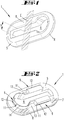
- eine perspektivische Ansicht von schräg oben des Sicherungsteils;
- Fig. 2
- eine Ansicht gemäß
Figur 1 - Fig. 3
- eine Draufsicht;
- Fig. 4
- ein Schnitt durch den Gegenstand gemäß
Figur 3Figur 3 - Fig. 5
- eine Seitenansicht der Schmalseite;
- Fig. 6
- eine Unteransicht mit angedeutetem Schlüssel und Schlüsselloch; und
- Fig 7
- eine schematische Querschnittsansicht eines Schlosses mit Schlüsselloch, eingesetztem Bartschlüssel und Sicherungsteil.
- Fig. 1
- a perspective view obliquely from above of the securing part;
- Fig. 2
- a view according to
FIG. 1 seen from diagonally below; - Fig. 3
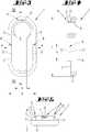
- a plan view;
- Fig. 4
- a section through the article according to
FIG. 3 , cut in the plane IV-IV inFIG. 3 ; - Fig. 5
- a side view of the narrow side;
- Fig. 6
- a bottom view with indicated key and keyhole; and
- Fig. 7
- a schematic cross-sectional view of a lock with keyhole, inserted beard key and security part.
Dargestellt und beschrieben ist ein Sicherungsteil 1, das als einstückiges Kunststoff-Spritzteil dargestellt ist.Shown and described is a
Wie etwa aus
Das Sicherungsteil 1 ist im Wesentlichen allein durch ein Randteil 5 gegeben, das eine Öffnung 6 mit einer Öffnungsebene E begrenzt (siehe schematische Andeutung in
Unterseitig, d.h. einsteckseitig des Schlüsselloches 2 weist das Sicherungsteil beziehungsweise konkret das Randteil 5 zwei, gegenüberliegend ausgebildete Umgreifungsabschnitte 9 auf, zum Umgriff um den Randbereich 10 des Schlüsselloches 2.Lower side, i. Insert side of the
Ein Umgreifungsabschnitt 9 ist teilweise, nämlich zufolge seines Unterabschnittes 11, beabstandet, jedoch in unmittelbarer Überdeckung zu der Auflagefläche 7 ausgebildet, was etwa auch aus
Beim Ausführungsbeispiel und bevorzugt ist ersichtlich das Randteil 5 umlaufend geschlossen ausgebildet. Es stellt praktisch ein Ringteil dar, das langgestreckt verläuft.In the exemplary embodiment and preferably, the
Eine Breite B des Sicherungsteils in der Draufsicht, vergleiche etwa
Der Umgreifungsabschnitt 9 ist nur auf einer Teillänge L1, der Gesamtlänge L des Randteils, gesehen in Erstreckungsrichtung des Schlüsselloches, ausgebildet. Die Teillänge L1 kann etwa ein Zehntel bis fünf Zehntel der Gesamtlänge L betragen.The encompassing
Ungeachtet der schlüssellochartigen Kontur der Öffnung 6 ist eine Randkontur R (vergleiche
Die Auflagefläche 7 ist als ebenflächiger Bereich ausgebildet.The
Insgesamt ist das Sicherungsteil, dargestellt praktisch allein durch das Randteil 5, als Kunststoff-Spritzteil gebildet, bevorzugt aus einem Hartwerkstoff.Overall, the securing part, shown practically alone by the
Zum Einbringen und Entfernen aus einem Schlüsselloch 2 ist das Sicherungsteil beziehungsweise konkret das Randteil 5 etwa mittig im Sinne der Pfeile P zusammenzudrücken, so dass die Unterabschnitte 11, die bevorzugt gegenüberliegend und weiter bevorzugt gleich lang sich erstreckend ausgebildet sind, außer Eingriff mit dem Randbereich des Schlüsselloches 2 kommen.For insertion and removal from a
Zum Einsetzen kann außenseitig an einem Untergreifabschnitt 9 eine Einführschräge 12 ausgebildet sein, so dass das Sicherungsteil durch Druck in Einsteckrichtung des Schlüssels, jedenfalls von Hand und relativ einfach in das Schlüsselloch eingesetzt werden kann. Aufgrund der bevorzugt gegebenen geringen Elastizität des Werkstoffes beziehungsweise der ausgebildeten Dicke des Kunststoffspritzteils ist jedoch gegeben, dass es nicht von Hand, jedenfalls nicht von einer Kinderhand, wieder werkzeuglos aus dem Schlüsselloch entfernt werden kann. Hierzu ist vielmehr in der Regel eine Zange erforderlich, um das Sicherungsteil dann in der beschriebenen Weise zusammenzudrücken und zu entfernen.For insertion, an
Die Öffnung 6 ist ersichtlich erfindungsgemäß ihrerseits wiederum schlüssellochartig gebildet, wobei der obere Rundbereich an den Schaft eines Schlüssels, insbesondere eines Bartschlüssels, angepasst ist, damit dieser auch bei eingesetztem Sicherungsteil 1 noch das Sicherungsteil 1 durchsetzen kann. Dagegen ist der untere langgestreckte Bereich mit einer solch geringen Breite b ausgebildet, dass der eingesetzte Schlüssel, dessen Bartabschnitt, hierdurch nicht mehr hindurchkann, so dass er in seiner im Schlüsselloch eingeführten Stellung gesichert ist oder eben nicht in das Schlüsselloch eingesetzt werden kann.
Bevorzugt ist zusätzlich zu den den Längsseiten zugeordneten Untergreifabschnitten 9 noch ein weiterer Umgreifungsabschnitt 9 vorgesehen, welcher einer der Stirnseiten zugeordnet ist, nämlich bevorzugt der die runde Öffnungsvergrößerung zur Aufnahme des Schlüssellochs aufweisenden Stirnseite (anhand dieses Umgreifungsabschnittes 9 sind auch in
Die Auflagefläche 7 ist in ihrer ebenen Erstreckung umlaufend mit unterschiedlicher Breite ausgebildet. Zur tatsächlichen Auflage, wie durch Schraffierung in
In addition to the
The bearing
Gleiches ergibt sich im gegenüberliegenden Endbereich bezüglich des Flächenabschnittes F, insofern auch gegenüberliegend.The same results in the opposite end region with respect to the surface portion F, so far as opposed.
Zusätzlich zu einem oder zwei beziehungsweise drei Umgreifungsabschnitten 9 ist bei dem Sicherungsteil auch noch ein Eingriffskragen 14 ausgebildet, siehe insbesondere
Der Eingriffskragen 14 greift nur senkrecht, in Schlüsseleinsteckrichtung beziehungsweise senkrecht zur Öffnungsebene E in das Schlüsselloch ein. Er untergreift nicht.
Claims (10)
- Single-part securing component (1) that can be inserted into a keyhole (2) of a lock for a bit key (3), is self-retaining on the keyhole (2), and comprises a peripheral part (5) that defines an opening (6) having an opening plane (E), forms a contact surface (7) for making contact with a peripheral region (10) of the keyhole (2) from the outside, the opening plane (E) being oriented in accordance with the contact surface (7), and comprises one or more engaging-around portions (9) for engaging around the peripheral region that protrude with respect to the contact surface (7) and are connected to the peripheral part (5) at the rear face thereof, a portion (9) for engaging from underneath being designed so as to partially overlap the contact surface (7) at a spacing, yet directly, such that the contact surface (7), together with the peripheral part (5), is formed so as to extend in a U shape in cross section,
characterised in that the opening (6) is designed in the shape of a keyhole, having a round upper region and an elongate lower region, it being possible to compress the securing component (1) in the direction of two portions of the peripheral part (5) that are opposite one another with respect to the opening (6) in order to remove said component from and/or insert said component into the keyhole (2). - Securing component according to claim 1, characterised in that the peripheral part (5) has an annularly closed edge.
- Securing component according to either of the preceding claims, characterised in that an engaging-around portion (9) is formed only on part of the length of the peripheral part (5).
- Securing component according to any of the preceding claims, characterised in that the contact surface (7) has a continuous edge.
- Securing component according to any of the preceding claims, characterised in that the contact surface (7) is planar.
- Securing component according to any of the preceding claims, characterised in that the securing component (1) is an injection-moulded plastics component.
- Securing component according to claim 6, characterised in that the securing component is made of a rigid plastics material.
- Securing component according to any of the preceding claims, characterised in that it cannot be removed from and/or inserted into the keyhole (2) by means of the manual force of a child.
- Securing component according to any of the preceding claims, characterised in that the securing component (1) has a dimension transverse to the opening plane (E) which corresponds to from ½ the opening width (b) to twice the opening width, preferably approximately 1.1 times the opening width.
- Securing component according to any of the preceding claims, characterised in that the opening plane (E) extends through a peripheral edge (8) of the peripheral part (5) which is opposite the contact surface (7).
Applications Claiming Priority (1)
| Application Number | Priority Date | Filing Date | Title |
|---|---|---|---|
| DE102013106568.6A DE102013106568A1 (en) | 2013-06-24 | 2013-06-24 | securing part |
Publications (3)
| Publication Number | Publication Date |
|---|---|
| EP2818612A2 EP2818612A2 (en) | 2014-12-31 |
| EP2818612A3 EP2818612A3 (en) | 2016-04-06 |
| EP2818612B1 true EP2818612B1 (en) | 2018-12-26 |
Family
ID=50942044
Family Applications (1)
| Application Number | Title | Priority Date | Filing Date |
|---|---|---|---|
| EP14171277.8A Active EP2818612B1 (en) | 2013-06-24 | 2014-06-05 | Locking component |
Country Status (2)
| Country | Link |
|---|---|
| EP (1) | EP2818612B1 (en) |
| DE (1) | DE102013106568A1 (en) |
Family Cites Families (4)
| Publication number | Priority date | Publication date | Assignee | Title |
|---|---|---|---|---|
| DE2205758A1 (en) * | 1972-02-08 | 1973-08-09 | Hermann Schmidt | KEY LOCK |
| DE2658154A1 (en) | 1976-12-22 | 1978-07-06 | Precupa Gmbh Werkzeug Und Masc | Mortice lock key retention device - has clip with spring section inserted into keyhole and upper cup pushed into guide over lower cup |
| DE20005634U1 (en) * | 2000-03-25 | 2000-06-29 | Grothklags Hartmut | Door key holder, for holding the key that is in the lock and hooks on the back of the panel |
| DE10357995A1 (en) * | 2003-12-11 | 2005-07-14 | Egon Kupferschmid | Cap for covering mortice keyhole in door, has securing part in form of clip which is inserted into keyhole to fix cover to door |
-
2013
- 2013-06-24 DE DE102013106568.6A patent/DE102013106568A1/en not_active Withdrawn
-
2014
- 2014-06-05 EP EP14171277.8A patent/EP2818612B1/en active Active
Also Published As
| Publication number | Publication date |
|---|---|
| DE102013106568A1 (en) | 2014-12-24 |
| EP2818612A2 (en) | 2014-12-31 |
| EP2818612A3 (en) | 2016-04-06 |
Similar Documents
| Publication | Publication Date | Title |
|---|---|---|
| EP2920373A1 (en) | Closure for locking a covering | |
| EP3138990A1 (en) | Anti-insect device with adapter profile strip | |
| EP2848159B1 (en) | Handle | |
| DE102015112563A1 (en) | Connecting arrangement for connecting a post to a frame profile of a window or a door made of plastic | |
| DE202012002687U1 (en) | Interconnects | |
| DE102013103947A1 (en) | Connection between profile elements of a frame construction | |
| EP3672888B1 (en) | Dividing element for subdividing the interior of a wire basket | |
| EP2818612B1 (en) | Locking component | |
| AT509757B1 (en) | DEVICE FOR HOLDING A PLATE HEATER | |
| DE102007024250A1 (en) | Excerpt profile for window panel | |
| DE102006051830B4 (en) | Holder for elongated objects, coupling element, holder system and tool for releasing the holder system | |
| DE102015000490A1 (en) | fastener | |
| DE202008003139U1 (en) | Locking threaded sleeve | |
| DE202006018739U1 (en) | Driving bar transmission e.g. for assembly at wing of window or door, has cross-beam of hollow section arranged at interior lateral face of bar of cross-beam and or attached to hand lever which opens cross-beam over drive shaft | |
| DE202015009707U1 (en) | Door and / or window fitting fastening device | |
| EP3557084A1 (en) | Connecting element for connecting profile elements | |
| EP2597247B1 (en) | Screw-on profile section for the bottom slat of roller shutters | |
| DE202006019445U1 (en) | Floor section e.g. floor mats comprises double-walled blades, which is directed overhead on base section and connecting piece is arranged in each case with intermediate distance | |
| DE102014115060B4 (en) | connecting device | |
| DE202007008187U1 (en) | Excerpt profile for window panel | |
| EP3088815B1 (en) | Air outlet | |
| EP2998010A2 (en) | Filter frame for fixing at least one filter element | |
| EP2384670B1 (en) | Hardness adjuster of a slatted bed base | |
| DE102009057786B4 (en) | Double lock cylinder | |
| DE102012106388A1 (en) | Device for aligning seat ring of toilet body, has two shaped elements mutually complementary to each other, where seat ring and one mutually complementary shaped element are designed in one piece |
Legal Events
| Date | Code | Title | Description |
|---|---|---|---|
| PUAI | Public reference made under article 153(3) epc to a published international application that has entered the european phase |
Free format text: ORIGINAL CODE: 0009012 |
|
| 17P | Request for examination filed |
Effective date: 20140605 |
|
| AK | Designated contracting states |
Kind code of ref document: A2 Designated state(s): AL AT BE BG CH CY CZ DE DK EE ES FI FR GB GR HR HU IE IS IT LI LT LU LV MC MK MT NL NO PL PT RO RS SE SI SK SM TR |
|
| AX | Request for extension of the european patent |
Extension state: BA ME |
|
| PUAL | Search report despatched |
Free format text: ORIGINAL CODE: 0009013 |
|
| AK | Designated contracting states |
Kind code of ref document: A3 Designated state(s): AL AT BE BG CH CY CZ DE DK EE ES FI FR GB GR HR HU IE IS IT LI LT LU LV MC MK MT NL NO PL PT RO RS SE SI SK SM TR |
|
| AX | Request for extension of the european patent |
Extension state: BA ME |
|
| RIC1 | Information provided on ipc code assigned before grant |
Ipc: E05B 11/00 20060101ALI20160302BHEP Ipc: E05B 17/14 20060101AFI20160302BHEP |
|
| R17P | Request for examination filed (corrected) |
Effective date: 20160601 |
|
| RBV | Designated contracting states (corrected) |
Designated state(s): AL AT BE BG CH CY CZ DE DK EE ES FI FR GB GR HR HU IE IS IT LI LT LU LV MC MK MT NL NO PL PT RO RS SE SI SK SM TR |
|
| GRAP | Despatch of communication of intention to grant a patent |
Free format text: ORIGINAL CODE: EPIDOSNIGR1 |
|
| STAA | Information on the status of an ep patent application or granted ep patent |
Free format text: STATUS: GRANT OF PATENT IS INTENDED |
|
| INTG | Intention to grant announced |
Effective date: 20180601 |
|
| GRAS | Grant fee paid |
Free format text: ORIGINAL CODE: EPIDOSNIGR3 |
|
| GRAA | (expected) grant |
Free format text: ORIGINAL CODE: 0009210 |
|
| STAA | Information on the status of an ep patent application or granted ep patent |
Free format text: STATUS: THE PATENT HAS BEEN GRANTED |
|
| AK | Designated contracting states |
Kind code of ref document: B1 Designated state(s): AL AT BE BG CH CY CZ DE DK EE ES FI FR GB GR HR HU IE IS IT LI LT LU LV MC MK MT NL NO PL PT RO RS SE SI SK SM TR |
|
| REG | Reference to a national code |
Ref country code: GB Ref legal event code: FG4D Free format text: NOT ENGLISH |
|
| REG | Reference to a national code |
Ref country code: CH Ref legal event code: EP |
|
| REG | Reference to a national code |
Ref country code: AT Ref legal event code: REF Ref document number: 1081621 Country of ref document: AT Kind code of ref document: T Effective date: 20190115 |
|
| REG | Reference to a national code |
Ref country code: DE Ref legal event code: R096 Ref document number: 502014010434 Country of ref document: DE |
|
| REG | Reference to a national code |
Ref country code: IE Ref legal event code: FG4D Free format text: LANGUAGE OF EP DOCUMENT: GERMAN |
|
| PG25 | Lapsed in a contracting state [announced via postgrant information from national office to epo] |
Ref country code: FI Free format text: LAPSE BECAUSE OF FAILURE TO SUBMIT A TRANSLATION OF THE DESCRIPTION OR TO PAY THE FEE WITHIN THE PRESCRIBED TIME-LIMIT Effective date: 20181226 Ref country code: LV Free format text: LAPSE BECAUSE OF FAILURE TO SUBMIT A TRANSLATION OF THE DESCRIPTION OR TO PAY THE FEE WITHIN THE PRESCRIBED TIME-LIMIT Effective date: 20181226 Ref country code: HR Free format text: LAPSE BECAUSE OF FAILURE TO SUBMIT A TRANSLATION OF THE DESCRIPTION OR TO PAY THE FEE WITHIN THE PRESCRIBED TIME-LIMIT Effective date: 20181226 Ref country code: NO Free format text: LAPSE BECAUSE OF FAILURE TO SUBMIT A TRANSLATION OF THE DESCRIPTION OR TO PAY THE FEE WITHIN THE PRESCRIBED TIME-LIMIT Effective date: 20190326 Ref country code: BG Free format text: LAPSE BECAUSE OF FAILURE TO SUBMIT A TRANSLATION OF THE DESCRIPTION OR TO PAY THE FEE WITHIN THE PRESCRIBED TIME-LIMIT Effective date: 20190326 Ref country code: LT Free format text: LAPSE BECAUSE OF FAILURE TO SUBMIT A TRANSLATION OF THE DESCRIPTION OR TO PAY THE FEE WITHIN THE PRESCRIBED TIME-LIMIT Effective date: 20181226 |
|
| REG | Reference to a national code |
Ref country code: NL Ref legal event code: MP Effective date: 20181226 |
|
| REG | Reference to a national code |
Ref country code: LT Ref legal event code: MG4D |
|
| PG25 | Lapsed in a contracting state [announced via postgrant information from national office to epo] |
Ref country code: AL Free format text: LAPSE BECAUSE OF FAILURE TO SUBMIT A TRANSLATION OF THE DESCRIPTION OR TO PAY THE FEE WITHIN THE PRESCRIBED TIME-LIMIT Effective date: 20181226 Ref country code: RS Free format text: LAPSE BECAUSE OF FAILURE TO SUBMIT A TRANSLATION OF THE DESCRIPTION OR TO PAY THE FEE WITHIN THE PRESCRIBED TIME-LIMIT Effective date: 20181226 Ref country code: GR Free format text: LAPSE BECAUSE OF FAILURE TO SUBMIT A TRANSLATION OF THE DESCRIPTION OR TO PAY THE FEE WITHIN THE PRESCRIBED TIME-LIMIT Effective date: 20190327 Ref country code: SE Free format text: LAPSE BECAUSE OF FAILURE TO SUBMIT A TRANSLATION OF THE DESCRIPTION OR TO PAY THE FEE WITHIN THE PRESCRIBED TIME-LIMIT Effective date: 20181226 |
|
| PG25 | Lapsed in a contracting state [announced via postgrant information from national office to epo] |
Ref country code: NL Free format text: LAPSE BECAUSE OF FAILURE TO SUBMIT A TRANSLATION OF THE DESCRIPTION OR TO PAY THE FEE WITHIN THE PRESCRIBED TIME-LIMIT Effective date: 20181226 |
|
| PG25 | Lapsed in a contracting state [announced via postgrant information from national office to epo] |
Ref country code: PT Free format text: LAPSE BECAUSE OF FAILURE TO SUBMIT A TRANSLATION OF THE DESCRIPTION OR TO PAY THE FEE WITHIN THE PRESCRIBED TIME-LIMIT Effective date: 20190426 Ref country code: CZ Free format text: LAPSE BECAUSE OF FAILURE TO SUBMIT A TRANSLATION OF THE DESCRIPTION OR TO PAY THE FEE WITHIN THE PRESCRIBED TIME-LIMIT Effective date: 20181226 Ref country code: ES Free format text: LAPSE BECAUSE OF FAILURE TO SUBMIT A TRANSLATION OF THE DESCRIPTION OR TO PAY THE FEE WITHIN THE PRESCRIBED TIME-LIMIT Effective date: 20181226 Ref country code: IT Free format text: LAPSE BECAUSE OF FAILURE TO SUBMIT A TRANSLATION OF THE DESCRIPTION OR TO PAY THE FEE WITHIN THE PRESCRIBED TIME-LIMIT Effective date: 20181226 Ref country code: PL Free format text: LAPSE BECAUSE OF FAILURE TO SUBMIT A TRANSLATION OF THE DESCRIPTION OR TO PAY THE FEE WITHIN THE PRESCRIBED TIME-LIMIT Effective date: 20181226 |
|
| PG25 | Lapsed in a contracting state [announced via postgrant information from national office to epo] |
Ref country code: SM Free format text: LAPSE BECAUSE OF FAILURE TO SUBMIT A TRANSLATION OF THE DESCRIPTION OR TO PAY THE FEE WITHIN THE PRESCRIBED TIME-LIMIT Effective date: 20181226 Ref country code: EE Free format text: LAPSE BECAUSE OF FAILURE TO SUBMIT A TRANSLATION OF THE DESCRIPTION OR TO PAY THE FEE WITHIN THE PRESCRIBED TIME-LIMIT Effective date: 20181226 Ref country code: SK Free format text: LAPSE BECAUSE OF FAILURE TO SUBMIT A TRANSLATION OF THE DESCRIPTION OR TO PAY THE FEE WITHIN THE PRESCRIBED TIME-LIMIT Effective date: 20181226 Ref country code: RO Free format text: LAPSE BECAUSE OF FAILURE TO SUBMIT A TRANSLATION OF THE DESCRIPTION OR TO PAY THE FEE WITHIN THE PRESCRIBED TIME-LIMIT Effective date: 20181226 Ref country code: IS Free format text: LAPSE BECAUSE OF FAILURE TO SUBMIT A TRANSLATION OF THE DESCRIPTION OR TO PAY THE FEE WITHIN THE PRESCRIBED TIME-LIMIT Effective date: 20190426 |
|
| REG | Reference to a national code |
Ref country code: DE Ref legal event code: R097 Ref document number: 502014010434 Country of ref document: DE |
|
| PG25 | Lapsed in a contracting state [announced via postgrant information from national office to epo] |
Ref country code: DK Free format text: LAPSE BECAUSE OF FAILURE TO SUBMIT A TRANSLATION OF THE DESCRIPTION OR TO PAY THE FEE WITHIN THE PRESCRIBED TIME-LIMIT Effective date: 20181226 |
|
| PLBE | No opposition filed within time limit |
Free format text: ORIGINAL CODE: 0009261 |
|
| STAA | Information on the status of an ep patent application or granted ep patent |
Free format text: STATUS: NO OPPOSITION FILED WITHIN TIME LIMIT |
|
| 26N | No opposition filed |
Effective date: 20190927 |
|
| PG25 | Lapsed in a contracting state [announced via postgrant information from national office to epo] |
Ref country code: MC Free format text: LAPSE BECAUSE OF FAILURE TO SUBMIT A TRANSLATION OF THE DESCRIPTION OR TO PAY THE FEE WITHIN THE PRESCRIBED TIME-LIMIT Effective date: 20181226 |
|
| GBPC | Gb: european patent ceased through non-payment of renewal fee |
Effective date: 20190605 |
|
| PG25 | Lapsed in a contracting state [announced via postgrant information from national office to epo] |
Ref country code: SI Free format text: LAPSE BECAUSE OF FAILURE TO SUBMIT A TRANSLATION OF THE DESCRIPTION OR TO PAY THE FEE WITHIN THE PRESCRIBED TIME-LIMIT Effective date: 20181226 |
|
| REG | Reference to a national code |
Ref country code: BE Ref legal event code: MM Effective date: 20190630 |
|
| PG25 | Lapsed in a contracting state [announced via postgrant information from national office to epo] |
Ref country code: TR Free format text: LAPSE BECAUSE OF FAILURE TO SUBMIT A TRANSLATION OF THE DESCRIPTION OR TO PAY THE FEE WITHIN THE PRESCRIBED TIME-LIMIT Effective date: 20181226 |
|
| PG25 | Lapsed in a contracting state [announced via postgrant information from national office to epo] |
Ref country code: GB Free format text: LAPSE BECAUSE OF NON-PAYMENT OF DUE FEES Effective date: 20190605 Ref country code: IE Free format text: LAPSE BECAUSE OF NON-PAYMENT OF DUE FEES Effective date: 20190605 |
|
| PG25 | Lapsed in a contracting state [announced via postgrant information from national office to epo] |
Ref country code: LU Free format text: LAPSE BECAUSE OF NON-PAYMENT OF DUE FEES Effective date: 20190605 Ref country code: BE Free format text: LAPSE BECAUSE OF NON-PAYMENT OF DUE FEES Effective date: 20190630 |
|
| PG25 | Lapsed in a contracting state [announced via postgrant information from national office to epo] |
Ref country code: FR Free format text: LAPSE BECAUSE OF NON-PAYMENT OF DUE FEES Effective date: 20190630 |
|
| PG25 | Lapsed in a contracting state [announced via postgrant information from national office to epo] |
Ref country code: CY Free format text: LAPSE BECAUSE OF FAILURE TO SUBMIT A TRANSLATION OF THE DESCRIPTION OR TO PAY THE FEE WITHIN THE PRESCRIBED TIME-LIMIT Effective date: 20181226 |
|
| PG25 | Lapsed in a contracting state [announced via postgrant information from national office to epo] |
Ref country code: HU Free format text: LAPSE BECAUSE OF FAILURE TO SUBMIT A TRANSLATION OF THE DESCRIPTION OR TO PAY THE FEE WITHIN THE PRESCRIBED TIME-LIMIT; INVALID AB INITIO Effective date: 20140605 Ref country code: MT Free format text: LAPSE BECAUSE OF FAILURE TO SUBMIT A TRANSLATION OF THE DESCRIPTION OR TO PAY THE FEE WITHIN THE PRESCRIBED TIME-LIMIT Effective date: 20181226 |
|
| PG25 | Lapsed in a contracting state [announced via postgrant information from national office to epo] |
Ref country code: MK Free format text: LAPSE BECAUSE OF FAILURE TO SUBMIT A TRANSLATION OF THE DESCRIPTION OR TO PAY THE FEE WITHIN THE PRESCRIBED TIME-LIMIT Effective date: 20181226 |
|
| PGFP | Annual fee paid to national office [announced via postgrant information from national office to epo] |
Ref country code: DE Payment date: 20220621 Year of fee payment: 9 |
|
| PGFP | Annual fee paid to national office [announced via postgrant information from national office to epo] |
Ref country code: AT Payment date: 20220621 Year of fee payment: 9 |
|
| PGFP | Annual fee paid to national office [announced via postgrant information from national office to epo] |
Ref country code: CH Payment date: 20220622 Year of fee payment: 9 |
|
| REG | Reference to a national code |
Ref country code: DE Ref legal event code: R119 Ref document number: 502014010434 Country of ref document: DE |
|
| REG | Reference to a national code |
Ref country code: CH Ref legal event code: PL |
|
| REG | Reference to a national code |
Ref country code: AT Ref legal event code: MM01 Ref document number: 1081621 Country of ref document: AT Kind code of ref document: T Effective date: 20230605 |
|
| PG25 | Lapsed in a contracting state [announced via postgrant information from national office to epo] |
Ref country code: AT Free format text: LAPSE BECAUSE OF NON-PAYMENT OF DUE FEES Effective date: 20230605 |
|
| PG25 | Lapsed in a contracting state [announced via postgrant information from national office to epo] |
Ref country code: DE Free format text: LAPSE BECAUSE OF NON-PAYMENT OF DUE FEES Effective date: 20240103 Ref country code: AT Free format text: LAPSE BECAUSE OF NON-PAYMENT OF DUE FEES Effective date: 20230605 Ref country code: CH Free format text: LAPSE BECAUSE OF NON-PAYMENT OF DUE FEES Effective date: 20230630 |