EP2818094A1 - Beobachtungsinstrument mit einem symmetrischen Bildfeld unter Verwendung asymmetrischer Bildsensoren - Google Patents
Beobachtungsinstrument mit einem symmetrischen Bildfeld unter Verwendung asymmetrischer Bildsensoren Download PDFInfo
- Publication number
- EP2818094A1 EP2818094A1 EP14172499.7A EP14172499A EP2818094A1 EP 2818094 A1 EP2818094 A1 EP 2818094A1 EP 14172499 A EP14172499 A EP 14172499A EP 2818094 A1 EP2818094 A1 EP 2818094A1
- Authority
- EP
- European Patent Office
- Prior art keywords
- image
- image sensor
- plane
- observation instrument
- instrument according
- Prior art date
- Legal status (The legal status is an assumption and is not a legal conclusion. Google has not performed a legal analysis and makes no representation as to the accuracy of the status listed.)
- Granted
Links
Images


Classifications
-
- H—ELECTRICITY
- H04—ELECTRIC COMMUNICATION TECHNIQUE
- H04N—PICTORIAL COMMUNICATION, e.g. TELEVISION
- H04N7/00—Television systems
- H04N7/18—Closed-circuit television [CCTV] systems, i.e. systems in which the video signal is not broadcast
-
- A—HUMAN NECESSITIES
- A61—MEDICAL OR VETERINARY SCIENCE; HYGIENE
- A61B—DIAGNOSIS; SURGERY; IDENTIFICATION
- A61B1/00—Instruments for performing medical examinations of the interior of cavities or tubes of the body by visual or photographical inspection, e.g. endoscopes; Illuminating arrangements therefor
- A61B1/00064—Constructional details of the endoscope body
- A61B1/00071—Insertion part of the endoscope body
- A61B1/0008—Insertion part of the endoscope body characterised by distal tip features
- A61B1/00096—Optical elements
-
- A—HUMAN NECESSITIES
- A61—MEDICAL OR VETERINARY SCIENCE; HYGIENE
- A61B—DIAGNOSIS; SURGERY; IDENTIFICATION
- A61B1/00—Instruments for performing medical examinations of the interior of cavities or tubes of the body by visual or photographical inspection, e.g. endoscopes; Illuminating arrangements therefor
- A61B1/00163—Optical arrangements
- A61B1/00174—Optical arrangements characterised by the viewing angles
- A61B1/00179—Optical arrangements characterised by the viewing angles for off-axis viewing
-
- A—HUMAN NECESSITIES
- A61—MEDICAL OR VETERINARY SCIENCE; HYGIENE
- A61B—DIAGNOSIS; SURGERY; IDENTIFICATION
- A61B1/00—Instruments for performing medical examinations of the interior of cavities or tubes of the body by visual or photographical inspection, e.g. endoscopes; Illuminating arrangements therefor
- A61B1/04—Instruments for performing medical examinations of the interior of cavities or tubes of the body by visual or photographical inspection, e.g. endoscopes; Illuminating arrangements therefor combined with photographic or television appliances
- A61B1/05—Instruments for performing medical examinations of the interior of cavities or tubes of the body by visual or photographical inspection, e.g. endoscopes; Illuminating arrangements therefor combined with photographic or television appliances characterised by the image sensor, e.g. camera, being in the distal end portion
- A61B1/051—Details of CCD assembly
-
- G—PHYSICS
- G02—OPTICS
- G02B—OPTICAL ELEMENTS, SYSTEMS OR APPARATUS
- G02B23/00—Telescopes, e.g. binoculars; Periscopes; Instruments for viewing the inside of hollow bodies; Viewfinders; Optical aiming or sighting devices
- G02B23/24—Instruments or systems for viewing the inside of hollow bodies, e.g. fibrescopes
- G02B23/2407—Optical details
- G02B23/2446—Optical details of the image relay
Definitions
- the invention relates to an observation instrument having a central plane having a hollow shaft, in the distal end region of an opto-electronic Schmetzwhisystem is arranged, the Jardineintritt device has a distal deflection prism whose deflection direct an image in an optical lens system, the image to a proximal of the lens system arranged image sensor images on the image plane, wherein the image sensor has an active region which is asymmetrical to the outer contour of the image sensor.
- Such an observation instrument in the form of a medical endoscope is, for example, from the US 4 720 178 B2 known. From the US 4,809,680 is It is known that image sensors have an active region which is asymmetrical to the outer contour of the image sensor.
- image sensors show a quadrangular, usually a rectangular outer contour.
- the active region is asymmetric, i. usually laterally, offset to the outside.
- the active area also usually has a rectangular contour.
- such an image sensor can be mounted standing or tilted, or lying.
- the image plane of the image sensor extends in the direction of the longitudinal axis and usually offset laterally parallel thereto.
- Fig. 1 For optimum utilization of the image information, it is necessary for the image to be imaged onto the active area of the image sensor so that the image lies within this active area.
- Fig. 1 shown.
- an image sensor 16 with an asymmetrical active region 18 is installed standing in a shaft 10. If the image surface 20 is to be optimally detected by the active region 18, whereby this image surface is usually circular, the main ray 21 is offset laterally offset from the central longitudinal axis 14 of the shaft 10, thus also laterally offset with respect to its center plane 12. This would also be an asymmetrical cone of vision of the observation instrument available.
- FIG. 3 An asymmetrical cone 22 as he, for example, in Fig. 3 is shown, but has certain disadvantages.
- Fig. 3 is a shaft 10 of an endoscope shown, over which a manure 24 is pushed. From the distal end of the overshaft 24 are two rod-shaped elements 26 and 28, which at the distal end via a Resektoskopschlinge 30 are connected.
- the observer sees two axially staggered points 27 and 29 of the bars 26 and 28 due to the asymmetry of the viewing cone 22. This is undesirable because the observer then sees the points or, if the shaft 10 is further displaced distally is, the Resektoskopschlinge 30 not simultaneously or evenly or on one side out of focus. Therefore, symmetrical sight cones 22 are desired, as in FIG Fig. 4 is shown. In this case then lie the viewing points 27 'and 29' at the same axial height.
- the object is achieved in that a first plane, which is spanned by the main beam and a first orthogonal on the image plane of the image sensor and a second plane, which is spanned by the main beam and a second orthogonal on the deflection surfaces of the distal deflection prism, such To the main beam are rotated to each other, that a symmetrical to the center plane of the hollow shaft view cone is generated, the image area is fully in the active region of the image sensor.
- the image sensor is arranged standing in the hollow shaft.
- This measure has the advantage that, during assembly, the image sensor arranged in a vertical position can be rotated as far as the central longitudinal axis of the shaft until the image coming from the distal deflection prism lies completely in the active region of the image sensor. As a result, a high-resolution image can be generated with optimum utilization of the resolution of the active region of the image sensor, which allows a symmetrical cone of vision.
- the image sensor is tilted relative to the longitudinal axis of the shaft and between the proximal end of the lens system and the image sensor, a proximal deflection prism is arranged, which deflects the image emerging from the optical lens system onto the tilted image sensor.
- This known measure has the advantage that even in relatively thin shafts such image sensors can be installed.
- the image sensor is lying and arranged parallel to the longitudinal axis and the proximal deflection prism causes a 90 'deflection of the image.
- This measure has the advantage that even in extremely thin shafts, oblong extending rectangular image sensors can be installed.
- the first and the second plane are rotated relative to one another such that the sight cone runs symmetrically to the shaft axis.
- This measure has the advantage that, in spite of the rotation of the planes relative to one another, a viewing cone which is symmetrical to the central longitudinal axis or shaft axis is produced. Such a viewing cone with this high symmetry allows a panoramic view of the same sharp image in all object levels.
- the image sensor is connected to an image processing unit, which raises the image rotated and possibly shifted by the rotation again laterally and in the correct height.
- the image By twisting the two planes to each other, the image is rotated by the corresponding amount on the image sensor. Depending on how the first deflecting prism is configured and how the active area is located in the image sensor, the image may also be shifted accordingly.
- the opto-electronic image sensor system is constructed in such a way that a viewing direction deviating from the 0 ° viewing direction takes place.
- This measure has the advantage that a high-resolution image can be generated, in particular in the case of viewing directions deviating from the 0 ° direction.
- the distal deflecting prism is provided for deflecting the incoming image deviating from the 0 ° viewing direction in such a way that it is imaged as centrally as possible on the generally rod-shaped optical lens system.
- relatively large Deviations from the 0 ° direction ie, for example, 30 °, 45 ° or 60 ° and at the same time use of asymmetric image sensors, very sharp and high-resolution images are generated.
- the observation system 40 has a shaft 42 in which a picture sensor 44 with a rectangular contour is installed in a standing position.
- the image sensor 44 has an active region 46, which is arranged asymmetrically to the outer contour of the image sensor 44.
- the shaft axis 58 lies exactly in the middle of the shaft 42.
- the main beam 52 is opposite to the shaft axis 58 in the direction of the center plane 56 in the illustration of Fig. 5 moved slightly upwards.
- the first plane is spanned by the main beam 52 and the orthogonal 50.
- the second plane is defined by the second orthogonal 56, which is on the main beam 52, clamped.
- the active region 46 of the image sensor 44 is rotated counterclockwise relative to the shaft axis 58 by such an amount that the image surface 60 lies in the active region 46 of the image sensor 44. If you compare the in Fig. 2 shown position of the image sensor with the in Fig.
- an observation instrument 70 is shown having a shaft 72.
- an opto-electronic image sensor system 74 is received.
- the interior of the shaft 72 is divided by a transverse web 76 into a first space 78 and into a second space 80.
- the illumination system is usually accommodated light guides, the distal side from the second room 80 illuminating light 82.
- the first space 78 is closed at the distal end by a cover glass 84.
- This cover glass 84 is followed by a lens 86, which is designed as a focusing lens.
- a lens 86 At its proximal end, an inlet surface, which is inclined relative to the longitudinal axis 94 of the shaft 72, of a distal deflecting prism 88 is attached.
- the distal deflection prism 88 has a first deflection surface 90 and a second deflection surface 92. These are also called mirror surfaces.
- a proximal 90 ° Ummprprung 98 is arranged, the exit surface on a Image sensor 100 rests.
- the image sensor 100 is thus mounted horizontally, so that its active region 102 or its image plane 103 extends parallel and somewhat at a distance from the central longitudinal axis 94 or the main beam 112. As described above, the active region 102 is arranged asymmetrically with respect to the outer contour of the approximately rectangular image sensor 100.
- the light guides received in the second space 80 are connected via a line 106 to a light source 104.
- This is in turn connected to an image processing unit 108 which is connected on the one hand to the image sensor 100 and on the other hand to a monitor 110.
- the light source 104 may also be separate.
- FIG. 6 the course of a main ray 112 is recorded, which starts from an observation field 107, as shown in FIG Fig. 7 is shown on the left side.
- the big letter "F” should be observed. It is off Fig. 6 to recognize that the viewing direction deviates approximately 20 ° from the 0 ° view direction, which extends along the longitudinal axis 94.
- the main beam 112 passes through the cover glass 84 and the focusing lens 86 and is deflected at the first deflection surface 90 onto the second deflection surface 92 of the distal deflection prism 88.
- the second deflection surface 92 of the main beam 112 centered and extending in the direction of the longitudinal axis 94, guided by the lens system 96.
- the main beam 112 enters the proximal deflection prism 98, is deflected by 90 ° and strikes the active area 102 or the image plane 103 of the image sensor 100.
- FIG Fig. 7 The rotation described above creates an image on the image sensor 100, as shown in FIG Fig. 7 is shown in the middle, ie, the "F" is mirrored and rotated once reversed.
- the image processing unit 108 the image is then processed accordingly so that an image appears on a monitor 110 as shown in FIG Fig. 7 is shown on the right side, so the original image corresponds.
- Fig. 9 is the lens system 96 with the main beam 112 visible.
- Fig. 10 It can be seen that the proximal deflection prism 98 covers the active area 102 of the image sensor 100, wherein the image plane 103 lies directly under the contact surface of the proximal deflection prism 98.
- the first level 114 is spanned by the main beam 112 and an orthogonal 116 standing on the image plane 103.
- the second plane 118 is likewise spanned by the main beam 112 and a second orthogonal 120, which stands on the deflection surfaces 90, 92 of the distal deflection prism 88.
- the first plane 114 is now rotated in relation to the second plane 118 so that, when looking at the image sensor 100, a situation occurs as in Fig. 5 is shown.
- a difference between the representation of Fig. 12 and Fig. 5 is that in Fig. 12 the image sensor 100 lying and not, as in Fig. 5 , is arranged standing.
- the basic principle is the same in both embodiments.
Landscapes
- Health & Medical Sciences (AREA)
- Life Sciences & Earth Sciences (AREA)
- Surgery (AREA)
- Physics & Mathematics (AREA)
- Optics & Photonics (AREA)
- Engineering & Computer Science (AREA)
- Medical Informatics (AREA)
- General Health & Medical Sciences (AREA)
- Pathology (AREA)
- Nuclear Medicine, Radiotherapy & Molecular Imaging (AREA)
- Biomedical Technology (AREA)
- Heart & Thoracic Surgery (AREA)
- Biophysics (AREA)
- Molecular Biology (AREA)
- Animal Behavior & Ethology (AREA)
- Radiology & Medical Imaging (AREA)
- Public Health (AREA)
- Veterinary Medicine (AREA)
- Astronomy & Astrophysics (AREA)
- General Physics & Mathematics (AREA)
- Multimedia (AREA)
- Signal Processing (AREA)
- Instruments For Viewing The Inside Of Hollow Bodies (AREA)
- Endoscopes (AREA)
Description
- Die Erfindung betrifft ein Beobachtungsinstrument, mit einem eine Mittelebene aufweisenden Hohlschaft, in dessen distalem Endbereich ein opto-elektronisches Bildaufnehmersystem angeordnet ist, das bildeintrittseitig ein distales Umlenkprisma aufweist, dessen Umlenkflächen ein Bild in ein optisches Linsensystem leiten, das das Bild auf einen proximal vom Linsensystem angeordneten Bildsensor auf dessen Bildebene abbildet, wobei der Bildsensor einen aktiven Bereich aufweist, der asymmetrisch zur Außenkontur des Bildsensors liegt.
- Ein derartiges Beobachtungsinstrument in Form eines medizinischen Endoskopes ist bspw. aus der
US 4 720 178 B2 bekannt. Aus derUS 4 809 680 ist bekannt, dass Bildsensoren einen aktiven Bereich aufweisen, der asymmetrisch zur Außenkontur des Bildsensors liegt. - Üblicherweise zeigen Bildsensoren eine viereckige, meist eine rechteckige Außenkontur auf. Aus konstruktiven Gründen, insbesondere zur Aufnahme der zahlreichen elektronischen Elemente, liegt der aktive Bereich asymmetrisch, d.h. meist seitlich, nach außen versetzt. Der aktive Bereich weist ebenfalls meist eine rechteckförmige Kontur auf.
- Je nach den Größenverhältnissen und den konstruktiven Gegebenheiten im Schaft, kann ein solcher Bildsensor stehend oder gekippt, oder liegend eingebaut werden.
- Ist er stehend eingebaut, verläuft seine Bildebene senkrecht zur Längsachse des Schaftes. Bei gekippten Anordnungen ist diese Bildebene gegenüber dieser Längsachse etwas gekippt. Beim liegenden Einbau verläuft die Bildebene des Bildsensors in Richtung der Längsachse und meist seitlich versetzt parallel dazu.
- Für eine optimale Ausnutzung der Bildinformation ist es notwendig, dass das Bild so auf den aktiven Bereich des Bildsensors abgebildet wird, dass das Bild innerhalb dieses aktiven Bereiches liegt. Dies ist in
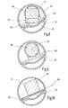
Fig. 1 dargestellt. Dort ist ersichtlich, dass ein Bildsensor 16 mit einem asymmetrischen aktiven Bereich 18 stehend in einem Schaft 10 eingebaut ist. Soll die Bildfläche 20 optimal vom aktiven Bereich 18 erfasst werden, wobei diese Bildfläche meist kreisförmig ist, liegt der Hauptstrahl 21 seitlich versetzt zur Mittellängsachse 14 des Schaftes 10 somit seitlich auch gegenüber dessen Mittelebene 12 versetzt. Damit wäre auch ein asymmetrischer Sichtkegel des Beobachtungsinstrumentes vorhanden. - Ein asymmetrischer Sichtkegel 22 wie er bspw. in
Fig. 3 dargestellt ist, hat aber gewisse Nachteile. InFig. 3 ist ein Schaft 10 eines Endoskopes dargestellt, über den ein Überschaft 24 geschoben ist. Vom distalen Ende des Überschaftes 24 stehen zwei stangenförmige Elemente 26 und 28 vor, die am distalen Ende über eine Resektoskopschlinge 30 verbunden sind. Bei einem asymmetrischen Sichtkegel 22 sieht die Beobachtungsperson aufgrund der Asymmetrie des Sichtkegels 22 zwei axial zueinander versetzte Stellen 27 und 29 der Stangen 26 und 28. Das ist unerwünscht, denn die Beobachtungsperson sieht dann die Stellen bzw., wenn der Schaft 10 weiter nach distal verschoben ist, die Resektoskopschlinge 30 nicht gleichzeitig oder gleichmäßig bzw. auf einer Seite unscharf. Daher sind symmetrische Sichtkegel 22 erwünscht, wie das inFig. 4 dargestellt ist. Dabei liegen dann die Sichtstellen 27' und 29' auf derselben axialen Höhe. - Das kann aber zur Folge haben, wie das in
Fig. 2 dargestellt ist, dass bei einer symmetrisch ausgebildeten Abbildungsoptik die Bildfläche 20 nicht mehr vollumfänglich im aktiven Bereich 18 des asymmetrischen Bildsensors 16 liegt. - Es ist daher Aufgabe der vorliegenden Erfindung hier Abhilfe zu schaffen und ein Beobachtungsinstrument zu schaffen, bei dem bei asymmetrischen Bildsensoren ein möglichst symmetrischer Sichtkegel möglich ist und das Bild möglichst vollständig im aktiven Bereich des Bildsensors liegt.
- Erfindungsgemäß wird die Aufgabe dadurch gelöst, dass eine erste Ebene, die durch den Hauptstrahl und eine erste Orthogonale auf der Bildebene des Bildsensors aufgespannt ist und eine zweite Ebene, die durch den Hauptstrahl und eine zweite Orthogonale auf den Umlenkflächen des distalen Umlenkprismas aufgespannt ist, derart um den Hauptstrahl zueinander verdreht sind, dass ein zur Mittelebene des Hohlschafts symmetrischer Sichtkegel erzeugbar ist, dessen Bildfläche voll im aktiven Bereich des Bildsensors liegt.
- Die Verdrehung dieser beiden Ebenen zueinander um den Hauptstrahl führt dazu, dass der aktive Bereich des asymmetrischen Bildsensors durch diese Drehung in eine Position bringbar ist, in der ein zur Mittelebene des Hohlschafts symmetrischer Sichtkegel ein Bild in den aktiven Bereich abbildet. Durch das Wechselspiel der Ebenen, die einerseits durch die Konstruktion des distalen Umlenkprismas und andererseits durch die Asymmetrie des Bildsensors bestimmt sind, und deren Verdrehung erlaubt es nunmehr den zur Mittelebene symmetrischen Sichtkegel zu erlauben, so dass die eingangs genannten Probleme, wie sie in Zusammenhang mit der Resektoskopschlinge bestehen, nicht mehr auftreten können. Andererseits erfolgt durch eine entsprechende Relativverdrehung eine solche Stellung zwischen den Ebenen, dass dieser symmetrische Sichtkegel auf den bezüglich der Außenkontur des Bildsensors asymmetrischen aktiven Bereich abbildet.
- In einer weiteren Ausgestaltung der Erfindung ist der Bildsensor stehend im Hohlschaft angeordnet.
- Diese Maßnahme hat den Vorteil, dass bei der Montage der stehend angeordnete Bildsensor soweit um die Mittellängsachse des Schaftes verdreht werden kann, bis das von dem distalen Umlenkprisma kommende Bild voll im aktiven Bereich des Bildsensors liegt. Dadurch kann ein hochaufgelöstes Bild unter optimaler Ausnutzung der Auflösung des aktiven Bereiches des Bildsensors erzeugt werden, das einen symmetrischen Sichtkegel erlaubt.
- In einer weiteren Ausgestaltung der Erfindung ist der Bildsensor gegenüber der Längsachse des Schaftes gekippt angeordnet und zwischen dem proximalen Ende des Linsensystems und dem Bildsensor ist ein proximales Umlenkprisma angeordnet, das das vom optischen Linsensystem austretende Bild auf den gekippten Bildsensor umlenkt.
- Diese an sich bekannte Maßnahme hat den Vorteil, dass auch in relativ dünne Schäfte solche Bildsensoren eingebaut werden können.
- In einer weiteren Ausgestaltung der Erfindung ist der Bildsensor liegend und parallel zur Längsachse angeordnet und das proximale Umlenkprisma bewirkt eine 90'-Umlenkung des Bildes.
- Diese Maßnahme hat den Vorteil, dass auch in extrem dünne Schäfte, sich länglich erstreckende rechteckige Bildsensoren eingebaut werden können.
- In einer weiteren Ausgestaltung der Erfindung sind die erste und die zweite Ebene derart zueinander verdreht, dass der Sichtkegel symmetrisch zur Schaftachse verläuft.
- Diese Maßnahme hat den Vorteil, dass trotz der Verdrehung der Ebenen zueinander, ein zur Mittellängs- bzw. Schaftachse symmetrischer Sichtkegel erzeugt wird. Ein solcher Sichtkegel mit dieser hohen Symmetrie erlaubt einen Rundumblick der in allen Objektebenen ein gleich scharfes Bild ergibt.
- In einer weiteren Ausgestaltung der Erfindung ist der Bildsensor mit einer Bildverarbeitungseinheit verbunden, die das durch die Verdrehung verdrehte und ggf. verschobene Bild wieder seiten- und höhenrichtig aufrichtet.
- Durch die Verdrehung der beiden Ebenen zueinander wird das Bild um den entsprechenden Betrag verdreht auf den Bildsensor abgebildet. Je nachdem, wie das erste Umlenkprisma ausgestaltet ist und wie der aktive Bereich im Bildsensor liegt, kann auch das Bild entsprechend verschoben sein.
- Da in der modernen Operationstechnik das Bild meist auf einem Monitor dargestellt wird, ist es für den Operateur zielführend, wenn er das Bild so sieht wie es im Objektfeld vorliegt. Das erleichtert erheblich die Handhabung des Beobachtungsinstrumentes durch den Operateur.
- In einer weiteren Ausgestaltung der Erfindung ist das opto-elektronische Bildaufnehmersystem derart aufgebaut, dass eine von der 0°-Blickrichtung abweichende Blickrichtung erfolgt.
- Diese Maßnahme hat den Vorteil, dass insbesondere bei von der 0°-Richtung abweichenden Blickrichtungen ein hochaufgelöstes Bild erzeugt werden kann. Das distale Umlenkprisma ist dazu vorgesehen, das von der 0°-Blickrichtung abweichende eintretende Bild so umzulenken, dass es möglichst zentral auf das meist stabförmige optische Linsensystem abgebildet wird. Somit können auch bei relativ großen Abweichungen aus der 0°-Richtung, also bspw. 30°, 45° oder 60° und gleichzeitig Verwendung von asymmetrischen Bildsensoren, sehr scharfe und hochauflösende Bilder erzeugt werden.
- Es versteht sich, dass die vorstehend genannten und die nachstehend noch zu erläuternden Merkmale nicht nur in den angegebenen Kombination, sondern auch in anderen Kombinationen einsetzbar sind, ohne den Rahmen der vorliegenden Erfindung zu verlassen.
- Die Erfindung wird anhand einiger ausgewählter Ausführungsbeispiele in Zusammenhang mit den beiliegenden Zeichnungen näher beschrieben und erläutert. Es zeigen:
- Fig. 1
- stark schematisiert einen stehenden Einbau eines asymmetrischen Bildsensors in einen Schaft, wobei die Bildfläche asymmetrisch zur Mittelebene und zur Längsachse ist;
- Fig. 2
- eine Darstellung, bei der bei derselben Bauweise die Bildfläche zwar symmetrisch zur Mittelebene und Längsachse des Schaftes verläuft, aber nicht mehr voll den aktiven Bereich des Bildsensors trifft;
- Fig. 3
- stark schematisch einen Schaft eines Endoskopes mit asymmetrischem Sichtkegel über den ein Überschaft mit einer Resektoskopschlinge geschoben ist;
- Fig. 4
- eine der
Fig. 3 entsprechenden Ansicht mit symmetrischem Sichtkegel; - Fig. 5
- einen Querschnitt durch einen Schaft eines ersten Ausführungsbeispiels eines erfindungsgemäßen Beobachtungsinstruments mit stehend eingebautem Bildsensor;
- Fig. 6
- einen Längsschnitt eines zweiten Ausführungsbeispiels eines erfindungsgemäßen Beobachtungsinstruments in dessen distalem Endbereich;
- Fig. 7
- die Lage der Bilder einmal im Objektfeld, einmal in der Bildebene des Bildsensors entsprechend verdreht und auf dem Monitor wieder aufgerichtet;
- Fig. 8
- ein Schnitt längs der Linie VIII-VIII in
Fig. 6 ; - Fig. 9
- ein Schnitt längs der Linie IX-IX in
Fig. 6 ; - Fig. 10
- einen Schnitt längs der Linie X-X in
Fig. 6 ; - Fig. 11
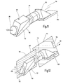
- eine perspektivische Darstellung des zusammengesetzten optoelektronischen Bildaufnehmersystemes, und
- Fig. 12
- eine der
Fig. 11 entsprechende Darstellung, wobei die erste und die zweite Ebene dargestellt sind, sowie deren Maß der Verdrehung zueinander. - Anhand des in
Fig. 5 dargestellten ersten Ausführungsbeispieles eines erfindungsgemäßen Beobachtungsinstrumentes 40 sollen die Grundprinzipien der Erfindung erläutert werden. Das Beobachtungssystem 40 weist einen Schaft 42 auf, in dem stehend ein Bildsensor 44 mit rechteckförmiger Kontur eingebaut ist. - Der Bildsensor 44 weist einen aktiven Bereich 46 auf, der asymmetrisch zu der Außenkontur des Bildsensors 44 angeordnet ist. Die Schaftachse 58 liegt exakt in der Mitte des Schaftes 42. Der Hauptstrahl 52 ist gegenüber der Schaftachse 58 in Richtung der Mittelebene 56 in der Darstellung von
Fig. 5 etwas nach oben verschoben. Die erste Ebene wird durch den Hauptstrahl 52 und die Orthogonale 50 aufgespannt. Die zweite Ebene wird durch die zweite Orthogonale 56, die auf dem Hauptstrahl 52 steht, aufgespannt. Der aktive Bereich 46 des Bildsensors 44 ist um ein solches Maß entgegen dem Uhrzeigersinn gegenüber der Schaftachse 58 verdreht, dass die Bildfläche 60 im aktiven Bereich 46 des Bildsensors 44 liegt. Vergleicht man nun die inFig. 2 dargestellte Lage des Bildsensors mit der inFig. 5 dargestellten Lage, so ist zu erkennen, dass durch das Verdrehen des Bildsensors 44 die Bildfläche 60 voll im aktiven Bereich 46 liegt. Das distale Umlenkprisma (hier nicht ersichtlich) erzeugt im Linsensystem eine Bildfläche 60, die längs der Mittelebene 56 nach oben verschoben ist, jedoch symmetrisch dazu ist. Es ist möglich einen symmetrischen Sichtkegel, wie inFig. 4 dargestellt ist, zu erzeugen und ein hochaufgelöstes Bild vollmittig im aktiven Bereich 46 des Bildsensors 44 zu erhalten, allerdings etwas verdreht und nach "oben" versetzt. - Bei einem in den
Figuren 6 bis 12 dargestellten zweiten Ausführungsbeispiel ist ein Beobachtungsinstrument 70 dargestellt, das einen Schaft 72 aufweist. - Im distalen Endbereich 73 des Schaftes 72 ist ein opto-elektronisches Bildaufnehmersystem 74 aufgenommen.
- Der Innenraum des Schaftes 72 ist durch einen Quersteg 76 in einen ersten Raum 78 und in einen zweiten Raum 80 aufgeteilt.
- Im zweiten Raum 80 ist das Beleuchtungssystem aufgenommen meist Lichtleiter, die distalseitig aus dem zweiten Raum 80 Beleuchtungslicht 82 abgeben.
- Der erste Raum 78 ist distalseitig durch ein Deckglas 84 abgeschlossen. An dieses Deckglas 84 schließt sich eine Linse 86 an, die als eine Fokussierlinse ausgebildet ist. An deren proximales Ende ist eine auf einer gegenüber der Längsachse 94 des Schaftes 72 geneigte Eintrittsfläche eines distalen Umlenkprismas 88 angebracht. Das distale Umlenkprisma 88 weist eine erste Umlenkfläche 90 und eine zweite Umlenkfläche 92 auf. Diese werden auch als Spiegelflächen bezeichnet. Dadurch wird ein Hauptstrahl 112 eines Bildes eines Objektfeldes 107 zentral mittig längs der Längsachse 94 in ein etwa stabförmiges Linsensystem 96 geführt. Am proximalen Ende des Linsensystems 96 ist ein proximales 90°-Umlenkprisma 98 angeordnet, dessen Austrittsfläche auf einem Bildsensor 100 ruht. Der Bildsensor 100 ist somit liegend eingebaut, so dass sich dessen aktiver Bereich 102 bzw. dessen Bildebene 103 parallel und etwas im Abstand zur Mittellängsachse 94 bzw. zum Hauptstrahl 112 erstreckt. Wie zuvor beschrieben ist der aktive Bereich 102 asymmetrisch zur Außenkontur des etwa rechteckförmigen Bildsensors 100 angeordnet.
- In
Fig. 6 ist noch zu erkennen, dass die in dem zweiten Raum 80 aufgenommenen Lichtleiter über eine Leitung 106 mit einer Lichtquelle 104 verbunden sind. Diese ist wiederum mit einer Bildverarbeitungseinheit 108 verbunden, die einerseits mit dem Bildsensor 100 und andererseits mit einem Monitor 110 verbunden ist. Die Lichtquelle 104 kann auch separat stehen. - In
Fig. 6 ist der Verlauf eines Hauptstrahles 112 aufgezeichnet, der von einem Beobachtungsfeld 107 ausgeht, wie es inFig. 7 auf der linken Seite dargestellt ist. Hier soll der große Buchstabe "F" beobachtet werden. Es ist ausFig. 6 zu erkennen, dass die Blickrichtung etwa um 20° aus der 0°-Blickrichtung abweicht, die längs der Längsachse 94 verläuft. - Der Hauptstrahl 112 durchläuft das Deckglas 84 und die Fokussierlinse 86 und wird an der ersten Umlenkfläche 90 auf die zweite Umlenkfläche 92 des distalen Umlenkprismas 88 umgelenkt. Von der zweiten Umlenkfläche 92 wird der Hauptstrahl 112, mittig und in Richtung der Längsachse 94 verlaufend, durch das Linsensystem 96 geführt. Am proximalen Ende des Linsensystems 96 tritt der Hauptstrahl 112 in das proximale Umlenkprisma 98 ein, wird um 90° abgelenkt und trifft auf den aktiven Bereich 102 bzw. die Bildebene 103 des Bildsensors 100.
- Durch die zuvor beschriebene Verdrehung entsteht ein Bild auf dem Bildsensor 100, wie es in
Fig. 7 in der Mitte dargestellt ist, d.h., das "F" ist einmal seitenverkehrt gespiegelt und gedreht. In der Bildverarbeitungseinheit 108 wird das Bild dann entsprechend bearbeitet, so dass auf einem Monitor 110 ein Bild erscheint, wie es inFig. 7 auf der rechten Seite dargestellt ist, also dem ursprünglichen Bild entspricht. - Aus den Schnittdarstellungen von
Fig. 8, 9 und 10 sind die jeweiligen aus Glasmaterial dargestellten optischen Elemente ersichtlich, also das distale Umlenkprisma 88 mit seiner ersten bzw. zweiten Umlenkfläche 90 bzw. 92. InFig. 9 ist das Linsensystem 96 mit dem Hauptstrahl 112 ersichtlich. AusFig. 10 ist ersichtlich, dass das proximale Umlenkprisma 98 den aktiven Bereich 102 des Bildsensors 100 bedeckt, wobei die Bildebene 103 unmittelbar unter der Auflagefläche des proximalen Umlenkprismas 98 liegt. - In
Fig. 11 sind diese Bauelemente noch einmal zusammenhängend perspektivisch dargestellt. InFig. 12 sind nun zusätzlich die beiden Ebenen dargestellt und wie sie zueinander verdreht sind. - Die erste Ebene 114 wird durch den Hauptstrahl 112 und einer auf der Bildebene 103 stehenden Orthogonalen 116 aufgespannt.
- Die zweite Ebene 118 wird ebenfalls durch den Hauptstrahl 112 und einer zweiten Orthogonalen 120 aufgespannt, die auf den Umlenkflächen 90, 92 des distalen Umlenkprismas 88 steht.
- Die erste Ebene 114 ist gegenüber der zweiten Ebene 118 nunmehr so verdreht, dass, wenn man auf den Bildsensor 100 blickt, eine Situation eintritt, wie sie in
Fig. 5 dargestellt ist. Ein Unterschied zwischen der Darstellung vonFig. 12 undFig. 5 besteht darin, dass inFig. 12 der Bildsensor 100 liegend und nicht, wie inFig. 5 , stehend angeordnet ist. Das Grundprinzip ist aber bei beiden Ausgestaltungen gleich. - Es ist bei der zweiten Ausführung möglich die erste und die zweite Ebene 114 bzw. 118 so zueinander zu verdrehen bzw. die Umlenkflächen 90 und 92 des distalen Umlenkprismas 88 so anzuordnen, dass ein symmetrischer Sichtkegel 22 erzeugt wird, wie er in
Fig. 4 dargestellt ist.
Claims (7)
- Beobachtungsinstrument, mit einem, eine Mittelebene (12, 56) aufweisenden Hohlschaft (10, 42, 72) in dessem distalen Endbereich (73) ein opto-elektronisches Bildaufnehmersystem (74) angeordnet ist, das bildeintrittseitig ein distales Umlenkprisma (88) aufweist, dessen Umlenkflächen (90, 92) ein Bild in ein optisches Linsensystem (96) leiten, das das Bild auf einen proximal vom Linsensystem (96) angeordneten Bildsensor (16, 100) auf dessen Bildebene (103) abbildet, wobei der Bildsensor (16, 100) einen aktiven Bereich (18, 102) aufweist, der asymmetrisch zur Außenkontur des Bildsensors (16, 100) liegt, wobei eine erste Ebene (114), die durch den Hauptstrahl (21, 52, 112) und eine erste Orthogonale (50, 116) auf der Bildebene (103) des Bildsensors (16, 100) aufgespannt ist, und eine zweite Ebene (118), die durch den Hauptstrahl (21, 52, 112) und eine zweite Orthogonale auf den Umlenkflächen (90, 92) des distalen Umlenkprismas (88) aufgespannt ist, derart um den Hauptstrahl (21, 52, 112) zueinander verdreht sind, dass ein zu einer Mittelebene (12) des Hohlschafts (10, 72) symmetrischer Sichtkegel (22) erzeugbar ist, dessen Bildfläche (60) voll im aktiven Bereich (18, 102) des Bildsensors (16, 100) liegt.
- Beobachtungsinstrument nach Anspruch 1, dadurch gekennzeichnet, dass der Bildsensor (44) stehend im Hohlschaft (12) angeordnet ist.
- Beobachtungsinstrument nach Anspruch 1, dadurch gekennzeichnet, dass der Bildsensor (100) gegenüber der Längsachse (94) des Schaftes gekippt angeordnet ist und zwischen dem proximalen Ende des Linsensystems (96) und dem Bildsensor (100), ein proximales Umlenkprisma (98) angeordnet ist, das das vom optischen Linsensystem (96) austretende Bild auf den gekippten Bildsensor (100) umlenkt.
- Beobachtungsinstrument nach Anspruch 3, dadurch gekennzeichnet, dass der Bildsensor (100) liegend und parallel zur Längsachse (94) angeordnet ist, und dass das proximale Umlenkprisma (98) eine 90°-Umlenkung des Bildes bewirkt.
- Beobachtungsinstrument nach einem der Ansprüche 1 bis 4, dadurch gekennzeichnet, dass die erste und die zweite Ebene (114, 118) derart zueinander verdreht sind, dass der Sichtkegel (22) symmetrisch zur Schaftachse (12, 94) verläuft.
- Beobachtungsinstrument nach einem der Ansprüche 1 bis 5, dadurch gekennzeichnet, dass der Bildsensor (100) mit einer Bildverarbeitungseinheit (108) verbunden ist, die das durch die Verdrehung verdrehte und ggf. verschobene Bild wieder seiten- und höhenrichtig aufrichtet.
- Beobachtungsinstrument nach einem der Ansprüche 1 bis 6, dadurch gekennzeichnet, dass das opto-elektronische Bildaufnehmersystem (74) derart aufgebaut ist, dass eine von der 0°-Blickrichtung abweichende Blickrichtung erfolgt.
Applications Claiming Priority (1)
| Application Number | Priority Date | Filing Date | Title |
|---|---|---|---|
| DE102013106278.4A DE102013106278A1 (de) | 2013-06-17 | 2013-06-17 | Beobachtungsinstrument mit einem symmetrischen Bildfeld unter Verwendung asymmetrischer Bildsensoren |
Publications (2)
| Publication Number | Publication Date |
|---|---|
| EP2818094A1 true EP2818094A1 (de) | 2014-12-31 |
| EP2818094B1 EP2818094B1 (de) | 2020-07-29 |
Family
ID=50972509
Family Applications (1)
| Application Number | Title | Priority Date | Filing Date |
|---|---|---|---|
| EP14172499.7A Active EP2818094B1 (de) | 2013-06-17 | 2014-06-16 | Beobachtungsinstrument mit einem symmetrischen bildfeld unter verwendung asymmetrischer bildsensoren |
Country Status (3)
| Country | Link |
|---|---|
| US (1) | US9532010B2 (de) |
| EP (1) | EP2818094B1 (de) |
| DE (1) | DE102013106278A1 (de) |
Families Citing this family (4)
| Publication number | Priority date | Publication date | Assignee | Title |
|---|---|---|---|---|
| JP6064089B1 (ja) * | 2015-03-05 | 2017-01-18 | オリンパス株式会社 | 内視鏡 |
| DE102015121017B4 (de) * | 2015-12-03 | 2025-12-04 | Karl Storz Se & Co. Kg | Medizinische Beobachtungsvorrichtung mit einer Bedieneinheit sowie Verwendung eines Eingabemoduls |
| US11066562B2 (en) * | 2017-01-31 | 2021-07-20 | Hewlett-Packard Development Company, L.P. | Acrylamide-containing photo active co-solvents |
| DE102020100674A1 (de) * | 2020-01-14 | 2021-07-15 | Karl Storz Se & Co. Kg | Optisches Beobachtungsinstrument sowie Verfahren zum Erzeugen eines Stereobilds eines Objektfelds |
Citations (7)
| Publication number | Priority date | Publication date | Assignee | Title |
|---|---|---|---|---|
| US4720178A (en) | 1984-08-15 | 1988-01-19 | Olympus Optical Co., Ltd. | Optical system for endoscope |
| DE3736688A1 (de) * | 1986-12-08 | 1988-06-16 | Olympus Optical Co | Bilderzeugungsvorrichtung |
| US4809680A (en) | 1986-09-01 | 1989-03-07 | Olympus Optical Co., Ltd. | Endoscope tip |
| US4918521A (en) * | 1987-01-20 | 1990-04-17 | Olympus Optical Co., Ltd. | Solid state imaging apparatus |
| JPH09122071A (ja) * | 1995-10-30 | 1997-05-13 | Fuji Photo Optical Co Ltd | 斜視型電子内視鏡 |
| US20080091064A1 (en) * | 2006-10-17 | 2008-04-17 | Vadim Laser | Portable endoscope for intubation |
| EP2719321A1 (de) * | 2012-04-25 | 2014-04-16 | Olympus Medical Systems Corp. | Bildaufnahmeeinheit für ein endoskop und endoskop |
Family Cites Families (7)
| Publication number | Priority date | Publication date | Assignee | Title |
|---|---|---|---|---|
| GB778276A (en) * | 1954-10-21 | 1957-07-03 | Richard Wolf | Improvements in or relating to endoscopes |
| JPS4932490A (de) * | 1972-07-24 | 1974-03-25 | ||
| JPH0673517B2 (ja) * | 1988-02-04 | 1994-09-21 | オリンパス光学工業株式会社 | 電子内視鏡システム |
| JPH1090603A (ja) * | 1996-09-18 | 1998-04-10 | Olympus Optical Co Ltd | 内視鏡光学系 |
| US20070197875A1 (en) * | 2003-11-14 | 2007-08-23 | Osaka Shoji | Endoscope device and imaging method using the same |
| US7458685B2 (en) * | 2005-08-03 | 2008-12-02 | Carestream Health, Inc. | Automated fundus imaging system |
| DE102010022430A1 (de) * | 2010-06-01 | 2011-12-01 | Karl Storz Gmbh & Co. Kg | Sichtfeldvorrichtung für ein Endoskop |
-
2013
- 2013-06-17 DE DE102013106278.4A patent/DE102013106278A1/de active Pending
-
2014
- 2014-06-16 EP EP14172499.7A patent/EP2818094B1/de active Active
- 2014-06-17 US US14/307,045 patent/US9532010B2/en active Active
Patent Citations (7)
| Publication number | Priority date | Publication date | Assignee | Title |
|---|---|---|---|---|
| US4720178A (en) | 1984-08-15 | 1988-01-19 | Olympus Optical Co., Ltd. | Optical system for endoscope |
| US4809680A (en) | 1986-09-01 | 1989-03-07 | Olympus Optical Co., Ltd. | Endoscope tip |
| DE3736688A1 (de) * | 1986-12-08 | 1988-06-16 | Olympus Optical Co | Bilderzeugungsvorrichtung |
| US4918521A (en) * | 1987-01-20 | 1990-04-17 | Olympus Optical Co., Ltd. | Solid state imaging apparatus |
| JPH09122071A (ja) * | 1995-10-30 | 1997-05-13 | Fuji Photo Optical Co Ltd | 斜視型電子内視鏡 |
| US20080091064A1 (en) * | 2006-10-17 | 2008-04-17 | Vadim Laser | Portable endoscope for intubation |
| EP2719321A1 (de) * | 2012-04-25 | 2014-04-16 | Olympus Medical Systems Corp. | Bildaufnahmeeinheit für ein endoskop und endoskop |
Also Published As
| Publication number | Publication date |
|---|---|
| EP2818094B1 (de) | 2020-07-29 |
| DE102013106278A1 (de) | 2014-12-18 |
| US20140368647A1 (en) | 2014-12-18 |
| US9532010B2 (en) | 2016-12-27 |
Similar Documents
| Publication | Publication Date | Title |
|---|---|---|
| EP3276390B1 (de) | Optisches system und chirurgisches instrument mit einem solchen optischen system | |
| DE102008024789A1 (de) | Stereo-Endoskop | |
| EP3367155B1 (de) | Vorrichtung zur erfassung eines stereobilds | |
| DE102010022430A1 (de) | Sichtfeldvorrichtung für ein Endoskop | |
| EP2416200B1 (de) | Endoskop mit einstellbarer Blickrichtung | |
| EP2198767A2 (de) | Endoskop mit einem Endoskopschaft, in dem an seinem distalen Ende eine Abbildungsoptik angeordnet ist | |
| EP2818094B1 (de) | Beobachtungsinstrument mit einem symmetrischen bildfeld unter verwendung asymmetrischer bildsensoren | |
| WO2019072615A1 (de) | Stereoendoskop | |
| DE102014206513A1 (de) | Stereoskopisches Endoskopsystem und Endoskop, Montageverfahren | |
| DE2458306C3 (de) | Optisches System mit schräg nach vorn gerichtetem Sichtfeld | |
| EP3697282B1 (de) | Umlenkprismenbaugruppe für ein endoskop und endoskop mit seitlicher blickrichtung | |
| DE102017123896A1 (de) | Optisches System für ein Stereo-Videoendoskop | |
| EP4127810B1 (de) | Optische anordnung für ein schiefeebenenmikroskop zur verbesserung der auflösung | |
| EP3254148A2 (de) | Endoskop | |
| DE102014107586A1 (de) | 3D-Video-Endoskop | |
| DE102014107456A1 (de) | Endoskop und Lichtübertragungseinrichtung zum Übertragen von Beobachtungslicht für ein Endoskop | |
| WO2012168423A1 (de) | Strahlkombinierer zum kombinieren von zwei jeweils eigenständig gescannten beleuchtungsstrahlen eines lichtrastermikroskops | |
| DE20205080U1 (de) | Immersionsobjektiv und Abschirmelement | |
| DE102008038619B3 (de) | Endoskopobjektiv | |
| EP3168671B1 (de) | Beleuchtungsanordnung | |
| EP3011393B1 (de) | Scaneinrichtung | |
| DE102015100695B4 (de) | Optische Anordnung für ein Laser-Scanner-System | |
| DE102014108596B3 (de) | Objektiv und optisches Gerät | |
| DE102017117374A1 (de) | Prismenanordnung für ein Stereo-Videoendoskop | |
| DE102005005568B4 (de) | Tubus für eine Beobachtungseinrichtung sowie Beobachtungseinrichtung |
Legal Events
| Date | Code | Title | Description |
|---|---|---|---|
| PUAI | Public reference made under article 153(3) epc to a published international application that has entered the european phase |
Free format text: ORIGINAL CODE: 0009012 |
|
| 17P | Request for examination filed |
Effective date: 20140616 |
|
| AK | Designated contracting states |
Kind code of ref document: A1 Designated state(s): AL AT BE BG CH CY CZ DE DK EE ES FI FR GB GR HR HU IE IS IT LI LT LU LV MC MK MT NL NO PL PT RO RS SE SI SK SM TR |
|
| AX | Request for extension of the european patent |
Extension state: BA ME |
|
| R17P | Request for examination filed (corrected) |
Effective date: 20150226 |
|
| RBV | Designated contracting states (corrected) |
Designated state(s): AL AT BE BG CH CY CZ DE DK EE ES FI FR GB GR HR HU IE IS IT LI LT LU LV MC MK MT NL NO PL PT RO RS SE SI SK SM TR |
|
| STAA | Information on the status of an ep patent application or granted ep patent |
Free format text: STATUS: EXAMINATION IS IN PROGRESS |
|
| 17Q | First examination report despatched |
Effective date: 20170315 |
|
| RAP1 | Party data changed (applicant data changed or rights of an application transferred) |
Owner name: KARL STORZ SE & CO. KG |
|
| GRAP | Despatch of communication of intention to grant a patent |
Free format text: ORIGINAL CODE: EPIDOSNIGR1 |
|
| STAA | Information on the status of an ep patent application or granted ep patent |
Free format text: STATUS: GRANT OF PATENT IS INTENDED |
|
| INTG | Intention to grant announced |
Effective date: 20200124 |
|
| RIN1 | Information on inventor provided before grant (corrected) |
Inventor name: SCHWARZ, PETER Inventor name: BAUMANN, HARALD |
|
| GRAS | Grant fee paid |
Free format text: ORIGINAL CODE: EPIDOSNIGR3 |
|
| GRAA | (expected) grant |
Free format text: ORIGINAL CODE: 0009210 |
|
| STAA | Information on the status of an ep patent application or granted ep patent |
Free format text: STATUS: THE PATENT HAS BEEN GRANTED |
|
| AK | Designated contracting states |
Kind code of ref document: B1 Designated state(s): AL AT BE BG CH CY CZ DE DK EE ES FI FR GB GR HR HU IE IS IT LI LT LU LV MC MK MT NL NO PL PT RO RS SE SI SK SM TR |
|
| REG | Reference to a national code |
Ref country code: CH Ref legal event code: EP |
|
| REG | Reference to a national code |
Ref country code: DE Ref legal event code: R096 Ref document number: 502014014513 Country of ref document: DE |
|
| REG | Reference to a national code |
Ref country code: AT Ref legal event code: REF Ref document number: 1294833 Country of ref document: AT Kind code of ref document: T Effective date: 20200815 |
|
| REG | Reference to a national code |
Ref country code: IE Ref legal event code: FG4D Free format text: LANGUAGE OF EP DOCUMENT: GERMAN |
|
| REG | Reference to a national code |
Ref country code: LT Ref legal event code: MG4D |
|
| REG | Reference to a national code |
Ref country code: NL Ref legal event code: MP Effective date: 20200729 |
|
| PG25 | Lapsed in a contracting state [announced via postgrant information from national office to epo] |
Ref country code: ES Free format text: LAPSE BECAUSE OF FAILURE TO SUBMIT A TRANSLATION OF THE DESCRIPTION OR TO PAY THE FEE WITHIN THE PRESCRIBED TIME-LIMIT Effective date: 20200729 Ref country code: NO Free format text: LAPSE BECAUSE OF FAILURE TO SUBMIT A TRANSLATION OF THE DESCRIPTION OR TO PAY THE FEE WITHIN THE PRESCRIBED TIME-LIMIT Effective date: 20201029 Ref country code: BG Free format text: LAPSE BECAUSE OF FAILURE TO SUBMIT A TRANSLATION OF THE DESCRIPTION OR TO PAY THE FEE WITHIN THE PRESCRIBED TIME-LIMIT Effective date: 20201029 Ref country code: LT Free format text: LAPSE BECAUSE OF FAILURE TO SUBMIT A TRANSLATION OF THE DESCRIPTION OR TO PAY THE FEE WITHIN THE PRESCRIBED TIME-LIMIT Effective date: 20200729 Ref country code: HR Free format text: LAPSE BECAUSE OF FAILURE TO SUBMIT A TRANSLATION OF THE DESCRIPTION OR TO PAY THE FEE WITHIN THE PRESCRIBED TIME-LIMIT Effective date: 20200729 Ref country code: GR Free format text: LAPSE BECAUSE OF FAILURE TO SUBMIT A TRANSLATION OF THE DESCRIPTION OR TO PAY THE FEE WITHIN THE PRESCRIBED TIME-LIMIT Effective date: 20201030 Ref country code: FI Free format text: LAPSE BECAUSE OF FAILURE TO SUBMIT A TRANSLATION OF THE DESCRIPTION OR TO PAY THE FEE WITHIN THE PRESCRIBED TIME-LIMIT Effective date: 20200729 Ref country code: PT Free format text: LAPSE BECAUSE OF FAILURE TO SUBMIT A TRANSLATION OF THE DESCRIPTION OR TO PAY THE FEE WITHIN THE PRESCRIBED TIME-LIMIT Effective date: 20201130 Ref country code: SE Free format text: LAPSE BECAUSE OF FAILURE TO SUBMIT A TRANSLATION OF THE DESCRIPTION OR TO PAY THE FEE WITHIN THE PRESCRIBED TIME-LIMIT Effective date: 20200729 |
|
| PG25 | Lapsed in a contracting state [announced via postgrant information from national office to epo] |
Ref country code: LV Free format text: LAPSE BECAUSE OF FAILURE TO SUBMIT A TRANSLATION OF THE DESCRIPTION OR TO PAY THE FEE WITHIN THE PRESCRIBED TIME-LIMIT Effective date: 20200729 Ref country code: RS Free format text: LAPSE BECAUSE OF FAILURE TO SUBMIT A TRANSLATION OF THE DESCRIPTION OR TO PAY THE FEE WITHIN THE PRESCRIBED TIME-LIMIT Effective date: 20200729 Ref country code: PL Free format text: LAPSE BECAUSE OF FAILURE TO SUBMIT A TRANSLATION OF THE DESCRIPTION OR TO PAY THE FEE WITHIN THE PRESCRIBED TIME-LIMIT Effective date: 20200729 Ref country code: IS Free format text: LAPSE BECAUSE OF FAILURE TO SUBMIT A TRANSLATION OF THE DESCRIPTION OR TO PAY THE FEE WITHIN THE PRESCRIBED TIME-LIMIT Effective date: 20201129 |
|
| PG25 | Lapsed in a contracting state [announced via postgrant information from national office to epo] |
Ref country code: NL Free format text: LAPSE BECAUSE OF FAILURE TO SUBMIT A TRANSLATION OF THE DESCRIPTION OR TO PAY THE FEE WITHIN THE PRESCRIBED TIME-LIMIT Effective date: 20200729 |
|
| PG25 | Lapsed in a contracting state [announced via postgrant information from national office to epo] |
Ref country code: EE Free format text: LAPSE BECAUSE OF FAILURE TO SUBMIT A TRANSLATION OF THE DESCRIPTION OR TO PAY THE FEE WITHIN THE PRESCRIBED TIME-LIMIT Effective date: 20200729 Ref country code: CZ Free format text: LAPSE BECAUSE OF FAILURE TO SUBMIT A TRANSLATION OF THE DESCRIPTION OR TO PAY THE FEE WITHIN THE PRESCRIBED TIME-LIMIT Effective date: 20200729 Ref country code: DK Free format text: LAPSE BECAUSE OF FAILURE TO SUBMIT A TRANSLATION OF THE DESCRIPTION OR TO PAY THE FEE WITHIN THE PRESCRIBED TIME-LIMIT Effective date: 20200729 Ref country code: SM Free format text: LAPSE BECAUSE OF FAILURE TO SUBMIT A TRANSLATION OF THE DESCRIPTION OR TO PAY THE FEE WITHIN THE PRESCRIBED TIME-LIMIT Effective date: 20200729 Ref country code: RO Free format text: LAPSE BECAUSE OF FAILURE TO SUBMIT A TRANSLATION OF THE DESCRIPTION OR TO PAY THE FEE WITHIN THE PRESCRIBED TIME-LIMIT Effective date: 20200729 |
|
| REG | Reference to a national code |
Ref country code: DE Ref legal event code: R097 Ref document number: 502014014513 Country of ref document: DE |
|
| PG25 | Lapsed in a contracting state [announced via postgrant information from national office to epo] |
Ref country code: AL Free format text: LAPSE BECAUSE OF FAILURE TO SUBMIT A TRANSLATION OF THE DESCRIPTION OR TO PAY THE FEE WITHIN THE PRESCRIBED TIME-LIMIT Effective date: 20200729 |
|
| PLBE | No opposition filed within time limit |
Free format text: ORIGINAL CODE: 0009261 |
|
| STAA | Information on the status of an ep patent application or granted ep patent |
Free format text: STATUS: NO OPPOSITION FILED WITHIN TIME LIMIT |
|
| PG25 | Lapsed in a contracting state [announced via postgrant information from national office to epo] |
Ref country code: SK Free format text: LAPSE BECAUSE OF FAILURE TO SUBMIT A TRANSLATION OF THE DESCRIPTION OR TO PAY THE FEE WITHIN THE PRESCRIBED TIME-LIMIT Effective date: 20200729 |
|
| 26N | No opposition filed |
Effective date: 20210430 |
|
| PG25 | Lapsed in a contracting state [announced via postgrant information from national office to epo] |
Ref country code: SI Free format text: LAPSE BECAUSE OF FAILURE TO SUBMIT A TRANSLATION OF THE DESCRIPTION OR TO PAY THE FEE WITHIN THE PRESCRIBED TIME-LIMIT Effective date: 20200729 |
|
| PG25 | Lapsed in a contracting state [announced via postgrant information from national office to epo] |
Ref country code: MC Free format text: LAPSE BECAUSE OF FAILURE TO SUBMIT A TRANSLATION OF THE DESCRIPTION OR TO PAY THE FEE WITHIN THE PRESCRIBED TIME-LIMIT Effective date: 20200729 |
|
| REG | Reference to a national code |
Ref country code: CH Ref legal event code: PL |
|
| REG | Reference to a national code |
Ref country code: BE Ref legal event code: MM Effective date: 20210630 |
|
| PG25 | Lapsed in a contracting state [announced via postgrant information from national office to epo] |
Ref country code: LU Free format text: LAPSE BECAUSE OF NON-PAYMENT OF DUE FEES Effective date: 20210616 |
|
| PG25 | Lapsed in a contracting state [announced via postgrant information from national office to epo] |
Ref country code: LI Free format text: LAPSE BECAUSE OF NON-PAYMENT OF DUE FEES Effective date: 20210630 Ref country code: IE Free format text: LAPSE BECAUSE OF NON-PAYMENT OF DUE FEES Effective date: 20210616 Ref country code: CH Free format text: LAPSE BECAUSE OF NON-PAYMENT OF DUE FEES Effective date: 20210630 |
|
| PG25 | Lapsed in a contracting state [announced via postgrant information from national office to epo] |
Ref country code: BE Free format text: LAPSE BECAUSE OF NON-PAYMENT OF DUE FEES Effective date: 20210630 |
|
| REG | Reference to a national code |
Ref country code: AT Ref legal event code: MM01 Ref document number: 1294833 Country of ref document: AT Kind code of ref document: T Effective date: 20210616 |
|
| PG25 | Lapsed in a contracting state [announced via postgrant information from national office to epo] |
Ref country code: AT Free format text: LAPSE BECAUSE OF NON-PAYMENT OF DUE FEES Effective date: 20210616 |
|
| PG25 | Lapsed in a contracting state [announced via postgrant information from national office to epo] |
Ref country code: HU Free format text: LAPSE BECAUSE OF FAILURE TO SUBMIT A TRANSLATION OF THE DESCRIPTION OR TO PAY THE FEE WITHIN THE PRESCRIBED TIME-LIMIT; INVALID AB INITIO Effective date: 20140616 |
|
| PG25 | Lapsed in a contracting state [announced via postgrant information from national office to epo] |
Ref country code: CY Free format text: LAPSE BECAUSE OF FAILURE TO SUBMIT A TRANSLATION OF THE DESCRIPTION OR TO PAY THE FEE WITHIN THE PRESCRIBED TIME-LIMIT Effective date: 20200729 |
|
| P01 | Opt-out of the competence of the unified patent court (upc) registered |
Effective date: 20230527 |
|
| PG25 | Lapsed in a contracting state [announced via postgrant information from national office to epo] |
Ref country code: MK Free format text: LAPSE BECAUSE OF FAILURE TO SUBMIT A TRANSLATION OF THE DESCRIPTION OR TO PAY THE FEE WITHIN THE PRESCRIBED TIME-LIMIT Effective date: 20200729 |
|
| PG25 | Lapsed in a contracting state [announced via postgrant information from national office to epo] |
Ref country code: TR Free format text: LAPSE BECAUSE OF FAILURE TO SUBMIT A TRANSLATION OF THE DESCRIPTION OR TO PAY THE FEE WITHIN THE PRESCRIBED TIME-LIMIT Effective date: 20200729 |
|
| PG25 | Lapsed in a contracting state [announced via postgrant information from national office to epo] |
Ref country code: MT Free format text: LAPSE BECAUSE OF FAILURE TO SUBMIT A TRANSLATION OF THE DESCRIPTION OR TO PAY THE FEE WITHIN THE PRESCRIBED TIME-LIMIT Effective date: 20200729 |
|
| PGFP | Annual fee paid to national office [announced via postgrant information from national office to epo] |
Ref country code: DE Payment date: 20250626 Year of fee payment: 12 |
|
| PGFP | Annual fee paid to national office [announced via postgrant information from national office to epo] |
Ref country code: GB Payment date: 20250617 Year of fee payment: 12 |
|
| PGFP | Annual fee paid to national office [announced via postgrant information from national office to epo] |
Ref country code: FR Payment date: 20250624 Year of fee payment: 12 |
|
| PGFP | Annual fee paid to national office [announced via postgrant information from national office to epo] |
Ref country code: IT Payment date: 20250623 Year of fee payment: 12 |