EP2817561B1 - Explosionsgeschützte leuchte mit eingegossener optik - Google Patents
Explosionsgeschützte leuchte mit eingegossener optik Download PDFInfo
- Publication number
- EP2817561B1 EP2817561B1 EP13706478.8A EP13706478A EP2817561B1 EP 2817561 B1 EP2817561 B1 EP 2817561B1 EP 13706478 A EP13706478 A EP 13706478A EP 2817561 B1 EP2817561 B1 EP 2817561B1
- Authority
- EP
- European Patent Office
- Prior art keywords
- optical element
- explosion
- lighting unit
- light
- proof lighting
- Prior art date
- Legal status (The legal status is an assumption and is not a legal conclusion. Google has not performed a legal analysis and makes no representation as to the accuracy of the status listed.)
- Not-in-force
Links
Images


Classifications
-
- F—MECHANICAL ENGINEERING; LIGHTING; HEATING; WEAPONS; BLASTING
- F21—LIGHTING
- F21V—FUNCTIONAL FEATURES OR DETAILS OF LIGHTING DEVICES OR SYSTEMS THEREOF; STRUCTURAL COMBINATIONS OF LIGHTING DEVICES WITH OTHER ARTICLES, NOT OTHERWISE PROVIDED FOR
- F21V25/00—Safety devices structurally associated with lighting devices
- F21V25/12—Flameproof or explosion-proof arrangements
-
- F—MECHANICAL ENGINEERING; LIGHTING; HEATING; WEAPONS; BLASTING
- F21—LIGHTING
- F21V—FUNCTIONAL FEATURES OR DETAILS OF LIGHTING DEVICES OR SYSTEMS THEREOF; STRUCTURAL COMBINATIONS OF LIGHTING DEVICES WITH OTHER ARTICLES, NOT OTHERWISE PROVIDED FOR
- F21V17/00—Fastening of component parts of lighting devices, e.g. shades, globes, refractors, reflectors, filters, screens, grids or protective cages
- F21V17/10—Fastening of component parts of lighting devices, e.g. shades, globes, refractors, reflectors, filters, screens, grids or protective cages characterised by specific fastening means or way of fastening
-
- F—MECHANICAL ENGINEERING; LIGHTING; HEATING; WEAPONS; BLASTING
- F21—LIGHTING
- F21V—FUNCTIONAL FEATURES OR DETAILS OF LIGHTING DEVICES OR SYSTEMS THEREOF; STRUCTURAL COMBINATIONS OF LIGHTING DEVICES WITH OTHER ARTICLES, NOT OTHERWISE PROVIDED FOR
- F21V31/00—Gas-tight or water-tight arrangements
- F21V31/04—Provision of filling media
-
- F—MECHANICAL ENGINEERING; LIGHTING; HEATING; WEAPONS; BLASTING
- F21—LIGHTING
- F21V—FUNCTIONAL FEATURES OR DETAILS OF LIGHTING DEVICES OR SYSTEMS THEREOF; STRUCTURAL COMBINATIONS OF LIGHTING DEVICES WITH OTHER ARTICLES, NOT OTHERWISE PROVIDED FOR
- F21V5/00—Refractors for light sources
-
- F—MECHANICAL ENGINEERING; LIGHTING; HEATING; WEAPONS; BLASTING
- F21—LIGHTING
- F21V—FUNCTIONAL FEATURES OR DETAILS OF LIGHTING DEVICES OR SYSTEMS THEREOF; STRUCTURAL COMBINATIONS OF LIGHTING DEVICES WITH OTHER ARTICLES, NOT OTHERWISE PROVIDED FOR
- F21V5/00—Refractors for light sources
- F21V5/007—Array of lenses or refractors for a cluster of light sources, e.g. for arrangement of multiple light sources in one plane
-
- F—MECHANICAL ENGINEERING; LIGHTING; HEATING; WEAPONS; BLASTING
- F21—LIGHTING
- F21V—FUNCTIONAL FEATURES OR DETAILS OF LIGHTING DEVICES OR SYSTEMS THEREOF; STRUCTURAL COMBINATIONS OF LIGHTING DEVICES WITH OTHER ARTICLES, NOT OTHERWISE PROVIDED FOR
- F21V7/00—Reflectors for light sources
-
- F—MECHANICAL ENGINEERING; LIGHTING; HEATING; WEAPONS; BLASTING
- F21—LIGHTING
- F21V—FUNCTIONAL FEATURES OR DETAILS OF LIGHTING DEVICES OR SYSTEMS THEREOF; STRUCTURAL COMBINATIONS OF LIGHTING DEVICES WITH OTHER ARTICLES, NOT OTHERWISE PROVIDED FOR
- F21V17/00—Fastening of component parts of lighting devices, e.g. shades, globes, refractors, reflectors, filters, screens, grids or protective cages
- F21V17/10—Fastening of component parts of lighting devices, e.g. shades, globes, refractors, reflectors, filters, screens, grids or protective cages characterised by specific fastening means or way of fastening
- F21V17/101—Fastening of component parts of lighting devices, e.g. shades, globes, refractors, reflectors, filters, screens, grids or protective cages characterised by specific fastening means or way of fastening permanently, e.g. welding, gluing or riveting
-
- F—MECHANICAL ENGINEERING; LIGHTING; HEATING; WEAPONS; BLASTING
- F21—LIGHTING
- F21V—FUNCTIONAL FEATURES OR DETAILS OF LIGHTING DEVICES OR SYSTEMS THEREOF; STRUCTURAL COMBINATIONS OF LIGHTING DEVICES WITH OTHER ARTICLES, NOT OTHERWISE PROVIDED FOR
- F21V7/00—Reflectors for light sources
- F21V7/0091—Reflectors for light sources using total internal reflection
-
- F—MECHANICAL ENGINEERING; LIGHTING; HEATING; WEAPONS; BLASTING
- F21—LIGHTING
- F21Y—INDEXING SCHEME ASSOCIATED WITH SUBCLASSES F21K, F21L, F21S and F21V, RELATING TO THE FORM OR THE KIND OF THE LIGHT SOURCES OR OF THE COLOUR OF THE LIGHT EMITTED
- F21Y2105/00—Planar light sources
- F21Y2105/10—Planar light sources comprising a two-dimensional [2D] array of point-like light-generating elements
-
- F—MECHANICAL ENGINEERING; LIGHTING; HEATING; WEAPONS; BLASTING
- F21—LIGHTING
- F21Y—INDEXING SCHEME ASSOCIATED WITH SUBCLASSES F21K, F21L, F21S and F21V, RELATING TO THE FORM OR THE KIND OF THE LIGHT SOURCES OR OF THE COLOUR OF THE LIGHT EMITTED
- F21Y2115/00—Light-generating elements of semiconductor light sources
- F21Y2115/10—Light-emitting diodes [LED]
Definitions
- the invention relates to an explosion-proof luminaire with at least one light-emitting diode.
- Light-emitting diodes are increasingly being used in luminaires. They can be used as conventional semiconductor components or in so-called SMD design as lighting for the luminaire. Depending on the design, the radiant power or the heat development of such light-emitting diodes may be sufficient to ignite an ignitable gas mixture present in a potentially explosive area. Therefore, protective measures must be taken in order to be able to use a luminaire equipped with LEDs in a potentially explosive area.
- An encapsulated light-emitting diode arrangement for use in potentially explosive areas is, for example DE 10 2009 005 547 A1 known.
- the light-emitting diode is arranged there between a bottom and a hood and completely enclosed in the receiving space formed by the bottom and the hood.
- the leads for electrically contacting the light emitting diode are led out through the bottom.
- the receiving space can be closed in a gastight manner and executed in explosion-proof "flameproof enclosure". For larger lights, however, the effort is very large, pressure-tight to encapsulate each LED with the help of a bottom and a hood.
- the flameproof enclosure of several light emitting diodes of a luminaire for use in a potentially explosive area is no longer necessary DE 100 24 427 A1 known.
- This lamp has a housing which is hermetically sealed to the outside and forms a flameproof enclosure. Inside the housing are several LEDs on a common PCB arranged. The housing encloses a relatively large volume of gas. Due to the large number of light-emitting diodes, it is necessary for the housing to have a very high compressive strength in order to meet the requirements for explosion protection in the degree of protection flameproof enclosure.
- GB 2458345 A describes a luminaire with an optical element which is transparent to the light emitted by a light-emitting diode and has an accommodating space which is open towards its underside.
- the light emitting diode is arranged in the receiving space.
- the light from the light-emitting diode enters the optical element at a beam entry surface adjoining the receiving space and partially at a beam exit surface above a potting body.
- the light emitting diodes of the lamp are arranged on a printed circuit board. On the circuit board walls are arranged, which enclose areas into which a potting compound for producing the potting body can be filled.
- each LED is covered by a lens.
- the light emitting diodes are arranged on a circuit board, which can be arranged in a recess of a housing.
- a filling compound filled in the recess protects the lenses arranged on the light-emitting diodes.
- the explosion-proof lamp at least one and preferably a plurality of light emitting diodes, which are arranged in a trough.
- One or more of the LEDs are arranged on a common carrier, according to the invention a printed circuit board.
- the carrier or the circuit board may form the bottom of the tub. Sidewall elements or even a peripheral frame can be connected to the carrier or circuit board in order to form the trough.
- the printed circuit board has a printed circuit board core, in particular a metal core, which has at least one or two angled edge regions or webs which each form a side wall of the trough.
- the web or webs is or are an integral integral part of the PCB core and go without seam or joint in the bottom portion of the PCB core over.
- An electrical connection line is electrically connected to the two electrical terminals of the at least one light emitting diode.
- the lamp further comprises an optical element which is transparent to the light emitted by the light emitting diode.
- the at least one light-emitting diode is arranged in a receiving space open towards the underside of the optical element. Between the light-emitting diode and the optical element there is a gap which is provided at least in the region in which the light emitted by the light-emitting diode arrives at a beam entry surface in the optical element.
- This gap can be filled with a gas, for example with air or another gaseous and / or liquid and / or gelatinous and / or solid filling medium.
- the refractive index of this filling medium is less than or equal to 1.5 and in particular less than or equal to 1.3 and in particular less than or equal to 1.1.
- the gap can also prevail a vacuum.
- the beam entry surface is at least part of the area bounding the receiving space of the optical Elements formed.
- the at least one light-emitting diode and the optical light are arranged in a trough of the luminaire, wherein the underside of the optical element is assigned to the bottom of the trough.
- the tub can be made of metal, for example, and preferably of aluminum.
- the optical element can be glued with its underside, for example, on the carrier or the circuit board. For this purpose, preferably a self-adhesive film or an adhesive can be used.
- a cast body is made of a pourable material and arranged.
- the material used for the cast body is, for example, resin, such as silicone resin, polyurethane resin or epoxy resin.
- the cast body surrounds only a part of the optical element and combines during curing cohesively with the tub and the optical element.
- the LEDs are hermetically sealed in the tub.
- the receiving space in the optical element for receiving the at least one light-emitting diode remains free of the pourable material of the cast body.
- the receiving space can form a pressure chamber according to the standard in the case of flameproof enclosure and in the case of Vergusskapselung a free cavity.
- a beam exit surface is provided for each light-emitting diode through which the light which has entered the optical element via the beam entry surface emerges again.
- the jet exit surface is at the Part of the optical element provided, which is not enclosed or covered by the casting.
- the cast body adapted to the requirements of the explosion protection material can be selected, which can be selected completely independent of its optical properties. Only at the beam entrance surface, light from the light emitting diode is coupled into the optical element and this coupled-in light is emitted at the beam exit surface. Refraction or reflection at the interface between the optical element and the cast body preferably does not occur.
- the optical element also separates the cast body from the light emitting diodes. Thermal changes in length of the cast body during operation of the lamp can therefore not lead to damage to the electrical connection between the at least one light-emitting diode and the connecting line. In particular, solder joints between a light-emitting diode and a printed circuit board are not damaged by thermal stresses.
- the edge of the potting closes directly to the beam exit surface and encloses them completely, for example. This ensures that the largest possible Part of the optical element is covered by the potting compound of the cast body in order to achieve a sufficient compressive strength. However, the beam exit surface is not covered by the potting body, so that the potting body does not adversely affect the luminous power of the luminaire.
- each light emitting diode may be associated with a separate optical element, each having a receiving space. It is also possible to provide in a single optical element a plurality of separate receiving spaces for each light emitting diode. According to the number of light-emitting diodes, this optical element has a plurality of beam entry surfaces and beam exit surfaces. If a separate receiving space is present for each light-emitting diode, the volume remaining in the receiving space, for example gas or air volume enclosed in the light, can be made very small. This is advantageous for achieving the explosion protection type flameproof enclosure or Vergusskapselung.
- the jet exit surfaces are preferably spaced apart from one another, wherein a part of the cast body can be arranged between two adjacent jet exit surfaces.
- the emission characteristic can be adapted very simply by varying the number of light-emitting diodes and their relative position in the receiving space to specific lighting requirements.
- the adjacent light emitting diodes associated beam exit surfaces may overlap in this case.
- the optical element adjacent to the beam entry surface has a beam guiding surface having.
- the beam guiding surface adjoins a chamber filled with gas or air or another medium in the optical element.
- the chamber may be filled with the same filling medium as the gap in the receiving space. Also in the chamber can prevail a vacuum.
- a portion of the outer light beams of the light coupled into the optical element through the beam entry surface relative to the optical axis of the light emitting diode is completely reflected at the beam guide surface.
- the beam guiding surface is preferably arranged obliquely with respect to the optical axis of the light-emitting diode. At the beam guide occurs total reflection and no refraction.
- the beam guide surface prevents the part of the light which is not directed directly onto the beam exit surface from occurring on the interface between the optical element and the potting body. Through the beam guide surface, this part of the light is deflected by total reflection on the beam exit surface.
- the chamber for example, filled with air, to which the Strahlleit Structure adjacent, and the receiving space of the associated light emitting diode may be interconnected.
- the beam guiding surface may be closed annularly around the optical axis of the light-emitting diode.
- the carrier or the printed circuit board may be arranged a common heat sink.
- the circuit board may be constructed in multiple layers and have a metal core and / or a graphite layer in order to better dissipate the heat of the light-emitting diode or light-emitting diodes arranged thereon.
- the carrier or the printed circuit board is directly in contact with the trough of the luminaire or at least forms part of the luminaire Tub, whereby the tub is used for heat dissipation.
- the beam entry surface associated with a light emitting diode and the beam exit surface of the optical element associated with the same light emitting diode are at a constant distance from each other.
- the two surfaces can each extend in a plane which are arranged parallel to each other. Alternatively, it is also possible that the two surfaces are curved and have the same center of curvature. In particular, the two surfaces can also be arranged concentrically with one another.
- the beam exit surface may be designed as a flat surface in one embodiment of the lamp.
- a Lambertian radiation characteristic can be achieved. It is also possible to set the radiation characteristic of the luminaire in a targeted manner by means of a curvature of the beam exit surface.
- the part of the optical element having the beam exit surface forms a lens, as it were.
- a positive connection can also be produced between the cast body and the tub.
- at least in one of the side walls of the tub on the inside of a projection and / or a recess may be present.
- the pourable material of the cast body flows around the projection or into the recess, so that after hardening of the cast-in material of the cast body, a positive connection between the cast body and the pan is achieved.
- projections and / or recesses may be provided on a plurality of and preferably opposite side walls of the tub.
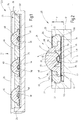
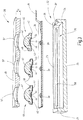
- FIGS. 1 to 3 a first embodiment of an explosion-proof light 20 is illustrated.
- the luminaire 20 has a well 22 which is open towards a radiation side 21.
- the tub 22 is preferably made in one piece without seams and joints of a uniform material.
- the trough is made of a metal, in particular of aluminum.
- the shape and contour of the tub is basically arbitrary.
- the trough 22 in plan view of the emission side 21 has a rectangular shape.
- the trough 22 has two opposite longitudinal side walls 23 and two transverse side walls 24 connecting the two longitudinal side walls 23. On the side opposite the emission side 21, the trough 22 is closed by a bottom 25. The bottom 25 and the four side walls 23, 24 define an interior space 26 for receiving bulbs and possibly other electrical or electronic components.
- the explosion-proof luminaire 20 has at least one and preferably a plurality of light emitting diodes (LEDs) 30 as the light source.
- LEDs light emitting diodes
- the light-emitting diodes 30 are known light-emitting diode types. They have a light-emitting diode chip 31, which is arranged on a chip carrier 32 in the first exemplary embodiment.
- the light-emitting diode chip 31 is covered by a light-emitting diode body 33, which is transparent to the emitted light wavelength, in the emission direction.
- the light emitting diode body 33 has the shape of a hemisphere in the first embodiment.
- the LEDs 30 of the lamp 20 are arranged on a support which is formed by a printed circuit board 34.
- a printed circuit board 34 can also, other electrical or electronic components may be arranged, such as a temperature monitoring device.
- the electrical connections of the LEDs 30 are connected to an electrical connection line 35.
- the LEDs 30 may be connected in parallel or in series with each other with the two wires of the connecting line 35.
- all light emitting diodes 30 of the luminaire 20 are arranged on a single common printed circuit board 34.
- the LEDs 30 are soldered to the top of the circuit board 34. They can be designed as so-called SMD components.
- the light-emitting diodes 30 are arranged along a straight line at a distance from one another on the printed circuit board 34.
- the circuit board 34 may be designed in multiple layers.
- a layer of the printed circuit board 34 may be embodied as a metal and / or a graphite layer, so that the heat in the plane of extension of the printed circuit board 34 is better and more evenly distributed.
- the circuit board 34 is in the embodiment directly on the bottom of the trough 22.
- the light-emitting diodes 30 are arranged completely within the interior 26 of the trough 22.
- the connecting line 25 is led out of the inner space 26 of the trough 22, preferably on one of the transverse side walls 24.
- a section of the side wall inner edge 36 can be provided with a notch or chamfer 37 on the relevant transverse side wall 24, so that the connecting line 35 does not pass through the Side wall inner edge 36 can be kinked or damaged.
- the circuit board 34 forms at least one side wall 23, 24 of the tub, wherein they also the bottom 25 of Can form pan.
- a printed circuit board 34 is illustrated that has a printed circuit board core 34a.
- the printed circuit board core 34a is made of metal, preferably of aluminum. It has a first section 38, which forms the bottom 25 of the trough 22. At the first section 38 close on opposite sides of two angled second sections 39, each forming a side wall and, for example, each a longitudinal side wall 23.
- circuit board 34 could also form the bottom 25 of the tub 22 and be connected to side wall panels or a closed frame to form the tub 22.
- Each light-emitting diode 30 is associated with an optical element 40.
- a separate optical element 40 is provided for each light-emitting diode 30.
- the optical elements 40 each have a receiving space 41 which serves to receive the associated light-emitting diode 30.
- the receiving space 41 is open to a lower side 42 of the optical element 40 and otherwise completely bounded by the optical element 40.
- the bottom 42 is the circuit board 34th assigned.
- the bottom 42 serves to secure the optical element 40 on the circuit board.
- a cohesive connection between the optical element 40 and the printed circuit board 34 around the associated light emitting diode 30 is produced around the circumference.
- an annularly closed adhesive film 34 is used for this purpose, which produces the integral connection between the optical element 40 and the printed circuit board 34.
- This cohesive connection of the receiving space 41 relative to the interior 26 of the tub 22 is sealed.
- the contour of the receiving space 41 is adapted to the outer shape of the light-emitting diode 30.
- the receiving space 41 in the region of the optical axis A of the light-emitting diode 30 therefore has the shape of a hemisphere or spherical cap.
- a spherical cap, concave beam entrance surface 44 of the optical element 40 is formed, which adjoins the receiving space 41.
- a gap 45 is present. The light-emitting diode 30 thus does not abut directly on the beam entry surface 44 of the optical element 40.
- the gap 45 has, for example, a constant thickness, so that the distance of the beam entrance surface 44 from the light-emitting diode 30 or the light-emitting diode body 33 is constant.
- a gaseous and / or liquid and / or gelatinous and / or solid filling medium may be present, for example air.
- a beam exit surface 46 is provided which is provided on the underside 42 opposite top of the optical element 40 and located on the emission side 21 of the lamp 20.
- the beam exit surface 46 preferably has a constant distance to the beam entry surface 44.
- the beam exit surface 46 is designed spherical cap.
- the beam entry surface 44 and the beam exit surface 46 have a common center of curvature and are arranged concentrically to one another.
- the beam exit surface 46 is located outside of the limited by the trough 22 interior 26th
- the beam entry surface 44 and the beam exit surface 46 are arranged on a central region 47 of the optical element 40, which has a hemispherical or spherical cap-shaped outer contour.
- an annular flange 48 is present, which extends along a radial plane through the center of the spherical cap-shaped central region 47.
- the bottom 25 of the tub 22 facing side of the ring flange 48 forms a part of the bottom 42 of the optical element 40th
- the luminaire 20 can be designed in the explosion protection type "flameproof enclosure” (Ex-d) or “encapsulation enclosure” (Ex-m).
- the LEDs 30 and / or optionally present on the circuit board 34 further electrical or electronic components by means of a cast body 49 hermetically sealed against the environment of the lamp 20.
- a thermosetting, pourable material in the interior 26 of the tub 22 is filled around the circuit board 34 and around the lower portion of the optical elements 40 and cured. In this case, the castable material completely surrounds the region of the optical elements 40 which is arranged within the interior 26 of the trough 22.
- the height H of the cast body 49 substantially corresponds to the height of the inner space 26, which is defined by the distance of the upper side of the bottom 25 from the upper edge of the four side walls 23, 24 (FIG. FIG. 2 ) is given.
- the pourable material for the cast body 49 is preferably filled to the upper edge of the side walls 23, 24 in the interior 26 of the tub 22, as in FIG. 1 is illustrated.
- the jet exit surface 46 is arranged according to the example outside of the interior 26 of the trough 22 and therefore remains free and is not covered by the cast body 49.
- the material of the cast body 49 therefore does not necessarily have to be permeable to the light emitted by the light-emitting diode 30.
- a castable material for the cast body 49 a cast resin can be used, such as some silicone resin, polyurethane resin or epoxy resin.
- the cast body 49 combines during curing cohesively with the arranged in the interior 26 of the trough 22 components and adjacent to this interior 26 surfaces, in particular with the trough 22, the lower portions of the optical elements 40 and the circuit board 34. He fills the interior 26 of Trough 22 preferably completely off, so that there remain little or no gas or air pockets.
- the pourable material of the cast body 49 does not penetrate into the receiving space 41 of the optical element 40, since it is firmly bonded to the printed circuit board 34 and firmly against the penetration of the liquid casting compound.
- a projection and / or a depression 50 may be provided on the surface of one or more side walls 23, 24 adjoining the interior 26 of the trough 22.
- a positive connection between the cast body 49 and the trough 22 is additionally achieved.
- Both longitudinal side walls 23 each have a groove-like recess 50 into which the not yet cured potting compound penetrates during filling into the trough 22, so that the cast body 49 there formed in the recesses 50 protruding projections 51. The compressive strength of the luminaire 20 is thereby further improved.
- the height H of the cast body which corresponds, for example, the height H of the interior of the trough 22, must have a minimum height.
- the opening angle of the Lichtabstrahl Anlagens the light-emitting diodes 30 may be very large and, for example, be up to 150 °, so that the marginal rays with the optical axis A of the LED 30 include an angle of 75 °.
- a beam guide surface 55 is present adjacent to the beam entry surface 44.
- the beam guide surface 55 is arranged in a ring-shaped manner around the optical axis A of the light-emitting diode 30 on the optical element 40. It extends obliquely to the optical axis A and has the shape of a lateral surface of a circular truncated cone in the first embodiment of the lamp 20.
- the beam guide surface 55 adjoins an example filled with air chamber 56 of the optical element 40.
- the chamber 56 is connected to the embodiment following the bottom 42 of the optical element 40 with the receiving space 41 for the light emitting diode 30.
- the chamber 56 is open to the bottom 42.
- the chamber is preferably filled with the same filling medium as the gap 45 of the receiving space 41. In the chamber 56 and / or in the receiving space 41 can also be a vacuum.
- the beam guide surface 55 is arranged such that all light rays entering the optical element 40 at the beam entry surface 44, which are not directly directed rectilinearly onto the beam exit surface 46, strike the beam guide surface 55 and are reflected there without refraction and deflected to the beam exit surface 46.
- the optical element 40 and in particular the beam guide surface 55 is preferably uncoated.
- the circular edge 57 formed between the cast body 49 and the optical element 40 in the exemplary embodiment can connect directly to the beam exit surface 46.
- the edge 57 predetermines the maximum size of the beam exit surface 46.
- FIGS. 4 to 7 a second embodiment of a lamp 20 is shown.
- the light-emitting diodes 30 are arranged in the second embodiment in a matrix-like manner in a plurality of rows and columns next to each other in the trough 22.
- Each optical element 40 has a plurality of dome-shaped central sections 47, which are connected to each other via a bottom side 42 of the optical element 40 having plate-shaped portion 60.
- Each optical element 40 is associated with a plurality of light emitting diodes 30 in the second embodiment and has a corresponding number of receiving spaces 41. In the embodiment described here, nine receiving spaces 41 are provided for each one light-emitting diode 30.
- Each light-emitting diode 30 or each receiving space 41 is associated with a dome-shaped central portion 47.
- the beam exit surface 46 is provided on this dome-shaped central portion 47.
- each receiving space 41 has a cuboid shape. This is due to the fact that the light emitting diodes 30 and in particular the diode body in this embodiment has a cuboid outer contour, to which the shape of the receiving space 41 is adapted.
- the beam entrance surface 44 is designed here as a flat surface. As in the first embodiment, there is a gap 45 of constant thickness between the light emitting diode 30 and the beam entrance surface 44. The light rays emitted from the light emitting diode 30 are therefore refracted at the boundary layer of the air in the gap 45 and the material of the optical element 40.
- the light rays entering at the beam entry surface 44 are deflected toward the optical axis A of the light-emitting diode 30.
- the opening angle between the peripheral light beams is therefore reduced after entering the optical element 40.
- the distance and the size the beam exit surface 46 of the beam entry surface 44 is selected so that the light rays propagating straight through the optical element 40 incident exclusively on the beam exit surface and can exit there unhindered.
- the beam exit surface 46 is designed curved here as in the first embodiment. Since the beam entry surface 44 extends in a plane, the distance between the beam entry surface 44 and the beam exit surface 46 is not constant. It is largest along the optical axis A. The beam exit surface 46 and the central portion 47 thereby have a lens effect. It is understood that the curvature of the beam exit surface 46 may have other curvature forms depending on the desired radiation characteristic.
- a cylindrical and, for example circular cylindrical transition portion 61 may be provided which in FIG. 7 indicated by dashed lines.
- the second embodiment corresponds to the lamp according to the FIGS. 4 to 7 the first embodiment described above, so that reference is made to the description of the first embodiment.
- FIGS. 8 to 11 is a further, third embodiment of the lamp 20 illustrated.
- This third embodiment corresponds essentially to the second embodiment, so that reference is made to the above description.
- the difference between the Second and the third embodiment is that the central portions 47 of an optical element 40 have no dome shape, but a cuboid shape. Accordingly, a cuboid central section 47 adjoins the common plate-shaped section 60 of an optical element 40 for each receiving space 41 or for each light-emitting diode 30.
- the beam exit surface 46 is not curved, but flat.
- the beam exit surfaces 46 of an optical element 40 extend in a common plane, which can extend in the plane of the upper edge of the trough 22.
- the optical element 40 protrude from the interior 26 of the tub 22 ( FIGS. 8 and 9 ).
- the height H of the cast body 49 is selected so that it reaches down to the beam exit surfaces 46 and completely fills the interior 26 of the trough 22, but the jet exit surfaces 46 remain free.
- the opening angle of the light rays emerging from the beam exit surface 46 corresponds to the opening angle of the light rays () impinging on the beam entry surface (FIG. FIG. 11 ).
- a fourth embodiment of the luminaire 20 is in the FIGS. 12 to 14 illustrated. In essence, this embodiment corresponds to the third embodiment according to FIG FIGS. 8 to 11 so that reference is made to the above description. Only differences to the third embodiment will be explained below.
- the optical element 40 is associated with a plurality of LEDs 30. It has a plurality of receiving spaces 41 which, as in the third embodiment, have a cuboidal contour. In contrast to the third embodiment, a plurality of LEDs 30 are arranged in a row next to each other in a receiving space 41. In a modification to this, it would also be possible to arrange the light-emitting diodes 30 in a receiving space 41 in a matrix-like manner in rows and columns next to one another or to distribute them irregularly in the receiving space 41. The distances between each two adjacent light-emitting diodes 30 can be chosen the same or different sizes. Each receiving space is assigned a cuboid central section 47.
- an optical element 40 has three parallelepiped central sections 47, each having a plurality of beam exit surfaces 46. Each of these cuboid central sections 47 is associated with a cuboid receiving space 41 adjacent to the bottom 42.
- an optical element 40 may also have only a single receiving space 41 for all light-emitting diodes 30. Combinations and modifications of the various embodiments are possible.
- a luminaire may also have different optical elements 40, as described above.
- the present invention relates to an explosion-proof luminaire 20 with a plurality of light emitting diodes 30.
- a printed circuit board 34 is arranged, on which the light-emitting diodes 30 are electrically and mechanically fixed.
- an optical element 40 is arranged on the printed circuit board 34.
- the light-emitting diode 30 is located in a receiving space 41 of the optical element 40.
- the light emitted by the light-emitting diode 30 enters the optical element 40 at a beam entry surface 44 adjacent to the receiving space 41 and exits at a beam exit surface 46. Between the beam entry surface 44 and the light emitting diode 30, a gap 45 is present.
- the printed circuit board 34 and the light-emitting diodes 30 associated optical elements 40 are cast.
- a cast body 49 fills the interior of the tub 22 around the circuit board, the optical elements and optionally further electrical and electronic components.
- the beam exit surface 46 is not covered by the potting body 49 and may be located outside the interior of the trough 22.
- the luminaire 20 is designed in explosion-proof encapsulation or flameproof enclosure.
Landscapes
- Engineering & Computer Science (AREA)
- General Engineering & Computer Science (AREA)
- Non-Portable Lighting Devices Or Systems Thereof (AREA)
- Led Device Packages (AREA)
- Arrangement Of Elements, Cooling, Sealing, Or The Like Of Lighting Devices (AREA)
- Illuminated Signs And Luminous Advertising (AREA)
Description
- Die Erfindung betrifft eine explosionsgeschützte Leuchte mit wenigstens einer Leuchtdiode. Leuchtdioden werden immer häufiger in Leuchten eingesetzt. Sie können als herkömmliche Halbleiterbauelemente oder in sogenannter SMD-Ausführung als Leuchtmittel für die Leuchte verwendet werden. Die Strahlungsleistung oder die Wärmeentwicklung solcher Leuchtdioden kann abhängig von der Ausführung ausreichen, um ein in einem explosionsgefährdeten Bereich vorhandenes zündfähiges Gasgemisch zu entzünden. Es sind daher Schutzvorkehrungen zu treffen, um eine mit Leuchtdioden ausgestattete Leuchte in einem explosionsgefährdeten Bereich verwenden zu können.
- Eine gekapselte Leuchtdiodenanordnung für die Verwendung in explosionsgefährdeten Bereichen ist beispielsweise aus
DE 10 2009 005 547 A1 bekannt. Die Leuchtdiode ist dort zwischen einem Boden und einer Haube angeordnet und in den durch den Boden und die Haube gebildeten Aufnahmeraum vollständig eingeschlossen. Die Anschlussleitungen zum elektrischen Kontaktieren der Leuchtdiode sind durch den Boden herausgeführt. Der Aufnahmeraum kann gasdicht geschlossen sein und in der Explosionsschutzart "druckfeste Kapselung" ausgeführt sein. Bei größeren Leuchten ist allerdings der Aufwand sehr groß, jede Leuchtdiode mit Hilfe eines Bodens und einer Haube druckfest zu kapseln. - Die druckfeste Kapselung mehrerer Leuchtdioden einer Leuchte für den Einsatz in einem explosionsgefährdeten Bereichen ist aus
DE 100 24 427 A1 bekannt. Diese Leuchte weist ein Gehäuse auf, das nach außen hermetisch geschlossen ist und eine druckfeste Kapselung bildet. Im Inneren des Gehäuses sind mehrere Leuchtdioden auf einer gemeinsamen Leiterplatte angeordnet. Das Gehäuse umschließt ein relativ großes Gasvolumen. Durch die Vielzahl der Leuchtdioden ist es erforderlich, dass das Gehäuse eine sehr hohe Druckfestigkeit aufweisen muss, um den Anforderungen an den Explosionsschutz in der Schutzart druckfeste Kapselung zu genügen. -
GB 2458345 A -
DE 20 2011 003 828 U1 beschreibt eine Leuchte, bei der jede Leuchtdiode durch eine Linse abgedeckt ist. Die Leuchtdioden sind auf einer Platine angeordnet, die in einer Aussparung eines Gehäuses angeordnet werden kann. Eine in die Aussparung eingefüllte Vergussmasse schützt die auf den Leuchtdioden angeordneten Linsen. - Es kann daher als Aufgabe der vorliegenden Erfindung angesehen werden eine Leuchte mit einer oder mehreren Leuchtdioden zu schaffen, die einfach herzustellen ist und dennoch den Anforderungen des Explosionsschutzes, insbesondere der Schutzart druckfeste Kapselung und/oder der Schutzart Vergusskapselung entspricht.
- Erfindungsgemäß weist die explosionsgeschützte Leuchte wenigstens eine und vorzugsweise mehrere Leuchtdioden auf, die in einer Wanne angeordnet sind. Eine oder mehrere der Leuchtdioden werden auf einem gemeinsamen Träger, erfindungsgemäß einer Leiterplatte, angeordnet. Der Träger bzw. die Leiterplatte kann den Boden der Wanne bilden. Mit dem Träger bzw. der Leiterplatte können Seitenwandelemente oder auch ein umlaufender Rahmen verbunden werden, um die Wanne zu bilden. Die Leiterplatte weist einen Leiterplattenkern, insbesondere einen Metallkern, auf, der wenigstens einen oder zwei abgewinkelte Randbereiche oder Stege aufweist, die jeweils eine Seitenwand der Wanne bilden. Der Steg oder die Stege ist bzw. sind integraler einstückiger Bestandteil des Leiterplattenkerns und gehen ohne Naht- oder Fügestelle in den Bodenabschnitt des Leiterplattenkerns über.
- Eine elektrische Anschlussleitung ist elektrisch mit den beiden elektrischen Anschlüssen der wenigstens einen Leuchtdiode verbunden. Die Leuchte weist ferner ein optisches Element auf, das für das von der Leuchtdiode emittierte Licht durchlässig ist. Die wenigstens eine Leuchtdiode ist in einem zur Unterseite des optischen Elements hin offenen Aufnahmeraum angeordnet. Zwischen der Leuchtdiode und dem optischen Element ist ein Spalt vorhanden, der zumindest in dem Bereich vorgesehen ist, in dem das von der Leuchtdiode emittiert Licht an einer Strahleintrittsfläche in das optische Element eintrifft. Dieser Spalt kann mit einem Gas, beispielsweise mit Luft oder einem anderen gasförmigen und/oder flüssigen und/oder gelartigen und/oder festen Füllmedium gefüllt sein. Vorzugsweise ist der Brechungsindex dieses Füllmediums kleiner oder gleich 1,5 und insbesondere kleiner oder gleich 1,3 und insbesondere kleiner oder gleich 1,1. Im Spalt kann auch ein Vakuum herrschen. Die Strahleintrittsfläche ist zumindest durch einen Teil der den Aufnahmeraum begrenzenden Fläche des optischen Elements gebildet.
- Die wenigstens eine Leuchtdiode und das optische Leuchte sind in einer Wanne der Leuchte angeordnet, wobei die Unterseite des optischen Elements dem Boden der Wanne zugeordnet ist. Die Wanne kann beispielsweise aus Metall und vorzugsweise aus Aluminium hergestellt sein. Das optische Element kann mit seiner Unterseite zum Beispiel auf den Träger bzw. die Leiterplatte aufgeklebt sein. Hierzu kann vorzugsweise eine selbstklebende Folie oder ein Kleber verwendet werden.
- In der Wanne ist ferner ein Gusskörper aus einem gießfähigen Werkstoff hergestellt und angeordnet. Als Werkstoff für den Gusskörper dient beispielsweise Harz, wie etwa Silikonharz, Polyurethanharz oder Epoxydharz. Der Gusskörper umgibt nur einen Teil des optischen Elements und verbindet sich bei der Aushärtung stoffschlüssig mit der Wanne und dem optischen Element. Mittels des Gusskörpers werden die Leuchtdioden hermetisch in der Wanne eingeschlossen. Somit kann sehr einfach eine Leuchte in explosionsgeschützter Ausführung hergestellt werden, die die Anforderungen an die Schutzart Vergusskapselung oder druckfeste Kapselung erfüllt. Der Aufnahmeraum im optischen Element zur Aufnahme der wenigstens einen Leuchtdiode bleibt frei von dem gießfähigen Werkstoff des Gusskörpers. Der Aufnahmeraum kann entsprechend der Norm im Falle einer druckfesten Kapselung einen Druckraum und im Falle einer Vergusskapselung einen freien Hohlraum bilden.
- An dem der offenen Seite der Wanne zugeordneten Teil des optischen Elements ist für jede Leuchtdiode eine Strahlaustrittsfläche vorhanden, durch die das über die Strahleintrittsfläche in das optische Element eingetretene Licht wieder austritt. Die Strahlaustrittsfläche ist an dem Teil des optischen Elements vorgesehen, der nicht vom Gusskörper umschlossen oder abgedeckt ist. Somit kann erreicht werden, dass sowohl die Strahleintrittsfläche als auch die Strahlaustrittsfläche an Luft angrenzt bzw. der Brechungsindex des Füllmediums im Spalt an der Stahleintrittsfläche ausreichend wenig vom Brechungsindex der Luft an der Strahlaustrittsfläche abweicht. An beiden Flächen findet daher die gleiche Brechung statt. Außerhalb der Strahlaustrittsfläche tritt aus dem optischen Element kein Licht aus. Insbesondere wird kein Licht durch Reflexions- oder Brechungseffekte in oder durch den Gusskörper geleitet. Dadurch wird die Effizienz der Leuchte groß. Außerdem kann als Werkstoff für den Gusskörper ein an die Anforderungen des Explosionsschutzes angepasstes Material gewählt werden, das völlig unabhängig von seinen optischen Eigenschaften ausgewählt werden kann. Ausschließlich an der Strahleintrittsfläche wird Licht von der Leuchtdiode in das optische Element eingekoppelt und dieses eingekoppelte Licht an der Strahlaustrittsfläche abgegeben. Eine Brechung oder eine Reflexion an der Grenzfläche zwischen dem optischen Element und dem Gusskörper findet vorzugsweise nicht statt.
- Das optische Element trennt außerdem den Gusskörper von den Leuchtdioden. Thermische Längenänderungen des Gusskörpers beim Betrieb der Lampe können daher nicht zu einer Beschädigung der elektrischen Verbindung zwischen der wenigstens einen Leuchtdiode und der Anschlussleitung führen. Insbesondere werden Lötstellen zwischen einer Leuchtdiode und einer Leiterplatte nicht durch thermische Spannungen beschädigt.
- Bei einem bevorzugten Ausführungsbeispiel schließt sich der Rand der Vergusskörpers unmittelbar an die Strahlaustrittsfläche an und umschließt diese beispielsweise vollständig. Dadurch ist erreicht, dass ein möglichst großer Teil des optischen Elements durch die Vergussmasse des Gusskörpers abgedeckt ist, um eine ausreichende Druckfestigkeit zu erreichen. Es wird jedoch die Strahlaustrittsfläche nicht durch den Vergusskörper abgedeckt, so dass der Vergusskörper die Leuchtleistung der Leuchte nicht negativ beeinflusst.
- Bei einem Ausführungsbeispiel kann jeder Leuchtdiode ein separates optisches Element mit jeweils einem Aufnahmeraum zugeordnet sein. Es ist auch möglich, in einem optischen Element mehrere separate Aufnahmeräume für jeweils eine Leuchtdiode vorzusehen. Entsprechend der Anzahl der Leuchtdioden weist dieses optische Element mehrere Strahleintrittsflächen und Strahlaustrittsflächen auf. Ist für jede Leuchtdiode ein separater Aufnahmeraum vorhanden, kann das in der Leuchte eingeschlossene in den Aufnahmeräumen verbleibende Volumen, beispielsweise Gas- oder Luftvolumen, sehr klein gemacht werden. Dies ist zur Erreichung der Explosionsschutzart druckfeste Kapselung oder Vergusskapselung vorteilhaft. Die Strahlaustrittsflächen sind vorzugsweise voneinander beabstandet, wobei zwischen zwei benachbarten Strahlaustrittsflächen ein Teil des Gusskörper angeordnet sein kann. Ferner besteht die Möglichkeit, dass in einem Aufnahmeraum mehrere Leuchtdioden gleichmäßig oder unregelmäßig beabstandet angeordnet sind. Sind mehrere Leuchtdioden in einem gemeinsamen Aufnahmeraum angeordnet, kann die Abstrahlcharakteristik sehr einfach durch Variation der Anzahl der Leuchtdioden und deren Relativposition im Aufnahmeraum an konkrete Beleuchtungserfordernisse angepasst werden. Die benachbarten Leuchtdioden zugeordneten Strahlaustrittsflächen können sich in diesem Fall überlappen.
- Es ist auch vorteilhaft, wenn das optische Element benachbart zur Strahleintrittsfläche eine Strahlleitfläche aufweist. Insbesondere grenzt die Strahlleitfläche an eine mit Gas oder Luft oder einem anderen Medium gefüllte Kammer im optischen Element an. Die Kammer kann mit demselben Füllmedium gefüllt sein wie der Spalt im Aufnahmeraum. Auch in der Kammer kann ein Vakuum herrschen. Ein Teil der relativ zur optischen Achse der Leuchtdiode äußeren Lichtstrahlen des durch die Strahleintrittsfläche in das optische Element eingekoppelten Lichts wird an der Strahlleitfläche vollständig reflektiert. Die Strahlleitfläche ist vorzugsweise schräg gegenüber der optischen Achse der Leuchtdiode angeordnet. An der Strahlleitfläche tritt Totalreflexion und keine Brechung auf. Über die Strahlleitfläche wird verhindert, dass der Teil des Lichts, der nicht direkt auf die Strahlaustrittsfläche gerichtet ist, auf die Grenzfläche zwischen dem optischen Element und dem Vergusskörper auftritt. Durch die Strahlleitfläche wird dieser Teil des Lichts durch Totalreflexion auf die Strahlaustrittsfläche umgelenkt. Bei einem Ausführungsbeispiel können die beispielsweise mit Luft gefüllte Kammer, an die die Strahlleitfläche angrenzt, und der Aufnahmeraum der zugeordneten Leuchtdiode miteinander verbunden sein. Beispielweise kann die Strahlleitfläche um die optische Achse der Leuchtdiode herum ringförmig geschlossen sein.
- Dem Träger bzw. der Leiterplatte kann ein gemeinsamer Kühlkörper angeordnet sein.
- Beispielsweise kann die Leiterplatte mehrlagig aufgebaut sein und einem Metallkern und/oder eine Graphitschicht aufweisen, um die Wärme der darauf angeordneten Leuchtdiode bzw. Leuchtdioden besser abzuleiten. Der Träger bzw. die Leiterplatte ist unmittelbar mit der Wanne der Leuchte in Kontakt bzw. bildet zumindest einen Teil der Wanne, wobei auch die Wanne zur Wärmeableitung dient.
- Bei einem bevorzugten Ausführungsbeispiel weisen die einer Leuchtdiode zugeordnete Strahleinstrittsfläche und die derselben Leuchtdiode zugeordnete Strahlaustrittsfläche des optischen Elements einen konstanten Abstand zueinander auf. Die beiden Flächen können sich in jeweils einer Ebene erstrecken, die parallel zueinander angeordnet sind. Alternativ ist es auch möglich, dass die beiden Flächen gekrümmt ausgeführt sind und denselben Krümmungsmittelpunkt aufweisen. Insbesondere können die beiden Flächen auch konzentrisch zueinander angeordnet sein.
- Die Strahlaustrittsfläche kann bei einer Ausführungsform der Leuchte als ebene Fläche ausgeführt sein. Durch diese Variante lässt sich beispielsweise ein Lambertsche Strahlungscharakteristik erreichen. Es ist auch möglich, die Strahlungscharakteristik der Leuchte durch eine Krümmung der Strahlaustrittsfläche gezielt einzustellen. Der die Strahlaustrittsfläche aufweisende Teil des optischen Elements bildet dabei sozusagen eine Linse.
- Um die Druckfestigkeit der Leuchte zu erhöhen, kann zwischen dem Gusskörper und der Wanne zusätzlich zu der stoffschlüssigen Verbindung auch eine formschlüssige Verbindung hergestellt sein. Hierzu können zumindest in einer der Seitenwände der Wanne an deren Innenseite ein Vorsprung und/oder eine Ausnehmung vorhanden sein. Der gießfähige Werkstoff des Gusskörpers fließt um den Vorsprung herum bzw. in die Ausnehmung hinein, so dass nach dem Aushärten des eingegossenen Werkstoffes des Gusskörpers auch ein Formschluss zwischen dem Gusskörper und der Wanne erreicht ist. Zur Verbesserung dieses Formschlusses können Vorsprünge und/oder Ausnehmungen an mehreren und vorzugsweise gegenüberliegenden Seitenwänden der Wanne vorgesehen sein.
- Vorteilhafte Ausgestaltungen der Erfindung ergeben sich aus den abhängigen Patenansprüchen sowie der Beschreibung. Die Beschreibung beschränkt sich auf wesentliche Merkmale der Erfindung. Die Zeichnung ist ergänzend heranzuziehen. Nachfolgend werden Ausführungsbeispiele der Erfindung anhand der beigefügten Zeichnung im Einzelnen erläutert. Es zeigen:
-
Figur 1 ein Ausführungsbeispiel einer Leuchte mit mehreren Leuchtdioden in einem perspektivischen Längsschnitt, -
Figur 2 das Ausführungsbeispiel der Leuchte nachFigur 1 in einem Querschnitt, -
Figur 3 das Ausführungsbeispiel der Leuchte gemäß derFiguren 1 und 2 in einer Explosionsdarstellung im Längsschnitt, -
Figur 4 ein weiteres Ausführungsbeispiel der Leuchte in perspektivischer Darstellung, -
Figur 5 das Ausführungsbeispiel der Leuchte nachFigur 4 in einem Längsschnitt, -
Figur 6 eines der optischen Elemente der Leuchte gemäß derFiguren 4 und 5 in perspektivischer Darstellung, -
Figur 7 eine schematische, geschnittene Teildarstellung des Ausführungsbeispiels der Leuchte gemäß derFiguren 4 und 5 im Bereich einer der Leuchtdioden, -
Figur 8 ein weiteres Ausführungsbeispiel der Leuchte in perspektivischer Darstellung, -
Figur 9 die Leuchte nachFigur 8 in einem Querschnitt, -
Figur 10 eines der optischen Elemente des Ausführungsbeispiels der Leuchte gemäß derFiguren 8 und 9 , -
Figur 11 eine geschnittene Teildarstellung der Leuchte gemäß derFiguren 8 und 9 im Bereich einer der Leuchtdioden, -
Figur 12 ein weiteres Ausführungsbeispiel einer Leuchte in perspektivischer Darstellung, -
Figur 13 eines der optischen Elemente des Ausführungsbeispiels der Leuchte nachFigur 12 , -
Figur 14 eine geschnittene Teildarstellung des Ausführungsbeispiels der Leuchte nachFigur 12 im Bereich eines der optischen Elemente der Leuchte und -
Figur 15 eine schematische perspektivische Darstellung eines Ausführungsbeispiels einer Wanne für eines der Ausführungsbeispiele der Leuchte. - In den
Figuren 1 bis 3 ist ein erstes Ausführungsbeispiel einer explosionsgeschützten Leuchte 20 veranschaulicht. Die Leuchte 20 weist eine zu einer Abstrahlseite 21 hin offene Wanne 22 auf. Die Wanne 22 ist vorzugsweise einstückig ohne Naht- und Fügestellen aus einem einheitlichen Material hergestellt. Beim Ausführungsbeispiel besteht die Wanne aus einem Metall, insbesondere aus Aluminium. Die Form und Kontur der Wanne ist prinzipiell beliebig wählbar. Bei den hier dargestellten bevorzugten Ausführungsbeispielen weist die Wanne 22 in Draufsicht auf die Abstrahlseite 21 eine rechteckige Gestalt auf. - Die Wanne 22 weist zwei sich gegenüberliegende Längsseitenwände 23 sowie zwei die beiden Längsseitenwände 23 verbindende Querseitenwände 24 auf. Auf der der Abstrahlseite 21 gegenüberliegenden Seite ist die Wanne 22 durch einen Boden 25 geschlossen. Der Boden 25 und die vier Seitenwände 23, 24 begrenzen einen Innenraum 26 zur Aufnahme von Leuchtmitteln und eventuell anderen elektrischen oder elektronischen Bauelementen.
- Die explosionsgeschützte Leuchte 20 weist als Leuchtmittel wenigstens eine und vorzugsweise mehrere Leuchtdioden (LEDs) 30 auf. Bei den Leuchtdioden 30 handelt es sich um an sich bekannte Leuchtdiodentypen. Sie weisen einen Leuchtdiodenchip 31 auf, der beim ersten Ausführungsbeispiel auf einem Chipträger 32 angeordnet ist. Der Leuchtdiodenchip 31 ist durch einen für die abgestrahlte Lichtwellenlänge transparenten Leuchtdiodenkörper 33 in Abstrahlrichtung abgedeckt. Der Leuchtdiodenkörper 33 hat beim ersten Ausführungsbeispiel die Form einer Halbkugel.
- Die Leuchtdioden 30 der Leuchte 20 sind auf einem Träger angeordnet, der von einer Leiterplatte 34 gebildet ist. Auf der Leiterplatte 34 können auch weitere elektrische oder elektronische Bauteile angeordnet sein, wie beispielsweise eine Temperaturüberwachungseinrichtung. Über Leiterbahnen der Leiterplatte 34 sind die elektrischen Anschlüsse der Leuchtdioden 30 mit einer elektrischen Anschlussleitung 35 verbunden. Die Leuchtdioden 30 können parallel oder in Reihe zueinander mit den beiden Adern der Anschlussleitung 35 verbunden sein. Vorzugsweise sind alle Leuchtdioden 30 der Leuchte 20 auf einer einzigen gemeinsamen Leiterplatte 34 angeordnet. Die Leuchtdioden 30 sind auf die Oberseite der Leiterplatte 34 aufgelötet. Sie können als sogenannte SMD-Bauelemente ausgeführt sein. Bei dem ersten Ausführungsbeispiel der Leuchte 20 sind die Leuchtdioden 30 entlang einer Geraden mit Abstand zueinander auf der Leiterplatte 34 angeordnet.
- Zur Verbesserung der Wärmeabfuhr der Leuchte 20 kann die Leiterplatte 34 mehrlagig ausgeführt sein. Eine Lage der Leiterplatte 34 kann als Metall- und/oder eine Graphitschicht ausgeführt sein, so dass die Wärme in der Erstreckungsebene der Leiterplatte 34 besser und gleichmäßiger verteilt wird. Die Leiterplatte 34 liegt beim Ausführungsbeispiel unmittelbar auf dem Boden der Wanne 22 auf. Die Leuchtdioden 30 sind vollständig innerhalb des Innenraums 26 der Wanne 22 angeordnet. Die Anschlussleitung 25 ist aus dem Innenraum 26 der Wanne 22 herausgeführt, vorzugsweise an einer der Querseitenwände 24. Hierfür kann an der betreffenden Querseitenwand 24 ein Abschnitt der Seitenwandinnenkante 36 mit einer Einkerbung oder eine Fase 37 versehen sein, so dass die Anschlussleitung 35 nicht durch die Seitenwandinnenkante 36 geknickt oder beschädigt werden kann.
- Bei einer erfindungsgemäßen Ausgestaltung der Wanne 22 der explosionsgeschützten Leuchte 20 bildet die Leiterplatte 34 wenigstens eine Seitenwand 23, 24 der Wanne, wobei sie ebenfalls den Boden 25 der Wanne bilden kann.
- In
Figur 15 ist beispielhaft eine Leiterplatte 34 veranschaulicht, die einen Leiterplattenkern 34a aufweist. Der Leiterplattenkern 34a ist aus Metall, vorzugsweise aus Aluminium hergestellt. Er weist einen ersten Abschnitt 38 auf, der den Boden 25 der Wanne 22 bildet. An den ersten Abschnitt 38 schließen sich auf gegenüberliegenden Seiten zwei abgewinkelte zweite Abschnitte 39 an, die jeweils eine Seitenwand und beispielsgemäß jeweils eine Längsseitenwand 23 bilden. - Auf den ersten Abschnitt 38 des Leiterplattenkerns 34a sind weitere Lagen der mehrlagigen Leiterplatte 34 aufgebracht. Beim Ausführungsbeispiel schließt sich unmittelbar an den Leiterplattenkern 34a eine Isolationslage 34b und darauf ein Leiterbildlage 34c mit Kupferbahnen 34d an, der wiederum von einem Isolierlack 34e zumindest an den Stellen abgedeckt ist, an denen keine Bauteile oder Leuchtdioden 30 auf die Kupferbahnen aufgelötet werden.
- In Abwandlung zu
Figur 15 könnte die Leiterplatte 34 auch den Boden 25 der Wanne 22 bilden und mit Seitenwandelementen oder einem geschlossenen Rahmen zur Bildung der Wanne 22 verbunden sein. - Jeder Leuchtdiode 30 ist ein optisches Element 40 zugeordnet. Bei dem ersten Ausführungsbeispiel gemäß der Figuren 1 bis 3 ist für jede Leuchtdiode 30 ein separates optisches Element 40 vorgesehen. Die optischen Elemente 40 weisen jeweils einen Aufnahmeraum 41 auf, der zur Aufnahme der zugeordneten Leuchtdiode 30 dient. Der Aufnahmeraum 41 ist zu einer Unterseite 42 des optischen Elements 40 hin offen und im Übrigen durch das optische Element 40 vollständig begrenzt. Die Unterseite 42 ist der Leiterplatte 34 zugeordnet. Die Unterseite 42 dient zum Befestigen des optischen Elements 40 auf der Leiterplatte. Vorzugsweise wird eine stoffschlüssige Verbindung zwischen dem optischen Element 40 und der Leiterplatte 34 ringsumlaufend um die zugeordnete Leuchtdiode 30 hergestellt. Beim Ausführungsbeispiel wird hierfür eine ringförmig geschlossene Klebefolie 34 verwendet, die die stoffschlüssige Verbindung zwischen dem optischen Element 40 und der Leiterplatte 34 herstellt. Über diese stoffschlüssige Verbindung ist der Aufnahmeraum 41 gegenüber dem Innenraum 26 der Wanne 22 abgedichtet.
- Die Kontur des Aufnahmeraums 41 ist an die äußere Form der Leuchtdiode 30 angepasst. Beim ersten Ausführungsbeispiel der Leuchte 20 weist der Aufnahmeraum 41 im Bereich der optischen Achse A der Leuchtdiode 30 daher die Form einer Halbkugel oder Kugelkalotte auf. An diesem Abschnitt ist eine kugelkalottenförmige, konkave Strahleintrittsfläche 44 des optischen Elements 40 gebildet, die an den Aufnahmeraum 41 angrenzt. Zwischen der Leuchtdiode 30 und insbesondere dem Leuchtdiodenkörper 33 und der Strahleintrittsfläche 44 ist ein Spalt 45 vorhanden. Die Leuchtdiode 30 liegt somit nicht unmittelbar an der Strahleintrittsfläche 44 des optischen Elements 40 an. Der Spalt 45 weist beispielsgemäß eine konstante Dicke auf, so dass der Abstand der Strahleintrittsfläche 44 von der Leuchtdiode 30 bzw. dem Leuchtdiodenkörper 33 konstant ist. Im Spalt 45 des Aufnahmeraums kann ein gasförmiges und/oder flüssiges und/oder gelartiges und/oder festes Füllmedium vorhanden sein, beispielsweise Luft.
- Am optischen Element 40 ist außerdem eine Strahlaustrittsfläche 46 vorgesehen, die auf der der Unterseite 42 entgegengesetzten Oberseite des optischen Elements 40 vorhanden ist und sich auf der Abstrahlseite 21 der Leuchte 20 befindet. Die Strahlaustrittsfläche 46 weist vorzugsweise einen konstanten Abstand zur Strahleintrittsfläche 44 auf. Beim Ausführungsbeispiel ist auch die Strahlaustrittsfläche 46 kugelkalottenförmig ausgeführt. Die Strahleintrittsfläche 44 und die Strahlaustrittsfläche 46 haben einen gemeinsamen Krümmungsmittelpunkt und sind konzentrisch zueinander angeordnet. Die Strahlaustrittsfläche 46 befindet sich außerhalb des durch die Wanne 22 begrenzten Innenraums 26.
- Die Strahleintrittsfläche 44 und die Strahlaustrittsfläche 46 sind an einem Zentralbereich 47 des optischen Elements 40 angeordnet, der eine halbkugelförmige oder kugelkalottenförmige Außenkontur aufweist. Um den Zentralbereich 47 herum ist ein Ringflansch 48 vorhanden, der sich entlang einer Radialebene durch den Mittelpunkt des kugelkalottenförmigen Zentralbereichs 47 erstreckt. Die dem Boden 25 der Wanne 22 zugewandte Seite des Ringsflansches 48 bildet einen Teil der Unterseite 42 des optischen Elements 40.
- Die Leuchte 20 kann in der Explosionsschutzart "druckfeste Kapselung" (Ex-d) oder "Vergusskapselung" (Ex-m) ausgeführt sein. Hierzu werden die Leuchtdioden 30 und/oder die gegebenenfalls auf der Leiterplatte 34 vorhandenen weiteren elektrischen oder elektronischen Bauelemente mit Hilfe eines Gusskörpers 49 hermetisch gegen die Umgebung der Leuchte 20 eingeschlossen. Zu diesem Zweck wird ein aushärtender, gießfähiger Werkstoff in den Innenraum 26 der Wanne 22 um die Leiterplatte 34 und um den unteren Abschnitt der optischen Elemente 40 eingefüllt und ausgehärtet. Dabei umschließt der gießfähige Werkstoff den Bereich der optischen Elemente 40 vollständig, der innerhalb des Innenraums 26 der Wanne 22 angeordnet ist. Die Höhe H des Gusskörpers 49 entspricht im Wesentlichen der Höhe des Innenraums 26, der durch den Abstand der Oberseite des Bodens 25 von der Oberkante der vier Seitenwände 23, 24 (
Figur 2 ) vorgegeben ist. Der gießfähige Werkstoff für den Gusskörper 49 wird vorzugsweise bis zur oberen Kannte der Seitenwände 23, 24 in den Innenraum 26 der Wanne 22 eingefüllt, wie dies inFigur 1 veranschaulicht ist. - Die Strahlaustrittsfläche 46 ist beispielsgemäß außerhalb des Innenraums 26 der Wanne 22 angeordnet und bleibt daher frei und ist nicht durch den Gusskörper 49 abgedeckt. Der Werkstoff des Gusskörpers 49 muss daher für das von der Leuchtdiode 30 abgestrahlte Licht nicht zwingend durchlässig sein. Als gießfähiger Werkstoff für den Gusskörper 49 kann ein Gussharz verwendet werden, wie etwas Silikonharz, Polyurethanharz oder Epoxydharz.
- Der Gusskörper 49 verbindet sich beim Aushärten stoffschlüssig mit den im Innenraum 26 der Wanne 22 angeordneten Bauteilen und an diesen Innenraum 26 angrenzenden Flächen, insbesondere mit der Wanne 22, den unteren Abschnitten der optischen Elemente 40 sowie der Leiterplatte 34. Er füllt den Innenraum 26 der Wanne 22 vorzugsweise vollständig aus, so dass dort keine oder lediglich geringe Gas- oder Lufteinschlüsse verbleiben. Der gießfähige Werkstoff des Gusskörpers 49 dringt nicht in den Aufnahmeraum 41 des optischen Elements 40 ein, da dieses stoffschlüssig und gegen das Eindringen der flüssigen Gießmasse dicht mit der Leiterplatte 34 verbunden ist.
- Um die Verbindung zwischen dem Gusskörper 49 und der Wanne 22 zu verbessern, kann auf der an den Innenraum 26 der Wanne 22 angrenzenden Fläche von einer oder mehreren Seitenwänden 23, 24 ein Vorsprung und/oder eine Vertiefung 50 vorhanden sein. Nach dem Aushärten des gießfähigen Werkstoffs wird dadurch zusätzlich eine formschlüssige Verbindung zwischen dem Gusskörper 49 und der Wanne 22 erreicht. Bei dem hier dargestellten Ausführungsbeispiel ist in den beiden Längsseitenwänden 23 jeweils eine nutähnliche Vertiefung 50 vorgesehen, in die die noch nicht ausgehärtete Vergussmasse beim Einfüllen in die Wanne 22 eindringt, so dass der Gusskörper 49 dort in die Vertiefungen 50 eingreifende Vorsprünge 51 ausbildet. Die Druckfestigkeit der Leuchte 20 wird dadurch weiter verbessert.
- Um eine ausreichende Druckfestigkeit der Leuchte 20 zu gewährleisten, muss die Höhe H des Gusskörpers, die beispielsgemäß der Höhe H des Innenraums der Wanne 22 entspricht, eine Mindesthöhe aufweisen. Der Öffnungswinkel des Lichtabstrahlbereichs der Leuchtdioden 30 kann sehr groß sein und beispielsweise bis zu 150° betragen, so dass die Randstrahlen mit der optischen Achse A der Leuchtdiode 30 einen Winkel von 75° einschließen. Abhängig von der Höhe H des Gusskörpers 49 könnten an der Strahleintrittsfläche 44 in das optische Element 40 eintretende Lichtstrahlen auf die Grenzfläche zwischen dem optischen Element 40 und dem Gusskörper 49 auftreffen und die Effizienz der Leuchte 20 senken. Beim ersten Ausführungsbeispiel ist daher benachbart zur Strahleintrittsfläche 44 eine Strahlleitfläche 55 vorhanden. Die Strahlleitfläche 55 ist ringförmig geschlossen um die optische Achse A der Leuchtdiode 30 am optischen Element 40 angeordnet. Sie verläuft schräg zur optischen Achse A und hat beim ersten Ausführungsbeispiel der Leuchte 20 die Form einer Mantelfläche eines Kreiskegelstumpfes.
- Die Strahlleitfläche 55 grenzt an eine beispielsgemäß mit Luft gefüllte Kammer 56 des optischen Elements 40 an. Die Kammer 56 ist am Ausführungsbeispiel im Anschluss an die Unterseite 42 des optischen Elements 40 mit dem Aufnahmeraum 41 für die Leuchtdiode 30 verbunden. Die Kammer 56 ist zur Unterseite 42 hin offen. Die Kammer ist vorzugsweise mit demselben Füllmedium gefüllt wie der Spalt 45 des Aufnahmeraums 41. In der Kammer 56 und/oder im Aufnahmeraum 41 kann auch ein Vakuum herrschen.
- Aufgrund der Grenzschicht zwischen dem Material des optischen Elements 40 und der Luft in der Kammer 56 findet an der Strahlleitfläche 55 eine Totalreflexion der Lichtstrahlen statt, die über die Strahleintrittsfläche 44 in das optische Element 40 eintreten und auf die Strahlleitfläche 55 auftreffen. Die Strahlleitfläche 55 ist so angeordnet, dass alle an der Strahleintrittsfläche 44 in das optische Element 40 eintretenden Lichtstrahlen, die nicht direkt geradlinig auf die Strahlaustrittsfläche 46 gerichtet sind, auf die Strahlleitfläche 55 auftreffen und dort ohne Brechung reflektiert und zur Strahlaustrittsfläche 46 abgelenkt werden. Über die Strahlleitfläche 55 wird somit sichergestellt, dass alle in das optische Element 40 eintretenden Lichtstrahlen an der Strahlaustrittsfläche 46 austreten und die Lichtleistung nicht durch Brechung und/oder Reflexionen an der Grenzschicht zwischen dem optischen Element 40 und dem Gusskörper 49 gemindert wird. Das optische Element 40 und insbesondere die Strahlleitfläche 55 ist vorzugsweise unbeschichtet.
- Es ist daher nicht notwendig, ein für das von der Leuchtdiode abgestrahltes Licht transparentes Material für den Gusskörper 49 zu verwenden. Das Licht tritt ausschließlich an der Strahlaustrittsfläche 46 am optischen Element 40 aus, die nicht vom Gusskörper 49 abgedeckt ist. Der beim Ausführungsbeispiel gebildete kreisförmige Rand 57 zwischen dem Gusskörper 49 und dem optischen Element 40 kann unmittelbar an die Strahlaustrittsfläche 46 anschließen. Der Rand 57 gibt die maximale Größe der Strahlaustrittsfläche 46 vor.
- In den
Figuren 4 bis 7 ist ein zweites Ausführungsbeispiel einer Leuchte 20 dargestellt. Die Leuchtdioden 30 sind beim zweiten Ausführungsbeispiel matrixähnlich in mehreren Reihen und Spalten nebeneinander in der Wanne 22 angeordnet. Jedes optische Element 40 weist mehrere kalottenförmige Zentralabschnitte 47 auf, die über einen die Unterseite 42 des optischen Elements 40 aufweisenden plattenförmigen Abschnitt 60 miteinander verbunden sind. Jedes optische Element 40 ist beim zweiten Ausführungsbeispiel mehreren Leuchtdioden 30 zugeordnet und weist eine entsprechende Anzahl von Aufnahmeräumen 41 auf. Bei dem hier beschriebenen Ausführungsbeispiel sind neun Aufnahmeräume 41 für jeweils eine Leuchtdiode 30 vorgesehen. Jeder Leuchtdiode 30 bzw. jedem Aufnahmeraum 41 ist ein kalottenförmiger Zentralabschnitt 47 zugeordnet. Wie beim ersten Ausführungsbeispiel ist an diesem kalottenförmigen Zentralabschnitt 47 die Strahlaustrittsfläche 46 vorgesehen. - Ein weiterer Unterschied des zweiten gegenüber dem ersten Ausführungsbeispiel ist die Kontur des Aufnahmeraums 41. Beim zweiten Ausführungsbeispiel hat jeder Aufnahmeraum 41 eine quaderförmige Gestalt. Dies ist darauf zurückzuführen, dass die Leuchtdioden 30 und insbesondere der Diodenkörper bei diesem Ausführungsbeispiel eine quaderförmige Außenkontur aufweist, an die die Form des Aufnahmeraums 41 angepasst ist. Die Strahleintrittsfläche 44 ist hier als ebene Fläche ausgeführt. Wie beim ersten Ausführungsbeispiel besteht zwischen der Leuchtdiode 30 und der Strahleintrittsfläche 44 ein Spalt 45 mit konstanter Dicke. Die von der Leuchtdiode 30 emittierten Lichtstrahlen werden daher an der Grenzschicht der Luft im Spalt 45 und dem Material des optischen Elements 40 gebrochen. Durch diese Brechung erfolgt eine Ablenkung der an der Strahleintrittsfläche 44 eintretenden Lichtstrahlen zur optischen Achse A der Leuchtdiode 30 hin. Der Öffnungswinkel zwischen den randseitigen Lichtstrahlen wird daher nach dem Eintritt in das optische Element 40 verringert. Der Abstand und die Größe der Strahlaustrittsfläche 46 von der Strahleintrittsfläche 44 ist so gewählt, dass die sich geradlinig durch das optische Element 40 ausbreitenden Lichtstrahlen ausschließlich auf die Strahlaustrittsfläche auftreffen und dort ungehindert austreten können.
- Die Strahlaustrittsfläche 46 ist hier wie beim ersten Ausführungsbeispiel gekrümmt ausgeführt. Da sich die Strahleintrittsfläche 44 in einer Ebene erstreckt ist der Abstand zwischen der Strahleintrittsfläche 44 und der Strahlaustrittsfläche 46 nicht konstant. Er ist entlang der optischen Achse A am größten. Die Strahlaustrittsfläche 46 bzw. der Zentralabschnitt 47 haben dadurch eine Linsenwirkung. Es versteht sich, dass die Krümmung der Strahlaustrittsfläche 46 abhängig von der gewünschten Abstrahlcharakteristik auch andere Krümmungsformen aufweisen kann.
- Wie insbesondere aus
Figur 7 zu erkennen ist, kann im Übergangsbereich zwischen dem halbkugelförmigen bzw. kalottenförmigen Zentralabschnitt 47 und dem plattenförmigen Teil 60 eines optischen Elements 40 ein zylindrischer und beispielsgemäß kreiszylindrischer Übergangsabschnitt 61 vorgesehen sein, der inFigur 7 gestrichelt eingezeichnet ist. - Ansonsten entspricht das zweite Ausführungsbeispiel der Leuchte gemäß der
Figuren 4 bis 7 dem zuvor beschriebenen ersten Ausführungsbeispiel, so dass auf die Beschreibung des ersten Ausführungsbeispiels verwiesen wird. - In den
Figuren 8 bis 11 ist ein weiteres, drittes Ausführungsbeispiel der Leuchte 20 veranschaulicht. Dieses dritte Ausführungsbeispiel entspricht im Wesentlichen dem zweiten Ausführungsbeispiel, so dass auf die vorstehende Beschreibung verwiesen wird. Der Unterschied zwischen dem zweiten und dem dritten Ausführungsbeispiel besteht darin, dass die Zentralabschnitte 47 eines optischen Elements 40 keine Kalottenform, sondern eine quaderförmige Gestalt aufweisen. An den gemeinsamen plattenförmigen Abschnitt 60 eines optischen Elements 40 schließt sich demnach für jeden Aufnahmeraum 41 bzw. für jede Leuchtdiode 30 jeweils ein quaderförmiger Zentralabschnitt 47 an. Die Strahlaustrittsfläche 46 ist nicht gekrümmt, sondern eben. Die Strahlaustrittsflächen 46 eines optischen Elements 40 erstrecken sich in einer gemeinsamen Ebene, die in der Ebene des oberen Randes der Wanne 22 verlaufen kann. Bei diesem Ausführungsbeispiel ragen keine Teile des optischen Elements 40 aus dem Innenraum 26 der Wanne 22 heraus (Figuren 8 und 9 ). Die Höhe H des Gusskörpers 49 ist so gewählt, dass er bis an die Strahlaustrittsflächen 46 heran reicht und den Innenraum 26 der Wanne 22 vollständig ausfüllt, aber die Strahlaustrittsflächen 46 frei bleiben. - Sowohl an der Strahleintrittsfläche 44, als auch an der Strahlaustrittsfläche 46 findet jeweils eine Brechung zwischen dem Material des optischen Elements 40 und Luft statt, da zwischen der Leuchtdiode 30 und der Strahleintrittsfläche 44 der Spalt 45 im Aufnahmeraum 41 vorhanden ist. Daher entspricht der Öffnungswinkel der aus der Strahlaustrittsfläche 46 austretenden Lichtstrahlen dem Öffnungswinkel, der auf die Strahleintrittsfläche 44 auftreffenden Lichtstrahlen (
Figur 11 ). - Ein viertes Ausführungsbeispiel der Leuchte 20 ist in den
Figuren 12 bis 14 veranschaulicht. Im Wesentlichen entspricht dieses Ausführungsbeispiel dem dritten Ausführungsformen gemäß derFiguren 8 bis 11 , so dass auf die vorstehende Beschreibung verwiesen wird. Nachfolgend werden lediglich Unterschiede zum dritten Ausführungsbeispiel erläutert. - Beim vierten Ausführungsbeispiel ist das optische Element 40 mehreren Leuchtdioden 30 zugeordnet. Es weist mehrere Aufnahmeräume 41 auf, die wie beim dritten Ausführungsbeispiel eine quaderförmige Kontur aufweisen. Im Unterschied zum dritten Ausführungsbeispiel sind in einem Aufnahmeraum 41 mehrere Leuchtdioden 30 in einer Reihe nebeneinander liegend angeordnet. In Abwandlung hierzu wäre es auch möglich, die Leuchtdioden 30 in einem Aufnahmeraum 41 matrixähnlich in Reihen und Spalten nebeneinander anzuordnen oder unregelmäßig im Aufnahmeraum 41 zu verteilen. Der Abstände zwischen jeweils zwei benachbarten Leuchtdioden 30 können gleich oder verschieden groß gewählt werden. Jedem Aufnahmeraum ist ein quaderförmiger Zentralabschnitt 47 zugeordnet. An diesem quaderförmigen Zentralabschnitt 47 sind die Strahlaustrittsflächen 46 für die einzelnen Leuchtdioden 30 vorhanden. Die Strahlaustrittsflächen 46 befinden sich alle in einer gemeinsamen Ebene. Abhängig vom Abstand der Leuchtdioden 30 im Aufnahmeraum 41 können sich die Strahlaustrittsflächen 46 benachbarter Leuchtdioden 30 auch überlappen. Wie in
Figur 13 und 14 zu erkennen ist, weist ein optisches Element 40 drei quaderförmige Zentralabschnitte 47 mit jeweils mehreren Strahlaustrittsflächen 46 auf. Jedem dieser quaderförmigen Zentralabschnitte 47 ist ein quaderförmiger Aufnahmeraum 41 angrenzend an die Unterseite 42 zugeordnet. - In Abwandlung zu den beschriebenen Ausführungsformen kann ein optisches Element 40 auch lediglich einen einzigen Aufnahmeraum 41 für alle Leuchtdioden 30 aufweisen. Kombinationen und Abwandlungen der verschiedenen Ausführungsformen sind möglich. Beispielsweise kann eine Leuchte auch unterschiedliche optische Elemente 40 aufweisen, wie sie vorstehend beschrieben wurden.
- Die vorliegende Erfindung betrifft eine explosionsgeschützte Leuchte 20 mit mehreren Leuchtdioden 30. In einer Wanne 22 ist eine Leiterplatte 34 angeordnet, auf der die Leuchtdioden 30 elektrisch und mechanisch befestigt sind. Um jede Leuchtdiode 30 ist ein optisches Element 40 auf der Leiterplatte 34 angeordnet. Die Leuchtdiode 30 befindet sich in einem Aufnahmeraum 41 des optischen Elements 40. Das von der Leuchtdiode 30 abgegebene Licht tritt an einer Strahleintrittsfläche 44 angrenzend an den Aufnahmeraum 41 in das optische Element 40 ein und an einer Strahlaustrittsfläche 46 aus. Zwischen der Strahleintrittsfläche 44 und der Leuchtdiode 30 ist ein Spalt 45 vorhanden. Die Leiterplatte 34 und die den Leuchtdioden 30 zugeordneten optischen Elemente 40 sind eingegossen. Ein Gusskörper 49 füllt den Innenraum der Wanne 22 um die Leiterplatte, die optische Elemente und gegebenenfalls weitere elektrische und elektronische Bauelemente aus. Die Strahlaustrittsfläche 46 ist durch den Vergusskörper 49 nicht abgedeckt und kann sich außerhalb des Innenraums der Wanne 22 befinden. Die Leuchte 20 ist in der Explosionsschutzart Vergusskapselung oder druckfeste Kapselung ausgeführt.
-
- 20
- Leuchte
- 21
- Abstrahlseite
- 22
- Wanne
- 23
- Längsseitenwand
- 24
- Querseitenwand
- 25
- Boden
- 26
- Innenraum
- 30
- Leuchtdioden
- 31
- Leuchtdiodenchip
- 32
- Chiptäger
- 33
- Leuchtdiodenkörper
- 34
- Leiterplatte
- 34a
- Leiterplattenkern
- 34b
- Insolationslage
- 34c
- Leiterbildlage
- 34d
- Kupferbahn
- 34e
- Isolationslack
- 35
- Anschlussleitung
- 36
- Seitenwandinnenkante
- 37
- Fase
- 38
- erster Abschnitt
- 39
- zweiter Abschnitt des Leiterplattenkerns
- 40
- optisches Element
- 41
- Aufnahmeraum
- 42
- Unterseite
- 43
- Klebefolie
- 44
- Strahleintrittsfläche
- 45
- Spalt
- 46
- Strahlaustrittsfläche
- 47
- Zentralbereich
- 48
- Ringflansch
- 49
- Gusskörper
- 50
- Vertiefung
- 51
- Vorsprung
- 55
- Strahlleitfläche
- 56
- Kammer
- 57
- Rand
- 60
- plattenförmiger Abschnitt
- 61
- Übergangsabschnitt
- A
- optische Achse
- H
- Höhe des Gusskörpers
Claims (14)
- Explosionsgeschützte Leuchte (20),
mit wenigstens einer Leuchtdiode (30), die in einer Wanne (22) angeordnet ist,
mit einer elektrischen Anschlussleitung (35), die elektrisch mit der wenigstens einen Leuchtdiode (30) verbunden ist,
mit einem für das von der Leuchtdiode (30) emittierte Licht durchlässigen optischen Element (40), das eine Unterseite (42) aufweist, die dem Boden (25) der Wanne (22) zugeordnet ist, wobei das optische Element (40) einen zu seiner Unterseite (42) offenen Aufnahmeraum (41) aufweist, in dem die wenigstens eine Leuchtdiode (30) angeordnet ist, wobei zwischen der Leuchtdiode (30) und dem optischen Element (40) ein Spalt (45) vorhanden ist,
mit einer aus einem gießfähigen Werkstoff hergestellten Gusskörper (49), der in der Wanne (22) angeordnet ist, der nur einen Teil des optischen Elements (40) umschließt und der stoffschlüssig mit der Wanne (22) und dem optischen Element (40) verbunden ist,
wobei das Licht von der wenigstens einen Leuchtdiode (30) an einer an den Aufnahmeraum (41) angrenzenden Strahleintrittsfläche (44) in das optische Element (40) eintritt und an einer Strahlaustrittsfläche (46) des optischen Elements (40) austritt, die an dem von dem Gusskörper (49) frei bleibenden Teil des optischen Elements (40) vorhanden ist, und
wobei die wenigstens eine Leuchtdiode (30) oder zumindest einige von mehreren Leuchtdioden (30) auf einer gemeinsamen Leiterplatte (34) angeordnet sind,
dadurch gekennzeichnet, dass die Leiterplatte (34) einen Leiterplattenkern aufweist, der wenigstens einen abgewinkelten Randabschnitt aufweist, der eine Seitenwand (23, 24) der Wanne (22) bildet. - Explosionsgeschützte Leuchte (20) nach Anspruch 1,
dadurch gekennzeichnet, dass die Leuchte (20) in der Zündchutzart "druckfeste Kapselung" oder "Vergusskapselung" ausgeführt ist. - Explosionsgeschützte Leuchte (20) nach Anspruch 1 oder 2,
dadurch gekennzeichnet, dass jede Leuchtdiode (30) in einem separaten Aufnahmeraum (41) des optischen Elements (40) angeordnet ist. - Explosionsgeschützte Leuchte (20) nach Anspruch 1 oder 2,
dadurch gekennzeichnet, dass in einem Aufnahmeraum (41) des optischen Elements (40) mehrere Leuchtdioden (30) insbesondere mit unterschiedlichem Abstand angeordnet sind. - Explosionsgeschützte Leuchte (20) nach einem der vorhergehenden Ansprüche,
dadurch gekennzeichnet, dass benachbart zur Strahleintrittsfläche (44) eine Strahlleitfläche (55) am optischen Element (40) ausgebildet ist, die an eine Kammer (56) angrenzt und an der ein Teil der durch die Strahleintrittsfläche (44) in das optische Element (40) eintretenden Lichtstrahlen reflektiert werden. - Explosionsgeschützte Leuchte (20) nach Anspruch 5,
dadurch gekennzeichnet, dass die Kammer (56) und der Aufnahmeraum (41) miteinander verbunden sind. - Explosionsgeschützte Leuchte (20) nach Anspruch 5 oder 6,
dadurch gekennzeichnet, dass die Strahlleitfläche (55) schräg zur optischen Achse (A) der Leuchtdiode (30) verläuft. - Explosionsgeschützte Leuchte (20) nach einem der Ansprüche 5 bis 7,
dadurch gekennzeichnet, dass die Strahlleitfläche (55) als ringförmig geschlossene Fläche ausgeführt ist. - Explosionsgeschützte Leuchte (20) nach einem der vorhergehenden Ansprüche,
dadurch gekennzeichnet, dass die Leiterplatte (34) den Boden (25) der Wanne (22) bildet. - Explosionsgeschützte Leuchte (20) nach einem der vorhergehenden Ansprüche,
dadurch gekennzeichnet, dass das optische Element (40) oder die optischen Elemente (40) auf die Leiterplatte (34) geklebt sind. - Explosionsgeschützte Leuchte (20) nach einem der vorhergehenden Ansprüche,
dadurch gekennzeichnet, dass die Strahleintrittsfläche (44) und die Strahlaustrittsfläche (46) des optischen Elements (40) einen konstanten Abstand zueinander aufweisen. - Explosionsgeschützte Leuchte (20) nach einem der vorhergehenden Ansprüche,
dadurch gekennzeichnet, dass die Strahlaustrittsfläche (46) eine ebene Fläche oder eine gekrümmte Fläche ist. - Explosionsgeschützte Leuchte (20) nach einem der vorhergehenden Ansprüche,
dadurch gekennzeichnet, dass das optische Element (40) mehreren Leuchtdioden (30) zugeordnet ist und für jede Leuchtdiode (30) jeweils eine vom Gusskörper (49) begrenzte Strahlaustrittsfläche (46) aufweist. - Explosionsgeschützte Leuchte (20) nach einem der vorhergehenden Ansprüche,
dadurch gekennzeichnet, dass die Wanne (22) in wenigstens einer ihrer Seitenwände (23) an der dem Gusskörper (49) zugewandten Innenseite einen Vorsprung und/oder eine Vertiefung (50) aufweist.
Priority Applications (1)
| Application Number | Priority Date | Filing Date | Title |
|---|---|---|---|
| PL13706478T PL2817561T3 (pl) | 2012-02-22 | 2013-02-20 | Lampa zabezpieczona przed wybuchem, z zatopionym układem optycznym |
Applications Claiming Priority (2)
| Application Number | Priority Date | Filing Date | Title |
|---|---|---|---|
| DE102012101411.6A DE102012101411B4 (de) | 2012-02-22 | 2012-02-22 | Explosionsgeschützte Leuchte mit eingegossener Optik |
| PCT/EP2013/053375 WO2013124315A1 (de) | 2012-02-22 | 2013-02-20 | Explosionsgeschützte leuchte mit eingegossener optik |
Publications (2)
| Publication Number | Publication Date |
|---|---|
| EP2817561A1 EP2817561A1 (de) | 2014-12-31 |
| EP2817561B1 true EP2817561B1 (de) | 2017-04-05 |
Family
ID=47754469
Family Applications (1)
| Application Number | Title | Priority Date | Filing Date |
|---|---|---|---|
| EP13706478.8A Not-in-force EP2817561B1 (de) | 2012-02-22 | 2013-02-20 | Explosionsgeschützte leuchte mit eingegossener optik |
Country Status (7)
| Country | Link |
|---|---|
| EP (1) | EP2817561B1 (de) |
| KR (1) | KR20140143759A (de) |
| CN (1) | CN104685295B (de) |
| DE (1) | DE102012101411B4 (de) |
| ES (1) | ES2625205T3 (de) |
| PL (1) | PL2817561T3 (de) |
| WO (1) | WO2013124315A1 (de) |
Families Citing this family (19)
| Publication number | Priority date | Publication date | Assignee | Title |
|---|---|---|---|---|
| DE102013104240B4 (de) * | 2013-04-26 | 2015-10-22 | R. Stahl Schaltgeräte GmbH | Explosionsgeschützte Anordnung elektrischer und/oder elektronischer Bauelemente |
| EP2963343B1 (de) * | 2014-07-05 | 2017-06-28 | Swareflex GmbH | Linsenanordnung für eine Beleuchtungsvorrichtung und Beleuchtungsvorrichtung |
| FR3024210B1 (fr) * | 2014-07-24 | 2019-05-31 | Sieled | Dispositif d'eclairage en milieu aquatique |
| US20170175992A1 (en) * | 2015-12-16 | 2017-06-22 | Sieled | Underwater lighting device |
| US10386058B1 (en) | 2016-03-17 | 2019-08-20 | Shat-R-Shield, Inc. | LED luminaire |
| US10767849B2 (en) | 2016-04-25 | 2020-09-08 | Shat-R-Shield, Inc. | LED luminaire |
| DE102017207181A1 (de) * | 2017-04-28 | 2018-10-31 | Tridonic Gmbh & Co Kg | Leuchtenbaugruppe für eine hochspannungsfeste LED-Leuchte |
| DE102017112146A1 (de) * | 2017-06-01 | 2018-12-06 | R. Stahl Schaltgeräte GmbH | Explosionsgeschützte Leuchte |
| GB2564660B8 (en) * | 2017-07-14 | 2020-09-23 | Wolf Safety Lamp Company Ltd The | Providing illumination in potentially explosive atmospheres |
| DE102017128620B4 (de) | 2017-12-01 | 2023-03-23 | Eaton Protection Systems Ip Gmbh & Co. Kg | Modulare LED-Leuchte |
| WO2019177310A1 (ko) | 2018-03-15 | 2019-09-19 | 서울반도체주식회사 | 발광모듈 및 렌즈 |
| KR102666833B1 (ko) * | 2018-03-15 | 2024-05-20 | 서울반도체 주식회사 | 디스플레이 장치, 백라이트 유닛, 발광모듈 및 렌즈 |
| DE102019100527A1 (de) * | 2019-01-10 | 2020-07-16 | Hans-Peter Wilfer | Abdeckelement zur Abdeckung einer in einer planen Geräteoberfläche verbauten LED |
| KR102580998B1 (ko) * | 2021-08-04 | 2023-09-21 | (주) 선일일렉콤 | 방폭용 led 조명장치 및 그 구성 방법 |
| KR102572969B1 (ko) * | 2021-11-02 | 2023-08-31 | (주) 선일일렉콤 | 렌즈타입 방폭용 led 조명장치 |
| KR102793301B1 (ko) * | 2023-02-20 | 2025-04-09 | 주식회사 현송 | 방폭용 led 조명장치 |
| CN116753499B (zh) * | 2023-08-17 | 2023-10-24 | 山东智信光电有限公司 | 一种煤矿用防爆led照明装置 |
| KR102912104B1 (ko) * | 2023-10-05 | 2026-01-13 | 대양전기공업 주식회사 | 선박용 방폭형 led 라이트 |
| DE102024121142A1 (de) * | 2024-04-15 | 2025-10-16 | Lehner Leuchten GmbH | Beleuchtungsvorrichtung zum Beleuchten von Straßen und Verfahren zum Herstellen einer solchen Beleuchtungsvorrichtung |
Family Cites Families (10)
| Publication number | Priority date | Publication date | Assignee | Title |
|---|---|---|---|---|
| DE2531968C2 (de) * | 1975-07-17 | 1986-02-13 | R. Stahl Schaltgeräte GmbH, 7118 Künzelsau | Explosionsgeschützter Leuchtmelder |
| DE10024427A1 (de) | 2000-05-19 | 2001-12-20 | Stahl R Schaltgeraete Gmbh | Lichtquelle |
| JP4465596B2 (ja) * | 2004-04-26 | 2010-05-19 | オムロン株式会社 | 光源モジュール及び面光源装置 |
| DE102006004581A1 (de) * | 2006-02-01 | 2007-08-09 | Patent-Treuhand-Gesellschaft für elektrische Glühlampen mbH | Licht-Modul, Licht-Mehrfachmodul und Verwendung eines Licht-Moduls oder Licht-Mehrfachmoduls zur Beleuchtung oder Hinterleuchtung |
| EP2020015B1 (de) * | 2006-05-03 | 2013-02-27 | Dialight Corporation | Eingebettete led-lichtquelle |
| CN101290091B (zh) * | 2007-04-20 | 2010-12-01 | 鸿富锦精密工业(深圳)有限公司 | 发光二极管照明装置 |
| GB2458345B (en) * | 2008-03-12 | 2012-05-23 | Dialight Lumidrives Ltd | Method and apparatus for providing illumination |
| DE102009005547A1 (de) | 2009-01-20 | 2010-07-29 | R. Stahl Schaltgeräte GmbH | Gekapselte Leuchtdiodenanordnung |
| US8093609B2 (en) * | 2009-05-01 | 2012-01-10 | Abl Ip Holding Llc | Light emitting diode arrangement for high safety requirements |
| DE202011003828U1 (de) * | 2010-03-18 | 2011-05-12 | D. Swarovski Kg | Leuchte für eine Deckenbeleuchtung eines Tunnels |
-
2012
- 2012-02-22 DE DE102012101411.6A patent/DE102012101411B4/de not_active Expired - Fee Related
-
2013
- 2013-02-20 EP EP13706478.8A patent/EP2817561B1/de not_active Not-in-force
- 2013-02-20 PL PL13706478T patent/PL2817561T3/pl unknown
- 2013-02-20 KR KR1020147025847A patent/KR20140143759A/ko not_active Withdrawn
- 2013-02-20 CN CN201380021152.3A patent/CN104685295B/zh not_active Expired - Fee Related
- 2013-02-20 WO PCT/EP2013/053375 patent/WO2013124315A1/de not_active Ceased
- 2013-02-20 ES ES13706478.8T patent/ES2625205T3/es active Active
Also Published As
| Publication number | Publication date |
|---|---|
| CN104685295B (zh) | 2018-01-23 |
| DE102012101411B4 (de) | 2016-02-18 |
| KR20140143759A (ko) | 2014-12-17 |
| EP2817561A1 (de) | 2014-12-31 |
| WO2013124315A1 (de) | 2013-08-29 |
| ES2625205T3 (es) | 2017-07-18 |
| DE102012101411A1 (de) | 2013-08-22 |
| PL2817561T3 (pl) | 2017-07-31 |
| CN104685295A (zh) | 2015-06-03 |
Similar Documents
| Publication | Publication Date | Title |
|---|---|---|
| DE102012101411B4 (de) | Explosionsgeschützte Leuchte mit eingegossener Optik | |
| EP2989385B1 (de) | Explosionsgeschützte anordnung elektrischer und/oder elektronischer bauelemente | |
| DE102010016721B4 (de) | Elektronische Baueinheit | |
| DE102011005597A1 (de) | Leuchtvorrichtung | |
| DE102012223854A1 (de) | Remote-Phosphor-Konvertereinrichtung | |
| DE102010016720B4 (de) | Leuchtdiodenanordnung für hohe Sicherheitsanforderungen | |
| DE102012202354A1 (de) | Leuchtmodul | |
| EP2845233B1 (de) | Led-modul | |
| DE112013000768B4 (de) | Leuchtdiodeneinheit | |
| WO2016202609A1 (de) | Leuchtdiodenanordnung und verfahren zum herstellen einer leuchtdiodenanordnung | |
| DE102016123839A1 (de) | Linseneinheit, LED-Modul mit der Linseneinheit und Beleuchtungskörper mit dem LED-Modul | |
| WO2013120958A1 (de) | Leuchtmodul-leiterplatte | |
| WO2014048797A2 (de) | Ringlichtmodul und verfahren zur herstellung eines ringlichtmoduls | |
| AT518666A4 (de) | Kraftfahrzeug-Scheinwerfer | |
| EP3229269B1 (de) | Led-modul in chip-on-board-technologie | |
| EP3424081B1 (de) | Csp led modul mit verbesserter lichtemission | |
| DE102012006924A1 (de) | LED-Beleuchtungsmodul mit gleichförmiger Lichtabgabe | |
| WO2016041784A1 (de) | Optoelektronisches bauelement | |
| WO2016180553A1 (de) | Leuchtmittel mit leds | |
| DE202012101344U1 (de) | Beleuchtungseinrichtung und LED-Beleuchtungssystem | |
| EP2845235B1 (de) | Led-anordnung | |
| DE102004004779B4 (de) | Leuchtdioden-Beleuchtungsmodul mit optischer Einrichtung zur Strahlformung | |
| EP3312881B1 (de) | Csp led-modul mit reflexionsmittel | |
| DE102007004807A1 (de) | Licht emittierende Einrichtung mit optischem Körper | |
| DE102017214055A1 (de) | LED Leuchteinheit mit mehrphasiger Schutzschicht |
Legal Events
| Date | Code | Title | Description |
|---|---|---|---|
| PUAI | Public reference made under article 153(3) epc to a published international application that has entered the european phase |
Free format text: ORIGINAL CODE: 0009012 |
|
| 17P | Request for examination filed |
Effective date: 20140807 |
|
| AK | Designated contracting states |
Kind code of ref document: A1 Designated state(s): AL AT BE BG CH CY CZ DE DK EE ES FI FR GB GR HR HU IE IS IT LI LT LU LV MC MK MT NL NO PL PT RO RS SE SI SK SM TR |
|
| AX | Request for extension of the european patent |
Extension state: BA ME |
|
| DAX | Request for extension of the european patent (deleted) | ||
| GRAP | Despatch of communication of intention to grant a patent |
Free format text: ORIGINAL CODE: EPIDOSNIGR1 |
|
| RIC1 | Information provided on ipc code assigned before grant |
Ipc: F21V 7/00 20060101ALN20160919BHEP Ipc: F21V 17/10 20060101ALN20160919BHEP Ipc: F21Y 105/10 20160101ALI20160919BHEP Ipc: F21V 31/04 20060101ALI20160919BHEP Ipc: F21V 25/12 20060101AFI20160919BHEP Ipc: F21Y 115/10 20160101ALI20160919BHEP Ipc: F21V 5/00 20150101ALN20160919BHEP |
|
| INTG | Intention to grant announced |
Effective date: 20161013 |
|
| STAA | Information on the status of an ep patent application or granted ep patent |
Free format text: STATUS: GRANT OF PATENT IS INTENDED |
|
| GRAS | Grant fee paid |
Free format text: ORIGINAL CODE: EPIDOSNIGR3 |
|
| GRAA | (expected) grant |
Free format text: ORIGINAL CODE: 0009210 |
|
| STAA | Information on the status of an ep patent application or granted ep patent |
Free format text: STATUS: THE PATENT HAS BEEN GRANTED |
|
| AK | Designated contracting states |
Kind code of ref document: B1 Designated state(s): AL AT BE BG CH CY CZ DE DK EE ES FI FR GB GR HR HU IE IS IT LI LT LU LV MC MK MT NL NO PL PT RO RS SE SI SK SM TR |
|
| REG | Reference to a national code |
Ref country code: GB Ref legal event code: FG4D Free format text: NOT ENGLISH |
|
| REG | Reference to a national code |
Ref country code: CH Ref legal event code: EP |
|
| REG | Reference to a national code |
Ref country code: AT Ref legal event code: REF Ref document number: 882172 Country of ref document: AT Kind code of ref document: T Effective date: 20170415 |
|
| REG | Reference to a national code |
Ref country code: IE Ref legal event code: FG4D Free format text: LANGUAGE OF EP DOCUMENT: GERMAN |
|
| REG | Reference to a national code |
Ref country code: NL Ref legal event code: FP |
|
| REG | Reference to a national code |
Ref country code: DE Ref legal event code: R096 Ref document number: 502013006873 Country of ref document: DE |
|
| REG | Reference to a national code |
Ref country code: ES Ref legal event code: FG2A Ref document number: 2625205 Country of ref document: ES Kind code of ref document: T3 Effective date: 20170718 |
|
| REG | Reference to a national code |
Ref country code: LT Ref legal event code: MG4D |
|
| PG25 | Lapsed in a contracting state [announced via postgrant information from national office to epo] |
Ref country code: GR Free format text: LAPSE BECAUSE OF FAILURE TO SUBMIT A TRANSLATION OF THE DESCRIPTION OR TO PAY THE FEE WITHIN THE PRESCRIBED TIME-LIMIT Effective date: 20170706 Ref country code: FI Free format text: LAPSE BECAUSE OF FAILURE TO SUBMIT A TRANSLATION OF THE DESCRIPTION OR TO PAY THE FEE WITHIN THE PRESCRIBED TIME-LIMIT Effective date: 20170405 Ref country code: NO Free format text: LAPSE BECAUSE OF FAILURE TO SUBMIT A TRANSLATION OF THE DESCRIPTION OR TO PAY THE FEE WITHIN THE PRESCRIBED TIME-LIMIT Effective date: 20170705 Ref country code: HR Free format text: LAPSE BECAUSE OF FAILURE TO SUBMIT A TRANSLATION OF THE DESCRIPTION OR TO PAY THE FEE WITHIN THE PRESCRIBED TIME-LIMIT Effective date: 20170405 Ref country code: LT Free format text: LAPSE BECAUSE OF FAILURE TO SUBMIT A TRANSLATION OF THE DESCRIPTION OR TO PAY THE FEE WITHIN THE PRESCRIBED TIME-LIMIT Effective date: 20170405 |
|
| PG25 | Lapsed in a contracting state [announced via postgrant information from national office to epo] |
Ref country code: BG Free format text: LAPSE BECAUSE OF FAILURE TO SUBMIT A TRANSLATION OF THE DESCRIPTION OR TO PAY THE FEE WITHIN THE PRESCRIBED TIME-LIMIT Effective date: 20170705 Ref country code: RS Free format text: LAPSE BECAUSE OF FAILURE TO SUBMIT A TRANSLATION OF THE DESCRIPTION OR TO PAY THE FEE WITHIN THE PRESCRIBED TIME-LIMIT Effective date: 20170405 Ref country code: IS Free format text: LAPSE BECAUSE OF FAILURE TO SUBMIT A TRANSLATION OF THE DESCRIPTION OR TO PAY THE FEE WITHIN THE PRESCRIBED TIME-LIMIT Effective date: 20170805 Ref country code: SE Free format text: LAPSE BECAUSE OF FAILURE TO SUBMIT A TRANSLATION OF THE DESCRIPTION OR TO PAY THE FEE WITHIN THE PRESCRIBED TIME-LIMIT Effective date: 20170405 Ref country code: LV Free format text: LAPSE BECAUSE OF FAILURE TO SUBMIT A TRANSLATION OF THE DESCRIPTION OR TO PAY THE FEE WITHIN THE PRESCRIBED TIME-LIMIT Effective date: 20170405 |
|
| REG | Reference to a national code |
Ref country code: DE Ref legal event code: R097 Ref document number: 502013006873 Country of ref document: DE |
|
| PG25 | Lapsed in a contracting state [announced via postgrant information from national office to epo] |
Ref country code: EE Free format text: LAPSE BECAUSE OF FAILURE TO SUBMIT A TRANSLATION OF THE DESCRIPTION OR TO PAY THE FEE WITHIN THE PRESCRIBED TIME-LIMIT Effective date: 20170405 Ref country code: DK Free format text: LAPSE BECAUSE OF FAILURE TO SUBMIT A TRANSLATION OF THE DESCRIPTION OR TO PAY THE FEE WITHIN THE PRESCRIBED TIME-LIMIT Effective date: 20170405 Ref country code: RO Free format text: LAPSE BECAUSE OF FAILURE TO SUBMIT A TRANSLATION OF THE DESCRIPTION OR TO PAY THE FEE WITHIN THE PRESCRIBED TIME-LIMIT Effective date: 20170405 Ref country code: SK Free format text: LAPSE BECAUSE OF FAILURE TO SUBMIT A TRANSLATION OF THE DESCRIPTION OR TO PAY THE FEE WITHIN THE PRESCRIBED TIME-LIMIT Effective date: 20170405 |
|
| PLBE | No opposition filed within time limit |
Free format text: ORIGINAL CODE: 0009261 |
|
| STAA | Information on the status of an ep patent application or granted ep patent |
Free format text: STATUS: NO OPPOSITION FILED WITHIN TIME LIMIT |
|
| REG | Reference to a national code |
Ref country code: FR Ref legal event code: PLFP Year of fee payment: 6 |
|
| PG25 | Lapsed in a contracting state [announced via postgrant information from national office to epo] |
Ref country code: SM Free format text: LAPSE BECAUSE OF FAILURE TO SUBMIT A TRANSLATION OF THE DESCRIPTION OR TO PAY THE FEE WITHIN THE PRESCRIBED TIME-LIMIT Effective date: 20170405 |
|
| 26N | No opposition filed |
Effective date: 20180108 |
|
| PG25 | Lapsed in a contracting state [announced via postgrant information from national office to epo] |
Ref country code: SI Free format text: LAPSE BECAUSE OF FAILURE TO SUBMIT A TRANSLATION OF THE DESCRIPTION OR TO PAY THE FEE WITHIN THE PRESCRIBED TIME-LIMIT Effective date: 20170405 |
|
| REG | Reference to a national code |
Ref country code: CH Ref legal event code: PL |
|
| PG25 | Lapsed in a contracting state [announced via postgrant information from national office to epo] |
Ref country code: MT Free format text: LAPSE BECAUSE OF FAILURE TO SUBMIT A TRANSLATION OF THE DESCRIPTION OR TO PAY THE FEE WITHIN THE PRESCRIBED TIME-LIMIT Effective date: 20170405 Ref country code: MC Free format text: LAPSE BECAUSE OF FAILURE TO SUBMIT A TRANSLATION OF THE DESCRIPTION OR TO PAY THE FEE WITHIN THE PRESCRIBED TIME-LIMIT Effective date: 20170405 |
|
| REG | Reference to a national code |
Ref country code: IE Ref legal event code: MM4A |
|
| PG25 | Lapsed in a contracting state [announced via postgrant information from national office to epo] |
Ref country code: LI Free format text: LAPSE BECAUSE OF NON-PAYMENT OF DUE FEES Effective date: 20180228 Ref country code: LU Free format text: LAPSE BECAUSE OF NON-PAYMENT OF DUE FEES Effective date: 20180220 Ref country code: CH Free format text: LAPSE BECAUSE OF NON-PAYMENT OF DUE FEES Effective date: 20180228 |
|
| PG25 | Lapsed in a contracting state [announced via postgrant information from national office to epo] |
Ref country code: IE Free format text: LAPSE BECAUSE OF NON-PAYMENT OF DUE FEES Effective date: 20180220 |
|
| REG | Reference to a national code |
Ref country code: AT Ref legal event code: MM01 Ref document number: 882172 Country of ref document: AT Kind code of ref document: T Effective date: 20180220 |
|
| PG25 | Lapsed in a contracting state [announced via postgrant information from national office to epo] |
Ref country code: AT Free format text: LAPSE BECAUSE OF NON-PAYMENT OF DUE FEES Effective date: 20180220 |
|
| PG25 | Lapsed in a contracting state [announced via postgrant information from national office to epo] |
Ref country code: TR Free format text: LAPSE BECAUSE OF FAILURE TO SUBMIT A TRANSLATION OF THE DESCRIPTION OR TO PAY THE FEE WITHIN THE PRESCRIBED TIME-LIMIT Effective date: 20170405 |
|
| PGFP | Annual fee paid to national office [announced via postgrant information from national office to epo] |
Ref country code: PL Payment date: 20200219 Year of fee payment: 8 |
|
| PG25 | Lapsed in a contracting state [announced via postgrant information from national office to epo] |
Ref country code: HU Free format text: LAPSE BECAUSE OF FAILURE TO SUBMIT A TRANSLATION OF THE DESCRIPTION OR TO PAY THE FEE WITHIN THE PRESCRIBED TIME-LIMIT; INVALID AB INITIO Effective date: 20130220 Ref country code: PT Free format text: LAPSE BECAUSE OF FAILURE TO SUBMIT A TRANSLATION OF THE DESCRIPTION OR TO PAY THE FEE WITHIN THE PRESCRIBED TIME-LIMIT Effective date: 20170405 |
|
| PGFP | Annual fee paid to national office [announced via postgrant information from national office to epo] |
Ref country code: CZ Payment date: 20200218 Year of fee payment: 8 Ref country code: BE Payment date: 20200227 Year of fee payment: 8 |
|
| PG25 | Lapsed in a contracting state [announced via postgrant information from national office to epo] |
Ref country code: CY Free format text: LAPSE BECAUSE OF FAILURE TO SUBMIT A TRANSLATION OF THE DESCRIPTION OR TO PAY THE FEE WITHIN THE PRESCRIBED TIME-LIMIT Effective date: 20170405 Ref country code: MK Free format text: LAPSE BECAUSE OF NON-PAYMENT OF DUE FEES Effective date: 20170405 |
|
| PG25 | Lapsed in a contracting state [announced via postgrant information from national office to epo] |
Ref country code: AL Free format text: LAPSE BECAUSE OF FAILURE TO SUBMIT A TRANSLATION OF THE DESCRIPTION OR TO PAY THE FEE WITHIN THE PRESCRIBED TIME-LIMIT Effective date: 20170405 |
|
| REG | Reference to a national code |
Ref country code: BE Ref legal event code: MM Effective date: 20210228 |
|
| PG25 | Lapsed in a contracting state [announced via postgrant information from national office to epo] |
Ref country code: CZ Free format text: LAPSE BECAUSE OF NON-PAYMENT OF DUE FEES Effective date: 20210220 |
|
| PG25 | Lapsed in a contracting state [announced via postgrant information from national office to epo] |
Ref country code: BE Free format text: LAPSE BECAUSE OF NON-PAYMENT OF DUE FEES Effective date: 20210228 |
|
| PG25 | Lapsed in a contracting state [announced via postgrant information from national office to epo] |
Ref country code: PL Free format text: LAPSE BECAUSE OF NON-PAYMENT OF DUE FEES Effective date: 20210220 |
|
| PGFP | Annual fee paid to national office [announced via postgrant information from national office to epo] |
Ref country code: NL Payment date: 20240219 Year of fee payment: 12 Ref country code: ES Payment date: 20240325 Year of fee payment: 12 |
|
| PGFP | Annual fee paid to national office [announced via postgrant information from national office to epo] |
Ref country code: DE Payment date: 20240130 Year of fee payment: 12 Ref country code: GB Payment date: 20240219 Year of fee payment: 12 |
|
| PGFP | Annual fee paid to national office [announced via postgrant information from national office to epo] |
Ref country code: IT Payment date: 20240228 Year of fee payment: 12 Ref country code: FR Payment date: 20240221 Year of fee payment: 12 |
|
| REG | Reference to a national code |
Ref country code: DE Ref legal event code: R119 Ref document number: 502013006873 Country of ref document: DE |
|
| REG | Reference to a national code |
Ref country code: NL Ref legal event code: MM Effective date: 20250301 |
|
| GBPC | Gb: european patent ceased through non-payment of renewal fee |
Effective date: 20250220 |
|
| PG25 | Lapsed in a contracting state [announced via postgrant information from national office to epo] |
Ref country code: NL Free format text: LAPSE BECAUSE OF NON-PAYMENT OF DUE FEES Effective date: 20250301 |
|
| PG25 | Lapsed in a contracting state [announced via postgrant information from national office to epo] |
Ref country code: DE Free format text: LAPSE BECAUSE OF NON-PAYMENT OF DUE FEES Effective date: 20250902 |
|
| PG25 | Lapsed in a contracting state [announced via postgrant information from national office to epo] |
Ref country code: GB Free format text: LAPSE BECAUSE OF NON-PAYMENT OF DUE FEES Effective date: 20250220 |
|
| PG25 | Lapsed in a contracting state [announced via postgrant information from national office to epo] |
Ref country code: FR Free format text: LAPSE BECAUSE OF NON-PAYMENT OF DUE FEES Effective date: 20250228 Ref country code: IT Free format text: LAPSE BECAUSE OF NON-PAYMENT OF DUE FEES Effective date: 20250220 |
|
| REG | Reference to a national code |
Ref country code: ES Ref legal event code: FD2A Effective date: 20260406 |
|
| PG25 | Lapsed in a contracting state [announced via postgrant information from national office to epo] |
Ref country code: ES Free format text: LAPSE BECAUSE OF NON-PAYMENT OF DUE FEES Effective date: 20250221 |