EP2817198B1 - Assemblage elastique d'une machoire de joint de cardan avec un arbre de colonne de direction - Google Patents
Assemblage elastique d'une machoire de joint de cardan avec un arbre de colonne de direction Download PDFInfo
- Publication number
- EP2817198B1 EP2817198B1 EP13705779.0A EP13705779A EP2817198B1 EP 2817198 B1 EP2817198 B1 EP 2817198B1 EP 13705779 A EP13705779 A EP 13705779A EP 2817198 B1 EP2817198 B1 EP 2817198B1
- Authority
- EP
- European Patent Office
- Prior art keywords
- shaft
- jaw
- axial
- hub
- relative
- Prior art date
- Legal status (The legal status is an assumption and is not a legal conclusion. Google has not performed a legal analysis and makes no representation as to the accuracy of the status listed.)
- Active
Links
Images

Classifications
-
- B—PERFORMING OPERATIONS; TRANSPORTING
- B62—LAND VEHICLES FOR TRAVELLING OTHERWISE THAN ON RAILS
- B62D—MOTOR VEHICLES; TRAILERS
- B62D1/00—Steering controls, i.e. means for initiating a change of direction of the vehicle
- B62D1/02—Steering controls, i.e. means for initiating a change of direction of the vehicle vehicle-mounted
- B62D1/16—Steering columns
-
- B—PERFORMING OPERATIONS; TRANSPORTING
- B62—LAND VEHICLES FOR TRAVELLING OTHERWISE THAN ON RAILS
- B62D—MOTOR VEHICLES; TRAILERS
- B62D7/00—Steering linkage; Stub axles or their mountings
- B62D7/22—Arrangements for reducing or eliminating reaction, e.g. vibration, from parts, e.g. wheels, of the steering system
- B62D7/224—Arrangements for reducing or eliminating reaction, e.g. vibration, from parts, e.g. wheels, of the steering system acting between the steering wheel and the steering gear, e.g. on the steering column
-
- F—MECHANICAL ENGINEERING; LIGHTING; HEATING; WEAPONS; BLASTING
- F16—ENGINEERING ELEMENTS AND UNITS; GENERAL MEASURES FOR PRODUCING AND MAINTAINING EFFECTIVE FUNCTIONING OF MACHINES OR INSTALLATIONS; THERMAL INSULATION IN GENERAL
- F16D—COUPLINGS FOR TRANSMITTING ROTATION; CLUTCHES; BRAKES
- F16D3/00—Yielding couplings, i.e. with means permitting movement between the connected parts during the drive
- F16D3/16—Universal joints in which flexibility is produced by means of pivots or sliding or rolling connecting parts
- F16D3/26—Hooke's joints or other joints with an equivalent intermediate member to which each coupling part is pivotally or slidably connected
- F16D3/38—Hooke's joints or other joints with an equivalent intermediate member to which each coupling part is pivotally or slidably connected with a single intermediate member with trunnions or bearings arranged on two axes perpendicular to one another
- F16D3/382—Hooke's joints or other joints with an equivalent intermediate member to which each coupling part is pivotally or slidably connected with a single intermediate member with trunnions or bearings arranged on two axes perpendicular to one another constructional details of other than the intermediate member
- F16D3/387—Fork construction; Mounting of fork on shaft; Adapting shaft for mounting of fork
-
- F—MECHANICAL ENGINEERING; LIGHTING; HEATING; WEAPONS; BLASTING
- F16—ENGINEERING ELEMENTS AND UNITS; GENERAL MEASURES FOR PRODUCING AND MAINTAINING EFFECTIVE FUNCTIONING OF MACHINES OR INSTALLATIONS; THERMAL INSULATION IN GENERAL
- F16D—COUPLINGS FOR TRANSMITTING ROTATION; CLUTCHES; BRAKES
- F16D3/00—Yielding couplings, i.e. with means permitting movement between the connected parts during the drive
- F16D3/50—Yielding couplings, i.e. with means permitting movement between the connected parts during the drive with the coupling parts connected by one or more intermediate members
- F16D3/76—Yielding couplings, i.e. with means permitting movement between the connected parts during the drive with the coupling parts connected by one or more intermediate members shaped as an elastic ring centered on the axis, surrounding a portion of one coupling part and surrounded by a sleeve of the other coupling part
-
- F—MECHANICAL ENGINEERING; LIGHTING; HEATING; WEAPONS; BLASTING
- F16—ENGINEERING ELEMENTS AND UNITS; GENERAL MEASURES FOR PRODUCING AND MAINTAINING EFFECTIVE FUNCTIONING OF MACHINES OR INSTALLATIONS; THERMAL INSULATION IN GENERAL
- F16D—COUPLINGS FOR TRANSMITTING ROTATION; CLUTCHES; BRAKES
- F16D2300/00—Special features for couplings or clutches
- F16D2300/22—Vibration damping
Definitions
- the invention relates to an assembly between a jaw of a universal joint and a steering column shaft with the interposition of a sleeve filtering noises and vibrations.
- the steering column is the mechanism that transmits the rotational movement of the steering wheel to the steering rack of a vehicle. It can be equipped with a filter element that filters the vibrations coming from the road and the engine via the front cradle.
- This filter element is often constituted by an elastic sleeve interposed in series between two elements of the column, generally between a solid or hollow shaft and a universal joint jaw. In case of deterioration of the filter element, the connection must be secured to ensure the transmission of the torque between the steering wheel and the steering rack.
- the non-circular shape of the end of the shaft engaged in the axial hole of complementary shape makes it possible to limit the relative rotation between the shaft and the universal joint jaw.
- the sleeve on which is fixed the elastic element has a non-circular section corresponding to that of the end of the shaft, so that the thickness of the tubular elastic element, between the sleeve and the ring, n is not constant, hence a nonlinear elastic behavior and a risk of accelerated deterioration of the elastic element at its thinner areas.
- angular indexing of the universal joint jaw relative to the shaft is necessary during assembly.
- the invention aims to overcome the disadvantages of the state of the art and to propose a simplified elastic assembly between a universal joint jaw and a steering column shaft, which lends itself to an automatic or semi-automatic assembly at a rate high, while ensuring, in case of destruction of the elastic element, a functioning in degraded mode satisfactory.
- an assembly of a shaft with a universal joint jaw constituted by a metal part defining a reference geometrical axis and having a first end shaped so as to define two mounting limbs of a universal joint and clearance cutouts, a second end forming a cylindrical hub, a resilient sleeve being fitted tightly onto the shaft and into the hub, the shaft having a tubular axial end projecting from the elastic sleeve towards the branches, the tubular end of the shaft having at least one locating relief coming laterally and at a distance from at least one complementary relief of the jaw, the localization relief and the relief complementary being shaped so as to interpenetrate by an axial relative movement between the shaft and the jaw to limit the relative movements of rotation about the reference axis between the shaft and the jaw and to limit axial relative movements between the tree and the jaw in a sense of interpenetration.
- the jaw further comprises an intermediate partition extending perpendicularly to the reference axis in an intermediate position between the hub and the branches, the intermediate partition partially closing the hub and being provided with a through hole for the tubular end. of the shaft and in that the axial end of the shaft has at least locally a flap of material which is folded radially outwardly so as to form an axial abutment cooperating with the intermediate partition to limit relative axial movements between the shaft and the jaw in an extraction direction opposite to the sense of interpenetration.
- the location relief comprises an open slot at the axial end or an axially projecting lug, the complementary relief being constituted by specific shapes of the hole including a complementary lug or a complementary notch of the jaw.
- the assembly can easily be made from the three parts constituted by the sleeve, the shaft on which the flap of material has not yet been formed, and the jaw. It suffices initially to press together the three parts, in one or two successive stages (the sleeve on the shaft, then all in the hub of the jaw, or the sleeve in the hub of the jaw, then the everything on the tree, or both joints made jointly), then in a second time, to form the flaps or material. It should be noted that the shape of the relief or localization reliefs and complementary reliefs are chosen so that they interpenetrate at the time of fitting simply because of the axial movement of fitting.
- the relative axial movements between the shaft and the jaw are limited so as to allow relative axial movement between the shaft and the jaw.
- This clearance is sufficient to allow the elastic sleeve to perform its function, but low enough that in case of deterioration or rupture of the elastic sleeve, an axial location is provided in both directions.
- the permissible relative axial displacement remains below the limit of axial elastic deformation of the sleeve.
- the relative rotational movements between the shaft and the jaw are limited so as to allow relative angular movement between the shaft and the jaw.
- This angular clearance is sufficient to allow the elastic sleeve to perform its function, but low enough that in case of deterioration or rupture of the elastic sleeve, an angular location is provided in both directions.
- the allowed relative angular displacement remains below the torsional elastic deformation limit of the sleeve.
- the elastic sleeve comprises at least one cylindrical element of rubber or elastomeric material.
- This cylindrical rubber element may be disposed between a rigid inner ring and a rigid outer ring.
- the shaft may be solid or hollow, where appropriate fluted internally or externally
- this relates to a method of mounting the previously defined assembly according to which, after having fitted the elastic sleeve, the shaft and the hub so that the end of the The shaft emerges from the hole on the side of the intermediate partition opposite the hub, the end edge of the shaft is deformed radially outwardly to form the flap of material.
- the order of the fitting operations is indifferent.
- the deformation can be made in particular by crimping, basting, hammering, or stamping.
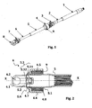
- a steering column transmission including a female flywheel pin 1 , an upper shaft 2 , a cardan joint upper jaw 3 , a lower universal joint jaw 4 , a hollow lower female shaft 5 , a lower male shaft 6 , an upper universal joint jaw 7 and a lower universal joint jaw side 8 .
- a filtering elastic sleeve 9 is interposed between the lower universal joint jaw 4 and the shaft 5 .
- the jaw 4 is constituted by a metal piece defining a reference geometric axis XX .
- the part is shaped so as to define two branches 4.1 facing one another and having two coaxial bores 4.2 for mounting a universal joint, 4.3 clearance cutouts are provided between the two branches 4.1.
- the other axial end of the jaw forms a cylindrical hub 4.4.
- An intermediate partition 4.5 perpendicular to the reference axis XX partially closes the cylindrical hub delimiting a circular axial hole 4.6 and materializing two tabs 4.7 projecting radially into the hole 4.6 .
- the assembly between the jaw 4 , the shaft 5 and the filter sleeve 9 is illustrated in more detail on the figures 2 and 6 .
- the shaft 5 is engaged inside the hole 4.6 with a radial clearance.
- the elastic filtering sleeve 9 is pressed tight on the shaft 5 and in the hub 4.4 which have for this purpose cylindrical bearing surfaces 5.1 and 4.8 facing each other.
- the shaft 5 has an end edge 5.2 and two notches 5.3 of generally rectangular shape, which face each other and extend from the edge 5.2 through the hole 4.6 and parallel to the reference axis XX of the part and other of the partition 4.5.
- Each notch has a bottom wall 5.31 and side walls 5.32 which face each other at a distance from each other so as to accommodate one of the radial tabs 4.7 formed by the intermediate partition 4.5 .
- the edge 5.2 of the shaft is locally shaped so as to have four tabs 5.4 , two to two symmetrical with respect to the axis XX , projecting radially outwards, and arranged inside a cylindrical geometric envelope having an outside diameter greater than the diameter of the hole.
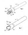
- the shaft 5 before its introduction into the jaw 4 .
- the edge is free of tabs and the tubular end of the shaft has a section compatible with its insertion into the hole 4.6 .
- the 5.4 tabs visible on the figure 6 are thus shaped after the shaft has been inserted into the hole 4.6 , when fitting of the shaft 5 (bearing possibly the sleeve 9 already fitted tight on the scope 5.1 ) in the jaw.
- the tongues 5.4 may be shaped for example by crimping, hammering, pegging, or more generally by any mechanical stress with or without a heat treatment, and to induce permanent plastic deformation of the tongues radially outwardly.
- the filtering elastic sleeve 9 comprises a cylindrical element of rubber or relatively thick elastomeric material 9.1 , preferably sheathed internally and externally by two rigid rings 9.2, 9.3.
- the functional clearances can be dimensioned so that throughout the entire operating range provided, the entire torque is transmitted by the filtering elastic sleeve, without contact between the shaft 5 and the jaw 4 . It is also preferable to dimension the functional clearances such that for extreme stresses, axial or radial contact between the shaft 5 and the jaw 4 is possible, so that a part of the torque or forces is transmitted directly by the parts. metal. This latter solution offers the advantage of avoiding possible deterioration of the filter sleeve 9 under extreme conditions, for example in the event of a steering wheel striking a sidewalk.
- the tongues 5.4 and the lugs 4.7 cooperating respectively with the intermediate partition 4.5 and with the partitions 5.31, 5.32 of the notch, locate the tree in the jaw. It is then still possible to transmit, although in a degraded mode of operation, a torque and a rotation of the steering wheel to the steering wheels of the vehicle.
- the positioning and the number of tongues 5.4 can be chosen according to the dimensions of the pieces. One can also consider a uniform deformation of the entire 5.2 edge of the shaft outward rather than local deformations.
- the tree can be full except at its end which remains tubular.
Landscapes
- Engineering & Computer Science (AREA)
- Mechanical Engineering (AREA)
- General Engineering & Computer Science (AREA)
- Chemical & Material Sciences (AREA)
- Combustion & Propulsion (AREA)
- Transportation (AREA)
- Steering Controls (AREA)
Description
- L'invention se rapporte à un assemblage entre une mâchoire d'un joint de cardan et un arbre de colonne de direction avec interposition d'un manchon filtrant les bruits et vibrations.
- La colonne de direction est le mécanisme qui permet de transmettre le mouvement de rotation du volant à la crémaillère de direction d'un véhicule. Elle peut être munie d'un élément filtrant qui permet de filtrer les vibrations provenant de la route et du moteur via le berceau avant. Cet élément filtrant est souvent constitué par un manchon élastique interposé en série entre deux éléments de la colonne, généralement entre un arbre plein ou creux et une mâchoire de joint de cardan. En cas de détérioration de l'élément filtrant il convient de sécuriser la liaison pour assurer la transmission du couple entre le volant et la crémaillère de direction. Ainsi est-il proposé dans le document
FR 2 464 404 - Dans le document
FR 2 816 677 - Dans le document
DE 198 21 503 est décrit un autre assemblage entre une extrémité d'arbre de section non circulaire et une pièce formant mâchoire de joint de cardan, présentant également une difficulté d'indexation angulaire de l'arbre par rapport à la mâchoire au moment du montage. - L'invention vise à remédier aux inconvénients de l'état de la technique et à proposer un assemblage élastique simplifié entre une mâchoire de joint de cardan et un arbre de colonne de direction, qui se prête à un assemblage automatique ou semi-automatique à cadence élevée, tout en assurant, en cas de destruction de l'élément élastique, un fonctionnement en mode dégradé satisfaisant.
- Pour ce faire est proposé, selon un premier aspect de l'invention, un assemblage d'un arbre avec une mâchoire de joint de cardan constituée par une pièce métallique définissant un axe géométrique de référence et présentant une première extrémité façonnée de manière à définir deux branches de montage d'un croisillon de joint de cardan et des découpes de débattement, une deuxième extrémité formant un moyeu cylindrique, un manchon élastique étant emmanché serré sur l'arbre et dans le moyeu, l'arbre présentant une extrémité axiale tubulaire faisant saillie depuis le manchon élastique vers les branches, l'extrémité tubulaire de l'arbre présentant au moins un relief de localisation venant latéralement en regard et à distance d'au moins un relief complémentaire de la mâchoire, le relief de localisation et le relief complémentaire étant conformés de manière à pouvoir s'interpénétrer par un mouvement relatif axial entre l'arbre et la mâchoire pour limiter les mouvements relatifs de rotation autour de l'axe de référence entre l'arbre et la mâchoire et pour limiter les mouvements relatif axiaux entre l'arbre et la mâchoire dans un sens d'interpénétration. La mâchoire comporte en outre une cloison intermédiaire s'étendant perpendiculairement à l'axe de référence dans une position intermédiaire entre le moyeu et les branches, la cloison intermédiaire fermant partiellement le moyeu et étant pourvue d'un trou de passage pour l'extrémité tubulaire de l'arbre et en ce que l'extrémité axiale de l'arbre présente au moins localement un rabat de matière qui est rabattu radialement vers l'extérieur de manière à former une butée axiale coopérant avec la cloison intermédiaire pour limiter les mouvements axiaux relatif entre l'arbre et la mâchoire dans un sens d'extraction opposé au sens d'interpénétration. Le relief de localisation comporte une encoche ouverte à l'extrémité axiale ou une patte faisant saillie axialement, le relief complémentaire étant constitué par des formes spécifiques du trou incluant une patte complémentaire ou une encoche complémentaire de la mâchoire.
- L'assemblage peut aisément être fabriqué à partir des trois pièces constituées par le manchon, l'arbre sur lequel le rabat de matière n'a pas encore été formé, et la mâchoire. Il suffit dans un premier temps d'emmancher ensemble les trois pièces, en une ou deux étapes successives (le manchon sur l'arbre, puis le tout dans le moyeu de la mâchoire, ou le manchon dans le moyeu de la mâchoire, puis le tout sur l'arbre, ou les deux emmanchements faits conjointement), puis dans un deuxième temps, de former le ou les rabats de matière. Il est à noter que la forme du ou des reliefs de localisation et du ou des reliefs complémentaires sont choisies pour que ceux-ci s'interpénètrent au moment de l'emmanchement du simple fait du mouvement axial d'emmanchement.
- Les mouvements axiaux relatifs entre l'arbre et la mâchoire sont limités de manière à autoriser un débattement axial relatif entre l'arbre et la mâchoire. Ce débattement est suffisant pour permettre au manchon élastique d'assurer sa fonction, mais suffisamment faible pour qu'en cas de détérioration ou rupture du manchon élastique, une localisation axiale soit assurée dans les deux sens. Pour protéger le manchon élastique, on pourra prévoir que le débattement axial relatif autorisé reste inférieur à la limite de déformation élastique axiale du manchon.
- De même, les mouvements rotatifs relatifs entre l'arbre et la mâchoire sont limités de manière à autoriser un débattement angulaire relatif entre l'arbre et la mâchoire. Ce débattement angulaire est suffisant pour permettre au manchon élastique d'assurer sa fonction, mais suffisamment faible pour qu'en cas de détérioration ou rupture du manchon élastique, une localisation angulaire soit assurée dans les deux sens. Pour protéger le manchon élastique, on pourra prévoir que le débattement angulaire relatif autorisé reste inférieur à la limite de déformation élastique en torsion du manchon.
- De manière préférentielle, le manchon élastique comporte au moins un élément cylindrique en caoutchouc ou en matériau élastomère. Cet élément cylindrique en caoutchouc peut être disposé entre une bague intérieure rigide et une bague extérieure rigide.
- Naturellement, le nombre de reliefs de localisation et de reliefs complémentaires peut être multiplié. Pour un arbre aux dimensions habituellement rencontrées dans les applications automobiles concernées, deux encoches diamétralement opposées coopérant chacune avec une patte s'avèrent particulièrement adaptées.
- L'arbre peut être plein ou creux, le cas échéant cannelé intérieurement ou extérieurement
- Selon un autre aspect de l'invention, celle-ci a trait à un procédé de montage de l'assemblage précédemment défini suivant lequel, après avoir emmanché le manchon élastique, l'arbre et le moyeu de telle manière que l'extrémité de l'arbre émerge du trou du côté de la cloison intermédiaire opposé au moyeu, on déforme le bord d'extrémité de l'arbre radialement vers l'extérieur pour former le rabat de matière. L'ordre des opérations d'emmanchement (manchon sur arbre, puis dans le moyeu, ou manchon dans le moyeu puis sur l'arbre, ou les deux emmanchements faits simultanément) est indifférent. La déformation peut être faite notamment par sertissage, bouterollage, martelage, ou emboutissage.
- D'autres caractéristiques et avantages de l'invention ressortiront à la lecture de la description qui suit, en référence aux figures annexées, qui illustrent :
- la
figure 1 , une vue en perspective une transmission de colonne de direction ; - la
figure 2 , une vue en coupe de l'assemblage selon l'invention entre une mâchoire de joint de cardan et un arbre de la colonne de direction de lafigure 1 ; - la
figure 3 , une vue en perspective d'un manchon filtrant de l'assemblage de lafigure 2 ; - la
figure 4 , une vue en perspective de la mâchoire de joint de cardan de lafigure 2 ; - la
figure 5 , une autre vue en perspective de la mâchoire de joint de cardan de lafigure 2 ; - la
figure 6 , une vue en perspective de l'assemblage de lafigure 2 ; - la
figure 7 , une vue en perspective de l'arbre de lafigure 2 , avant son assemblage avec la mâchoire. - Pour plus de clarté, les éléments identiques sont repérés par des signes de référence identiques sur l'ensemble des figures.
- Sur la
figure 1 est illustrée une transmission de colonne de direction comprenant notamment un axe volant femelle 1, un arbre supérieur 2, une mâchoire supérieure de joint de cardan 3, une mâchoire inférieure de joint de cardan 4, un arbre inférieur femelle creux 5, un arbre inférieur mâle 6, une mâchoire de joint de cardan supérieure 7 et une mâchoire de joint de cardan inférieure côté pignon 8. Un manchon élastique filtrant 9 est interposé entre la mâchoire inférieure de joint de cardan 4 et l'arbre 5. - La mâchoire 4, visible en détail sur les
figures 4 et 5 , est constituée par une pièce métallique définissant un axe géométrique X-X de référence. A une extrémité axiale, la pièce est façonnée de manière à définir deux branches 4.1 en regard l'une de l'autre et présentant deux alésages coaxiaux 4.2 de montage d'un croisillon de joint de cardan, des découpes de débattement 4.3 étant prévues entre les deux branches 4.1. L'autre extrémité axiale de la mâchoire forme un moyeu cylindrique 4.4. Une cloison intermédiaire 4.5 perpendiculaire à l'axe de référence X-X, ferme partiellement le moyeu cylindrique en délimitant un trou axial circulaire 4.6 et en matérialisant deux pattes 4.7 faisant saillie radialement dans ce trou 4.6. - L'assemblage entre la mâchoire 4, l'arbre 5 et le manchon filtrant 9 est illustré plus en détail sur les
figures 2 et6 . L'arbre 5 est engagé à l'intérieur du trou 4.6 avec un jeu radial. Le manchon élastique filtrant 9 est emmanché serré sur l'arbre 5 et dans le moyeu 4.4 qui présentent à cet effet des portées cylindriques 5.1 et 4.8 en regard l'une de l'autre. L'arbre 5 présente un bord d'extrémité 5.2 et deux encoches 5.3 de forme générale rectangulaire, qui se font face et s'étendent depuis le bord 5.2 au travers du trou 4.6 et parallèlement à l'axe de référence X-X de part et d'autre de la cloison 4.5. Chaque encoche présente une cloison de fond 5.31 et des cloisons latérales 5.32 qui se font face à distances l'une de l'autre de manière à pouvoir accueillir une des pattes radiales 4.7 formée par la cloison intermédiaire 4.5. - Le bord 5.2 de l'arbre est localement façonné de manière à présenter quatre languettes 5.4, deux à deux symétriques par rapport à l'axe X-X, faisant saillie radialement vers l'extérieur, et disposées à l'intérieur d'une enveloppe géométrique cylindrique ayant un diamètre extérieur supérieur au diamètre du trou.
- On a représenté sur la
figure 7 l'arbre 5 avant son introduction dans la mâchoire 4. Comme on peut le constater dans cet état avant montage, le bord est exempt de languettes et l'extrémité tubulaire de l'arbre a une section compatible avec son insertion dans le trou 4.6. Les languettes 5.4 visibles sur lafigure 6 sont donc façonnées après que l'arbre a été introduit dans le trou 4.6, lors de l'emmanchement de l'arbre 5 (portant le cas échéant le manchon 9 déjà emmanché serré sur la portée 5.1) dans la mâchoire. Les languettes 5.4 peuvent être façonnée par exemple par sertissage, martelage, bouterollage, ou plus généralement par toute sollicitation mécanique accompagnée ou non d'un traitement thermique, et permettant d'induire une déformation plastique permanente des languettes radialement vers l'extérieur. - Comme illustré sur la
figure 3 , le manchon élastique filtrant 9 comporte un élément cylindrique en caoutchouc ou en matière élastomère 9.1 relativement épais, de préférence gainé intérieurement et extérieurement par deux bagues rigides 9.2, 9.3. - Dans la position nominale de la
figure 2 , les languettes sont disposées à une distance J1 de la cloison intermédiaire 4.5, alors que les pattes radiales 4.7 sont à une distance J3 du fond 5.31 des encoches et à une distance J2 des cloisons latérales 5.32 des encoches 5.3. Il existe par conséquent aussi bien en translation parallèlement à l'axe X-X qu'en rotation autour de l'axe X-X un jeu fonctionnel de débattement donnant à la mâchoire 4 des degrés de liberté de mouvement correspondants par rapport à l'arbre 5, par déformation du manchon élastique filtrant 9. - On peut dimensionner les jeux fonctionnels pour que dans toute la gamme de fonctionnement prévue, l'intégralité du couple soit transmis par le manchon élastique filtrant, sans contact entre l'arbre 5 et la mâchoire 4. On peut également préférer un dimensionnement des jeux fonctionnels tel que pour des sollicitations extrêmes, un contact axial ou radial entre l'arbre 5 et la mâchoire 4 soit possible, de sorte qu'une partie du couple ou des efforts soit transmise directement par les pièces métalliques. Cette dernière solution offre l'avantage d'éviter une détérioration possible du manchon filtrant 9 dans des conditions extrêmes, par exemple en cas de choc d'une roue directrice sur un trottoir.
- En cas de détérioration ou de destruction du manchon filtrant 9, par exemple suite à des attaques mécaniques, thermiques et/ou chimiques, les languettes 5.4 et les pattes 4.7, coopérant respectivement avec la cloison intermédiaire 4.5 et avec les cloisons 5.31, 5.32 de l'encoche, localisent l'arbre dans la mâchoire. Il est alors toujours possible de transmettre, certes dans un mode de fonctionnement dégradé, un couple et une rotation du volant aux roues directrice du véhicule.
- De nombreuses variantes sont possibles. Le positionnement et le nombre de languettes 5.4 peuvent être choisis suivant les dimensions des pièces. On peut également envisager une déformation uniforme de l'ensemble du bord 5.2 de l'arbre vers l'extérieur plutôt que des déformations locales.
- L'arbre peut être plein, sauf à son extrémité qui reste tubulaire.
Claims (7)
- Assemblage d'un arbre (5) avec une mâchoire (4) de joint de cardan constituée par une pièce métallique définissant un axe géométrique de référence (X-X) et présentant une première extrémité façonnée de manière à définir deux branches (4.1) de montage d'un croisillon de joint de cardan et des découpes de débattement (4.2), une deuxième extrémité formant un moyeu cylindrique (4.4), un manchon élastique (9) étant emmanché sur l'arbre (5) et dans le moyeu (4.4), l'arbre présentant une extrémité axiale tubulaire faisant saillie depuis le manchon élastique (9) vers les branches (4.1), l'extrémité tubulaire de l'arbre (5) présentant au moins un relief de localisation (5.3) venant latéralement en regard et à distance d'au moins un relief complémentaire (4.7) de la mâchoire, le relief de localisation (5.3) et le relief complémentaire (4.7) étant conformés de manière à pouvoir s'interpénétrer par un mouvement relatif axial entre l'arbre (5) et la mâchoire (4) pour limiter les mouvements rotatifs relatifs autour de l'axe de référence entre l'arbre (5) et la mâchoire (4) et pour limiter les mouvements relatif axiaux entre l'arbre (5) et la mâchoire (4) dans un sens d'interpénétration,
la mâchoire (4) comportant en outre une cloison intermédiaire (4.5) s'étendant perpendiculairement à l'axe de référence (X-X) dans une position intermédiaire entre le moyeu (4.4) et les branches (4.1), la cloison intermédiaire (4.5) fermant partiellement le moyeu et étant pourvue d'un trou (4.6) de passage pour l'extrémité tubulaire de l'arbre, et l'extrémité tubulaire de l'arbre présentant au moins localement un rabat de matière (5.4) qui est rabattu radialement vers l'extérieur de manière à former une butée axiale coopérant avec la cloison intermédiaire (4.5) pour limiter les mouvements axiaux relatif entre l'arbre et la mâchoire dans un sens d'extraction opposé au sens d'interpénétration, caractérisé en ce que
le manchon élastique (9) est cylindrique et emmanché sur une portée cylindrique (5.1) de l'arbre (5) et dans une portée cylindrique (4.8) du moyeu (4.4),
le relief de localisation comporte une encoche (5.3) ouverte à l'extrémité axiale ou une patte faisant saillie axialement, et
le relief complémentaire est constitué par des formes spécifiques du trou (4.6) et comporte une patte complémentaire (4.7) ou une encoche complémentaire de la mâchoire. - Assemblage selon la revendication 1, caractérisé en ce que les mouvements axiaux relatifs entre l'arbre (5) et la mâchoire (4) sont limités de manière à autoriser un débattement axial relatif entre l'arbre (5) et la mâchoire (4).
- Assemblage selon la revendication 2, caractérisé en ce que le débattement axial relatif autorisé est inférieur à la limite de déformation élastique axiale du manchon (9).
- Assemblage selon l'une quelconque des revendications précédentes, caractérisé en ce que les mouvements rotatifs relatifs entre l'arbre (5) et la mâchoire (4) sont limités de manière à autoriser un débattement angulaire relatif entre l'arbre (5) et la mâchoire (4).
- Assemblage selon la revendication 4, caractérisé en ce que lé débattement angulaire relatif autorisé est inférieur à la limite de déformation élastique en torsion du manchon (9).
- Procédé de montage d'un assemblage selon l'une quelconque des revendications précédentes, caractérisé en ce que, après avoir emmanché le manchon élastique (9), l'arbre (5) et le moyeu (4.4), de telle manière que l'extrémité de l'arbre émerge du trou (4.6) du côté de la cloison intermédiaire (4.5) opposé au moyeu (4.4), on déforme l'extrémité de l'arbre radialement vers l'extérieur pour former le rabat de matière (5.4).
- Procédé de montage selon la revendication 6, caractérisé en ce que la déformation est faite par sertissage, bouterollage, martelage, ou emboutissage.
Applications Claiming Priority (2)
| Application Number | Priority Date | Filing Date | Title |
|---|---|---|---|
| FR1251599A FR2987089B1 (fr) | 2012-02-22 | 2012-02-22 | Assemblage elastique d’une machoire de joint de cardan avec un arbre de colonne de direction |
| PCT/EP2013/053583 WO2013124427A1 (fr) | 2012-02-22 | 2013-02-22 | Assemblage elastique d'une machoire de joint de cardan avec un arbre de colonne de direction |
Publications (2)
| Publication Number | Publication Date |
|---|---|
| EP2817198A1 EP2817198A1 (fr) | 2014-12-31 |
| EP2817198B1 true EP2817198B1 (fr) | 2015-11-04 |
Family
ID=47748619
Family Applications (1)
| Application Number | Title | Priority Date | Filing Date |
|---|---|---|---|
| EP13705779.0A Active EP2817198B1 (fr) | 2012-02-22 | 2013-02-22 | Assemblage elastique d'une machoire de joint de cardan avec un arbre de colonne de direction |
Country Status (5)
| Country | Link |
|---|---|
| EP (1) | EP2817198B1 (fr) |
| CN (1) | CN104136307B (fr) |
| BR (1) | BR112014018619A8 (fr) |
| FR (1) | FR2987089B1 (fr) |
| WO (1) | WO2013124427A1 (fr) |
Families Citing this family (4)
| Publication number | Priority date | Publication date | Assignee | Title |
|---|---|---|---|---|
| CZ2014164A3 (cs) * | 2014-03-19 | 2015-10-14 | Zlkl, S.R.O. | Výsuvná spojovací tyč řízení |
| CN106829582A (zh) * | 2017-01-12 | 2017-06-13 | 芜湖航天特种电缆厂股份有限公司 | 膜切割装置 |
| CN106743864A (zh) * | 2017-01-12 | 2017-05-31 | 芜湖航天特种电缆厂股份有限公司 | 膜切割装置 |
| CN108995704A (zh) * | 2017-06-07 | 2018-12-14 | 株式会社万都 | 连接件 |
Family Cites Families (7)
| Publication number | Priority date | Publication date | Assignee | Title |
|---|---|---|---|---|
| FR2464404A1 (fr) | 1979-09-04 | 1981-03-06 | Nadella | Dispositif d'accouplement elastique a effet d'entrainement permanent |
| US5259818A (en) * | 1989-04-14 | 1993-11-09 | Fuji Kiko Company, Limited | Stroke absorbing type intermediate shaft for vehicular steering column and method for assembling the same |
| GB2296071B (en) * | 1994-12-16 | 1999-01-13 | Nsk Ltd | Elastic universal joint |
| JP3627441B2 (ja) * | 1997-05-16 | 2005-03-09 | 日本精工株式会社 | 弾性軸継手 |
| US5956836A (en) * | 1998-05-04 | 1999-09-28 | General Motors Corporation | Method of making a torsional damper |
| FR2816677B1 (fr) * | 2000-11-15 | 2003-02-28 | Delphi Tech Inc | Arbre a fourchette, et organe de liaison pour l'assemblage d'un arbre a fourchette |
| CN201133426Y (zh) * | 2007-12-07 | 2008-10-15 | 浙江吉利汽车研究院有限公司 | 汽车转向下轴万向节 |
-
2012
- 2012-02-22 FR FR1251599A patent/FR2987089B1/fr not_active Expired - Fee Related
-
2013
- 2013-02-22 EP EP13705779.0A patent/EP2817198B1/fr active Active
- 2013-02-22 CN CN201380010155.7A patent/CN104136307B/zh active Active
- 2013-02-22 WO PCT/EP2013/053583 patent/WO2013124427A1/fr not_active Ceased
- 2013-02-22 BR BR112014018619A patent/BR112014018619A8/pt not_active Application Discontinuation
Also Published As
| Publication number | Publication date |
|---|---|
| CN104136307B (zh) | 2016-10-26 |
| FR2987089B1 (fr) | 2015-02-27 |
| WO2013124427A1 (fr) | 2013-08-29 |
| BR112014018619A2 (fr) | 2017-06-20 |
| CN104136307A (zh) | 2014-11-05 |
| EP2817198A1 (fr) | 2014-12-31 |
| FR2987089A1 (fr) | 2013-08-23 |
| BR112014018619A8 (pt) | 2017-07-11 |
Similar Documents
| Publication | Publication Date | Title |
|---|---|---|
| EP3121481B1 (fr) | Dispositif d amortissement de torsion pour un systeme de transmission de vehicule automobile | |
| EP0211701B2 (fr) | Dispositif amortisseur de torsion, notamment pour embrayage de véhicule automobile, à amortissement au moins partiellement dû à un élément élastomère | |
| WO2013174616A1 (fr) | Dispositif de transmission de couple pour vehicule automobile | |
| FR2988455A1 (fr) | Dispositif de transmission de couple pour un vehicule automobile | |
| FR2694966A1 (fr) | Agencement de palier pour dispositif comprenant deux éléments de construction rotatifs. | |
| WO2013124427A1 (fr) | Assemblage elastique d'une machoire de joint de cardan avec un arbre de colonne de direction | |
| WO1996035890A1 (fr) | Appareil d'accouplement hydrocinetique, notamment pour vehicule automobile | |
| FR3039240A1 (fr) | Double volant amortisseur comportant une rondelle d'obturation apte a assurer l'etancheite du volant primaire | |
| EP1852632B1 (fr) | Embrayage à friction perferctionné, en particulier pour véhicule automobile, rondelle de guidage d'amortisseur d'embrayage à friction, et procédé de montage d'un embrayage à friction | |
| WO1998014719A1 (fr) | Double volant amortisseur, notamment pour vehicule automobile, comportant des moyens perfectionnes d'amortissement par friction des vibrations | |
| EP3899317B1 (fr) | Dispositif de transmission de couple avec des ressorts en serie et systeme de transmission de couple comprenant un tel dispositif | |
| WO2017212169A1 (fr) | Dispositif d'amortissement | |
| WO2016030615A1 (fr) | Dispositif de transmission de couple pour un véhicule automobile | |
| FR3020425A1 (fr) | Dispositif de transmission de couple pour un vehicule automobile | |
| EP0239457B1 (fr) | Volant amortisseur pour transmission, notamment pour véhicule automobile | |
| WO1996007837A1 (fr) | Volant amortisseur, notamment pour vehicule automobile | |
| WO2024003269A1 (fr) | Pales de butee de ressorts fixees sur un volant amortisseur | |
| EP0836685B1 (fr) | Montage de butee de debrayage | |
| FR3064036A1 (fr) | Disque d'embrayage avec rondelle de frottement | |
| EP2098756A1 (fr) | Dispositif d'amortissement comportant un système d'amortissement des vibrations formé par un batteur inertiel | |
| WO2017174583A1 (fr) | Ensemble pour dispositif de transmission de couple, dispositif de transmission de couple, et leurs procedes de montage | |
| EP3889459B1 (fr) | Disque de frottement pour amortisseur de torsion | |
| EP3404278A1 (fr) | Dispositif d' accommodation des desalignements entre le vilebrequin et l arbre d'entree de la boite de vitesse et disque de friction equipe d'un tel dispositif | |
| EP4375535A1 (fr) | Guidage et butees des organes élastiques dans un volant moteur | |
| FR2841522A1 (fr) | Colonne de direction a moyens de retenue de roulement, procede de realisation, ensemble de direction et vehicule automobile correspondants |
Legal Events
| Date | Code | Title | Description |
|---|---|---|---|
| PUAI | Public reference made under article 153(3) epc to a published international application that has entered the european phase |
Free format text: ORIGINAL CODE: 0009012 |
|
| 17P | Request for examination filed |
Effective date: 20140624 |
|
| AK | Designated contracting states |
Kind code of ref document: A1 Designated state(s): AL AT BE BG CH CY CZ DE DK EE ES FI FR GB GR HR HU IE IS IT LI LT LU LV MC MK MT NL NO PL PT RO RS SE SI SK SM TR |
|
| AX | Request for extension of the european patent |
Extension state: BA ME |
|
| REG | Reference to a national code |
Ref country code: DE Ref legal event code: R079 Ref document number: 602013003773 Country of ref document: DE Free format text: PREVIOUS MAIN CLASS: B62D0007220000 Ipc: B62D0001160000 |
|
| RIC1 | Information provided on ipc code assigned before grant |
Ipc: B62D 1/16 20060101AFI20150317BHEP Ipc: F16D 3/38 20060101ALI20150317BHEP Ipc: F16D 3/76 20060101ALI20150317BHEP Ipc: B62D 7/22 20060101ALI20150317BHEP |
|
| DAX | Request for extension of the european patent (deleted) | ||
| GRAP | Despatch of communication of intention to grant a patent |
Free format text: ORIGINAL CODE: EPIDOSNIGR1 |
|
| INTG | Intention to grant announced |
Effective date: 20150529 |
|
| GRAS | Grant fee paid |
Free format text: ORIGINAL CODE: EPIDOSNIGR3 |
|
| GRAP | Despatch of communication of intention to grant a patent |
Free format text: ORIGINAL CODE: EPIDOSNIGR1 |
|
| RAP1 | Party data changed (applicant data changed or rights of an application transferred) |
Owner name: ROBERT BOSCH AUTOMOTIVE STEERING VENDOME |
|
| GRAA | (expected) grant |
Free format text: ORIGINAL CODE: 0009210 |
|
| INTG | Intention to grant announced |
Effective date: 20150917 |
|
| AK | Designated contracting states |
Kind code of ref document: B1 Designated state(s): AL AT BE BG CH CY CZ DE DK EE ES FI FR GB GR HR HU IE IS IT LI LT LU LV MC MK MT NL NO PL PT RO RS SE SI SK SM TR |
|
| REG | Reference to a national code |
Ref country code: GB Ref legal event code: FG4D Free format text: NOT ENGLISH |
|
| REG | Reference to a national code |
Ref country code: CH Ref legal event code: EP |
|
| REG | Reference to a national code |
Ref country code: AT Ref legal event code: REF Ref document number: 758965 Country of ref document: AT Kind code of ref document: T Effective date: 20151115 |
|
| REG | Reference to a national code |
Ref country code: IE Ref legal event code: FG4D Free format text: LANGUAGE OF EP DOCUMENT: FRENCH |
|
| REG | Reference to a national code |
Ref country code: DE Ref legal event code: R096 Ref document number: 602013003773 Country of ref document: DE |
|
| REG | Reference to a national code |
Ref country code: FR Ref legal event code: PLFP Year of fee payment: 4 |
|
| REG | Reference to a national code |
Ref country code: NL Ref legal event code: MP Effective date: 20151104 |
|
| REG | Reference to a national code |
Ref country code: LT Ref legal event code: MG4D |
|
| REG | Reference to a national code |
Ref country code: AT Ref legal event code: MK05 Ref document number: 758965 Country of ref document: AT Kind code of ref document: T Effective date: 20151104 |
|
| PG25 | Lapsed in a contracting state [announced via postgrant information from national office to epo] |
Ref country code: IT Free format text: LAPSE BECAUSE OF FAILURE TO SUBMIT A TRANSLATION OF THE DESCRIPTION OR TO PAY THE FEE WITHIN THE PRESCRIBED TIME-LIMIT Effective date: 20151104 Ref country code: NL Free format text: LAPSE BECAUSE OF FAILURE TO SUBMIT A TRANSLATION OF THE DESCRIPTION OR TO PAY THE FEE WITHIN THE PRESCRIBED TIME-LIMIT Effective date: 20151104 Ref country code: NO Free format text: LAPSE BECAUSE OF FAILURE TO SUBMIT A TRANSLATION OF THE DESCRIPTION OR TO PAY THE FEE WITHIN THE PRESCRIBED TIME-LIMIT Effective date: 20160204 Ref country code: IS Free format text: LAPSE BECAUSE OF FAILURE TO SUBMIT A TRANSLATION OF THE DESCRIPTION OR TO PAY THE FEE WITHIN THE PRESCRIBED TIME-LIMIT Effective date: 20160304 Ref country code: ES Free format text: LAPSE BECAUSE OF FAILURE TO SUBMIT A TRANSLATION OF THE DESCRIPTION OR TO PAY THE FEE WITHIN THE PRESCRIBED TIME-LIMIT Effective date: 20151104 Ref country code: LT Free format text: LAPSE BECAUSE OF FAILURE TO SUBMIT A TRANSLATION OF THE DESCRIPTION OR TO PAY THE FEE WITHIN THE PRESCRIBED TIME-LIMIT Effective date: 20151104 Ref country code: HR Free format text: LAPSE BECAUSE OF FAILURE TO SUBMIT A TRANSLATION OF THE DESCRIPTION OR TO PAY THE FEE WITHIN THE PRESCRIBED TIME-LIMIT Effective date: 20151104 |
|
| PG25 | Lapsed in a contracting state [announced via postgrant information from national office to epo] |
Ref country code: RS Free format text: LAPSE BECAUSE OF FAILURE TO SUBMIT A TRANSLATION OF THE DESCRIPTION OR TO PAY THE FEE WITHIN THE PRESCRIBED TIME-LIMIT Effective date: 20151104 Ref country code: LV Free format text: LAPSE BECAUSE OF FAILURE TO SUBMIT A TRANSLATION OF THE DESCRIPTION OR TO PAY THE FEE WITHIN THE PRESCRIBED TIME-LIMIT Effective date: 20151104 Ref country code: PL Free format text: LAPSE BECAUSE OF FAILURE TO SUBMIT A TRANSLATION OF THE DESCRIPTION OR TO PAY THE FEE WITHIN THE PRESCRIBED TIME-LIMIT Effective date: 20151104 Ref country code: PT Free format text: LAPSE BECAUSE OF FAILURE TO SUBMIT A TRANSLATION OF THE DESCRIPTION OR TO PAY THE FEE WITHIN THE PRESCRIBED TIME-LIMIT Effective date: 20160304 Ref country code: FI Free format text: LAPSE BECAUSE OF FAILURE TO SUBMIT A TRANSLATION OF THE DESCRIPTION OR TO PAY THE FEE WITHIN THE PRESCRIBED TIME-LIMIT Effective date: 20151104 Ref country code: GR Free format text: LAPSE BECAUSE OF FAILURE TO SUBMIT A TRANSLATION OF THE DESCRIPTION OR TO PAY THE FEE WITHIN THE PRESCRIBED TIME-LIMIT Effective date: 20160205 Ref country code: SE Free format text: LAPSE BECAUSE OF FAILURE TO SUBMIT A TRANSLATION OF THE DESCRIPTION OR TO PAY THE FEE WITHIN THE PRESCRIBED TIME-LIMIT Effective date: 20151104 Ref country code: BE Free format text: LAPSE BECAUSE OF NON-PAYMENT OF DUE FEES Effective date: 20160229 Ref country code: AT Free format text: LAPSE BECAUSE OF FAILURE TO SUBMIT A TRANSLATION OF THE DESCRIPTION OR TO PAY THE FEE WITHIN THE PRESCRIBED TIME-LIMIT Effective date: 20151104 |
|
| PG25 | Lapsed in a contracting state [announced via postgrant information from national office to epo] |
Ref country code: CZ Free format text: LAPSE BECAUSE OF FAILURE TO SUBMIT A TRANSLATION OF THE DESCRIPTION OR TO PAY THE FEE WITHIN THE PRESCRIBED TIME-LIMIT Effective date: 20151104 |
|
| REG | Reference to a national code |
Ref country code: DE Ref legal event code: R097 Ref document number: 602013003773 Country of ref document: DE |
|
| PG25 | Lapsed in a contracting state [announced via postgrant information from national office to epo] |
Ref country code: SK Free format text: LAPSE BECAUSE OF FAILURE TO SUBMIT A TRANSLATION OF THE DESCRIPTION OR TO PAY THE FEE WITHIN THE PRESCRIBED TIME-LIMIT Effective date: 20151104 Ref country code: EE Free format text: LAPSE BECAUSE OF FAILURE TO SUBMIT A TRANSLATION OF THE DESCRIPTION OR TO PAY THE FEE WITHIN THE PRESCRIBED TIME-LIMIT Effective date: 20151104 Ref country code: SM Free format text: LAPSE BECAUSE OF FAILURE TO SUBMIT A TRANSLATION OF THE DESCRIPTION OR TO PAY THE FEE WITHIN THE PRESCRIBED TIME-LIMIT Effective date: 20151104 Ref country code: DK Free format text: LAPSE BECAUSE OF FAILURE TO SUBMIT A TRANSLATION OF THE DESCRIPTION OR TO PAY THE FEE WITHIN THE PRESCRIBED TIME-LIMIT Effective date: 20151104 Ref country code: RO Free format text: LAPSE BECAUSE OF FAILURE TO SUBMIT A TRANSLATION OF THE DESCRIPTION OR TO PAY THE FEE WITHIN THE PRESCRIBED TIME-LIMIT Effective date: 20151104 |
|
| PLBE | No opposition filed within time limit |
Free format text: ORIGINAL CODE: 0009261 |
|
| STAA | Information on the status of an ep patent application or granted ep patent |
Free format text: STATUS: NO OPPOSITION FILED WITHIN TIME LIMIT |
|
| PG25 | Lapsed in a contracting state [announced via postgrant information from national office to epo] |
Ref country code: MC Free format text: LAPSE BECAUSE OF FAILURE TO SUBMIT A TRANSLATION OF THE DESCRIPTION OR TO PAY THE FEE WITHIN THE PRESCRIBED TIME-LIMIT Effective date: 20151104 Ref country code: LU Free format text: LAPSE BECAUSE OF FAILURE TO SUBMIT A TRANSLATION OF THE DESCRIPTION OR TO PAY THE FEE WITHIN THE PRESCRIBED TIME-LIMIT Effective date: 20160222 |
|
| REG | Reference to a national code |
Ref country code: CH Ref legal event code: PL |
|
| 26N | No opposition filed |
Effective date: 20160805 |
|
| PG25 | Lapsed in a contracting state [announced via postgrant information from national office to epo] |
Ref country code: LI Free format text: LAPSE BECAUSE OF NON-PAYMENT OF DUE FEES Effective date: 20160229 Ref country code: CH Free format text: LAPSE BECAUSE OF NON-PAYMENT OF DUE FEES Effective date: 20160229 |
|
| PG25 | Lapsed in a contracting state [announced via postgrant information from national office to epo] |
Ref country code: SI Free format text: LAPSE BECAUSE OF FAILURE TO SUBMIT A TRANSLATION OF THE DESCRIPTION OR TO PAY THE FEE WITHIN THE PRESCRIBED TIME-LIMIT Effective date: 20151104 |
|
| REG | Reference to a national code |
Ref country code: IE Ref legal event code: MM4A |
|
| PG25 | Lapsed in a contracting state [announced via postgrant information from national office to epo] |
Ref country code: IE Free format text: LAPSE BECAUSE OF NON-PAYMENT OF DUE FEES Effective date: 20160222 |
|
| REG | Reference to a national code |
Ref country code: FR Ref legal event code: PLFP Year of fee payment: 5 |
|
| PGFP | Annual fee paid to national office [announced via postgrant information from national office to epo] |
Ref country code: GB Payment date: 20170626 Year of fee payment: 5 |
|
| PG25 | Lapsed in a contracting state [announced via postgrant information from national office to epo] |
Ref country code: MT Free format text: LAPSE BECAUSE OF FAILURE TO SUBMIT A TRANSLATION OF THE DESCRIPTION OR TO PAY THE FEE WITHIN THE PRESCRIBED TIME-LIMIT Effective date: 20151104 |
|
| REG | Reference to a national code |
Ref country code: FR Ref legal event code: PLFP Year of fee payment: 6 |
|
| PG25 | Lapsed in a contracting state [announced via postgrant information from national office to epo] |
Ref country code: HU Free format text: LAPSE BECAUSE OF FAILURE TO SUBMIT A TRANSLATION OF THE DESCRIPTION OR TO PAY THE FEE WITHIN THE PRESCRIBED TIME-LIMIT; INVALID AB INITIO Effective date: 20130222 |
|
| PG25 | Lapsed in a contracting state [announced via postgrant information from national office to epo] |
Ref country code: MK Free format text: LAPSE BECAUSE OF FAILURE TO SUBMIT A TRANSLATION OF THE DESCRIPTION OR TO PAY THE FEE WITHIN THE PRESCRIBED TIME-LIMIT Effective date: 20151104 Ref country code: CY Free format text: LAPSE BECAUSE OF FAILURE TO SUBMIT A TRANSLATION OF THE DESCRIPTION OR TO PAY THE FEE WITHIN THE PRESCRIBED TIME-LIMIT Effective date: 20151104 |
|
| PG25 | Lapsed in a contracting state [announced via postgrant information from national office to epo] |
Ref country code: BG Free format text: LAPSE BECAUSE OF FAILURE TO SUBMIT A TRANSLATION OF THE DESCRIPTION OR TO PAY THE FEE WITHIN THE PRESCRIBED TIME-LIMIT Effective date: 20151104 |
|
| GBPC | Gb: european patent ceased through non-payment of renewal fee |
Effective date: 20180222 |
|
| PG25 | Lapsed in a contracting state [announced via postgrant information from national office to epo] |
Ref country code: AL Free format text: LAPSE BECAUSE OF FAILURE TO SUBMIT A TRANSLATION OF THE DESCRIPTION OR TO PAY THE FEE WITHIN THE PRESCRIBED TIME-LIMIT Effective date: 20151104 Ref country code: TR Free format text: LAPSE BECAUSE OF FAILURE TO SUBMIT A TRANSLATION OF THE DESCRIPTION OR TO PAY THE FEE WITHIN THE PRESCRIBED TIME-LIMIT Effective date: 20151104 |
|
| PG25 | Lapsed in a contracting state [announced via postgrant information from national office to epo] |
Ref country code: GB Free format text: LAPSE BECAUSE OF NON-PAYMENT OF DUE FEES Effective date: 20180222 |
|
| PGFP | Annual fee paid to national office [announced via postgrant information from national office to epo] |
Ref country code: FR Payment date: 20260223 Year of fee payment: 14 |
|
| PGFP | Annual fee paid to national office [announced via postgrant information from national office to epo] |
Ref country code: DE Payment date: 20260427 Year of fee payment: 14 |