EP2816708A1 - Stator core for motor and manufacturing method therefor - Google Patents
Stator core for motor and manufacturing method therefor Download PDFInfo
- Publication number
- EP2816708A1 EP2816708A1 EP13748841.7A EP13748841A EP2816708A1 EP 2816708 A1 EP2816708 A1 EP 2816708A1 EP 13748841 A EP13748841 A EP 13748841A EP 2816708 A1 EP2816708 A1 EP 2816708A1
- Authority
- EP
- European Patent Office
- Prior art keywords
- stator core
- portions
- yoke
- annular member
- attaching
- Prior art date
- Legal status (The legal status is an assumption and is not a legal conclusion. Google has not performed a legal analysis and makes no representation as to the accuracy of the status listed.)
- Granted
Links
- 238000004519 manufacturing process Methods 0.000 title claims abstract description 23
- 238000006073 displacement reaction Methods 0.000 claims abstract description 95
- 230000002093 peripheral effect Effects 0.000 claims abstract description 60
- 230000006835 compression Effects 0.000 claims abstract description 42
- 238000007906 compression Methods 0.000 claims abstract description 42
- 238000003825 pressing Methods 0.000 claims abstract description 27
- 230000004907 flux Effects 0.000 claims abstract description 24
- 238000000034 method Methods 0.000 claims description 8
- XEEYBQQBJWHFJM-UHFFFAOYSA-N Iron Chemical compound [Fe] XEEYBQQBJWHFJM-UHFFFAOYSA-N 0.000 description 10
- 230000000694 effects Effects 0.000 description 8
- 238000005304 joining Methods 0.000 description 8
- 229910052742 iron Inorganic materials 0.000 description 5
- 230000015572 biosynthetic process Effects 0.000 description 2
- 238000003475 lamination Methods 0.000 description 2
- 229910000831 Steel Inorganic materials 0.000 description 1
- 239000000543 intermediate Substances 0.000 description 1
- 239000000696 magnetic material Substances 0.000 description 1
- 230000035699 permeability Effects 0.000 description 1
- 239000010959 steel Substances 0.000 description 1
Images





Classifications
-
- H—ELECTRICITY
- H02—GENERATION; CONVERSION OR DISTRIBUTION OF ELECTRIC POWER
- H02K—DYNAMO-ELECTRIC MACHINES
- H02K1/00—Details of the magnetic circuit
- H02K1/06—Details of the magnetic circuit characterised by the shape, form or construction
- H02K1/12—Stationary parts of the magnetic circuit
- H02K1/18—Means for mounting or fastening magnetic stationary parts on to, or to, the stator structures
- H02K1/185—Means for mounting or fastening magnetic stationary parts on to, or to, the stator structures to outer stators
-
- H—ELECTRICITY
- H02—GENERATION; CONVERSION OR DISTRIBUTION OF ELECTRIC POWER
- H02K—DYNAMO-ELECTRIC MACHINES
- H02K1/00—Details of the magnetic circuit
- H02K1/06—Details of the magnetic circuit characterised by the shape, form or construction
- H02K1/12—Stationary parts of the magnetic circuit
- H02K1/18—Means for mounting or fastening magnetic stationary parts on to, or to, the stator structures
-
- H—ELECTRICITY
- H02—GENERATION; CONVERSION OR DISTRIBUTION OF ELECTRIC POWER
- H02K—DYNAMO-ELECTRIC MACHINES
- H02K1/00—Details of the magnetic circuit
- H02K1/06—Details of the magnetic circuit characterised by the shape, form or construction
- H02K1/12—Stationary parts of the magnetic circuit
- H02K1/14—Stator cores with salient poles
- H02K1/146—Stator cores with salient poles consisting of a generally annular yoke with salient poles
- H02K1/148—Sectional cores
-
- H—ELECTRICITY
- H02—GENERATION; CONVERSION OR DISTRIBUTION OF ELECTRIC POWER
- H02K—DYNAMO-ELECTRIC MACHINES
- H02K1/00—Details of the magnetic circuit
- H02K1/06—Details of the magnetic circuit characterised by the shape, form or construction
- H02K1/12—Stationary parts of the magnetic circuit
- H02K1/16—Stator cores with slots for windings
-
- H—ELECTRICITY
- H02—GENERATION; CONVERSION OR DISTRIBUTION OF ELECTRIC POWER
- H02K—DYNAMO-ELECTRIC MACHINES
- H02K15/00—Processes or apparatus specially adapted for manufacturing, assembling, maintaining or repairing of dynamo-electric machines
- H02K15/02—Processes or apparatus specially adapted for manufacturing, assembling, maintaining or repairing of dynamo-electric machines of stator or rotor bodies
-
- H—ELECTRICITY
- H02—GENERATION; CONVERSION OR DISTRIBUTION OF ELECTRIC POWER
- H02K—DYNAMO-ELECTRIC MACHINES
- H02K2213/00—Specific aspects, not otherwise provided for and not covered by codes H02K2201/00 - H02K2211/00
- H02K2213/03—Machines characterised by numerical values, ranges, mathematical expressions or similar information
Definitions
- the present invention relates to a stator core for a motor and a manufacturing method therefor.
- Patent documents 1, 2, and 3 as illustrated in FIGs. 19 to 24 .
- FIG. 19 is a partial front view illustrating a state where a stator core is fitted to a core case by shrinkage fitting
- FIG. 20 is a partial front view of the stator core
- FIG. 21 is a partial front view illustrating a state where a stator core is fitted to a core case by shrinkage fitting
- FIG. 22 is a sectional view illustrating the state where the stator core is fitted to the core case by shrinkage fitting.
- stator core divided bodies 103A, 103B, or 103C of a stator core 101 A, 101 B, or 101C are annularly joined together and fixedly put into a core case 105A, 105B, or 105C as an annular member by shrinkage fitting.
- stator core 101A of FIGs. 19 and 20 slits 101Aa are formed so as not to generate the compression stress.
- slits 101Aa are formed so as not to generate the compression stress.
- holes 103Ba or 103Ca are formed so as to reduce the compression stress.
- FIG. 23 is a partial front view illustrating a stress generating state in a state where a stator core is fitted to a core case by shrinkage fitting
- FIG. 24 is a partial front view illustrating a magnetic flux formation state in the state where the stator core is fitted to the core case by shrinkage fitting.
- a yoke portion 101 Da included in a stator core 101 D has a radial thickness "a” is formed less than a radial thickness "b" of a core case 105D.
- a problem to be solved is that the reduction of the compression stress by means of the slits or holes causes the increase in magnetic resistance to deteriorate the magnetic characteristics whereas the setting of the thicknesses of the annular member and yoke portion involves the drawback in reducing the magnetic resistance.
- the present invention provides a stator core for a motor in order to further improve the magnetic characteristics.
- the stator core includes an annular yoke portion and tooth portions protruding inwardly in a radial direction from an inner periphery of the yoke portion, wherein an outer peripheral edge of the yoke portion is attached to an inner peripheral surface of an annular member.
- the yoke portion includes displacement portions displaced by receiving radially-inward pressing force from the annular member, and deformation portions deformed according to displacements of the displacement portions to generate tensile stress so as to form tensile stress regions through which magnetic flux passes between the tooth portions and the yoke portion or so as to counterbalance compression stress generated by the pressing force from the annular member.
- the displacement portions which outwardly protrude in the radial direction before the yoke portion is attached to the annular member with respect to an internal diameter dimension of the inner peripheral surface of the annular member after the attaching, perform the displacements by attaching the yoke portion to the annular member with an interference.
- the present invention provides a stator core manufacturing method for manufacturing the aforementioned stator core for a motor.
- the method includes a divided body processing step processing a plurality of stator core divided bodies having the displacement portions and the deformation portions, and an assembling step annularly arranging the plurality of stator core divided bodies so that division edges face each other in the circumferential direction, respectively and attaching the stator core bodies to the inner peripheral surface of the annular member with a radially-inward interference, thereby to conduct the deformations of the deformation portions due to the displacements of the displacement portions.
- the present invention provides a stator core manufacturing method for manufacturing the aforementioned stator core for a motor.
- the method includes a core processing step forming a ring-shaped stator core having the displacement portions and the deformation portions before the attaching to the annular member, and an assembling step attaching the stator core to an inner periphery of the annular member with a radially-inward interference, thereby to conduct the deformations of the deformation portions due to the displacements of the displacement portions.
- the stator core for a motor of the present invention due to the aforementioned configuration, can generate the tensile stress by the deformation portions deformed according to the displacements of the displacement portions displaced by receiving the radially-inward pressing force from the annular member.
- the tensile stress regions through which the magnetic flux passes between the tooth portions and the yoke portion can be formed on the yoke portion or the compression stress generated on the yoke portion by the pressing force from the annular member can be counterbalanced.
- the magnetic resistance of the yoke portion can be reduced with the tensile stress portions of the yoke portion of the stator core, or the compression stress on the yoke portion can be reduced or zeroed to reduce the magnetic resistance.
- the stator core manufacturing method of the present invention due to the aforementioned configuration, manufactures the plurality of stator core divided bodies, annularly joins the plurality of stator core divided bodies together in the circumferential direction, and attaches them to the inner periphery of the annular member with the radially-inward interference, thereby to form the tensile stress regions or reduce or zero the compression stress.
- the stator core manufacturing method of the present invention due to the aforementioned configuration, manufactures a semi-finished stator core and attaches the semi-finished stator core to the inner periphery of the annular member with the radially-inward interference, thereby to form the tensile stress regions or reduce or zero the compression stress.
- the object that is to further improve the magnetic characteristics is accomplished by a stator core 1.
- the stator core 1 includes an annular yoke portion 3 and tooth portions 5 protruding inwardly in a radial direction from an inner periphery of the yoke portion 3, wherein an outer peripheral edge 3a of the yoke portion 3 is attached to an inner peripheral surface 7a of an annular member 7.
- the yoke portion 3 includes displacement portions D displaced by receiving radially-inward pressing force from the annular member 7, and deformation portions T deformed according to displacements of the displacement portions D to generate tensile stress ⁇ 1 so as to form tensile stress regions A through which magnetic flux passes between the tooth portion 5 and the yoke portion or so as to counterbalance compression stress ⁇ 2 generated by the pressing force from the annular member 7.
- the displacement portions D which outwardly protrude in the radial direction before the yoke portion 3 is attached to the annular member 7 with respect to the internal diameter dimension of the inner peripheral surface 7a of the annular member 7 after the attaching, perform the displacements by attaching the yoke portion 3 to the annular member 7 with an interference.
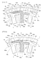
- FIG. 1 is a partial front view illustrating a state where a stator core is fitted to a motor case by shrinkage fitting
- FIG. 2 is a circumferential side view of the stator core
- FIG. 3 is a partly-omitted sectional view illustrating a lamination of the stator cores.
- a stator core 1 is formed of, for example, electromagnetic steel plate of magnetic material, and includes an annular circular yoke portion 3 and a plurality of tooth portions 5 protruding inwardly in a radial direction from an inner periphery of the yoke portion 3.
- An outer peripheral edge 3a of the yoke portion 3 is formed into a substantial circle, and an inner peripheries 3b and 3c are symmetrically in a circumferential direction between the tooth portions 5 and are linearly formed to intersect each other at an angle.
- a plurality of the stator cores 1 are laminated and the outer periphery of each yoke portion 3 in the laminated state is attached to the inner peripheral surface 7a of a motor case 7 as an annular member with an interference.
- This attaching is carried out by, for example, shrinkage fitting.
- the yoke portion 3 is attached to the motor case 7 with the radially-inward interference, and the outer peripheral edge 3a and the inner peripheral surface 7a contact with each other without a gap and have substantially the same curvature.
- the yoke portion 3 has displacement portions D and deformation portions T.
- the displacement portions D have been displaced by receiving radially-inward pressing force from the motor case 7.
- the deformation portions T have been deformed according to the displacement of the displacement portion D and keep on generating the tensile stress ⁇ 1 on the yoke portion 3. With this tensile stress ⁇ 1, tensile stress regions A through which magnetic flux passes between the yoke portion and the individual tooth portions 5 are formed.
- the generated tensile stress ⁇ 1 may counterbalance the compression stress ⁇ 2 generated by the pressing force from the motor case 7, to reduce or zero the compression stress.
- the stator core 1 is composed of a plurality of stator core divided bodies 9.
- Each stator core divided body 9 is a piece of the yoke portion 3 that is divided in the circumferential direction with division lines 11 spanning between the inner and outer peripheries.
- Each stator core divided body 9 is constructed with respect to each tooth portion 5 having a yoke component portion 9a.
- the individual stator core divided bodies 9 are annularly arranged so that division edges 11 a and 11 b at each division line 11 face each other in the circumferential direction.
- the yoke portion 3 has outer portions 13 and inner portions 15 in the radial direction through the divisions due to the division lines 11.
- Each outer portion 13 is arranged so as to protrude along one side in the circumferential direction of the yoke component portion 9a, and the inner portion 15 is arranged so as to protrude along the other side in the circumferential direction of the yoke component portion 9a on an internal diameter side relative to the outer portion 13.
- each outer portion 13 spans on an outer peripheral side of each yoke component portion 9a in the circumferential direction, and one side 13a of the outer portion 13 on one side in the circumferential direction of each tooth portion 5 is longer than the other side 13b of the same.
- a convex portion 17 is formed to protrude in the circumferential direction on a radial inner edge side.
- a concave portion 19 is formed in an interspace with respect to an external diameter side of the inner portion 15.
- a front end 13aa of the one side 13a of the individual outer portion 13 faces a front end 13ba of the other side 13b of the individual adjacent outer portion 13 without a gap so that each convex portion 17 is fitted to each concave portion 19 without a gap.
- This fitting of the concave and convex portions 19 and 17 at each interspace of the outer portions 13 constructs an engagement portion provided at each interspace of the stator core divided bodies 9, the engagement portion through which the deformation portion T of one stator core divided body 9 engages with the other stator core divided body 9 so as to cause the deformation.
- a radial inner edge 13c of each outer portion 13 and a radial outer edge 15a of each inner portion 15 face each other without a gap, and a front edge 15b of the individual inner portion 15 faces each tooth portion 15 in the circumferential direction without a gap.
- the division line 11 spans between the inner and outer peripheries of the yoke portion 3. Namely, the division line 11 at each interspace of the adjacent stator core divided bodies 9 spans from an interspace between the one side 13a and the other side 13b of the outer portions 13, through an interspace between the convex portion 17 and the concave portion 19 and an interspace between the radial inner edge 13c of the outer portion 13 and the radial outer edge 15a of the inner portion 15, to an interspace between the front edge 15b of the inner portion 15 and the tooth portion 5.
- a radial outer edge 13d of each outer portion 13 has been deformed along the inner peripheral surface 7a of the motor case 7 and has substantially the same curvature as the inner peripheral surface 7a. However, a slight gap may be formed between each interspace of the radial outer edges 13d and the inner peripheral surface 7a.
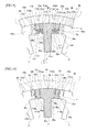
- FIG. 4 is a process chart illustrating a stator core manufacturing method
- FIG. 5 is a partial front view illustrating a stator core divided body processed by a divided body processing step
- FIG. 6 is a partial front view illustrating a joining state of stator core divided bodies before the shrinkage fitting, together with the motor case before shrinkage due to the shrinkage fitting.
- the stator core manufacturing method of the present invention has a divided body processing step S1 for manufacturing the stator core 1 of the motor and an assembling step S2.
- the divided body processing step S1 forms a plurality of stator core divided bodies 9... in the circumferential direction as illustrated in FIG. 5 that are divided by the division lines 11 illustrated in FIG. 1 .
- the yoke component portion 9a, the inner portion 15, and the outer portion 13 with the convex portion 17 and the concave portion 19 are formed to each stator core divided body 9 that is provided with the displacement portion D and the deformation portion T.
- each outer portion 13 before attaching to the motor case 7 is formed into an arc shape with a larger curvature than the inner peripheral surface 7a with a shrunk internal diameter due to the shrinkage fitting after the attaching.
- a linear edge portion 13ca on the convex portion 17 side and a linear edge portion 13cb on one side of each tooth portion 5 are formed to intersect each other.
- each inner portion 15 On the radial outer edge 15a of each inner portion 15, a linear edge portion 15aa on the concave portion 19 side and a linear edge portion 15ab on the front edge 15b side of each inner portion 15 are formed to intersect each other.
- the individual stator core divided bodies 9 are annularly arranged so that the division edges 11 a and 11 b face each other in the circumferential direction.
- each outer portion 13 of each annularly-joined stator core divided body 9 as the displacement portion D protrudes outwardly in the radial direction with respect to the internal diameter dimension of the inner peripheral surface 7a in FIG. 1 that is shrunk by shrinkage fitting in FIG. 1 after the attaching i.e. with respect to the outer dimension of the outer peripheral edge 3a of the yoke portion 3 after the attaching by shrinkage fitting.
- a gap is formed between each radial outer edge 13d and the inner peripheral surface 7aa before shrinkage due to the shrinkage fitting of the motor case 7.
- a gap is also formed between the front end 13aa of the one side 13a of the individual outer portion 13 and the front end 13ba of the other side 13b of each adjacent outer portion 13.
- each inner portion 15 has a gap with respect to one side of each tooth portion 5 and a gap is included also between the convex portion 17 and the concave portion 19, before the shrinkage due to the shrinkage fitting of the motor case 7.
- Each stator core divided body 9 annularly arranged in the circumferential direction is attached to the inner periphery of the motor case 7 by shrinkage fitting with the radially-inward interference, to become the state of FIG. 1 .
- each outer portion 13 receives the radially-inward pressing force from the motor case 7 and is inwardly displaced in the radial direction, the outer portion 13 deforms through the engagement of the concave and convex portions 19 and 17 as arrows to cause the deformation portion T to deform, and the radial outer edge 13d becomes a state where it follows the inner peripheral surface 7a after the shrinkage due to the shrinkage fitting.
- each stator core divided body 9 before the shrinkage fitting to the motor case 7 facing without a gap in the circumferential direction may be performed between the front edge 15b of each inner portion 15 and each tooth portion 5 and between the convex portion 17 and the concave portion 19 to perform the aforementioned assembling.
- the stator core 1 includes the annular yoke portion 3 and the tooth portions 5 protruding inwardly in the radial direction from the inner periphery of the yoke portion 3, wherein the outer peripheral edge 3a of the yoke portion 3 is attached to the inner peripheral surface 7a of the motor case 7.
- the yoke portion 3 includes the displacement portions D displaced by receiving the radially-inward pressing force from the motor case 7, and the deformation portions T deformed according to the displacements of the displacement portions D to generate the tensile stress ⁇ 1 so as to form the tensile stress regions A through which the magnetic flux passes between the tooth portions 5 and the yoke portion or so as to counterbalance the compression stress ⁇ 2 generated by the pressing force from the motor case 7.
- the displacement portions D which protrude outwardly in the radial direction before the yoke portion 3 is attached to the motor case 7 with respect to the internal diameter dimension of the inner peripheral surface 7a of the motor case 7 after the attaching, perform the displacements by attaching the yoke portion 3 to the annular member 7 with the interference.
- the yoke portion 3 with the deformations of the deformation portions T according to the displacements of the displacement portions D generates the tensile stress ⁇ 1 on the internal diameter side and forms with this tensile stress ⁇ 1 the tensile stress regions A through which the magnetic flux passes between the yoke portion and the individual tooth portions 5.
- the compression stress ⁇ 2 generated by the pressing force from the motor case 7 can also be counterbalanced, thereby to reduce or zero the compression stress.
- the magnetic flux can pass through the internal diameter side of the yoke portion 3 including the tensile stress regions A or through the entire yoke portion 3 with the compression stress ⁇ 2 that is reduced or zeroed, thereby to reduce the magnetic loss such as iron loss. Accordingly, it allows the magnetic flux to efficiently pass to further improve the output efficiency of the motor.
- stator core divided bodies 9 divided in the circumferential direction with the divisions at the division lines 11 spanning between the inner and outer peripheries at the yoke portion 3 and having tooth portions 5 and yoke component portions 9a, annularly arranges each stator core divided body 9 so that the division edges 11 a and 11 b due to each division face each other in the circumferential direction, and provides at each interspace between the stator core divided bodies 9 the engagement portion 17 and 19 through which the deformation portion T of one stator core divided body 9 engages with the other stator core divided body 9 so as to cause the deformation.
- the stator core 1 can be composed of the individual stator core divided bodies 9, can surely cause the deformation by the individual concave and convex portions 17 and 19 at each annularly-arranged stator core divided body 9 to be surely fixed to the motor case 7, and provides the aforementioned effects.
- the yoke portion 3 has the outer portion 13 and the inner portion 15 in the radial direction that are formed in the circumferential direction by the individual divisions.
- the outer portion 13 is arranged so as to protrude along the one side in the circumferential direction of the yoke component portion 9a.
- the inner portion 15 is arranged so as to protrude along the other side in the circumferential direction of the yoke component portion 9a on the internal diameter side relative to the outer portion 13.
- the radial outer edge 13d side of the outer portion 13 outwardly protrudes in the radial direction as the displacement portion D before the yoke portion 3 is attached to the motor case 7.
- the radial inner edge 13c side of the outer portion 13 has the gap with respect to the radial outer edge 15a of the inner portion 15 as the deformation portion T before the yoke portion 3 is attached to the motor case 7.
- the deformation of the deformation portion T and the displacement of the displacement portion D are performed by attaching the yoke portion 3 to the motor case 7 with the interference due to the shrinkage fitting.
- the displacement portion D of the outer portion 13 receives the radially-inward pressing force due to the attaching to the motor case 7 by the shrinkage fitting, so that the deformation portion T is deformed.
- the tensile stress ⁇ 1 is generated on the radial inner edge 13c side in each outer portion 13, thereby to form with this tensile stress ⁇ 1 the tensile stress region A through which the magnetic flux passes between the yoke portion and each tooth portion 5.
- the compression stress ⁇ 2 generated on the radial outer edge 13d side of each outer portion 13 by the pressing force from the motor case 7 can also be counterbalanced, thereby to reduce or zero the compression stress.
- each outer portion 13 When assembling each outer portion 13 from the curved protrusion state of FIG. 6 to the state of FIG. 1 , the radial outer edge 13d of each outer portion 13 frictionally engages with and is surely fixed to the inner peripheral surface 7a of the motor case 7. With this fixation due to the frictional engagement, the interference according to the shrinkage fitting to the motor case 7 may be reduced and the compression stress ⁇ 2 acting on the outer portion 13 may be also reduced.
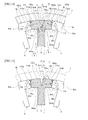
- FIGs. 7 and 8 relate to Embodiment 2 of the present invention in which FIG. 7 is a partial front view illustrating a state where a stator core is fitted to a motor case by shrinkage fitting and FIG. 8 is a partial front view illustrating a joining state of stator core divided bodies before the shrinkage fitting together with the motor case before shrinkage due to the shrinkage fitting.
- a basic structure is the same as that of Embodiment 1, the same components are represented with the same reference numerals and corresponding components are represented with the same reference numerals with A to avoid repetition in a description.
- a stator core 1A of this embodiment also has respective outer portions 13A and inner portions 15A.
- the outer portion 13A is integrally arranged so as to protrude on one side in a circumferential direction of a yoke component portion 9Aa on an external diameter side of each tooth portion 5.
- the inner portion 15A is integrally arranged so as to protrude on the other side in the circumferential direction of the yoke component portion 9Aa.
- inclined faces 13Aaa and 13Aba construct an engagement portion.
- the inclined face 13Aaa is formed at a front end of the outer portion 13A
- the inclined face 13Aba is formed at a base end of the outer portion 13A.
- a radial inner edge 13Ac of each outer portion 13A and a radial outer edge 15Aa of each inner portion 15 face each other without a gap
- a front edge 15Ab of each inner portion 15A faces each tooth portion 5 without a gap.
- a division line 11A spans between inner and outer peripheries of a yoke portion 3A.
- the division line 11A includes division edges 11Aa and 11Ab spanning from the inclined faces 13Aaa and 13Aba at each interspace between the outer portions 13A, through an interspace between the radial inner edge 13Ac of each outer portion 13A and the radial outer edge 15Aa of each inner portion 15A, to an interspace between the front edge 15Ab of each inner portion 15A and each tooth portion 5.
- a radial outer edge 13Ad of each outer portion 13 is continuous in a circle along an inner peripheral surface 7a of the motor case 7 and has substantially the same curvature as the inner peripheral surface 7a.
- each stator core divided body 9A When manufacturing, in a divided body processing step S1, the stator core divided bodies 9A that are provided with the displacement portions D and the deformation portions T, and in an assembling step S2, each stator core divided body 9A is annularly arranged so that individual division edges 11Aa and 11Ab face each other in the circumferential direction as illustrated in FIG. 8 .
- a gap is formed between the radial outer edge 13Ad and the inner peripheral surface 7aa before shrinkage due to the shrinkage fitting of the motor case as illustrated in FIG. 8 .
- the radial inner edge 13Ac of each outer portion 13A before shrinkage as a part of the deformation portion T due to the shrinkage fitting of the yoke portion 3A to the motor case 7 forms a gap in an interspace with respect to the radial outer edge 15Aa of each inner portion 15A.
- This gap is set by, for example, making the curvature of the radial inner edge 13Ac slightly larger than the curvature of the radial outer edge 15Aa.
- each inner portion 15A has a gap with respect to one side of each tooth portion 5 before attaching to the motor case 7 by shrinkage fitting.
- Each stator core divided body 9A annularly arranged in the circumferential direction is attached to the inner peripheral surface 7a of the motor case 7 by shrinkage fitting with a radially-inward interference, to become the state of FIG. 7 .
- each outer portion 13A receives the radially-inward pressing force from the motor case 7 and is displaced inwardly in the radial direction, and becomes a state where the radial outer edge 13Ad follows the inner peripheral surface 7a while causing the deformation portion T to deform by relative deviation due to the engagement of the inclined faces 13Aaa and 13Aba and the thrust P A along the inclination.
- each stator core divided body 9A before the attaching to the motor case 7 facing without a gap in the circumferential direction may be performed between the front edge 15Ab of each inner portion 15A and each tooth portion 5 to perform the aforementioned assembling.
- each stator core divided body 9A can be stably annularly assembled.
- Each outer portion 13A with the deformation of the deformation portion T according to the displacement of the displacement portion D generates the tensile stress ⁇ 1 on the radial inner edge 13Ac side, and the tensile stress ⁇ 1 forms the tensile stress region A through which the magnetic flux passes between each outer portion and each tooth portion.
- the compression stress ⁇ 2 generated on the radial outer edge 13Ad side of each outer portion 13A by the pressing force from the motor case 7 is counterbalanced, thereby to reduce or zero the compression stress.
- a slight gap may be formed between the radial inner edge 13Ac of each outer portion 13A and the radial outer edge 15Aa of each inner portion 15A. This gap is along a direction in which the magnetic flux passes and has no influence.
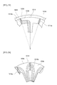
- FIGs. 9 and 10 relate to Embodiment 3 of the present invention in which FIG. 9 is a partial front view illustrating a state where a stator core is fitted to a motor case by shrinkage fitting and FIG. 10 is a partial front view illustrating a joining state of stator core divided bodies before the shrinkage fitting.
- a basic structure is the same as that of Embodiment 1, the same components are represented with the same reference numerals and corresponding components are represented with the same reference numerals with B to avoid repetition in a description.
- a stator core 1 B of this embodiment is also composed of a plurality of stator core divided bodies 9B having displacement portions D and deformation portions T.
- Each stator core divided body 9B is a piece of the yoke portion 3B that is divided in a circumferential direction with division lines 11 B spanning between inner and outer peripheries.
- an outer peripheral edge 3Ba of the yoke portion 3B has the same curvature as an inner peripheral surface 7a of the motor case 7, and on the radial inner edge inner peripheral edges 3Bb and 3Bc are formed on both sides in the circumferential direction of each stator core divided body 9B.
- Each stator core divided body 9B is constructed with respect to each tooth portion 5 having a yoke component portion 9Ba.
- Each stator core divided body 9B is annularly arranged so that division edges 11Ba and 11Bb at each division line 11 B face each other without a gap in the circumferential direction.
- Each stator core divided body 9B is provided with a pair of slits 21 a and 21 b having no gap and rotatable portions 23a and 23b between the slits 21 a and 21 b and respective adjacent yoke component portions 9Ba.
- Each slit 21 a, 21 b is formed from a radial outer edge 13Bd to a middle portion in a radial direction. At an inner end portion of each slit 21 a, 21 b, a hole 21aa, 21ba is formed. On the inner peripheral edges 3Bb and 3Bc on both sides in the circumferential direction of each stator core divided body 9B, semicircle portions 25a and 25b are formed corresponding to the holes 21aa and 21ba in the radial direction. Between the holes 21aa and 21ba and the semicircle portions 25a and 25b, the deformation portions T are constructed.
- concave and convex portions 17B and 19B formed in each interspace of the circumferentially-facing rotatable portion 23a and 23b construct an engagement portion.
- each stator core divided body 9B is annularly arranged so that individual division edges 11Ba and 11Bb face each other in the circumferential direction as illustrated in FIG. 10 .
- each yoke component portion 9Ba of each annularly-joined stator core divided body 9B causes the central portion side between the slits 21 a and 21 b of a part of the radial outer edge 13Bb as the displacement portion D to protrude outwardly in the radial direction with respect to the internal diameter dimension of the inner peripheral surface 7a that is shrunk due to the shrinkage fitting after the assembling in FIG. 9 i.e. with respect to the outer dimension of an outer peripheral edge 3Ba of the yoke portion 3B after the attaching by shrinkage fitting.
- the slits 21 a and 21 b open in the circumferential direction and the rotatable portions 23a and 23b are in a before-rotation state that forms gaps between adjacent rotatable portions 23b and 23a corresponding to the slits 21 a and 21 b according to the open state of the slits 21 a and 21 b.
- the radially-inward pressing force from the motor case 7 acts to displace the displacement portion D through the slits 21 a and 21 b, and the rotatable portions 23b and 23a are rotated so as to close the slits 21 a and 21 b and the gaps, thereby to deform the deformation portions T.
- each yoke component portion 9Ba frictionally engages with the inner peripheral surface 7a of the motor case 7 as illustrated in FIG. 9 , thereby to annularly stably assemble each stator core divided body 9B.
- the tensile stress ⁇ 1 is generated and the tensile stress ⁇ 1 forms tensile stress regions A through which the magnetic flux passes between the yoke portion and each tooth portion 5.
- the compression stress ⁇ 2 generated by the pressing force from the motor case 7 is counterbalanced, thereby to reduce or zero the compression stress.
- FIGs. 11 and 12 relate to Embodiment 4 of the present invention in which FIG. 11 is a partial front view illustrating a state where a stator core is fitted to a motor case by shrinkage fitting and FIG. 12 is a partial front view illustrating a joining state of stator core divided bodies before the shrinkage fitting.
- a basic structure is the same as that of Embodiment 3, the same components are represented with the same reference numerals and corresponding components are represented with the same reference numerals with C instead of B to avoid repetition in a description.
- a single slit 21C is formed at the center of each yoke component portion 9Ca of each stator core divided body 9C.
- Semicircle portions 25Ca and 25Cb constructing deformation portions T at intermediates with respect to the hole 21 Ca are provided at corners between each yoke component portion 9Ca and each tooth portion 5.
- both sides of the slit 21C are configured as rotatable portions 23Ca and 23Cb and the slit 21C sides on the rotatable portions 23Ca and 23Cb are configured as displacement portions D.
- each yoke component portion 9Ca of each annularly-joined stator core divided body 9C causes the slit 23C sides on the rotatable portions 23Ca and 23Cb as the displacement portions D to protrude outwardly in the radial direction with respect to the internal diameter dimension of the inner peripheral surface 7a that is shrunk due to the shrinkage fitting after the assembling in FIG. 11 i.e. with respect to the outer dimension of an outer peripheral edge 3Ca of the yoke portion 3C after the attaching by shrinkage fitting.
- the slit 21C open in the circumferential direction and the rotatable portions 23Ca and 23Cb are in a before-rotation state that forms gaps corresponding to the slit 21C in interspaces relative to adjacent rotatable portions 23Cb and 23Ca according to the open state of the slit 21C.
- the radially-inward pressing force from the motor case 7 acts to displace the displacement portions D through the slit 21C, and the rotatable portions 23Cb and 23Ca are rotated so as to close the slit 21C and the gaps, thereby to deform the deformation portions T.
- each yoke component portion 9Ca frictionally engages with the inner peripheral surface 7a of the motor case 7 as illustrated in FIG. 11 , thereby to annularly stably assemble each stator core divided body 9C.
- the tensile stress ⁇ 1 is generated and the tensile stress ⁇ 1 forms tensile stress regions A through which the magnetic flux passes between the yoke portion and each tooth portion 5.
- the compression stress ⁇ 2 generated by the pressing force from the motor case 7 is counterbalanced, thereby to reduce or zero the compression stress.
- FIGs. 13 to 16 relate to Embodiment 5 of the present invention in which FIG. 13 is a partial front view of stator core, FIG. 14 is a process chart illustrating a stator core manufacturing method, FIG. 15 is a partial front view illustrating the stator core before attaching, and FIG. 16 is a partial front view illustrating the stator core before the shrinkage fitting, together with the motor case before shrinkage due to the shrinkage fitting.
- a basic structure is the same as that of Embodiment 1, the same components are represented with the same reference numerals and corresponding components are represented with the same reference numerals with D to avoid repetition in a description.
- a stator core 1 D of this Embodiment 5 has a yoke portion 3D that is a ring shape continuous in a circumferential direction.
- This embodiment has no concave and convex portions 19 and 17 as the engagement portion of Embodiment 1 and has an inner portion 15D that is formed into a ring shape being continuous in the circumferential direction.
- a stator core manufacturing method of this embodiment has a core processing step S10 for manufacturing the stator core 1 D and an assembling step S11.
- stator core 1 D illustrated in FIG. 15 is formed.
- the stator core 1 D has outer portions 13D, the inner portion 15D, the yoke portion 3D and tooth portions 5D, a radial outer edge 13Dd side of each outer portion 13D protrudes outwardly in a radial direction.
- each outer portion 13D of the stator core 1 D protrudes outwardly in the radial direction with respect to the internal diameter dimension of an inner peripheral surface 7a that is shrunk due to shrinkage fitting after assembling in FIG. 13 i.e. with respect to the outer dimension of an outer peripheral edge 3Da of the yoke portion 3D after attaching by shrinkage fitting.
- the stator cores 1 Da of FIG. 15 are laminated in a thickness direction and arranged on an inner periphery of the motor case 7 as illustrated in FIG. 16 .
- the inner portion 15D and the tooth portions 5D are integrated with each other, no gap is formed therebetween, and other gaps in the other parts are the same as those of Embodiment 1.
- the stator core 1 D arranged on the inner periphery of the motor case 7 is attached by shrinkage fitting with a radially-inward interference, and becomes the state of FIG. 13 .
- the tensile stress ⁇ 1 is generated on a radial inner edge 13Dc side and the tensile stress ⁇ 1 forms the tensile stress region A through which the magnetic flux passes between the yoke portion and each tooth portion 5.
- the compression stress ⁇ 2 generated by the pressing force from the motor case 7 on the radial outer edge 13Dd side of each outer portion 13D is counterbalanced, thereby to reduce or zero the compression stress.
- this embodiment also provides the same effects as Embodiment 1.
- stator core 1 Da is not divided, it is easy to be handled, reduces the number of components, and facilitates the assembly work and parts management.
- a slight gap may be formed between the radial inner edge 13Dc of each outer portion 13D and the radial outer edge 15Da of each inner portion 15D after the assembling. This gap is along a direction in which the magnetic flux passes and has no influence.
- FIGs. 17 and 18 relate to Embodiment 6 of the present invention in which FIG. 17 is a partial front view illustrating a stator core before shrinkage fitting together with a motor case before shrinkage due to the shrinkage fitting, FIG. 18 is a partial front view illustrating a state where the stator core is fitted to the motor case by shrinkage fitting.
- a basic structure is the same as that of Embodiment 5, the same components are represented with the same reference numerals and corresponding components are represented with the same reference numerals with E instead of D to avoid repetition in a description.
- a stator core 1 E of this Embodiment 6 has a yoke portion 3E that is formed into a ring shape being continuous in a circumferential direction.
- the yoke portion 3E of this embodiment makes a circumferential length of an outer portion 13E longer than that of Embodiment 5.
- a front end 13Eaa of one side 13Ea in the circumferential direction of each outer portion 13E strongly contacts with a front end 13Eba on the other side 13Eb in the circumferential direction of each adjacent outer portion 13E, so that a thrust is generated on the contacting faces and compression stress is generated on each outer portion 13E in the circumferential direction simultaneously.
Landscapes
- Engineering & Computer Science (AREA)
- Power Engineering (AREA)
- Manufacturing & Machinery (AREA)
- Iron Core Of Rotating Electric Machines (AREA)
- Manufacture Of Motors, Generators (AREA)
Abstract
Description
- The present invention relates to a stator core for a motor and a manufacturing method therefor.
- Conventionally, there are ones disclosed in
Patent documents FIGs. 19 to 24 . -
FIG. 19 is a partial front view illustrating a state where a stator core is fitted to a core case by shrinkage fitting,FIG. 20 is a partial front view of the stator core,FIG. 21 is a partial front view illustrating a state where a stator core is fitted to a core case by shrinkage fitting,FIG. 22 is a sectional view illustrating the state where the stator core is fitted to the core case by shrinkage fitting. - In any
FIGs. 19 to 24 , stator core dividedbodies stator core core case - Where, at the time of the shrinkage fitting, there is a problem of increasing iron loss due to compression stress generated on each stator core divided
body - Against this problem, in the
stator core 101A ofFIGs. 19 and 20 , slits 101Aa are formed so as not to generate the compression stress. In thestator core FIGs. 21 or 22 , holes 103Ba or 103Ca are formed so as to reduce the compression stress. - However, there is a problem that the slits 101Aa or holes 103Ba or 103Ca introduce the increase in magnetic resistance thereat to deteriorate the magnetic characteristics.
- On the other hand, there is an example for one reducing pressing force received by a stator core without slits or holes as illustrated in
FIGs. 23 and 24 disclosed in Patent document 4.FIG. 23 is a partial front view illustrating a stress generating state in a state where a stator core is fitted to a core case by shrinkage fitting, andFIG. 24 is a partial front view illustrating a magnetic flux formation state in the state where the stator core is fitted to the core case by shrinkage fitting. - In
FIGs. 23 and 24 , ayoke portion 101 Da included in astator core 101 D has a radial thickness "a" is formed less than a radial thickness "b" of acore case 105D. - With these setting of the thicknesses "a" and "b", tensile stress is generated on the
core case 105D as illustrated inFIG. 23 to pass magnetic flux through thecore case 105D. - However, large compression stress is caused to act on the
yoke portion 101 Da closer totooth portions 107D, and there is a drawback in reducing magnetic resistance at theyoke portion 101 Da existing between thetooth portions 107D and thecore case 105D. -
- PATENT DOCUMENT 1:
JP2005-51941A - PATENT DOCUMENT 2:
JP2009-261162A - PATENT DOCUMENT 3:
JP2002-136013A - PATENT DOCUMENT 4:
JP2011-125180A - A problem to be solved is that the reduction of the compression stress by means of the slits or holes causes the increase in magnetic resistance to deteriorate the magnetic characteristics whereas the setting of the thicknesses of the annular member and yoke portion involves the drawback in reducing the magnetic resistance.
- The present invention provides a stator core for a motor in order to further improve the magnetic characteristics. The stator core includes an annular yoke portion and tooth portions protruding inwardly in a radial direction from an inner periphery of the yoke portion, wherein an outer peripheral edge of the yoke portion is attached to an inner peripheral surface of an annular member. The yoke portion includes displacement portions displaced by receiving radially-inward pressing force from the annular member, and deformation portions deformed according to displacements of the displacement portions to generate tensile stress so as to form tensile stress regions through which magnetic flux passes between the tooth portions and the yoke portion or so as to counterbalance compression stress generated by the pressing force from the annular member. The displacement portions, which outwardly protrude in the radial direction before the yoke portion is attached to the annular member with respect to an internal diameter dimension of the inner peripheral surface of the annular member after the attaching, perform the displacements by attaching the yoke portion to the annular member with an interference.
- The present invention provides a stator core manufacturing method for manufacturing the aforementioned stator core for a motor. The method includes a divided body processing step processing a plurality of stator core divided bodies having the displacement portions and the deformation portions, and an assembling step annularly arranging the plurality of stator core divided bodies so that division edges face each other in the circumferential direction, respectively and attaching the stator core bodies to the inner peripheral surface of the annular member with a radially-inward interference, thereby to conduct the deformations of the deformation portions due to the displacements of the displacement portions.
- The present invention provides a stator core manufacturing method for manufacturing the aforementioned stator core for a motor. The method includes a core processing step forming a ring-shaped stator core having the displacement portions and the deformation portions before the attaching to the annular member, and an assembling step attaching the stator core to an inner periphery of the annular member with a radially-inward interference, thereby to conduct the deformations of the deformation portions due to the displacements of the displacement portions.
- The stator core for a motor of the present invention, due to the aforementioned configuration, can generate the tensile stress by the deformation portions deformed according to the displacements of the displacement portions displaced by receiving the radially-inward pressing force from the annular member. With this tensile stress, the tensile stress regions through which the magnetic flux passes between the tooth portions and the yoke portion can be formed on the yoke portion or the compression stress generated on the yoke portion by the pressing force from the annular member can be counterbalanced.
- Accordingly, the magnetic resistance of the yoke portion can be reduced with the tensile stress portions of the yoke portion of the stator core, or the compression stress on the yoke portion can be reduced or zeroed to reduce the magnetic resistance.
- Therefore, many of the magnetic flux can pass through the tensile stress regions on the yoke portion or through the entire yoke portion with zero compression stress, thereby to reduce the magnetic loss such as iron loss.
- The stator core manufacturing method of the present invention, due to the aforementioned configuration, manufactures the plurality of stator core divided bodies, annularly joins the plurality of stator core divided bodies together in the circumferential direction, and attaches them to the inner periphery of the annular member with the radially-inward interference, thereby to form the tensile stress regions or reduce or zero the compression stress.
- The stator core manufacturing method of the present invention, due to the aforementioned configuration, manufactures a semi-finished stator core and attaches the semi-finished stator core to the inner periphery of the annular member with the radially-inward interference, thereby to form the tensile stress regions or reduce or zero the compression stress.
-
- [
FIG. 1 ] It is a partial front view illustrating a state where a stator core is fitted to a motor case by shrinkage fitting. (Embodiment 1) - [
FIG. 2 ] It is a circumferential side view of the stator core. (Embodiment 1) - [
FIG. 3 ] It is a sectional view illustrating a lamination of the stator cores.
(Embodiment 1) - [
FIG. 4 ] It is a process chart illustrating a stator core manufacturing method.
(Embodiment 1) - [
FIG. 5 ] It is a partial front view illustrating a stator core divided body processed by a divided body processing step. (Embodiment 1) - [
FIG. 6 ] It is a partial front view illustrating a joining state of stator core divided bodies before the shrinkage fitting, together with the motor case before shrinkage due to the shrinkage fitting. (Embodiment 1) - [
FIG. 7 ] It is a partial front view illustrating a state where a stator core is fitted to a motor case by shrinkage fitting. (Embodiment 2) - [
FIG. 8 ] It is a partial front view illustrating a joining state of stator core divided bodies before the shrinkage fitting, together with the motor case before shrinkage due to the shrinkage fitting. (Embodiment 2) - [
FIG. 9 ] It is a partial front view illustrating a state where a stator core is fitted to a motor case by shrinkage fitting. (Embodiment 3) - [
FIG. 10 ] It is a partial front view illustrating a joining state of stator core divided bodies before the shrinkage fitting. (Embodiment 3) - [
FIG. 11 ] It is a partial front view illustrating a state where a stator core is fitted to a motor case by shrinkage fitting. (Embodiment 4) - [
FIG. 12 ] It is a partial front view illustrating a joining state of stator core divided bodies before the shrinkage fitting. (Embodiment 4) - [
FIG. 13 ] It is a partial front view illustrating a state where a stator core is fitted to a motor case by shrinkage fitting. (Embodiment 5) - [
FIG. 14 ] It is a process chart illustrating a stator core manufacturing method.
(Embodiment 5) - [
FIG. 15 ] It is a partial front view illustrating a state of the stator core before the shrinkage fitting. (Embodiment 5) - [
FIG. 16 ] It is a partial front view illustrating the stator core before the shrinkage fitting, together with the motor case before shrinkage due to the shrinkage fitting.
(Embodiment 5) - [
FIG. 17 ] It is a partial front view illustrating a stator core before shrinkage fitting, together with a motor case before shrinkage due to the shrinkage fitting.
(Embodiment 6) - [
FIG. 18 ] It is a partial front view illustrating a state where the stator core is fitted to the motor case by shrinkage fitting. (Embodiment 6) - [
FIG. 19 ] It is a partial front view illustrating a state where a stator core is fitted to a motor case by shrinkage fitting. (Related art) - [
FIG. 20 ] It is a partial front view of the stator core. (Related art) - [
FIG. 21 ] It is a partial front view illustrating a state where a stator core is fitted to a core case by shrinkage fitting. (Related art) - [
FIG. 22 ] It is a sectional view illustrating the state where the stator core is fitted to the core case by shrinkage fitting. (Related art) - [
FIG. 23 ] It is a partial front view illustrating a stress generating state in a state where a stator core is fitted to a core case by shrinkage fitting. (Related art) - [
FIG. 24 ] It is a partial front view illustrating a magnetic flux formation state in the state where the stator core is fitted to the core case by shrinkage fitting. (Related art) - The object that is to further improve the magnetic characteristics is accomplished by a
stator core 1. Thestator core 1 includes anannular yoke portion 3 andtooth portions 5 protruding inwardly in a radial direction from an inner periphery of theyoke portion 3, wherein an outerperipheral edge 3a of theyoke portion 3 is attached to an innerperipheral surface 7a of anannular member 7. Theyoke portion 3 includes displacement portions D displaced by receiving radially-inward pressing force from theannular member 7, and deformation portions T deformed according to displacements of the displacement portions D to generate tensile stress σ1 so as to form tensile stress regions A through which magnetic flux passes between thetooth portion 5 and the yoke portion or so as to counterbalance compression stress σ2 generated by the pressing force from theannular member 7. The displacement portions D, which outwardly protrude in the radial direction before theyoke portion 3 is attached to theannular member 7 with respect to the internal diameter dimension of the innerperipheral surface 7a of theannular member 7 after the attaching, perform the displacements by attaching theyoke portion 3 to theannular member 7 with an interference. -
FIG. 1 is a partial front view illustrating a state where a stator core is fitted to a motor case by shrinkage fitting,FIG. 2 is a circumferential side view of the stator core, andFIG. 3 is a partly-omitted sectional view illustrating a lamination of the stator cores. - As illustrated in
FIGs. 1 to 3 , astator core 1 is formed of, for example, electromagnetic steel plate of magnetic material, and includes an annularcircular yoke portion 3 and a plurality oftooth portions 5 protruding inwardly in a radial direction from an inner periphery of theyoke portion 3. An outerperipheral edge 3a of theyoke portion 3 is formed into a substantial circle, and aninner peripheries tooth portions 5 and are linearly formed to intersect each other at an angle. - A plurality of the
stator cores 1 are laminated and the outer periphery of eachyoke portion 3 in the laminated state is attached to the innerperipheral surface 7a of amotor case 7 as an annular member with an interference. This attaching is carried out by, for example, shrinkage fitting. Theyoke portion 3 is attached to themotor case 7 with the radially-inward interference, and the outerperipheral edge 3a and the innerperipheral surface 7a contact with each other without a gap and have substantially the same curvature. - The
yoke portion 3 has displacement portions D and deformation portions T. - The displacement portions D have been displaced by receiving radially-inward pressing force from the
motor case 7. - The deformation portions T have been deformed according to the displacement of the displacement portion D and keep on generating the tensile stress σ1 on the
yoke portion 3. With this tensile stress σ1, tensile stress regions A through which magnetic flux passes between the yoke portion and theindividual tooth portions 5 are formed. The generated tensile stress σ1 may counterbalance the compression stress σ2 generated by the pressing force from themotor case 7, to reduce or zero the compression stress. - The
stator core 1 is composed of a plurality of stator core dividedbodies 9. Each stator core dividedbody 9 is a piece of theyoke portion 3 that is divided in the circumferential direction withdivision lines 11 spanning between the inner and outer peripheries. - Each stator core divided
body 9 is constructed with respect to eachtooth portion 5 having ayoke component portion 9a. The individual stator core dividedbodies 9 are annularly arranged so that division edges 11 a and 11 b at eachdivision line 11 face each other in the circumferential direction. - The
yoke portion 3 hasouter portions 13 andinner portions 15 in the radial direction through the divisions due to the division lines 11. - Each
outer portion 13 is arranged so as to protrude along one side in the circumferential direction of theyoke component portion 9a, and theinner portion 15 is arranged so as to protrude along the other side in the circumferential direction of theyoke component portion 9a on an internal diameter side relative to theouter portion 13. - According to this embodiment, each
outer portion 13 spans on an outer peripheral side of eachyoke component portion 9a in the circumferential direction, and oneside 13a of theouter portion 13 on one side in the circumferential direction of eachtooth portion 5 is longer than theother side 13b of the same. - At the one
side 13a of eachouter portion 13, aconvex portion 17 is formed to protrude in the circumferential direction on a radial inner edge side. At an internal diameter side of theother side 13b of eachouter portion 13, aconcave portion 19 is formed in an interspace with respect to an external diameter side of theinner portion 15. - A front end 13aa of the one
side 13a of the individualouter portion 13 faces a front end 13ba of theother side 13b of the individual adjacentouter portion 13 without a gap so that eachconvex portion 17 is fitted to eachconcave portion 19 without a gap. This fitting of the concave andconvex portions outer portions 13 constructs an engagement portion provided at each interspace of the stator core dividedbodies 9, the engagement portion through which the deformation portion T of one stator core dividedbody 9 engages with the other stator core dividedbody 9 so as to cause the deformation. - A radial
inner edge 13c of eachouter portion 13 and a radialouter edge 15a of eachinner portion 15 face each other without a gap, and afront edge 15b of the individualinner portion 15 faces eachtooth portion 15 in the circumferential direction without a gap. - The
division line 11 spans between the inner and outer peripheries of theyoke portion 3. Namely, thedivision line 11 at each interspace of the adjacent stator core dividedbodies 9 spans from an interspace between the oneside 13a and theother side 13b of theouter portions 13, through an interspace between theconvex portion 17 and theconcave portion 19 and an interspace between the radialinner edge 13c of theouter portion 13 and the radialouter edge 15a of theinner portion 15, to an interspace between thefront edge 15b of theinner portion 15 and thetooth portion 5. - A radial
outer edge 13d of eachouter portion 13 has been deformed along the innerperipheral surface 7a of themotor case 7 and has substantially the same curvature as the innerperipheral surface 7a. However, a slight gap may be formed between each interspace of the radialouter edges 13d and the innerperipheral surface 7a. -
FIG. 4 is a process chart illustrating a stator core manufacturing method,FIG. 5 is a partial front view illustrating a stator core divided body processed by a divided body processing step, andFIG. 6 is a partial front view illustrating a joining state of stator core divided bodies before the shrinkage fitting, together with the motor case before shrinkage due to the shrinkage fitting. - As illustrated in
FIG. 4 , the stator core manufacturing method of the present invention has a divided body processing step S1 for manufacturing thestator core 1 of the motor and an assembling step S2. - The divided body processing step S1 forms a plurality of stator core divided
bodies 9... in the circumferential direction as illustrated inFIG. 5 that are divided by the division lines 11 illustrated inFIG. 1 . - The
yoke component portion 9a, theinner portion 15, and theouter portion 13 with theconvex portion 17 and theconcave portion 19 are formed to each stator core dividedbody 9 that is provided with the displacement portion D and the deformation portion T. - The radial
outer edge 13d of eachouter portion 13 before attaching to themotor case 7 is formed into an arc shape with a larger curvature than the innerperipheral surface 7a with a shrunk internal diameter due to the shrinkage fitting after the attaching. On the radialinner edge 13c of eachouter portion 13, a linear edge portion 13ca on theconvex portion 17 side and a linear edge portion 13cb on one side of eachtooth portion 5 are formed to intersect each other. - On the radial
outer edge 15a of eachinner portion 15, a linear edge portion 15aa on theconcave portion 19 side and a linear edge portion 15ab on thefront edge 15b side of eachinner portion 15 are formed to intersect each other. - On the radial
inner edge 15c of eachinner portion 15, innerperipheral edges yoke portion 3 are formed. - In the assembling step S2, as illustrated in
FIG. 6 , the individual stator core dividedbodies 9 are annularly arranged so that the division edges 11 a and 11 b face each other in the circumferential direction. - Before attaching to the
motor case 7 by shrinkage fitting, the radialouter edge 13d side of eachouter portion 13 of each annularly-joined stator core dividedbody 9 as the displacement portion D protrudes outwardly in the radial direction with respect to the internal diameter dimension of the innerperipheral surface 7a inFIG. 1 that is shrunk by shrinkage fitting inFIG. 1 after the attaching i.e. with respect to the outer dimension of the outerperipheral edge 3a of theyoke portion 3 after the attaching by shrinkage fitting. With this protrusion, a gap is formed between each radialouter edge 13d and the inner peripheral surface 7aa before shrinkage due to the shrinkage fitting of themotor case 7. - A gap is also formed between the front end 13aa of the one
side 13a of the individualouter portion 13 and the front end 13ba of theother side 13b of each adjacentouter portion 13. - The linear edge portion 13cb of the radial
inner edge 13c of eachouter portion 13, before the shrinkage due to the shrinkage fitting of themotor case 7 to which theyoke portion 3 is fixed, forms a gap with respect to the linear edge portion 15ab of the radialouter edge 15a of eachinner portion 15. - The
front edge 15b of eachinner portion 15 has a gap with respect to one side of eachtooth portion 5 and a gap is included also between theconvex portion 17 and theconcave portion 19, before the shrinkage due to the shrinkage fitting of themotor case 7. - Each stator core divided
body 9 annularly arranged in the circumferential direction is attached to the inner periphery of themotor case 7 by shrinkage fitting with the radially-inward interference, to become the state ofFIG. 1 . - Namely, the displacement portion D of each
outer portion 13 receives the radially-inward pressing force from themotor case 7 and is inwardly displaced in the radial direction, theouter portion 13 deforms through the engagement of the concave andconvex portions outer edge 13d becomes a state where it follows the innerperipheral surface 7a after the shrinkage due to the shrinkage fitting. - In this state, the gap between the radial
outer edge 13d and the innerperipheral surface 7a and the gap between the linear edge portion 13cb and the linear edge portion 15ab are absorbed. - With the displacement of the displacement portion D, the gap between the
front edge 15b of eachinner portion 15 and eachtooth portion 5 and the gap between the convex andconcave portions - Incidentally, when annularly arranging each stator core divided
body 9 before the shrinkage fitting to themotor case 7, facing without a gap in the circumferential direction may be performed between thefront edge 15b of eachinner portion 15 and eachtooth portion 5 and between theconvex portion 17 and theconcave portion 19 to perform the aforementioned assembling. - When the deformation portion T is deformed according to the displacement of the displacement portion D of the
outer portion 13, the radialouter edge 13d of theouter portion 13 frictionally engages with the innerperipheral surface 7a. - In
Embodiment 1 of the present invention, thestator core 1 includes theannular yoke portion 3 and thetooth portions 5 protruding inwardly in the radial direction from the inner periphery of theyoke portion 3, wherein the outerperipheral edge 3a of theyoke portion 3 is attached to the innerperipheral surface 7a of themotor case 7. Theyoke portion 3 includes the displacement portions D displaced by receiving the radially-inward pressing force from themotor case 7, and the deformation portions T deformed according to the displacements of the displacement portions D to generate the tensile stress σ1 so as to form the tensile stress regions A through which the magnetic flux passes between thetooth portions 5 and the yoke portion or so as to counterbalance the compression stress σ2 generated by the pressing force from themotor case 7. The displacement portions D, which protrude outwardly in the radial direction before theyoke portion 3 is attached to themotor case 7 with respect to the internal diameter dimension of the innerperipheral surface 7a of themotor case 7 after the attaching, perform the displacements by attaching theyoke portion 3 to theannular member 7 with the interference. - As stated above, as illustrated in
FIG. 1 , theyoke portion 3 with the deformations of the deformation portions T according to the displacements of the displacement portions D generates the tensile stress σ1 on the internal diameter side and forms with this tensile stress σ1 the tensile stress regions A through which the magnetic flux passes between the yoke portion and theindividual tooth portions 5. - Further, with the generated tensile stress σ1, the compression stress σ2 generated by the pressing force from the
motor case 7 can also be counterbalanced, thereby to reduce or zero the compression stress. - Therefore, many of the magnetic flux can pass through the internal diameter side of the
yoke portion 3 including the tensile stress regions A or through theentire yoke portion 3 with the compression stress σ2 that is reduced or zeroed, thereby to reduce the magnetic loss such as iron loss. Accordingly, it allows the magnetic flux to efficiently pass to further improve the output efficiency of the motor. - It has the stator core divided
bodies 9 divided in the circumferential direction with the divisions at the division lines 11 spanning between the inner and outer peripheries at theyoke portion 3 and havingtooth portions 5 andyoke component portions 9a, annularly arranges each stator core dividedbody 9 so that the division edges 11 a and 11 b due to each division face each other in the circumferential direction, and provides at each interspace between the stator core dividedbodies 9 theengagement portion body 9 engages with the other stator core dividedbody 9 so as to cause the deformation. - Accordingly, the
stator core 1 can be composed of the individual stator core dividedbodies 9, can surely cause the deformation by the individual concave andconvex portions body 9 to be surely fixed to themotor case 7, and provides the aforementioned effects. - The
yoke portion 3 has theouter portion 13 and theinner portion 15 in the radial direction that are formed in the circumferential direction by the individual divisions. Theouter portion 13 is arranged so as to protrude along the one side in the circumferential direction of theyoke component portion 9a. Theinner portion 15 is arranged so as to protrude along the other side in the circumferential direction of theyoke component portion 9a on the internal diameter side relative to theouter portion 13. The radialouter edge 13d side of theouter portion 13 outwardly protrudes in the radial direction as the displacement portion D before theyoke portion 3 is attached to themotor case 7. The radialinner edge 13c side of theouter portion 13 has the gap with respect to the radialouter edge 15a of theinner portion 15 as the deformation portion T before theyoke portion 3 is attached to themotor case 7. The deformation of the deformation portion T and the displacement of the displacement portion D are performed by attaching theyoke portion 3 to themotor case 7 with the interference due to the shrinkage fitting. - Therefore, the displacement portion D of the
outer portion 13 receives the radially-inward pressing force due to the attaching to themotor case 7 by the shrinkage fitting, so that the deformation portion T is deformed. - With this deformation of the deformation portion T according to the displacement of the displacement portion D, the tensile stress σ1 is generated on the radial
inner edge 13c side in eachouter portion 13, thereby to form with this tensile stress σ1 the tensile stress region A through which the magnetic flux passes between the yoke portion and eachtooth portion 5. - Further, with the generated tensile stress σ1, the compression stress σ2 generated on the radial
outer edge 13d side of eachouter portion 13 by the pressing force from themotor case 7 can also be counterbalanced, thereby to reduce or zero the compression stress. - Therefore, many of the magnetic flux can pass through the tensile stress region A of each
outer portion 13 and theinner portion 15 or through theentire yoke portion 3 with the compression stress σ2 that is reduced or zeroed, thereby to reduce the magnetic loss such as iron loss. Accordingly, it allows the magnetic flux to efficiently pass to further improve the output efficiency of the motor. - Each
inner portion 15, which has the gap with respect to eachtooth portion 5 in the circumferential direction before the attaching to the motor case, faces each tooth portion without a gap by the attaching to the motor case so as to become a zero-compression-stress state or so as to become a state in which, if a compression stress is generated on the external diameter side of theouter portion 13, the compression stress is less (including zero) than the compression stress generated in the external diameter side. - Accordingly, the passage of the magnetic flux of each
outer portion 13 is surely improved. - When assembling each
outer portion 13 from the curved protrusion state ofFIG. 6 to the state ofFIG. 1 , the radialouter edge 13d of eachouter portion 13 frictionally engages with and is surely fixed to the innerperipheral surface 7a of themotor case 7. With this fixation due to the frictional engagement, the interference according to the shrinkage fitting to themotor case 7 may be reduced and the compression stress σ2 acting on theouter portion 13 may be also reduced. -
FIGs. 7 and 8 relate toEmbodiment 2 of the present invention in whichFIG. 7 is a partial front view illustrating a state where a stator core is fitted to a motor case by shrinkage fitting andFIG. 8 is a partial front view illustrating a joining state of stator core divided bodies before the shrinkage fitting together with the motor case before shrinkage due to the shrinkage fitting. In addition, a basic structure is the same as that ofEmbodiment 1, the same components are represented with the same reference numerals and corresponding components are represented with the same reference numerals with A to avoid repetition in a description. - As illustrated in
FIG. 7 , a stator core 1A of this embodiment also has respectiveouter portions 13A andinner portions 15A. - The
outer portion 13A is integrally arranged so as to protrude on one side in a circumferential direction of a yoke component portion 9Aa on an external diameter side of eachtooth portion 5. Theinner portion 15A is integrally arranged so as to protrude on the other side in the circumferential direction of the yoke component portion 9Aa. - According to this embodiment, inclined faces 13Aaa and 13Aba construct an engagement portion. The inclined face 13Aaa is formed at a front end of the
outer portion 13A, and the inclined face 13Aba is formed at a base end of theouter portion 13A. - In a shrinkage fitting state to a
motor case 7 ofFIG. 7 , a radial inner edge 13Ac of eachouter portion 13A and a radial outer edge 15Aa of eachinner portion 15 face each other without a gap, and a front edge 15Ab of eachinner portion 15A faces eachtooth portion 5 without a gap. - A
division line 11A spans between inner and outer peripheries of ayoke portion 3A. Namely, thedivision line 11A includes division edges 11Aa and 11Ab spanning from the inclined faces 13Aaa and 13Aba at each interspace between theouter portions 13A, through an interspace between the radial inner edge 13Ac of eachouter portion 13A and the radial outer edge 15Aa of eachinner portion 15A, to an interspace between the front edge 15Ab of eachinner portion 15A and eachtooth portion 5. - A radial outer edge 13Ad of each
outer portion 13 is continuous in a circle along an innerperipheral surface 7a of themotor case 7 and has substantially the same curvature as the innerperipheral surface 7a. - When manufacturing, in a divided body processing step S1, the stator core divided
bodies 9A that are provided with the displacement portions D and the deformation portions T, and in an assembling step S2, each stator core dividedbody 9A is annularly arranged so that individual division edges 11Aa and 11Ab face each other in the circumferential direction as illustrated inFIG. 8 . - Before attaching to the
motor case 7 by shrinkage fitting inFig. 8 , the radial outer edge 13Ad side of eachouter portion 13A of each annularly-joined stator core dividedbody 9 as the displacement portion D outwardly protrudes in a radial direction with respect to the internal diameter dimension of the innerperipheral surface 7a of themotor case 7 inFIG. 7 after the attaching i.e. with respect to the outer dimension of an outer peripheral edge 3Aa of theyoke portion 3A. With this protrusion, a gap is formed between the radial outer edge 13Ad and the inner peripheral surface 7aa before shrinkage due to the shrinkage fitting of the motor case as illustrated inFIG. 8 . - The radial inner edge 13Ac of each
outer portion 13A before shrinkage as a part of the deformation portion T due to the shrinkage fitting of theyoke portion 3A to themotor case 7 forms a gap in an interspace with respect to the radial outer edge 15Aa of eachinner portion 15A. This gap is set by, for example, making the curvature of the radial inner edge 13Ac slightly larger than the curvature of the radial outer edge 15Aa. - The front edge 15Ab of each
inner portion 15A has a gap with respect to one side of eachtooth portion 5 before attaching to themotor case 7 by shrinkage fitting. - Each stator core divided
body 9A annularly arranged in the circumferential direction is attached to the innerperipheral surface 7a of themotor case 7 by shrinkage fitting with a radially-inward interference, to become the state ofFIG. 7 . - Namely, with the shrinkage of the
motor case 7 due to the shrinkage fitting, the displacement portion D of eachouter portion 13A receives the radially-inward pressing force from themotor case 7 and is displaced inwardly in the radial direction, and becomes a state where the radial outer edge 13Ad follows the innerperipheral surface 7a while causing the deformation portion T to deform by relative deviation due to the engagement of the inclined faces 13Aaa and 13Aba and the thrust PA along the inclination. - In this state, the gap between the radial outer edge 13Ad and the inner
peripheral surface 7a, the gap between the radial inner edge 13Ac and the radial outer edge 15Aa, and the gap between the front edge 15Ab of eachinner portion 15A and eachtooth portion 5 are absorbed. - Incidentally, when annularly arranging each stator core divided
body 9A before the attaching to themotor case 7, facing without a gap in the circumferential direction may be performed between the front edge 15Ab of eachinner portion 15A and eachtooth portion 5 to perform the aforementioned assembling. - When the deformation portion T is deformed according to the displacement of the displacement portion D of the
outer portion 13A, theouter portion 13A frictionally engages with the innerperipheral surface 7a of themotor case 7. Accordingly, each stator core dividedbody 9A can be stably annularly assembled. - Each
outer portion 13A with the deformation of the deformation portion T according to the displacement of the displacement portion D generates the tensile stress σ1 on the radial inner edge 13Ac side, and the tensile stress σ1 forms the tensile stress region A through which the magnetic flux passes between each outer portion and each tooth portion. - Further, with the generated tensile stress σ1, the compression stress σ2 generated on the radial outer edge 13Ad side of each
outer portion 13A by the pressing force from themotor case 7 is counterbalanced, thereby to reduce or zero the compression stress. - In this way, this embodiment also provides the same effects as
Embodiment 1. - Incidentally, in practice a slight gap may be formed between the radial inner edge 13Ac of each
outer portion 13A and the radial outer edge 15Aa of eachinner portion 15A. This gap is along a direction in which the magnetic flux passes and has no influence. -
FIGs. 9 and 10 relate toEmbodiment 3 of the present invention in whichFIG. 9 is a partial front view illustrating a state where a stator core is fitted to a motor case by shrinkage fitting andFIG. 10 is a partial front view illustrating a joining state of stator core divided bodies before the shrinkage fitting. In addition, a basic structure is the same as that ofEmbodiment 1, the same components are represented with the same reference numerals and corresponding components are represented with the same reference numerals with B to avoid repetition in a description. - A
stator core 1 B of this embodiment is also composed of a plurality of stator core dividedbodies 9B having displacement portions D and deformation portions T. Each stator core dividedbody 9B is a piece of theyoke portion 3B that is divided in a circumferential direction withdivision lines 11 B spanning between inner and outer peripheries. - In a shrinkage fitting state to a
motor case 7 ofFIG. 9 , an outer peripheral edge 3Ba of theyoke portion 3B has the same curvature as an innerperipheral surface 7a of themotor case 7, and on the radial inner edge inner peripheral edges 3Bb and 3Bc are formed on both sides in the circumferential direction of each stator core dividedbody 9B. - Each stator core divided
body 9B is constructed with respect to eachtooth portion 5 having a yoke component portion 9Ba. Each stator core dividedbody 9B is annularly arranged so that division edges 11Ba and 11Bb at eachdivision line 11 B face each other without a gap in the circumferential direction. - Each stator core divided
body 9B is provided with a pair ofslits rotatable portions slits - Each slit 21 a, 21 b is formed from a radial outer edge 13Bd to a middle portion in a radial direction. At an inner end portion of each slit 21 a, 21 b, a hole 21aa, 21ba is formed. On the inner peripheral edges 3Bb and 3Bc on both sides in the circumferential direction of each stator core divided
body 9B,semicircle portions semicircle portions - According to this embodiment, concave and
convex portions rotatable portion - When manufacturing, in a divided body processing step S1, the stator core divided
bodies 9B that are provided with the displacement portions D and the deformation portions T, and in an assembling step S2, each stator core dividedbody 9B is annularly arranged so that individual division edges 11Ba and 11Bb face each other in the circumferential direction as illustrated inFIG. 10 . - Before attaching to the
motor case 7 by shrinkage fitting inFig. 10 , each yoke component portion 9Ba of each annularly-joined stator core dividedbody 9B causes the central portion side between theslits peripheral surface 7a that is shrunk due to the shrinkage fitting after the assembling inFIG. 9 i.e. with respect to the outer dimension of an outer peripheral edge 3Ba of theyoke portion 3B after the attaching by shrinkage fitting. - Further, the
slits rotatable portions rotatable portions slits slits - With the attaching to the
motor case 7 by shrinkage fitting ofFIG. 9 , the radially-inward pressing force from themotor case 7 acts to displace the displacement portion D through theslits rotatable portions slits - When the deformation portions T deform according to the displacement of the displacement portion D, the central portion of each yoke component portion 9Ba frictionally engages with the inner
peripheral surface 7a of themotor case 7 as illustrated inFIG. 9 , thereby to annularly stably assemble each stator core dividedbody 9B. - With the deformation of the deformation portions T according to the displacement of the displacement portion D, the tensile stress σ1 is generated and the tensile stress σ1 forms tensile stress regions A through which the magnetic flux passes between the yoke portion and each
tooth portion 5. - Further, with the generated tensile stress σ1, the compression stress σ2 generated by the pressing force from the
motor case 7 is counterbalanced, thereby to reduce or zero the compression stress. - In this way, this embodiment also provides the same effects as
Embodiment 1. -
FIGs. 11 and 12 relate to Embodiment 4 of the present invention in whichFIG. 11 is a partial front view illustrating a state where a stator core is fitted to a motor case by shrinkage fitting andFIG. 12 is a partial front view illustrating a joining state of stator core divided bodies before the shrinkage fitting. In addition, a basic structure is the same as that ofEmbodiment 3, the same components are represented with the same reference numerals and corresponding components are represented with the same reference numerals with C instead of B to avoid repetition in a description. - In a
stator core 1C of this embodiment, asingle slit 21C is formed at the center of each yoke component portion 9Ca of each stator core dividedbody 9C. Semicircle portions 25Ca and 25Cb constructing deformation portions T at intermediates with respect to thehole 21 Ca are provided at corners between each yoke component portion 9Ca and eachtooth portion 5. - Therefore, both sides of the
slit 21C are configured as rotatable portions 23Ca and 23Cb and theslit 21C sides on the rotatable portions 23Ca and 23Cb are configured as displacement portions D. - Before attaching to the
motor case 7 by shrinkage fitting inFig. 12 , each yoke component portion 9Ca of each annularly-joined stator core dividedbody 9C causes the slit 23C sides on the rotatable portions 23Ca and 23Cb as the displacement portions D to protrude outwardly in the radial direction with respect to the internal diameter dimension of the innerperipheral surface 7a that is shrunk due to the shrinkage fitting after the assembling inFIG. 11 i.e. with respect to the outer dimension of an outer peripheral edge 3Ca of theyoke portion 3C after the attaching by shrinkage fitting. - Further, the
slit 21C open in the circumferential direction and the rotatable portions 23Ca and 23Cb are in a before-rotation state that forms gaps corresponding to theslit 21C in interspaces relative to adjacent rotatable portions 23Cb and 23Ca according to the open state of theslit 21C. - With the attaching to the
motor case 7 by shrinkage fitting ofFIG. 11 , the radially-inward pressing force from themotor case 7 acts to displace the displacement portions D through theslit 21C, and the rotatable portions 23Cb and 23Ca are rotated so as to close theslit 21C and the gaps, thereby to deform the deformation portions T. - When the deformation portions T deform according to the displacement of the displacement portions D, the central portion of each yoke component portion 9Ca frictionally engages with the inner
peripheral surface 7a of themotor case 7 as illustrated inFIG. 11 , thereby to annularly stably assemble each stator core dividedbody 9C. - With the deformation of the deformation portions T according to the displacement of the displacement portions D, the tensile stress σ1 is generated and the tensile stress σ1 forms tensile stress regions A through which the magnetic flux passes between the yoke portion and each
tooth portion 5. - Further, with the generated tensile stress σ1, the compression stress σ2 generated by the pressing force from the
motor case 7 is counterbalanced, thereby to reduce or zero the compression stress. - In this way, this embodiment also provides the same effects as
Embodiment 1. -
FIGs. 13 to 16 relate toEmbodiment 5 of the present invention in whichFIG. 13 is a partial front view of stator core,FIG. 14 is a process chart illustrating a stator core manufacturing method,FIG. 15 is a partial front view illustrating the stator core before attaching, andFIG. 16 is a partial front view illustrating the stator core before the shrinkage fitting, together with the motor case before shrinkage due to the shrinkage fitting. In addition, a basic structure is the same as that ofEmbodiment 1, the same components are represented with the same reference numerals and corresponding components are represented with the same reference numerals with D to avoid repetition in a description. - As illustrated in
FIG. 13 , astator core 1 D of thisEmbodiment 5 has ayoke portion 3D that is a ring shape continuous in a circumferential direction. - This embodiment has no concave and
convex portions Embodiment 1 and has aninner portion 15D that is formed into a ring shape being continuous in the circumferential direction. - As illustrated in
FIG. 14 , a stator core manufacturing method of this embodiment has a core processing step S10 for manufacturing thestator core 1 D and an assembling step S11. - In the core processing step S10, the
stator core 1 D illustrated inFIG. 15 is formed. Thestator core 1 D hasouter portions 13D, theinner portion 15D, theyoke portion 3D and tooth portions 5D, a radial outer edge 13Dd side of eachouter portion 13D protrudes outwardly in a radial direction. - The radial outer edge 13Dd side of each
outer portion 13D of thestator core 1 D protrudes outwardly in the radial direction with respect to the internal diameter dimension of an innerperipheral surface 7a that is shrunk due to shrinkage fitting after assembling inFIG. 13 i.e. with respect to the outer dimension of an outer peripheral edge 3Da of theyoke portion 3D after attaching by shrinkage fitting. - In the assembling step, the
stator cores 1 Da ofFIG. 15 are laminated in a thickness direction and arranged on an inner periphery of themotor case 7 as illustrated inFIG. 16 . At this time, theinner portion 15D and the tooth portions 5D are integrated with each other, no gap is formed therebetween, and other gaps in the other parts are the same as those ofEmbodiment 1. - The
stator core 1 D arranged on the inner periphery of themotor case 7 is attached by shrinkage fitting with a radially-inward interference, and becomes the state ofFIG. 13 . - When a deformation portion T deforms according to a displacement of a displacement portion D, the
outer portion 13D is pressed against the innerperipheral surface 7a of themotor case 7 and frictionally engages therewith, thereby to surely fix eachstator core 1 D. - With the deformation of the deformation portion T according to the displacement of the displacement portion D, in each
outer portion 13D, the tensile stress σ1 is generated on a radial inner edge 13Dc side and the tensile stress σ1 forms the tensile stress region A through which the magnetic flux passes between the yoke portion and eachtooth portion 5. - Further, with the generated tensile stress σ1, the compression stress σ2 generated by the pressing force from the
motor case 7 on the radial outer edge 13Dd side of eachouter portion 13D is counterbalanced, thereby to reduce or zero the compression stress. - Therefore, this embodiment also provides the same effects as
Embodiment 1. - Further, since the
stator core 1 Da is not divided, it is easy to be handled, reduces the number of components, and facilitates the assembly work and parts management. - Incidentally, a slight gap may be formed between the radial inner edge 13Dc of each
outer portion 13D and the radial outer edge 15Da of eachinner portion 15D after the assembling. This gap is along a direction in which the magnetic flux passes and has no influence. -
FIGs. 17 and 18 relate to Embodiment 6 of the present invention in whichFIG. 17 is a partial front view illustrating a stator core before shrinkage fitting together with a motor case before shrinkage due to the shrinkage fitting,FIG. 18 is a partial front view illustrating a state where the stator core is fitted to the motor case by shrinkage fitting. In addition, a basic structure is the same as that ofEmbodiment 5, the same components are represented with the same reference numerals and corresponding components are represented with the same reference numerals with E instead of D to avoid repetition in a description. - As illustrated in
FIGs. 17 and 18 , a stator core 1 E of this Embodiment 6 has ayoke portion 3E that is formed into a ring shape being continuous in a circumferential direction. - The
yoke portion 3E of this embodiment makes a circumferential length of anouter portion 13E longer than that ofEmbodiment 5. - As illustrated in
FIG. 18 , when the stator core 1 E is fixed to amotor case 7 by shrinkage fitting or the like with an interference, a radial outer edge 13Ed side of eachouter portion 13E is pressed inwardly in a radial direction likeEmbodiment 5. With this pressing, a thrust is generated outwardly in the radial direction with respect to an innerperipheral surface 7a of themotor case 7, at the same time, theouter portion 13E tends to straighten in the circumferential direction. - With this, a front end 13Eaa of one side 13Ea in the circumferential direction of each
outer portion 13E strongly contacts with a front end 13Eba on the other side 13Eb in the circumferential direction of each adjacentouter portion 13E, so that a thrust is generated on the contacting faces and compression stress is generated on eachouter portion 13E in the circumferential direction simultaneously. - According to this compression stress, compression stress is generated in the circumferential direction on the
outer portion 13E. With the compression stress, a force with which eachouter portion 13E as itself tends to extend in the circumferential direction is generated. With this force, aninner portion 15E is extended in the circumferential direction to generate tensile stress as a whole. With this tensile stress, the magnetic permeability of theyoke portion 3E improves to reduce iron loss, thereby to increase the output efficiency of the motor. - Additionally, it provides the same effects as
Embodiment 5. -
- 1, 1A, 1 B, 1C, 1D
- Stator core
- 1Da
- Semi-finished core
- 3, 3A, 3B, 3C, 3D
- Yoke portion
- 5
- Tooth portion
- 7
- Motor case (annular member)
- 7a
- Inner peripheral surface
- 9, 9A, 9B, 9C
- Stator core divided body
- 11a, 11b
- Division line
- 13, 13A, 13D
- Outer portion
- 13Aaa, 13Aba
- Inclined face (engagement portion)
- 15, 15A, 15D
- Inner portion
- 17, 17B, 17C
- Concave portion (engagement portion)
- 19, 19B, 19C
- Convex portion (engagement portion)
- 21a, 21b, 21C
- Slit
- 23a, 23b
- Rotatable portion
- D
- Displacement portion
- T
- Deformation portion
- S1
- Divided body processing step
- S2, S11
- Assembling step
- S10
- Semi-finished core processing step
Claims (14)
- A stator core for a motor comprising:an annular yoke portion; andtooth portions protruding inwardly in a radial direction from an inner periphery of the yoke portion,wherein an outer peripheral edge of the yoke portion is attached to an inner peripheral surface of an annular member,wherein the yoke portion includes displacement portions displaced by receiving radially-inward pressing force from the annular member, and deformation portions deformed according to displacements of the displacement portions to generate tensile stress so as to form tensile stress regions through which magnetic flux passes between the tooth portions and the yoke portion or so as to counterbalance compression stress generated by the pressing force from the annular member, andwherein the displacement portions, which protrude outwardly in the radial direction before the yoke portion is attached to the annular member with respect to an internal diameter dimension of the inner peripheral surface of the annular member after attaching, perform the displacements by attaching the yoke portion to the annular member with an interference.
- The stator core according to claim 1, further comprising:stator core divided bodies divided in a circumferential direction with divisions that span between the inner and outer peripheries at the yoke portion and having yoke component portions on an external diameter side of the tooth portions, the yoke component portion having the displacement portion and the deformation portion,wherein the attaching with the interference is performed with each stator core divided body annularly arranged before the attaching so that division edges at each division face each other in the circumferential direction.
- The stator core according to claim 2,
wherein said each stator core divided body has an outer portion and an inner portion in the radial direction that are formed in the circumferential direction by said each division,
wherein the outer portion is arranged so as to protrude along one side in the circumferential direction of the yoke component portion,
wherein the inner portion is arranged so as to protrude along another side in the circumferential direction of the yoke component portion on an internal diameter side relative to the outer portion,
wherein a radial outer edge side of the outer portion protrudes outwardly in the radial direction as the displacement portion before the yoke portion is attached to the annular member,
wherein a radial inner edge side of the outer portion has a gap in an interspace with respect to a radial outer edge of the inner portion as the deformation portion before the yoke portion is attached to the annular member, and
wherein deformations of the deformation portions and the displacements of the displacement portions are performed by attaching the yoke portion to the annular member with the interference. - The stator core according to any one of claims 1 to 3, wherein an engagement portion through which the deformation portion of one stator core divided body engages with another stator core divided body so as to cause the deformation is provided at each interspace of the annularly-arranged stator core divided bodies.
- The stator core according to claim 4, wherein the engagement portion is concave and convex portions at each interspace of the outer portions, or inclined faces formed at each interspace of the outer portions to permit a radially-outward deviation while a front end of said each outer portion contacts with a base portion side of said each outer portion.
- The stator core according to claim 3, wherein each inner portion of the annularly-arranged yoke component portions, which has a gap in an interspace with respect to said each tooth portion in the circumferential direction before the attaching, faces said each tooth portion without the gap by the attaching to the annular member so as to become a zero-compression-stress state or so as to become a state in which, if compression stress is generated in an external diameter side of the outer portion, compression stress is less than the compression stress generated in the external diameter side.
- The stator core according to claim 2,
wherein said each yoke component portion has a slit formed from the radial outer peripheral edge to a middle portion in the radial direction and a rotatable portion between the slit and an adjacent yoke component,
wherein a part of the radial outer peripheral edge of said each yoke component portion protrudes as the displacement portion according to an open state in the circumferential direction of the slit before the attaching to the annular member,
wherein the rotatable portion is in a before-rotation state that forms a gap corresponding to the slit in an interspace with respect to an adjacent rotatable portion in the circumferential direction according to the open state in the circumferential direction of the slit before the attaching to the annular member, and
wherein the displacement of the displacement portion is performed by the slit by the attaching to the annular portion, thereby to rotate the rotatable portion so as to close the slit and the gap and perform the deformation of the deformation portion. - The stator core according to claim 7, wherein an engagement portion through which one rotatable portion engages with another rotatable portion to cause the rotating is provided at each interspace of the annularly-arranged stator core divided bodies.
- The stator core according to claim 1, wherein the yoke portion is a ring shape being continuous in the circumferential direction.
- The stator core according to claim 9,
wherein the yoke portion has outer portions and an inner portion in the radial direction,
wherein the outer portion are arranged so as to protrude along one side in the circumferential direction of yoke component portions,
wherein the inner portion is a ring shape being continuous in the circumferential direction,
wherein radial outer edge sides of the outer portions outwardly protrude in the radial direction as the displacement portions before the yoke portion is attached to the annular member,
wherein radial inner edge sides of the outer portion have gaps in interspaces with respect to the inner portion as the deformation portions before the yoke is attached to the annular member, and
wherein the displacements of the displacement portions and deformations of the deformation portions are performed by attaching the yoke portion to the annular member with the interference. - The stator core according to claim 10,
wherein a front end on the one side in the circumferential direction of said each outer portion is formed so as to strongly contact with a front end on another side in the circumferential direction of each adjacent outer portion, and
wherein the tensile stress is generated in the inner portion. - A stator core manufacturing method for manufacturing the stator core according to any one of claims 2 to 8, comprising:a divided body processing step processing a plurality of stator core divided bodies having the displacement portions and the deformation portions; andan assembling step annularly arranging the plurality of stator core divided bodies so that division edges face each other in the circumferential direction, respectively and attaching the stator core bodies to the inner peripheral surface of the annular member with a radially-inward interference, thereby to conduct deformations of the deformation portions due to the displacements of the displacement portions.
- A stator core manufacturing method for manufacturing the stator core according to any one of claims 9 to 11, comprising:a core processing step forming the ring-shaped stator core having the displacement portions and the deformation portions before the attaching to the annular member; andan assembling step attaching the stator core to an inner periphery of the annular member with a radially-inward interference, thereby to conduct the deformations of the deformation portions due to the displacements of the displacement portions.
- The method according to claim 12 or 13, wherein the attaching to the annular member is shrinkage fitting.
Applications Claiming Priority (2)
| Application Number | Priority Date | Filing Date | Title |
|---|---|---|---|
| JP2012029968A JP5993580B2 (en) | 2012-02-14 | 2012-02-14 | Motor stator core and manufacturing method |
| PCT/JP2013/000677 WO2013121753A1 (en) | 2012-02-14 | 2013-02-07 | Stator core for motor and manufacturing method therefor |
Publications (3)
| Publication Number | Publication Date |
|---|---|
| EP2816708A1 true EP2816708A1 (en) | 2014-12-24 |
| EP2816708A4 EP2816708A4 (en) | 2015-11-11 |
| EP2816708B1 EP2816708B1 (en) | 2016-09-21 |
Family
ID=48983889
Family Applications (1)
| Application Number | Title | Priority Date | Filing Date |
|---|---|---|---|
| EP13748841.7A Not-in-force EP2816708B1 (en) | 2012-02-14 | 2013-02-07 | Stator core for motor and manufacturing method therefor |
Country Status (6)
| Country | Link |
|---|---|
| US (1) | US20150042199A1 (en) |
| EP (1) | EP2816708B1 (en) |
| JP (1) | JP5993580B2 (en) |
| KR (1) | KR20140128369A (en) |
| CN (1) | CN104137390A (en) |
| WO (1) | WO2013121753A1 (en) |
Cited By (2)
| Publication number | Priority date | Publication date | Assignee | Title |
|---|---|---|---|---|
| EP4304051A1 (en) * | 2022-07-06 | 2024-01-10 | Hilti Aktiengesellschaft | Stator with plug-in teeth |
| EP4730612A1 (en) * | 2024-10-15 | 2026-04-22 | Robert Bosch GmbH | Stator device, electric motor, drive system, two-wheeled vehicle and method for assembling such an electric motor |
Families Citing this family (9)
| Publication number | Priority date | Publication date | Assignee | Title |
|---|---|---|---|---|
| KR102077346B1 (en) * | 2013-10-11 | 2020-02-13 | 현대모비스 주식회사 | Stator core for reduce friction of permanent magnet motor |
| KR101655161B1 (en) * | 2014-11-24 | 2016-09-07 | 현대자동차 주식회사 | Rotor structure of wrsm motor |
| EP3454455B1 (en) * | 2017-09-11 | 2025-06-25 | KONE Corporation | Method for manufacturing a magnetic core for an electric machine, an electric machine utilizing the magnetic core thereof, and a magnetic core |
| CN111224473A (en) | 2018-11-23 | 2020-06-02 | 福特全球技术公司 | A stator core of a motor |
| JP7167849B2 (en) * | 2019-05-21 | 2022-11-09 | 株式会社デンソー | stator assembly and motor |
| ES2914811T3 (en) * | 2019-05-27 | 2022-06-16 | Magnax Bv | Stator for an axial flow machine |
| KR102030455B1 (en) * | 2019-06-17 | 2019-11-08 | 엘지이노텍 주식회사 | Motor |
| EP3920374B1 (en) | 2019-07-02 | 2025-08-27 | Samsung Electronics Co., Ltd. | Motor and compressor comprising same |
| EP4560881A1 (en) * | 2023-11-21 | 2025-05-28 | Hilti Aktiengesellschaft | Stator segment with deformable connecting elements |
Family Cites Families (15)
| Publication number | Priority date | Publication date | Assignee | Title |
|---|---|---|---|---|
| JP3463490B2 (en) * | 1996-12-17 | 2003-11-05 | 神鋼電機株式会社 | Rotating electric machine stator |
| JPH11355984A (en) * | 1998-06-10 | 1999-12-24 | Japan Servo Co Ltd | Small-size motor |
| JP2002136013A (en) | 2000-10-27 | 2002-05-10 | Nissan Motor Co Ltd | Magnet motor |
| JP3786854B2 (en) * | 2001-08-30 | 2006-06-14 | 株式会社三井ハイテック | Manufacturing method of laminated iron core |
| JP2005051941A (en) * | 2003-07-30 | 2005-02-24 | Toyota Motor Corp | Split stator core |
| CN100508330C (en) * | 2003-08-07 | 2009-07-01 | 日本电产芝浦株式会社 | Iron core of motor, motor and the manufacture method for iron core of motor |
| US6919665B2 (en) * | 2003-09-30 | 2005-07-19 | Nidec Shibaura Corporation | Stator core, an electric motor in which it is utilized, and method of manufacturing a stator core |
| JP2006333657A (en) * | 2005-05-27 | 2006-12-07 | Mitsuba Corp | Motor |
| ES2398669T3 (en) * | 2006-06-02 | 2013-03-20 | Brose Fahrzeugteile Gmbh & Co. Kg, Wurzburg | Electromotor and procedure for the manufacture of an electric motor for a car control mechanism |
| JP2009261162A (en) | 2008-04-18 | 2009-11-05 | Toyota Motor Corp | Split stator core |
| JP5181994B2 (en) * | 2008-10-08 | 2013-04-10 | 新日鐵住金株式会社 | Split stator and motor |
| JP2010148329A (en) * | 2008-12-22 | 2010-07-01 | Mazda Motor Corp | Stator core structure of rotating electric machine |
| JP2011015592A (en) * | 2009-07-06 | 2011-01-20 | Toyota Motor Corp | Split stator and manufacturing method thereof |
| JP2011125180A (en) | 2009-12-14 | 2011-06-23 | Toyota Motor Corp | Stator |
| JP2011254623A (en) * | 2010-06-02 | 2011-12-15 | Aisin Seiki Co Ltd | Rotary electric machine and stator of rotary electric machine |
-
2012
- 2012-02-14 JP JP2012029968A patent/JP5993580B2/en not_active Expired - Fee Related
-
2013
- 2013-02-07 US US14/378,397 patent/US20150042199A1/en not_active Abandoned
- 2013-02-07 KR KR1020147024019A patent/KR20140128369A/en not_active Abandoned
- 2013-02-07 WO PCT/JP2013/000677 patent/WO2013121753A1/en not_active Ceased
- 2013-02-07 EP EP13748841.7A patent/EP2816708B1/en not_active Not-in-force
- 2013-02-07 CN CN201380009144.7A patent/CN104137390A/en active Pending
Cited By (2)
| Publication number | Priority date | Publication date | Assignee | Title |
|---|---|---|---|---|
| EP4304051A1 (en) * | 2022-07-06 | 2024-01-10 | Hilti Aktiengesellschaft | Stator with plug-in teeth |
| EP4730612A1 (en) * | 2024-10-15 | 2026-04-22 | Robert Bosch GmbH | Stator device, electric motor, drive system, two-wheeled vehicle and method for assembling such an electric motor |
Also Published As
| Publication number | Publication date |
|---|---|
| EP2816708B1 (en) | 2016-09-21 |
| EP2816708A4 (en) | 2015-11-11 |
| WO2013121753A1 (en) | 2013-08-22 |
| JP2013169042A (en) | 2013-08-29 |
| JP5993580B2 (en) | 2016-09-14 |
| KR20140128369A (en) | 2014-11-05 |
| CN104137390A (en) | 2014-11-05 |
| US20150042199A1 (en) | 2015-02-12 |
Similar Documents
| Publication | Publication Date | Title |
|---|---|---|
| EP2816708B1 (en) | Stator core for motor and manufacturing method therefor | |
| US9154005B2 (en) | Rotor core for rotating electrical machine, and manufacturing method thereof | |
| US9136735B2 (en) | Rotary electric machine laminated core | |
| AU2011250871B2 (en) | Electric motor and assembly method | |
| CN104242496B (en) | Stator core for rotating electric machine | |
| US20040113511A1 (en) | Component for the rotor or stator of an electrical machine | |
| JP2015163006A (en) | Rotating electric machine and manufacturing method thereof | |
| CN111987822B (en) | Stator assembly and motor | |
| JP2013169043A (en) | Stator core of motor, and manufacturing method | |
| CN106464040A (en) | Rotating electric machine armature iron core and armature manufacturing method | |
| US11139705B2 (en) | Electric motor | |
| CN111987821B (en) | Electric motor and stator assembly | |
| US11936263B2 (en) | Stator assembly and stator for motor | |
| JP2018023232A (en) | Rotary electric machine and manufacturing method therefor | |
| EP3276792A1 (en) | Stator core and stator for rotary electric machine, and rotary electric machine | |
| KR20140128368A (en) | Stator core for motor | |
| CN113631293B (en) | Stator core plate manufacturing method, stator core plate, stator core and mold | |
| US9059614B2 (en) | Multi-gap type electric rotating machine | |
| KR20190020017A (en) | Manufacturing method of electric motor and motor | |
| JP4291205B2 (en) | Laminated iron core and manufacturing method thereof | |
| JPWO2017090189A1 (en) | Rotating electric machine | |
| JP2007259676A (en) | stator | |
| JPWO2019146009A1 (en) | Stator and electric motor | |
| JP2007020242A (en) | stator | |
| JP2019080470A (en) | Resolver stator |
Legal Events
| Date | Code | Title | Description |
|---|---|---|---|
| PUAI | Public reference made under article 153(3) epc to a published international application that has entered the european phase |
Free format text: ORIGINAL CODE: 0009012 |
|
| 17P | Request for examination filed |
Effective date: 20140903 |
|
| AK | Designated contracting states |
Kind code of ref document: A1 Designated state(s): AL AT BE BG CH CY CZ DE DK EE ES FI FR GB GR HR HU IE IS IT LI LT LU LV MC MK MT NL NO PL PT RO RS SE SI SK SM TR |
|
| AX | Request for extension of the european patent |
Extension state: BA ME |
|
| DAX | Request for extension of the european patent (deleted) | ||
| RA4 | Supplementary search report drawn up and despatched (corrected) |
Effective date: 20151012 |
|
| RIC1 | Information provided on ipc code assigned before grant |
Ipc: H02K 1/18 20060101AFI20151006BHEP Ipc: H02K 15/02 20060101ALI20151006BHEP Ipc: H02K 1/14 20060101ALI20151006BHEP Ipc: H02K 1/16 20060101ALI20151006BHEP |
|
| 17Q | First examination report despatched |
Effective date: 20151027 |
|
| GRAP | Despatch of communication of intention to grant a patent |
Free format text: ORIGINAL CODE: EPIDOSNIGR1 |
|
| RIC1 | Information provided on ipc code assigned before grant |
Ipc: H02K 1/14 20060101ALI20160315BHEP Ipc: H02K 15/02 20060101ALI20160315BHEP Ipc: H02K 1/18 20060101AFI20160315BHEP Ipc: H02K 1/16 20060101ALI20160315BHEP |
|
| INTG | Intention to grant announced |
Effective date: 20160408 |
|
| GRAS | Grant fee paid |
Free format text: ORIGINAL CODE: EPIDOSNIGR3 |
|
| GRAA | (expected) grant |
Free format text: ORIGINAL CODE: 0009210 |
|
| AK | Designated contracting states |
Kind code of ref document: B1 Designated state(s): AL AT BE BG CH CY CZ DE DK EE ES FI FR GB GR HR HU IE IS IT LI LT LU LV MC MK MT NL NO PL PT RO RS SE SI SK SM TR |
|
| REG | Reference to a national code |
Ref country code: GB Ref legal event code: FG4D |
|
| REG | Reference to a national code |
Ref country code: CH Ref legal event code: EP |
|
| REG | Reference to a national code |
Ref country code: AT Ref legal event code: REF Ref document number: 831741 Country of ref document: AT Kind code of ref document: T Effective date: 20161015 |
|
| REG | Reference to a national code |
Ref country code: IE Ref legal event code: FG4D |
|
| REG | Reference to a national code |
Ref country code: DE Ref legal event code: R096 Ref document number: 602013011879 Country of ref document: DE |
|
| REG | Reference to a national code |
Ref country code: LT Ref legal event code: MG4D Ref country code: NL Ref legal event code: MP Effective date: 20160921 |
|
| PG25 | Lapsed in a contracting state [announced via postgrant information from national office to epo] |
Ref country code: NO Free format text: LAPSE BECAUSE OF FAILURE TO SUBMIT A TRANSLATION OF THE DESCRIPTION OR TO PAY THE FEE WITHIN THE PRESCRIBED TIME-LIMIT Effective date: 20161221 Ref country code: RS Free format text: LAPSE BECAUSE OF FAILURE TO SUBMIT A TRANSLATION OF THE DESCRIPTION OR TO PAY THE FEE WITHIN THE PRESCRIBED TIME-LIMIT Effective date: 20160921 Ref country code: LT Free format text: LAPSE BECAUSE OF FAILURE TO SUBMIT A TRANSLATION OF THE DESCRIPTION OR TO PAY THE FEE WITHIN THE PRESCRIBED TIME-LIMIT Effective date: 20160921 Ref country code: FI Free format text: LAPSE BECAUSE OF FAILURE TO SUBMIT A TRANSLATION OF THE DESCRIPTION OR TO PAY THE FEE WITHIN THE PRESCRIBED TIME-LIMIT Effective date: 20160921 |
|
| REG | Reference to a national code |
Ref country code: AT Ref legal event code: MK05 Ref document number: 831741 Country of ref document: AT Kind code of ref document: T Effective date: 20160921 |
|
| PG25 | Lapsed in a contracting state [announced via postgrant information from national office to epo] |
Ref country code: SE Free format text: LAPSE BECAUSE OF FAILURE TO SUBMIT A TRANSLATION OF THE DESCRIPTION OR TO PAY THE FEE WITHIN THE PRESCRIBED TIME-LIMIT Effective date: 20160921 Ref country code: LV Free format text: LAPSE BECAUSE OF FAILURE TO SUBMIT A TRANSLATION OF THE DESCRIPTION OR TO PAY THE FEE WITHIN THE PRESCRIBED TIME-LIMIT Effective date: 20160921 Ref country code: GR Free format text: LAPSE BECAUSE OF FAILURE TO SUBMIT A TRANSLATION OF THE DESCRIPTION OR TO PAY THE FEE WITHIN THE PRESCRIBED TIME-LIMIT Effective date: 20161222 Ref country code: NL Free format text: LAPSE BECAUSE OF FAILURE TO SUBMIT A TRANSLATION OF THE DESCRIPTION OR TO PAY THE FEE WITHIN THE PRESCRIBED TIME-LIMIT Effective date: 20160921 |
|
| PG25 | Lapsed in a contracting state [announced via postgrant information from national office to epo] |
Ref country code: EE Free format text: LAPSE BECAUSE OF FAILURE TO SUBMIT A TRANSLATION OF THE DESCRIPTION OR TO PAY THE FEE WITHIN THE PRESCRIBED TIME-LIMIT Effective date: 20160921 Ref country code: RO Free format text: LAPSE BECAUSE OF FAILURE TO SUBMIT A TRANSLATION OF THE DESCRIPTION OR TO PAY THE FEE WITHIN THE PRESCRIBED TIME-LIMIT Effective date: 20160921 |
|
| PG25 | Lapsed in a contracting state [announced via postgrant information from national office to epo] |
Ref country code: SM Free format text: LAPSE BECAUSE OF FAILURE TO SUBMIT A TRANSLATION OF THE DESCRIPTION OR TO PAY THE FEE WITHIN THE PRESCRIBED TIME-LIMIT Effective date: 20160921 Ref country code: IS Free format text: LAPSE BECAUSE OF FAILURE TO SUBMIT A TRANSLATION OF THE DESCRIPTION OR TO PAY THE FEE WITHIN THE PRESCRIBED TIME-LIMIT Effective date: 20170121 Ref country code: PL Free format text: LAPSE BECAUSE OF FAILURE TO SUBMIT A TRANSLATION OF THE DESCRIPTION OR TO PAY THE FEE WITHIN THE PRESCRIBED TIME-LIMIT Effective date: 20160921 Ref country code: BE Free format text: LAPSE BECAUSE OF FAILURE TO SUBMIT A TRANSLATION OF THE DESCRIPTION OR TO PAY THE FEE WITHIN THE PRESCRIBED TIME-LIMIT Effective date: 20160921 Ref country code: BG Free format text: LAPSE BECAUSE OF FAILURE TO SUBMIT A TRANSLATION OF THE DESCRIPTION OR TO PAY THE FEE WITHIN THE PRESCRIBED TIME-LIMIT Effective date: 20161221 Ref country code: SK Free format text: LAPSE BECAUSE OF FAILURE TO SUBMIT A TRANSLATION OF THE DESCRIPTION OR TO PAY THE FEE WITHIN THE PRESCRIBED TIME-LIMIT Effective date: 20160921 Ref country code: AT Free format text: LAPSE BECAUSE OF FAILURE TO SUBMIT A TRANSLATION OF THE DESCRIPTION OR TO PAY THE FEE WITHIN THE PRESCRIBED TIME-LIMIT Effective date: 20160921 Ref country code: CZ Free format text: LAPSE BECAUSE OF FAILURE TO SUBMIT A TRANSLATION OF THE DESCRIPTION OR TO PAY THE FEE WITHIN THE PRESCRIBED TIME-LIMIT Effective date: 20160921 Ref country code: ES Free format text: LAPSE BECAUSE OF FAILURE TO SUBMIT A TRANSLATION OF THE DESCRIPTION OR TO PAY THE FEE WITHIN THE PRESCRIBED TIME-LIMIT Effective date: 20160921 Ref country code: PT Free format text: LAPSE BECAUSE OF FAILURE TO SUBMIT A TRANSLATION OF THE DESCRIPTION OR TO PAY THE FEE WITHIN THE PRESCRIBED TIME-LIMIT Effective date: 20170123 |
|
| REG | Reference to a national code |
Ref country code: DE Ref legal event code: R097 Ref document number: 602013011879 Country of ref document: DE |
|
| PG25 | Lapsed in a contracting state [announced via postgrant information from national office to epo] |
Ref country code: IT Free format text: LAPSE BECAUSE OF FAILURE TO SUBMIT A TRANSLATION OF THE DESCRIPTION OR TO PAY THE FEE WITHIN THE PRESCRIBED TIME-LIMIT Effective date: 20160921 |
|
| PLBE | No opposition filed within time limit |
Free format text: ORIGINAL CODE: 0009261 |
|
| STAA | Information on the status of an ep patent application or granted ep patent |
Free format text: STATUS: NO OPPOSITION FILED WITHIN TIME LIMIT |
|
| PG25 | Lapsed in a contracting state [announced via postgrant information from national office to epo] |
Ref country code: DK Free format text: LAPSE BECAUSE OF FAILURE TO SUBMIT A TRANSLATION OF THE DESCRIPTION OR TO PAY THE FEE WITHIN THE PRESCRIBED TIME-LIMIT Effective date: 20160921 |
|
| 26N | No opposition filed |
Effective date: 20170622 |
|
| REG | Reference to a national code |
Ref country code: DE Ref legal event code: R119 Ref document number: 602013011879 Country of ref document: DE |
|
| PG25 | Lapsed in a contracting state [announced via postgrant information from national office to epo] |
Ref country code: MC Free format text: LAPSE BECAUSE OF FAILURE TO SUBMIT A TRANSLATION OF THE DESCRIPTION OR TO PAY THE FEE WITHIN THE PRESCRIBED TIME-LIMIT Effective date: 20160921 |
|
| REG | Reference to a national code |
Ref country code: CH Ref legal event code: PL |
|
| GBPC | Gb: european patent ceased through non-payment of renewal fee |
Effective date: 20170207 |
|
| PG25 | Lapsed in a contracting state [announced via postgrant information from national office to epo] |
Ref country code: LI Free format text: LAPSE BECAUSE OF NON-PAYMENT OF DUE FEES Effective date: 20170228 Ref country code: CH Free format text: LAPSE BECAUSE OF NON-PAYMENT OF DUE FEES Effective date: 20170228 |
|
| REG | Reference to a national code |
Ref country code: IE Ref legal event code: MM4A |
|
| PG25 | Lapsed in a contracting state [announced via postgrant information from national office to epo] |
Ref country code: SI Free format text: LAPSE BECAUSE OF FAILURE TO SUBMIT A TRANSLATION OF THE DESCRIPTION OR TO PAY THE FEE WITHIN THE PRESCRIBED TIME-LIMIT Effective date: 20160921 |
|
| REG | Reference to a national code |
Ref country code: FR Ref legal event code: ST Effective date: 20171031 |
|
| PG25 | Lapsed in a contracting state [announced via postgrant information from national office to epo] |
Ref country code: LU Free format text: LAPSE BECAUSE OF NON-PAYMENT OF DUE FEES Effective date: 20170207 |
|
| PG25 | Lapsed in a contracting state [announced via postgrant information from national office to epo] |
Ref country code: DE Free format text: LAPSE BECAUSE OF NON-PAYMENT OF DUE FEES Effective date: 20170901 Ref country code: FR Free format text: LAPSE BECAUSE OF NON-PAYMENT OF DUE FEES Effective date: 20170228 |
|
| PG25 | Lapsed in a contracting state [announced via postgrant information from national office to epo] |
Ref country code: IE Free format text: LAPSE BECAUSE OF NON-PAYMENT OF DUE FEES Effective date: 20170207 Ref country code: GB Free format text: LAPSE BECAUSE OF NON-PAYMENT OF DUE FEES Effective date: 20170207 |
|
| PG25 | Lapsed in a contracting state [announced via postgrant information from national office to epo] |
Ref country code: MT Free format text: LAPSE BECAUSE OF NON-PAYMENT OF DUE FEES Effective date: 20170207 |
|
| PG25 | Lapsed in a contracting state [announced via postgrant information from national office to epo] |
Ref country code: AL Free format text: LAPSE BECAUSE OF FAILURE TO SUBMIT A TRANSLATION OF THE DESCRIPTION OR TO PAY THE FEE WITHIN THE PRESCRIBED TIME-LIMIT Effective date: 20160921 |
|
| PG25 | Lapsed in a contracting state [announced via postgrant information from national office to epo] |
Ref country code: HU Free format text: LAPSE BECAUSE OF FAILURE TO SUBMIT A TRANSLATION OF THE DESCRIPTION OR TO PAY THE FEE WITHIN THE PRESCRIBED TIME-LIMIT; INVALID AB INITIO Effective date: 20130207 |
|
| PG25 | Lapsed in a contracting state [announced via postgrant information from national office to epo] |
Ref country code: CY Free format text: LAPSE BECAUSE OF FAILURE TO SUBMIT A TRANSLATION OF THE DESCRIPTION OR TO PAY THE FEE WITHIN THE PRESCRIBED TIME-LIMIT Effective date: 20160921 |
|
| PG25 | Lapsed in a contracting state [announced via postgrant information from national office to epo] |
Ref country code: MK Free format text: LAPSE BECAUSE OF FAILURE TO SUBMIT A TRANSLATION OF THE DESCRIPTION OR TO PAY THE FEE WITHIN THE PRESCRIBED TIME-LIMIT Effective date: 20160921 |
|
| PG25 | Lapsed in a contracting state [announced via postgrant information from national office to epo] |
Ref country code: TR Free format text: LAPSE BECAUSE OF FAILURE TO SUBMIT A TRANSLATION OF THE DESCRIPTION OR TO PAY THE FEE WITHIN THE PRESCRIBED TIME-LIMIT Effective date: 20160921 |
|
| PG25 | Lapsed in a contracting state [announced via postgrant information from national office to epo] |
Ref country code: HR Free format text: LAPSE BECAUSE OF FAILURE TO SUBMIT A TRANSLATION OF THE DESCRIPTION OR TO PAY THE FEE WITHIN THE PRESCRIBED TIME-LIMIT Effective date: 20160921 |