EP2816694A1 - Flat cable winding device - Google Patents
Flat cable winding device Download PDFInfo
- Publication number
- EP2816694A1 EP2816694A1 EP13749897.8A EP13749897A EP2816694A1 EP 2816694 A1 EP2816694 A1 EP 2816694A1 EP 13749897 A EP13749897 A EP 13749897A EP 2816694 A1 EP2816694 A1 EP 2816694A1
- Authority
- EP
- European Patent Office
- Prior art keywords
- flat cable
- winding
- rollers
- central shaft
- winding portion
- Prior art date
- Legal status (The legal status is an assumption and is not a legal conclusion. Google has not performed a legal analysis and makes no representation as to the accuracy of the status listed.)
- Granted
Links
Images


Classifications
-
- B—PERFORMING OPERATIONS; TRANSPORTING
- B65—CONVEYING; PACKING; STORING; HANDLING THIN OR FILAMENTARY MATERIAL
- B65H—HANDLING THIN OR FILAMENTARY MATERIAL, e.g. SHEETS, WEBS, CABLES
- B65H75/00—Storing webs, tapes, or filamentary material, e.g. on reels
- B65H75/02—Cores, formers, supports, or holders for coiled, wound, or folded material, e.g. reels, spindles, bobbins, cop tubes, cans, mandrels or chucks
- B65H75/34—Cores, formers, supports, or holders for coiled, wound, or folded material, e.g. reels, spindles, bobbins, cop tubes, cans, mandrels or chucks specially adapted or mounted for storing and repeatedly paying-out and re-storing lengths of material provided for particular purposes, e.g. anchored hoses, power cables
- B65H75/38—Cores, formers, supports, or holders for coiled, wound, or folded material, e.g. reels, spindles, bobbins, cop tubes, cans, mandrels or chucks specially adapted or mounted for storing and repeatedly paying-out and re-storing lengths of material provided for particular purposes, e.g. anchored hoses, power cables involving the use of a core or former internal to, and supporting, a stored package of material
- B65H75/44—Constructional details
-
- B—PERFORMING OPERATIONS; TRANSPORTING
- B60—VEHICLES IN GENERAL
- B60R—VEHICLES, VEHICLE FITTINGS, OR VEHICLE PARTS, NOT OTHERWISE PROVIDED FOR
- B60R16/00—Electric or fluid circuits specially adapted for vehicles and not otherwise provided for; Arrangement of elements of electric or fluid circuits specially adapted for vehicles and not otherwise provided for
- B60R16/02—Electric or fluid circuits specially adapted for vehicles and not otherwise provided for; Arrangement of elements of electric or fluid circuits specially adapted for vehicles and not otherwise provided for electric constitutive elements
- B60R16/023—Electric or fluid circuits specially adapted for vehicles and not otherwise provided for; Arrangement of elements of electric or fluid circuits specially adapted for vehicles and not otherwise provided for electric constitutive elements for transmission of signals between vehicle parts or subsystems
- B60R16/027—Electric or fluid circuits specially adapted for vehicles and not otherwise provided for; Arrangement of elements of electric or fluid circuits specially adapted for vehicles and not otherwise provided for electric constitutive elements for transmission of signals between vehicle parts or subsystems between relatively movable parts of the vehicle, e.g. between steering wheel and column
-
- B—PERFORMING OPERATIONS; TRANSPORTING
- B65—CONVEYING; PACKING; STORING; HANDLING THIN OR FILAMENTARY MATERIAL
- B65H—HANDLING THIN OR FILAMENTARY MATERIAL, e.g. SHEETS, WEBS, CABLES
- B65H75/00—Storing webs, tapes, or filamentary material, e.g. on reels
- B65H75/02—Cores, formers, supports, or holders for coiled, wound, or folded material, e.g. reels, spindles, bobbins, cop tubes, cans, mandrels or chucks
- B65H75/34—Cores, formers, supports, or holders for coiled, wound, or folded material, e.g. reels, spindles, bobbins, cop tubes, cans, mandrels or chucks specially adapted or mounted for storing and repeatedly paying-out and re-storing lengths of material provided for particular purposes, e.g. anchored hoses, power cables
- B65H75/38—Cores, formers, supports, or holders for coiled, wound, or folded material, e.g. reels, spindles, bobbins, cop tubes, cans, mandrels or chucks specially adapted or mounted for storing and repeatedly paying-out and re-storing lengths of material provided for particular purposes, e.g. anchored hoses, power cables involving the use of a core or former internal to, and supporting, a stored package of material
- B65H75/44—Constructional details
- B65H75/4449—Arrangements or adaptations to avoid movable contacts or rotary couplings, e.g. by the use of an expansion chamber for a lenght of the cord or hose
- B65H75/4452—Simultaneous winding and unwinding of the material, e.g. winding or unwinding on a stationary drum while respectively unwinding or winding on a rotating drum using a planetary guiding roller
- B65H75/4455—Simultaneous winding and unwinding of the material, e.g. winding or unwinding on a stationary drum while respectively unwinding or winding on a rotating drum using a planetary guiding roller using a planetary assembly coaxially rotating around a central drum
-
- B—PERFORMING OPERATIONS; TRANSPORTING
- B65—CONVEYING; PACKING; STORING; HANDLING THIN OR FILAMENTARY MATERIAL
- B65H—HANDLING THIN OR FILAMENTARY MATERIAL, e.g. SHEETS, WEBS, CABLES
- B65H75/00—Storing webs, tapes, or filamentary material, e.g. on reels
- B65H75/02—Cores, formers, supports, or holders for coiled, wound, or folded material, e.g. reels, spindles, bobbins, cop tubes, cans, mandrels or chucks
- B65H75/34—Cores, formers, supports, or holders for coiled, wound, or folded material, e.g. reels, spindles, bobbins, cop tubes, cans, mandrels or chucks specially adapted or mounted for storing and repeatedly paying-out and re-storing lengths of material provided for particular purposes, e.g. anchored hoses, power cables
- B65H75/38—Cores, formers, supports, or holders for coiled, wound, or folded material, e.g. reels, spindles, bobbins, cop tubes, cans, mandrels or chucks specially adapted or mounted for storing and repeatedly paying-out and re-storing lengths of material provided for particular purposes, e.g. anchored hoses, power cables involving the use of a core or former internal to, and supporting, a stored package of material
- B65H75/44—Constructional details
- B65H75/4457—Arrangements of the frame or housing
- B65H75/4471—Housing enclosing the reel
-
- B—PERFORMING OPERATIONS; TRANSPORTING
- B65—CONVEYING; PACKING; STORING; HANDLING THIN OR FILAMENTARY MATERIAL
- B65H—HANDLING THIN OR FILAMENTARY MATERIAL, e.g. SHEETS, WEBS, CABLES
- B65H75/00—Storing webs, tapes, or filamentary material, e.g. on reels
- B65H75/02—Cores, formers, supports, or holders for coiled, wound, or folded material, e.g. reels, spindles, bobbins, cop tubes, cans, mandrels or chucks
- B65H75/34—Cores, formers, supports, or holders for coiled, wound, or folded material, e.g. reels, spindles, bobbins, cop tubes, cans, mandrels or chucks specially adapted or mounted for storing and repeatedly paying-out and re-storing lengths of material provided for particular purposes, e.g. anchored hoses, power cables
- B65H75/38—Cores, formers, supports, or holders for coiled, wound, or folded material, e.g. reels, spindles, bobbins, cop tubes, cans, mandrels or chucks specially adapted or mounted for storing and repeatedly paying-out and re-storing lengths of material provided for particular purposes, e.g. anchored hoses, power cables involving the use of a core or former internal to, and supporting, a stored package of material
- B65H75/44—Constructional details
- B65H75/48—Automatic re-storing devices
-
- H—ELECTRICITY
- H02—GENERATION; CONVERSION OR DISTRIBUTION OF ELECTRIC POWER
- H02G—INSTALLATION OF ELECTRIC CABLES OR LINES, OR OF COMBINED OPTICAL AND ELECTRIC CABLES OR LINES
- H02G11/00—Arrangements of electric cables or lines between relatively-movable parts
- H02G11/02—Arrangements of electric cables or lines between relatively-movable parts using take-up reel or drum
-
- B—PERFORMING OPERATIONS; TRANSPORTING
- B65—CONVEYING; PACKING; STORING; HANDLING THIN OR FILAMENTARY MATERIAL
- B65H—HANDLING THIN OR FILAMENTARY MATERIAL, e.g. SHEETS, WEBS, CABLES
- B65H2701/00—Handled material; Storage means
- B65H2701/30—Handled filamentary material
- B65H2701/37—Tapes
Definitions
- the present invention relates to a flat cable winding device for winding one end side of a flat cable and leading out another end side of the flat cable.
- an automobile and such employs a sliding seat, a slide door or the like arranged slidable with respect to a vehicle.
- the sliding seat is mounted with a seat sensor for detecting whether or not a passenger is seated and an electronic device such as a seat belt sensor for detecting whether or not a seat belt is fastened.
- the slide door is mounted with a drive motor for opening and closing a door window and an electronic device such as a door courtesy lamp for lighting one's feet when the door is opened.
- the vehicle having a slide body such as a sliding seat or a slide door is provided with various electric wire wiring devices for wiring an electric wire from a vehicle body to the slide body or power supply devices, in order to connect an electronic device provided at the slide body side and an electronic device such as a control device provided at the vehicle body side.
- the electric wire e.g., a flat cable or a flat harness
- the winding device is used for winding such extra length portion of the electric wire to prevent the electric wire from interfering with the slide body and such (for example, refer to Patent Literature 1). As shown in Fig.
- a conventional flat cable winding device 00 disclosed in Patent Literature 1 is configured to wind up one end side of a flat cable C and lead out an another end side of the flat cable C, and includes a case 101 which is substantially cylindrical in entire shape, an inner annular wall 102 provided in the case 101 and retaining the one end side of the flat cable C, a rotor 103 configured to be guided by the inner annular wall 102 and rotatably arranged, and a coil spring 104 configured to bias the rotor 103 in a winding direction R of the flat cable C.
- the rotor 103 is provided with a plurality of rollers 105 arranged along a circumferential direction of the rotor 103.
- the winding device 100 is configured such that, the one end side of the flat cable C introduced into the case 101 is reversed by one of the plurality of rollers 105 and retained in the inner annular wall 102, and the another end side of the flat cable C is led out to the outside of the case 101. Furthermore, the winding device 100 is configured to wind up the flat cable C by rotating the rotor 103 in the winding direction R by the biasing force of the coil spring 104, thereby winding the flat cable C around the inner annular wall 102 and around outer circumferences of the plurality of rollers 105.
- Patent Literature 1 Japan Patent Application Publication No. 2004-328985
- the conventional winding device such as the one disclosed in Patent Literature 1 has a drawback that, when leading out the flat cable C, the flat cable C that has been wound around the inner annular wall 102 is slackened, and the slackened flat cable C could interfere with the rollers 105.
- the slack of the flat cable C around the inner annular wall 102 is produced from a wound-up state shown in Fig. 6A in which the flat cable C is wound around the inner annular wall 102 and around the outer circumferences of the plurality of rollers 105 for a plurality of turns (e.g., three turns), respectively, to a state shown in Fig.
- an object of the present invention is to provide a flat cable winding device which can prevent slack of a flat cable and achieve smooth winding and leading out of the flat cable.
- One aspect of the present invention provides a flat cable winding device for winding one end side of a flat cable and leading out another end side of the flat cable
- the flat cable winding device including: a case having an insertion hole through which the flat cable is inserted; a central shaft provided in the case and retaining the one end side of the flat cable; a rotating body configured to rotate about the central shaft; and a biasing element configured to bias the rotating body in a winding direction of the flat cable, wherein the rotating body includes a plurality of rollers arranged along a circumferential direction of the rotating body and configured to slide in a radial direction of the rotating body, wherein at least one of the plurality of rollers is a reversing roller configured to reverse the flat cable entered from the insertion hole of the case toward the central shaft, and wherein, when the rotating body which is biased by the biasing element is rotated in the winding direction and the flat cable is wound up so as to form an inner winding portion formed by the flat cable wound around the central shaft and an outer winding
- the one end side of the flat cable is retained and the another end side of the flat cable is reversed by the reversing roller and led out to the outside of the case.
- the flat cable is wound around the outer circumference of the central shaft and the outer circumferences of the plurality of rollers of the rotating body, thereby forming the inner winding portion formed by the flat cable wound along the outer circumference of the central shaft and forming the outer winding portion formed by the flat cable wound along the outer circumferences of the plurality of rollers, and by which the flat cable is wound up.
- the reversing roller is slid toward the central shaft by the winding force of the outer winding portion and pushed toward the inner winding portion.
- a number of windings of the flat cable to the central shaft is increased, and a diameter dimension of the inner winding portion is increased.
- the plurality of rollers is pushed back radially-outward of the rotating body by the inner winding portion and is slid radially-outward of the rotating body.
- the reversing roller rotates (rotates on its axis) while being pushed toward the inner winding portion and delivers the flat cable taken up form the outer circumferences of the plurality of rollers toward the central shaft.
- the rotating body When leading out the flat cable from such wound state, the rotating body is rotated in the opposite direction of the winding direction, and the outer winding portion is unwound led out to the outside of the case, while the inner winding portion is unwound and the flat cable is delivered to the outer winding portion via the reversing roller and the flat cable is led out.
- the flat cable As the flat cable is led out, the number of the windings of the flat cable to the central shaft is decreased, and the diameter dimension of the inner winding portion is reduced.
- the reversing roller is pushed toward the central shaft by the winding force of the outer winding portion and is slid toward the central shaft.
- the reversing roller rotates (rotates on its axis) while being pushed toward the inner winding portion by the outer winding portion, and the flat cable unwound from the central shaft is delivered to the outer circumferences of the plurality of rollers.
- the reversing roller is slidable in the radial direction of the rotating body, and the reversing roller is pushed toward the inner winding portion by the outer winding portion.
- the reversing roller when leading out the flat cable, the reversing roller, while being pushed toward the inner winding portion, is rotated with involving the flat cable, and the flat cable unwound from the central shaft is forcibly delivered toward the reversing roller.
- the chance of producing the slack of the flat cable at around the central shaft (at the inner winding portion) is reduced, preventing the interference of the slackened flat cable with the plurality of rollers (the reversing roller).
- the rotation of the rotating body is not impeded, achieving smooth winding and leading out of the flat cable.
- a flat cable winding device 1 is configured to wind up a flat cable 2 wired between a vehicle and a sliding seat slidably provided to a floor of the vehicle, for example.
- One end of the flat cable 2 is connected to a connector and such provided at the floor side, and another end of the flat cable 2 guided along a slide rail is connected to a connector and such provided at the sliding seat side.
- the flat cable 2 is formed into a thin band plate-like shape having flexibility, and includes a plurality of parallely-arranged core wires and an insulating cover covering the respective core wires.
- the core wire is formed by a plurality of twisted conducting wires, and the cover portion is made of synthetic resin.
- This embodiment shows an example of using the flat cable 2 having the plurality of parallely-arranged core wires; however, the flat cable may have any cross-sectional shape, and the configuration of the core wire and the insulating cover may be selected arbitrarily.
- the flat cable winding device 1 includes a case 3 housing the wound flat cable 2, a rotating table 4 as a rotating body rotatably provided in the case 3, a plurality of (six, in this embodiment) rollers 5 rotatably supported on the rotating table 4, and a spiral spring 6 (shown in Fig. 2 ) as a biasing element configured to bias the rotating table 4 in a winding direction of the flat cable 2.
- the case 3 includes a lower case 3A housing the rotating table 4 and the spiral spring 6, and an upper case 3B (shown in Fig. 2 ) configured to cover an upper face 7B of the lower case 3A so as to close the case 3 in a hollow fashion.
- a central shaft 7 which rotatably and pivotally supports the rotating table 4 is vertically arranged at a substantially center of the lower case 3A.
- the lower case 3A is horizontally disposed on the floor of the vehicle, and includes a bottom portion 31 opposed to the floor, a peripheral wall 32 vertically arranged in a substantially cylindrical shape along an outer periphery of the bottom portion 31, a cable lead out portion 33 for leading out the another end side of the flat cable 2 to the outside, and a cable protection portion 34 for protecting the one end side of the flat cable 2 drawn out from the case 3.
- the upper case 3B has a circular disc-like shape in an entire shape, and includes, at its center, a top face portion 35 having an insertion hole 3a through which the flat cable 2 is inserted, a hanging wall 36 hanging down in a substantially cylindrical fashion along an outer periphery of the top face portion 35 and arranged to overlap with the peripheral wall 32 of the lower case 3A, a cable guide portion 37 guiding the one end side of the flat cable 2 from the central shaft 7 to the cable protection portion 34, and a cover portion 38 covering an upper portion of the cable protection portion 34.
- the central shaft 7 is vertically arranged at an internal face of the bottom portion 31 in the lower case 3A and is substantially columnar in entire shape, such that the rotating table 4 is rotatably supported by a circumferential face 7A of the central shaft 7.
- the central shaft 7 includes a slit 71 formed by being cut from a circumference face 7A toward a center and opening to the upper face 7B, a locking groove 72 formed by being cut from an opposite side of the slit 71 and opening to the upper face 7B, and a communication groove 73 communicating the slit 71 and the locking groove 72, which together form a crank shape in planar view.
- the slit 71 locks the one end side of the flat cable 2 by passing the one end side of the flat cable 2 therethrough.
- the one end side of the flat cable 2 passed thorugh the slit 71 is passed through the communication groove 73 and bent, and then it is led out from the upper face 7B of the central shaft 7 and guided to the cable guide portion 37 of the upper case 3B.
- the one end side of the flat cable 2 is guided from the cable guide portion 37 to the cable protection portion 34 of the lower case 3A, led out to the outside of the case 3 and connected to a connector and such at the floor side.
- the cable lead out portion 33 is arranged to project from the outer face of the peripheral wall 32 of the lower case 3A, and includes a plurality of groove portions (insertion holes) 33A for housing the flat cable 2 formed at its upper face 7B.
- the plurality of groove portions 33A is arranged to communicate between inside and outside of the lower case 3A, and is extending linearly along a slide direction of the slide rail.
- the flat cable 2 is passed through a predetermined one groove portion 33A of the plurality of groove portions 33A, by which the another end side of the flat cable 2 is wired from the inside to outside of the case 3.
- the flat cable 2 is guided along the groove portion 33A.
- the rotating table 4 is formed into a circular disc-like shape in entire shape and includes, at its center, a hole 4a for passing the central shaft 7 therethrough.
- An upper face of the rotating table 4 is provided with six rail portions 41 which are radially-arranged about the central shaft 7 as a center, and are configured to slide the roller 5 in a radial direction of the rotating table 4.
- each rail portion 41 is formed concave with respect to the upper face 7B of the rotation table 4, and includes an elongated hole 42 extending radially outward from the central shaft 7 side and a circular portion 43 provided at an end of the elongated hole 42 located radially-outward of the rotating table 4.
- the elongated hole 42 includ5es a pair of locking portions 44 for attaching the roller 5 to the rotating table 4.
- the pair of locking portions 44 is extending toward each other from upper ends in the widthwise direction of the elongated holes 42 and is formed throughout the entire longitudinal length of the elongated hole 42.
- the elongated hole 42 is formed such that the width of the space located lower than the pair of locking portions 44 is equal to the diameter dimension of the circular portion 43.
- each of the six rollers 5 includes a shaft portion 51 and a roller body 52, the roller body 52 being formed in a cylindrical shape and including, at its center, a hole portion 5a though which the shaft portion 1 is inserted.
- the six rollers 5 are positioned so as to align along the circumferential direction of the rotating table 4.
- Three rollers 5 of the six rollers 5 correspond to reversing rollers 5A (shown in Fig. 1 ), and the reversing rollers 5A are arranged alternatively with the rollers 5 others than the reversing rollers 5A.
- the reversing rollers 5A reverse the another end side of the flat cable 2 wound around the central shaft 7.
- the shaft portion 51 includes a columnar shaft body 53 and a to-be-locked portion 54 extending in the outward direction from the shaft body 53, the to-be-locked portion 54 being configured to be locked at the locking portion 44 and having a diameter larger than a diameter of the shaft body 53.
- This to-be-locked portion 54 is provided at an end in the longitudinal direction (a height direction Y) of the shaft body 53, and a dimension in the radial direction of the to-be-locked portion 54 is formed equal with the diameter dimension of the circular portion 43.
- a dimension in the height direction Y of the to-be-locked portion 54 is formed smaller than a dimension in the height direction Y of the lower space of the elongated hole 42.
- the spiral spring 6 is formed by spirally winding a wire metal having elasticity. An end of the spiral spring 6 adjacent to its center is passed through and fixed to the locking groove 72 of the central shaft 7, and an end of the spiral spring 6 at its outer periphery side is locked at a lower face of the rotating table 4, thereby biasing the rotating table 4 in the winding direction of the flat cable 2. That is, firstly, the rotating table 4 is rotated in a direction opposed to the winding direction for a predetermined times so that the spiral spring 6 stores the biasing force, and after that, the flat cable 2 reversed by the reversing roller 5A is wound around the outer circumferences of the plurality of rollers 5, 5A. By doing so, the rotating table 4 is biased in the winding direction by the restoring force of the spiral spring 6, and with this biasing force the flat cable 2 is wound by the central shaft 7 and the rotation table 4.
- the shaft portion 51 is brought closer to the rail portions 41 of the rotating table 4 with the to-be-locked portion 54 side ahead, and the to-be-locked portion 54 is overlapped to a lower face of the circular portion 43 and the to-be-locked portion 54 is slid toward the central shaft 7.
- the pair of locking portions 44 enters between the shaft body 53 of the shaft portion 51 and the to-be-locked portion 54, thereby slidably attaching the shaft portion 51 to the rotating table 4 so as to be slidable in the radial direction of the rotating table 4.
- the roller body 52 is rotatably mounted to the shaft portion 51.
- the flat cables 2 are wound around the outer circumference of the central shaft 7 and the outer circumferences of the plurality of the rollers 5, 5A of the rotating table 4.
- the reversing rollers 5A are slid toward the central shaft 7 by the winding force of the outer winding portion 22 and are pushed toward the inner winding portion 21. As shown in Fig.
- the reversing rollers 5A are pushed toward the central shaft 7 by the winding force of the outer winding portion 22 and slid toward the central shaft 7.
- the reversing roller 5A is rotated (rotated on its axis) while being pushed toward the inner winding portion 21 by the outer winding portion 22, and delivers the flat cable 2 unwound from the central shaft 7 toward the outer circumferences of the plurality of rollers 5, 5A, thereby sequentially leading out the flat cable 2 to the outside of the case 3.
- the reversing roller 5A is configured to be slidable in the radial direction of the rotating table 4, and the reversing roller 5A is pushed toward the inner winding portion 21 by the outer winding portion 22.
- the reversing roller 5A while being pushed toward the inner winding portion 21, is rotated with involving the flat cable 2, and the flat cable 2 unwound from the central shaft 7 is forcibly delivered toward the outer circumference of the reversing roller 5A.
- the plurality of the rollers 5 (reversing roller 5A) is slid away from the central shaft 7 of the rotating table 4 and the plurality of the rollers 5 is separated from the central shaft 7 to form a space around the central shaft 7.
- the flat cable 2 can be easily retained to the central shaft 7.
- a winding device according to the present invention may be used, not just for an electric wire wiring device for sliding seat, but for an electric wire wiring device for slide door, and may be used for a wiring device for wiring an electric wire at a rotatable opening/closing door or a bonnet.
- a winding device according to the present invention may be used, not just for a vehicle, but for a wiring device for wiring an electric wire across a movable part of an equipment or a device having various movable parts.
- the above-described embodiment shows a winding device for winding a single flat cable for simplicity, the present invention may be used for a winding device for winding plurality of flat cables bundled together.
Landscapes
- Engineering & Computer Science (AREA)
- Mechanical Engineering (AREA)
- Electric Cable Arrangement Between Relatively Moving Parts (AREA)
Abstract
Description
- The present invention relates to a flat cable winding device for winding one end side of a flat cable and leading out another end side of the flat cable.
- For example, an automobile and such employs a sliding seat, a slide door or the like arranged slidable with respect to a vehicle. The sliding seat is mounted with a seat sensor for detecting whether or not a passenger is seated and an electronic device such as a seat belt sensor for detecting whether or not a seat belt is fastened. The slide door is mounted with a drive motor for opening and closing a door window and an electronic device such as a door courtesy lamp for lighting one's feet when the door is opened. For this reason, the vehicle having a slide body such as a sliding seat or a slide door is provided with various electric wire wiring devices for wiring an electric wire from a vehicle body to the slide body or power supply devices, in order to connect an electronic device provided at the slide body side and an electronic device such as a control device provided at the vehicle body side.
- In such electric wire wiring device, the electric wire (e.g., a flat cable or a flat harness) connecting the electronic device of the slide body side and the electronic device of the vehicle body side will have an extra length portion which is formed to the electric wire with the sliding of the slide body. Thus, the winding device is used for winding such extra length portion of the electric wire to prevent the electric wire from interfering with the slide body and such (for example, refer to Patent Literature 1). As shown in
Fig. 5 , a conventional flat cable winding device 00 disclosed inPatent Literature 1 is configured to wind up one end side of a flat cable C and lead out an another end side of the flat cable C, and includes acase 101 which is substantially cylindrical in entire shape, an innerannular wall 102 provided in thecase 101 and retaining the one end side of the flat cable C, arotor 103 configured to be guided by the innerannular wall 102 and rotatably arranged, and a coil spring 104 configured to bias therotor 103 in a winding direction R of the flat cable C. Therotor 103 is provided with a plurality ofrollers 105 arranged along a circumferential direction of therotor 103. - The
winding device 100 is configured such that, the one end side of the flat cable C introduced into thecase 101 is reversed by one of the plurality ofrollers 105 and retained in the innerannular wall 102, and the another end side of the flat cable C is led out to the outside of thecase 101. Furthermore, thewinding device 100 is configured to wind up the flat cable C by rotating therotor 103 in the winding direction R by the biasing force of the coil spring 104, thereby winding the flat cable C around the innerannular wall 102 and around outer circumferences of the plurality ofrollers 105. Meanwhile, when the another end side of the flat cable C is pulled by the sliding of the slide body, therotor 103 is rotated in an opposite direction of the winding direction R, and the flat cable C wound around the innerannular wall 102 and the plurality ofrollers 105 is unwound and led to the outside of thecase 101. - Patent Literature 1: Japan Patent Application Publication No.
2004-328985 - However, the conventional winding device such as the one disclosed in
Patent Literature 1 has a drawback that, when leading out the flat cable C, the flat cable C that has been wound around the innerannular wall 102 is slackened, and the slackened flat cable C could interfere with therollers 105. Specifically, the slack of the flat cable C around the innerannular wall 102 is produced from a wound-up state shown inFig. 6A in which the flat cable C is wound around the innerannular wall 102 and around the outer circumferences of the plurality ofrollers 105 for a plurality of turns (e.g., three turns), respectively, to a state shown inFig. 6B in which therotor 103 is rotated for one rotation in the opposite direction of the winding direction R, and further to a state shown inFig. 6C in which therotor 103 is rotated for two rotations. Such slack is caused by the flat cable C unwound from the innerannular wall 102 being not delivered toward therollers 105 due to the friction resistance induced in the flat cable C wound in an overlapping fashion around the outer circumferences of the plurality ofrollers 105 and the friction resistance between the flat cable C and therollers 105, for example. It is difficult to completely remove such slack of the flat cable C due to the structure of the winding device. Also, when the slackened flat cable C interferes with theroller 105 and such, the rotation of therotor 103 is impeded and thus the winding and leading out of the flat cable C cannot be achieved smoothly. - Therefore, an object of the present invention is to provide a flat cable winding device which can prevent slack of a flat cable and achieve smooth winding and leading out of the flat cable.
- One aspect of the present invention provides a flat cable winding device for winding one end side of a flat cable and leading out another end side of the flat cable, the flat cable winding device including: a case having an insertion hole through which the flat cable is inserted; a central shaft provided in the case and retaining the one end side of the flat cable; a rotating body configured to rotate about the central shaft; and a biasing element configured to bias the rotating body in a winding direction of the flat cable, wherein the rotating body includes a plurality of rollers arranged along a circumferential direction of the rotating body and configured to slide in a radial direction of the rotating body, wherein at least one of the plurality of rollers is a reversing roller configured to reverse the flat cable entered from the insertion hole of the case toward the central shaft, and wherein, when the rotating body which is biased by the biasing element is rotated in the winding direction and the flat cable is wound up so as to form an inner winding portion formed by the flat cable wound around the central shaft and an outer winding portion formed by the flat cable wound around outer circumferences of the plurality of rollers, the plurality of rollers is pushed toward the inner winding portion by the outer winding portion.
- According to the above described feature, the one end side of the flat cable is retained and the another end side of the flat cable is reversed by the reversing roller and led out to the outside of the case. In this state, when the rotating body is rotated in the winding direction by the restoring force of the biasing element, the flat cable is wound around the outer circumference of the central shaft and the outer circumferences of the plurality of rollers of the rotating body, thereby forming the inner winding portion formed by the flat cable wound along the outer circumference of the central shaft and forming the outer winding portion formed by the flat cable wound along the outer circumferences of the plurality of rollers, and by which the flat cable is wound up. At this time, the reversing roller is slid toward the central shaft by the winding force of the outer winding portion and pushed toward the inner winding portion. As the flat cable is wound up, a number of windings of the flat cable to the central shaft is increased, and a diameter dimension of the inner winding portion is increased. Thus, the plurality of rollers is pushed back radially-outward of the rotating body by the inner winding portion and is slid radially-outward of the rotating body. The reversing roller rotates (rotates on its axis) while being pushed toward the inner winding portion and delivers the flat cable taken up form the outer circumferences of the plurality of rollers toward the central shaft. When leading out the flat cable from such wound state, the rotating body is rotated in the opposite direction of the winding direction, and the outer winding portion is unwound led out to the outside of the case, while the inner winding portion is unwound and the flat cable is delivered to the outer winding portion via the reversing roller and the flat cable is led out. As the flat cable is led out, the number of the windings of the flat cable to the central shaft is decreased, and the diameter dimension of the inner winding portion is reduced. Thus, the reversing roller is pushed toward the central shaft by the winding force of the outer winding portion and is slid toward the central shaft. At this time, the reversing roller rotates (rotates on its axis) while being pushed toward the inner winding portion by the outer winding portion, and the flat cable unwound from the central shaft is delivered to the outer circumferences of the plurality of rollers.
- According to the one aspect of the present invention, the reversing roller is slidable in the radial direction of the rotating body, and the reversing roller is pushed toward the inner winding portion by the outer winding portion. Thus, when leading out the flat cable, the reversing roller, while being pushed toward the inner winding portion, is rotated with involving the flat cable, and the flat cable unwound from the central shaft is forcibly delivered toward the reversing roller. Thus, the chance of producing the slack of the flat cable at around the central shaft (at the inner winding portion) is reduced, preventing the interference of the slackened flat cable with the plurality of rollers (the reversing roller). As a result, the rotation of the rotating body is not impeded, achieving smooth winding and leading out of the flat cable.
-
-
Fig. 1 is a perspective view of one embodiment of a flat cable winding device according to the present invention; -
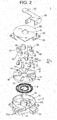
Fig. 2 is an exploded perspective view of the flat cable winding device shown inFig. 1 ; -
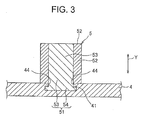
Fig. 3 is a cross-sectional view showing a state in which a roller constituting the flat cable winding device is pivotally-supported at a rotating table (i.e. rotating body); -
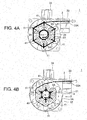
Figs. 4A and 4B are plan views illustrating an operation of the flat cable winding device shown inFig. 1 , in whichFig. 4A shows how a flat cable is led out, andFig. 4B shows how the flat cable is wound up; -
Fig. 5 is a plan view of a conventional flat cable winding device; and -
Figs. 6A through 6C illustrate an operation of the flat cable winding device shown inFig. 5 . - In the following, a flat cable winding device according to one embodiment of the present invention is explained in reference to
Figs. 1 through 4B . A flatcable winding device 1 is configured to wind up aflat cable 2 wired between a vehicle and a sliding seat slidably provided to a floor of the vehicle, for example. One end of theflat cable 2 is connected to a connector and such provided at the floor side, and another end of theflat cable 2 guided along a slide rail is connected to a connector and such provided at the sliding seat side. - The
flat cable 2 is formed into a thin band plate-like shape having flexibility, and includes a plurality of parallely-arranged core wires and an insulating cover covering the respective core wires. The core wire is formed by a plurality of twisted conducting wires, and the cover portion is made of synthetic resin. This embodiment shows an example of using theflat cable 2 having the plurality of parallely-arranged core wires; however, the flat cable may have any cross-sectional shape, and the configuration of the core wire and the insulating cover may be selected arbitrarily. - As shown in
Figs. 1 and2 , the flatcable winding device 1 includes acase 3 housing the woundflat cable 2, a rotating table 4 as a rotating body rotatably provided in thecase 3, a plurality of (six, in this embodiment)rollers 5 rotatably supported on the rotating table 4, and a spiral spring 6 (shown inFig. 2 ) as a biasing element configured to bias the rotating table 4 in a winding direction of theflat cable 2. Thecase 3 includes alower case 3A housing the rotating table 4 and thespiral spring 6, and anupper case 3B (shown inFig. 2 ) configured to cover anupper face 7B of thelower case 3A so as to close thecase 3 in a hollow fashion. Acentral shaft 7 which rotatably and pivotally supports the rotating table 4 is vertically arranged at a substantially center of thelower case 3A. - As shown in
Fig. 2 , thelower case 3A is horizontally disposed on the floor of the vehicle, and includes abottom portion 31 opposed to the floor, aperipheral wall 32 vertically arranged in a substantially cylindrical shape along an outer periphery of thebottom portion 31, a cable lead outportion 33 for leading out the another end side of theflat cable 2 to the outside, and acable protection portion 34 for protecting the one end side of theflat cable 2 drawn out from thecase 3. Theupper case 3B has a circular disc-like shape in an entire shape, and includes, at its center, atop face portion 35 having aninsertion hole 3a through which theflat cable 2 is inserted, ahanging wall 36 hanging down in a substantially cylindrical fashion along an outer periphery of thetop face portion 35 and arranged to overlap with theperipheral wall 32 of thelower case 3A, acable guide portion 37 guiding the one end side of theflat cable 2 from thecentral shaft 7 to thecable protection portion 34, and acover portion 38 covering an upper portion of thecable protection portion 34. - As shown in
Fig. 2 , thecentral shaft 7 is vertically arranged at an internal face of thebottom portion 31 in thelower case 3A and is substantially columnar in entire shape, such that the rotating table 4 is rotatably supported by acircumferential face 7A of thecentral shaft 7. Thecentral shaft 7 includes aslit 71 formed by being cut from acircumference face 7A toward a center and opening to theupper face 7B, a lockinggroove 72 formed by being cut from an opposite side of theslit 71 and opening to theupper face 7B, and a communication groove 73 communicating theslit 71 and the lockinggroove 72, which together form a crank shape in planar view. Theslit 71 locks the one end side of theflat cable 2 by passing the one end side of theflat cable 2 therethrough. The one end side of theflat cable 2 passed thorugh theslit 71 is passed through the communication groove 73 and bent, and then it is led out from theupper face 7B of thecentral shaft 7 and guided to thecable guide portion 37 of theupper case 3B. Then, the one end side of theflat cable 2 is guided from thecable guide portion 37 to thecable protection portion 34 of thelower case 3A, led out to the outside of thecase 3 and connected to a connector and such at the floor side. - The cable lead out
portion 33 is arranged to project from the outer face of theperipheral wall 32 of thelower case 3A, and includes a plurality of groove portions (insertion holes) 33A for housing theflat cable 2 formed at itsupper face 7B. The plurality ofgroove portions 33A is arranged to communicate between inside and outside of thelower case 3A, and is extending linearly along a slide direction of the slide rail. Theflat cable 2 is passed through a predetermined onegroove portion 33A of the plurality ofgroove portions 33A, by which the another end side of theflat cable 2 is wired from the inside to outside of thecase 3. When winding theflat cable 2 to the inside of thecase 3 or when leading out theflat cable 2 to the outside of thecase 3, theflat cable 2 is guided along thegroove portion 33A. - As shown in
Fig. 2 , the rotating table 4 is formed into a circular disc-like shape in entire shape and includes, at its center, ahole 4a for passing thecentral shaft 7 therethrough. An upper face of the rotating table 4 is provided with sixrail portions 41 which are radially-arranged about thecentral shaft 7 as a center, and are configured to slide theroller 5 in a radial direction of the rotating table 4. - As shown in
Figs. 2 and3 , eachrail portion 41 is formed concave with respect to theupper face 7B of the rotation table 4, and includes anelongated hole 42 extending radially outward from thecentral shaft 7 side and acircular portion 43 provided at an end of theelongated hole 42 located radially-outward of the rotating table 4. Theelongated hole 42 includ5es a pair of lockingportions 44 for attaching theroller 5 to the rotating table 4. The pair of lockingportions 44 is extending toward each other from upper ends in the widthwise direction of theelongated holes 42 and is formed throughout the entire longitudinal length of theelongated hole 42. Theelongated hole 42 is formed such that the width of the space located lower than the pair of lockingportions 44 is equal to the diameter dimension of thecircular portion 43. - As shown in
Fig. 2 , each of the sixrollers 5 includes ashaft portion 51 and aroller body 52, theroller body 52 being formed in a cylindrical shape and including, at its center, ahole portion 5a though which theshaft portion 1 is inserted. When therespective rollers 5 are slid toward thecentral shaft 7 while being slidably attached to the rotating table 4, the sixrollers 5 are positioned so as to align along the circumferential direction of the rotating table 4. Threerollers 5 of the sixrollers 5 correspond to reversingrollers 5A (shown inFig. 1 ), and the reversingrollers 5A are arranged alternatively with therollers 5 others than the reversingrollers 5A. The reversingrollers 5A reverse the another end side of theflat cable 2 wound around thecentral shaft 7. - As shown in
Fig. 3 , theshaft portion 51 includes acolumnar shaft body 53 and a to-be-locked portion 54 extending in the outward direction from theshaft body 53, the to-be-locked portion 54 being configured to be locked at the lockingportion 44 and having a diameter larger than a diameter of theshaft body 53. This to-be-locked portion 54 is provided at an end in the longitudinal direction (a height direction Y) of theshaft body 53, and a dimension in the radial direction of the to-be-locked portion 54 is formed equal with the diameter dimension of thecircular portion 43. In addition, a dimension in the height direction Y of the to-be-locked portion 54 is formed smaller than a dimension in the height direction Y of the lower space of theelongated hole 42. - The
spiral spring 6 is formed by spirally winding a wire metal having elasticity. An end of thespiral spring 6 adjacent to its center is passed through and fixed to the lockinggroove 72 of thecentral shaft 7, and an end of thespiral spring 6 at its outer periphery side is locked at a lower face of the rotating table 4, thereby biasing the rotating table 4 in the winding direction of theflat cable 2. That is, firstly, the rotating table 4 is rotated in a direction opposed to the winding direction for a predetermined times so that thespiral spring 6 stores the biasing force, and after that, theflat cable 2 reversed by the reversingroller 5A is wound around the outer circumferences of the plurality ofrollers spiral spring 6, and with this biasing force theflat cable 2 is wound by thecentral shaft 7 and the rotation table 4. - Next, a method for mounting the rollers 5 (the reversing
roller 5A) to the rotating table 4 of the flatcable winding device 1 is explained. Firstly, theshaft portion 51 is brought closer to therail portions 41 of the rotating table 4 with the to-be-locked portion 54 side ahead, and the to-be-locked portion 54 is overlapped to a lower face of thecircular portion 43 and the to-be-locked portion 54 is slid toward thecentral shaft 7. In this manner, the pair of lockingportions 44 enters between theshaft body 53 of theshaft portion 51 and the to-be-locked portion 54, thereby slidably attaching theshaft portion 51 to the rotating table 4 so as to be slidable in the radial direction of the rotating table 4. Then, by inserting theshaft portion 51 into thehole 5a of theroller body 52, theroller body 52 is rotatably mounted to theshaft portion 51. - In the following, action of the
flat cable 2 in the flatcable winding device 1 is explained in reference toFigs. 4A, 4B . Firstly, the plurality ofrollers central shaft 7 of the rotating table 4 so it is separated from thecentral shaft 7. One end sides of the plural pieces (three pieces, in this embodiment) of theflat cables 2 are overlapped together and locked at theslit 71, while the another end sides thereof are arranged independent one by one. Eachflat cable 2 is wired along the winding direction of each reversingroller 5A, and then the another end sides of theflat cable 2 are reversed by the respective reversingrollers 5A and led out from thegroove portion 33A to the outside of thecase 3. InFigs. 4A, 4B , theupper case 3B is omitted. - When the rotating table 4 is rotated in the winding direction by the restoring force of the
spiral spring 6 as described above, theflat cables 2 are wound around the outer circumference of thecentral shaft 7 and the outer circumferences of the plurality of therollers portion 21 formed by theflat cables 2 wound along the outer circumference of thecentral shaft 7 and an outer windingportion 22 formed by theflat cables 2 wound along the outer circumferences of the plurality of therollers rollers 5A are slid toward thecentral shaft 7 by the winding force of the outer windingportion 22 and are pushed toward the inner windingportion 21. As shown inFig. 4A , as theflat cables 2 are wound, a number of windings of theflat cable 2 to thecentral shaft 7 is increased, and the diameter dimension of the inner windingportion 21 is increased. Thus, the plurality of therollers portion 21 and slid radially-outward of the rotating table 4. The reversingroller 5A is rotated (rotated on its axis) while being pushed toward the inner windingportion 21, and delivers theflat cable 2 which is unwound from thecentral shaft 7 to thecentral shaft 7 side. In this manner, theflat cables 2 are wound up. - Referring to
Fig. 4B , when theflat cables 2 are drawn out from the state in which theflat cables 2 are wound inside of thecase 3 as described above, the rotating table 4 is rotated in the opposite direction of the winding direction, and the outer windingportion 22 is unwound and led out to the outside of thecase 3. At the same time, the inner windingportion 21 is unwound, and theflat cables 2 are delivered to the outer windingportion 22 via the reversingrollers 5A, thereby leading out theflat cables 2. As theflat cables 2 are led out, the number of windings of theflat cable 2 to thecentral shaft 7 is decreased, and the diameter dimension of the inner windingportion 21 is reduced. Thus, the reversingrollers 5A are pushed toward thecentral shaft 7 by the winding force of the outer windingportion 22 and slid toward thecentral shaft 7. During this time, the reversingroller 5A is rotated (rotated on its axis) while being pushed toward the inner windingportion 21 by the outer windingportion 22, and delivers theflat cable 2 unwound from thecentral shaft 7 toward the outer circumferences of the plurality ofrollers flat cable 2 to the outside of thecase 3. - According to the embodiment explained above, the reversing
roller 5A is configured to be slidable in the radial direction of the rotating table 4, and the reversingroller 5A is pushed toward the inner windingportion 21 by the outer windingportion 22. Thus, during the leading out of theflat cable 2, the reversingroller 5A, while being pushed toward the inner windingportion 21, is rotated with involving theflat cable 2, and theflat cable 2 unwound from thecentral shaft 7 is forcibly delivered toward the outer circumference of the reversingroller 5A. As a result, the chance of producing the slack of the flat cable at around the central shaft 7 (at the inner winding portion 21) is reduced, preventing the interference of the slackenedflat cable 2 with the plurality of rollers 5 (the reversingroller 5A). Thus, the rotation of the rotating table 4 is not impeded, achieving smooth winding and leading out of theflat cable 2. - Furthermore, when retaining the one end side of the
flat cable 2 to thecentral shaft 7, the plurality of the rollers 5 (reversingroller 5A) is slid away from thecentral shaft 7 of the rotating table 4 and the plurality of therollers 5 is separated from thecentral shaft 7 to form a space around thecentral shaft 7. Thus, theflat cable 2 can be easily retained to thecentral shaft 7. - The aforementioned embodiment is only a representative embodiment of the present invention, and the present invention is not limited of this embodiment. That is, the present invention can be modified and performed in various ways without departing from the gist of the present invention.
- For example, although the above-described embodiment shows the flat cable winding device used for an electric wire wiring device for sliding seat, a winding device according to the present invention may be used, not just for an electric wire wiring device for sliding seat, but for an electric wire wiring device for slide door, and may be used for a wiring device for wiring an electric wire at a rotatable opening/closing door or a bonnet. Furthermore, a winding device according to the present invention may be used, not just for a vehicle, but for a wiring device for wiring an electric wire across a movable part of an equipment or a device having various movable parts. Furthermore, although the above-described embodiment shows a winding device for winding a single flat cable for simplicity, the present invention may be used for a winding device for winding plurality of flat cables bundled together.
-
- 1
- flat cable winding device
- 2
- flat cable
- 3
- case
- 4
- rotating table (rotating body)
- 5
- roller
- 5A
- reversing roller
- 6
- spiral spring (biasing element)
- 7
- central shaft
- 21
- inner winding portion
- 22
- outer winding portion
Claims (1)
- A flat cable winding device for winding one end side of a flat cable and leading out another end side of the flat cable, the flat cable winding device comprising:a case having an insertion hole through which the flat cable is inserted;a central shaft provided in the case and retaining the one end side of the flat cable;a rotating body configured to rotate about the central shaft; anda biasing element configured to bias the rotating body in a winding direction of the flat cable,wherein the rotating body includes a plurality of rollers arranged along a circumferential direction of the rotating body and configured to slide in a radial direction of the rotating body,wherein at least one of the plurality of rollers is a reversing roller configured to reverse the flat cable entered from the insertion hole of the case toward the central shaft, andwherein,when the rotating body which is biased by the biasing element is rotated in the winding direction and the flat cable is wound up so as to form an inner winding portion formed by the flat cable wound around the central shaft and an outer winding portion formed by the flat cable wound around outer circumferences of the plurality of rollers,the plurality of rollers is pushed toward the inner winding portion by the outer winding portion.
Applications Claiming Priority (2)
| Application Number | Priority Date | Filing Date | Title |
|---|---|---|---|
| JP2012031397A JP5896409B2 (en) | 2012-02-16 | 2012-02-16 | Flat cable winding device |
| PCT/JP2013/053339 WO2013122077A1 (en) | 2012-02-16 | 2013-02-13 | Flat cable winding device |
Publications (3)
| Publication Number | Publication Date |
|---|---|
| EP2816694A1 true EP2816694A1 (en) | 2014-12-24 |
| EP2816694A4 EP2816694A4 (en) | 2015-10-28 |
| EP2816694B1 EP2816694B1 (en) | 2018-09-26 |
Family
ID=48984187
Family Applications (1)
| Application Number | Title | Priority Date | Filing Date |
|---|---|---|---|
| EP13749897.8A Active EP2816694B1 (en) | 2012-02-16 | 2013-02-13 | Flat cable winding device |
Country Status (5)
| Country | Link |
|---|---|
| US (1) | US9409746B2 (en) |
| EP (1) | EP2816694B1 (en) |
| JP (1) | JP5896409B2 (en) |
| CN (1) | CN104115356B (en) |
| WO (1) | WO2013122077A1 (en) |
Cited By (1)
| Publication number | Priority date | Publication date | Assignee | Title |
|---|---|---|---|---|
| EP3629436A1 (en) * | 2018-09-26 | 2020-04-01 | Yazaki Corporation | Flat cable winding device and flat cable routing structure |
Families Citing this family (17)
| Publication number | Priority date | Publication date | Assignee | Title |
|---|---|---|---|---|
| JP5827819B2 (en) * | 2011-05-12 | 2015-12-02 | 矢崎総業株式会社 | Flat cable routing structure |
| JP6100015B2 (en) * | 2012-02-16 | 2017-03-22 | 矢崎総業株式会社 | Flat cable winding device and assembly method thereof |
| JP5847614B2 (en) * | 2012-03-09 | 2016-01-27 | 矢崎総業株式会社 | Flat cable winding device |
| JP6025205B2 (en) * | 2013-03-14 | 2016-11-16 | 矢崎総業株式会社 | Flat cable winding device |
| JP6285712B2 (en) * | 2013-12-26 | 2018-02-28 | 矢崎総業株式会社 | Flat cable winding device |
| JP6453671B2 (en) * | 2015-03-02 | 2019-01-16 | 矢崎総業株式会社 | Extra length absorber |
| JP6276225B2 (en) * | 2015-08-04 | 2018-02-07 | 矢崎総業株式会社 | Wire harness winding device |
| DE102015118543A1 (en) * | 2015-10-29 | 2017-05-04 | Valeo Schalter Und Sensoren Gmbh | Protective cover for a coil spring housing, clock spring housing assembly and vehicle having such a clock spring housing assembly |
| JP6687404B2 (en) * | 2016-02-03 | 2020-04-22 | 矢崎総業株式会社 | Wire harness winding device and harness wiring structure |
| JP6793545B2 (en) * | 2016-12-28 | 2020-12-02 | 矢崎総業株式会社 | Winding device and wiring structure |
| CN106953290B (en) * | 2017-03-08 | 2018-04-17 | 北京环境特性研究所 | A kind of turntable routing device |
| CN107140481B (en) * | 2017-06-12 | 2019-03-26 | 北京机械设备研究所 | The draw off gear and power supply cabinet of cable |
| JP6856587B2 (en) * | 2018-08-20 | 2021-04-07 | 矢崎総業株式会社 | Flat cable winding device and its assembly method |
| JP2020114082A (en) * | 2019-01-10 | 2020-07-27 | 矢崎総業株式会社 | Wire harness for seat |
| JP2020141541A (en) * | 2019-03-01 | 2020-09-03 | 株式会社タチエス | Bearing structure with power supply path |
| CN112172557B (en) * | 2020-08-13 | 2021-10-26 | 大连海洋大学 | New forms of energy are charged with rolling joint that charges |
| DE202020105121U1 (en) * | 2020-09-04 | 2021-10-07 | Igus Gmbh | Dividing bar for dividing an energy chain inside |
Family Cites Families (14)
| Publication number | Priority date | Publication date | Assignee | Title |
|---|---|---|---|---|
| US5277604A (en) * | 1991-04-05 | 1994-01-11 | Alps Electric Co., Ltd. | Clock spring connector |
| JP3016898B2 (en) * | 1991-04-05 | 2000-03-06 | アルプス電気株式会社 | Cable reel |
| JP2999627B2 (en) * | 1992-05-25 | 2000-01-17 | アルプス電気株式会社 | Cable reel |
| JPH07147175A (en) * | 1993-11-25 | 1995-06-06 | Nippondenso Co Ltd | Cable reel |
| TW317043B (en) * | 1994-07-19 | 1997-10-01 | Methode Electronics Inc | |
| JP3595130B2 (en) * | 1997-10-17 | 2004-12-02 | 矢崎総業株式会社 | Flat cable winding device |
| JP4101001B2 (en) * | 2002-08-29 | 2008-06-11 | 古河電気工業株式会社 | Flat cable winding number design method for power feeding device to moving body and power feeding device to moving body |
| US6780032B2 (en) * | 2002-10-07 | 2004-08-24 | Tyco Electronics Corporation | Loop back clockspring connector having high current capacity |
| JP4205516B2 (en) * | 2003-04-11 | 2009-01-07 | 古河電気工業株式会社 | Flat cable winding and unwinding device |
| JP4355229B2 (en) * | 2004-02-12 | 2009-10-28 | アルプス電気株式会社 | Rotating connector |
| JP2006120512A (en) * | 2004-10-22 | 2006-05-11 | Alps Electric Co Ltd | Rotary connector |
| JP6066543B2 (en) * | 2010-11-24 | 2017-01-25 | 矢崎総業株式会社 | Flat harness winding device |
| JP2013151335A (en) * | 2012-01-24 | 2013-08-08 | Yazaki Corp | Flat cable winding device and flat cable wiring structure |
| JP6100015B2 (en) * | 2012-02-16 | 2017-03-22 | 矢崎総業株式会社 | Flat cable winding device and assembly method thereof |
-
2012
- 2012-02-16 JP JP2012031397A patent/JP5896409B2/en active Active
-
2013
- 2013-02-13 CN CN201380009768.9A patent/CN104115356B/en active Active
- 2013-02-13 US US14/375,058 patent/US9409746B2/en active Active
- 2013-02-13 EP EP13749897.8A patent/EP2816694B1/en active Active
- 2013-02-13 WO PCT/JP2013/053339 patent/WO2013122077A1/en not_active Ceased
Cited By (1)
| Publication number | Priority date | Publication date | Assignee | Title |
|---|---|---|---|---|
| EP3629436A1 (en) * | 2018-09-26 | 2020-04-01 | Yazaki Corporation | Flat cable winding device and flat cable routing structure |
Also Published As
| Publication number | Publication date |
|---|---|
| EP2816694B1 (en) | 2018-09-26 |
| EP2816694A4 (en) | 2015-10-28 |
| CN104115356B (en) | 2017-04-26 |
| WO2013122077A1 (en) | 2013-08-22 |
| JP2013169093A (en) | 2013-08-29 |
| JP5896409B2 (en) | 2016-03-30 |
| US9409746B2 (en) | 2016-08-09 |
| CN104115356A (en) | 2014-10-22 |
| US20150001327A1 (en) | 2015-01-01 |
Similar Documents
| Publication | Publication Date | Title |
|---|---|---|
| US9409746B2 (en) | Flat cable winding device | |
| EP2816693B1 (en) | Flat cable take-up device and method for assembling same | |
| JP6025205B2 (en) | Flat cable winding device | |
| JP2010172116A (en) | Harness winding type power supply device | |
| US8911239B2 (en) | Rotatable connector device | |
| JP2019218150A (en) | Flat cable winding device | |
| JP5856492B2 (en) | Flat cable winding device and flat cable routing structure | |
| EP2555345A1 (en) | Rotary connector device | |
| CN106663499A (en) | Flat flexible cable and apparatus | |
| WO2014175204A1 (en) | Flat cable routing structure | |
| JP2013151335A (en) | Flat cable winding device and flat cable wiring structure | |
| JP4191184B2 (en) | Cable winding device | |
| JP5847614B2 (en) | Flat cable winding device | |
| CN220612118U (en) | Thread cutting device | |
| JP6285712B2 (en) | Flat cable winding device | |
| JP6265708B2 (en) | Cable winding device | |
| JP2001218350A (en) | Wire harness winding device | |
| JP2004345598A (en) | Current feeding device for slide door | |
| JP2004095209A (en) | Method of designing winding number of flat cable of power supply device to mobile object, power supply device to mobile object, power supply method to mobile object, and power supply device to mobile object | |
| KR200344728Y1 (en) | Apparatus for winding a cord | |
| JP2021083280A (en) | Flat cable winding device and flat cable wiring structure |
Legal Events
| Date | Code | Title | Description |
|---|---|---|---|
| PUAI | Public reference made under article 153(3) epc to a published international application that has entered the european phase |
Free format text: ORIGINAL CODE: 0009012 |
|
| 17P | Request for examination filed |
Effective date: 20140916 |
|
| AK | Designated contracting states |
Kind code of ref document: A1 Designated state(s): AL AT BE BG CH CY CZ DE DK EE ES FI FR GB GR HR HU IE IS IT LI LT LU LV MC MK MT NL NO PL PT RO RS SE SI SK SM TR |
|
| AX | Request for extension of the european patent |
Extension state: BA ME |
|
| DAX | Request for extension of the european patent (deleted) | ||
| RA4 | Supplementary search report drawn up and despatched (corrected) |
Effective date: 20150928 |
|
| RIC1 | Information provided on ipc code assigned before grant |
Ipc: B65H 75/44 20060101ALI20150922BHEP Ipc: H01R 35/02 20060101ALI20150922BHEP Ipc: H02G 11/00 20060101AFI20150922BHEP Ipc: B60R 16/027 20060101ALI20150922BHEP Ipc: H02G 11/02 20060101ALI20150922BHEP |
|
| STAA | Information on the status of an ep patent application or granted ep patent |
Free format text: STATUS: EXAMINATION IS IN PROGRESS |
|
| 17Q | First examination report despatched |
Effective date: 20170404 |
|
| GRAP | Despatch of communication of intention to grant a patent |
Free format text: ORIGINAL CODE: EPIDOSNIGR1 |
|
| STAA | Information on the status of an ep patent application or granted ep patent |
Free format text: STATUS: GRANT OF PATENT IS INTENDED |
|
| INTG | Intention to grant announced |
Effective date: 20180620 |
|
| GRAS | Grant fee paid |
Free format text: ORIGINAL CODE: EPIDOSNIGR3 |
|
| GRAA | (expected) grant |
Free format text: ORIGINAL CODE: 0009210 |
|
| STAA | Information on the status of an ep patent application or granted ep patent |
Free format text: STATUS: THE PATENT HAS BEEN GRANTED |
|
| AK | Designated contracting states |
Kind code of ref document: B1 Designated state(s): AL AT BE BG CH CY CZ DE DK EE ES FI FR GB GR HR HU IE IS IT LI LT LU LV MC MK MT NL NO PL PT RO RS SE SI SK SM TR |
|
| REG | Reference to a national code |
Ref country code: GB Ref legal event code: FG4D |
|
| REG | Reference to a national code |
Ref country code: CH Ref legal event code: EP |
|
| REG | Reference to a national code |
Ref country code: AT Ref legal event code: REF Ref document number: 1047158 Country of ref document: AT Kind code of ref document: T Effective date: 20181015 |
|
| REG | Reference to a national code |
Ref country code: IE Ref legal event code: FG4D |
|
| REG | Reference to a national code |
Ref country code: DE Ref legal event code: R096 Ref document number: 602013044200 Country of ref document: DE |
|
| REG | Reference to a national code |
Ref country code: NL Ref legal event code: MP Effective date: 20180926 |
|
| PG25 | Lapsed in a contracting state [announced via postgrant information from national office to epo] |
Ref country code: SE Free format text: LAPSE BECAUSE OF FAILURE TO SUBMIT A TRANSLATION OF THE DESCRIPTION OR TO PAY THE FEE WITHIN THE PRESCRIBED TIME-LIMIT Effective date: 20180926 Ref country code: BG Free format text: LAPSE BECAUSE OF FAILURE TO SUBMIT A TRANSLATION OF THE DESCRIPTION OR TO PAY THE FEE WITHIN THE PRESCRIBED TIME-LIMIT Effective date: 20181226 Ref country code: LT Free format text: LAPSE BECAUSE OF FAILURE TO SUBMIT A TRANSLATION OF THE DESCRIPTION OR TO PAY THE FEE WITHIN THE PRESCRIBED TIME-LIMIT Effective date: 20180926 Ref country code: FI Free format text: LAPSE BECAUSE OF FAILURE TO SUBMIT A TRANSLATION OF THE DESCRIPTION OR TO PAY THE FEE WITHIN THE PRESCRIBED TIME-LIMIT Effective date: 20180926 Ref country code: RS Free format text: LAPSE BECAUSE OF FAILURE TO SUBMIT A TRANSLATION OF THE DESCRIPTION OR TO PAY THE FEE WITHIN THE PRESCRIBED TIME-LIMIT Effective date: 20180926 Ref country code: GR Free format text: LAPSE BECAUSE OF FAILURE TO SUBMIT A TRANSLATION OF THE DESCRIPTION OR TO PAY THE FEE WITHIN THE PRESCRIBED TIME-LIMIT Effective date: 20181227 Ref country code: NO Free format text: LAPSE BECAUSE OF FAILURE TO SUBMIT A TRANSLATION OF THE DESCRIPTION OR TO PAY THE FEE WITHIN THE PRESCRIBED TIME-LIMIT Effective date: 20181226 |
|
| REG | Reference to a national code |
Ref country code: LT Ref legal event code: MG4D |
|
| PG25 | Lapsed in a contracting state [announced via postgrant information from national office to epo] |
Ref country code: AL Free format text: LAPSE BECAUSE OF FAILURE TO SUBMIT A TRANSLATION OF THE DESCRIPTION OR TO PAY THE FEE WITHIN THE PRESCRIBED TIME-LIMIT Effective date: 20180926 Ref country code: HR Free format text: LAPSE BECAUSE OF FAILURE TO SUBMIT A TRANSLATION OF THE DESCRIPTION OR TO PAY THE FEE WITHIN THE PRESCRIBED TIME-LIMIT Effective date: 20180926 Ref country code: LV Free format text: LAPSE BECAUSE OF FAILURE TO SUBMIT A TRANSLATION OF THE DESCRIPTION OR TO PAY THE FEE WITHIN THE PRESCRIBED TIME-LIMIT Effective date: 20180926 |
|
| REG | Reference to a national code |
Ref country code: AT Ref legal event code: MK05 Ref document number: 1047158 Country of ref document: AT Kind code of ref document: T Effective date: 20180926 |
|
| PG25 | Lapsed in a contracting state [announced via postgrant information from national office to epo] |
Ref country code: PL Free format text: LAPSE BECAUSE OF FAILURE TO SUBMIT A TRANSLATION OF THE DESCRIPTION OR TO PAY THE FEE WITHIN THE PRESCRIBED TIME-LIMIT Effective date: 20180926 Ref country code: NL Free format text: LAPSE BECAUSE OF FAILURE TO SUBMIT A TRANSLATION OF THE DESCRIPTION OR TO PAY THE FEE WITHIN THE PRESCRIBED TIME-LIMIT Effective date: 20180926 Ref country code: RO Free format text: LAPSE BECAUSE OF FAILURE TO SUBMIT A TRANSLATION OF THE DESCRIPTION OR TO PAY THE FEE WITHIN THE PRESCRIBED TIME-LIMIT Effective date: 20180926 Ref country code: IT Free format text: LAPSE BECAUSE OF FAILURE TO SUBMIT A TRANSLATION OF THE DESCRIPTION OR TO PAY THE FEE WITHIN THE PRESCRIBED TIME-LIMIT Effective date: 20180926 Ref country code: EE Free format text: LAPSE BECAUSE OF FAILURE TO SUBMIT A TRANSLATION OF THE DESCRIPTION OR TO PAY THE FEE WITHIN THE PRESCRIBED TIME-LIMIT Effective date: 20180926 Ref country code: AT Free format text: LAPSE BECAUSE OF FAILURE TO SUBMIT A TRANSLATION OF THE DESCRIPTION OR TO PAY THE FEE WITHIN THE PRESCRIBED TIME-LIMIT Effective date: 20180926 Ref country code: CZ Free format text: LAPSE BECAUSE OF FAILURE TO SUBMIT A TRANSLATION OF THE DESCRIPTION OR TO PAY THE FEE WITHIN THE PRESCRIBED TIME-LIMIT Effective date: 20180926 Ref country code: ES Free format text: LAPSE BECAUSE OF FAILURE TO SUBMIT A TRANSLATION OF THE DESCRIPTION OR TO PAY THE FEE WITHIN THE PRESCRIBED TIME-LIMIT Effective date: 20180926 Ref country code: IS Free format text: LAPSE BECAUSE OF FAILURE TO SUBMIT A TRANSLATION OF THE DESCRIPTION OR TO PAY THE FEE WITHIN THE PRESCRIBED TIME-LIMIT Effective date: 20190126 |
|
| PG25 | Lapsed in a contracting state [announced via postgrant information from national office to epo] |
Ref country code: SK Free format text: LAPSE BECAUSE OF FAILURE TO SUBMIT A TRANSLATION OF THE DESCRIPTION OR TO PAY THE FEE WITHIN THE PRESCRIBED TIME-LIMIT Effective date: 20180926 Ref country code: PT Free format text: LAPSE BECAUSE OF FAILURE TO SUBMIT A TRANSLATION OF THE DESCRIPTION OR TO PAY THE FEE WITHIN THE PRESCRIBED TIME-LIMIT Effective date: 20190126 Ref country code: SM Free format text: LAPSE BECAUSE OF FAILURE TO SUBMIT A TRANSLATION OF THE DESCRIPTION OR TO PAY THE FEE WITHIN THE PRESCRIBED TIME-LIMIT Effective date: 20180926 |
|
| REG | Reference to a national code |
Ref country code: DE Ref legal event code: R097 Ref document number: 602013044200 Country of ref document: DE |
|
| PG25 | Lapsed in a contracting state [announced via postgrant information from national office to epo] |
Ref country code: DK Free format text: LAPSE BECAUSE OF FAILURE TO SUBMIT A TRANSLATION OF THE DESCRIPTION OR TO PAY THE FEE WITHIN THE PRESCRIBED TIME-LIMIT Effective date: 20180926 |
|
| PLBE | No opposition filed within time limit |
Free format text: ORIGINAL CODE: 0009261 |
|
| STAA | Information on the status of an ep patent application or granted ep patent |
Free format text: STATUS: NO OPPOSITION FILED WITHIN TIME LIMIT |
|
| 26N | No opposition filed |
Effective date: 20190627 |
|
| REG | Reference to a national code |
Ref country code: CH Ref legal event code: PL |
|
| GBPC | Gb: european patent ceased through non-payment of renewal fee |
Effective date: 20190213 |
|
| PG25 | Lapsed in a contracting state [announced via postgrant information from national office to epo] |
Ref country code: MC Free format text: LAPSE BECAUSE OF FAILURE TO SUBMIT A TRANSLATION OF THE DESCRIPTION OR TO PAY THE FEE WITHIN THE PRESCRIBED TIME-LIMIT Effective date: 20180926 Ref country code: LU Free format text: LAPSE BECAUSE OF NON-PAYMENT OF DUE FEES Effective date: 20190213 Ref country code: SI Free format text: LAPSE BECAUSE OF FAILURE TO SUBMIT A TRANSLATION OF THE DESCRIPTION OR TO PAY THE FEE WITHIN THE PRESCRIBED TIME-LIMIT Effective date: 20180926 |
|
| REG | Reference to a national code |
Ref country code: BE Ref legal event code: MM Effective date: 20190228 |
|
| REG | Reference to a national code |
Ref country code: IE Ref legal event code: MM4A |
|
| PG25 | Lapsed in a contracting state [announced via postgrant information from national office to epo] |
Ref country code: CH Free format text: LAPSE BECAUSE OF NON-PAYMENT OF DUE FEES Effective date: 20190228 Ref country code: LI Free format text: LAPSE BECAUSE OF NON-PAYMENT OF DUE FEES Effective date: 20190228 |
|
| PG25 | Lapsed in a contracting state [announced via postgrant information from national office to epo] |
Ref country code: IE Free format text: LAPSE BECAUSE OF NON-PAYMENT OF DUE FEES Effective date: 20190213 Ref country code: GB Free format text: LAPSE BECAUSE OF NON-PAYMENT OF DUE FEES Effective date: 20190213 |
|
| PG25 | Lapsed in a contracting state [announced via postgrant information from national office to epo] |
Ref country code: FR Free format text: LAPSE BECAUSE OF NON-PAYMENT OF DUE FEES Effective date: 20190228 Ref country code: BE Free format text: LAPSE BECAUSE OF NON-PAYMENT OF DUE FEES Effective date: 20190228 |
|
| PG25 | Lapsed in a contracting state [announced via postgrant information from national office to epo] |
Ref country code: TR Free format text: LAPSE BECAUSE OF FAILURE TO SUBMIT A TRANSLATION OF THE DESCRIPTION OR TO PAY THE FEE WITHIN THE PRESCRIBED TIME-LIMIT Effective date: 20180926 |
|
| PG25 | Lapsed in a contracting state [announced via postgrant information from national office to epo] |
Ref country code: MT Free format text: LAPSE BECAUSE OF NON-PAYMENT OF DUE FEES Effective date: 20190213 |
|
| PG25 | Lapsed in a contracting state [announced via postgrant information from national office to epo] |
Ref country code: CY Free format text: LAPSE BECAUSE OF FAILURE TO SUBMIT A TRANSLATION OF THE DESCRIPTION OR TO PAY THE FEE WITHIN THE PRESCRIBED TIME-LIMIT Effective date: 20180926 |
|
| PG25 | Lapsed in a contracting state [announced via postgrant information from national office to epo] |
Ref country code: HU Free format text: LAPSE BECAUSE OF FAILURE TO SUBMIT A TRANSLATION OF THE DESCRIPTION OR TO PAY THE FEE WITHIN THE PRESCRIBED TIME-LIMIT; INVALID AB INITIO Effective date: 20130213 |
|
| PG25 | Lapsed in a contracting state [announced via postgrant information from national office to epo] |
Ref country code: MK Free format text: LAPSE BECAUSE OF FAILURE TO SUBMIT A TRANSLATION OF THE DESCRIPTION OR TO PAY THE FEE WITHIN THE PRESCRIBED TIME-LIMIT Effective date: 20180926 |
|
| PGFP | Annual fee paid to national office [announced via postgrant information from national office to epo] |
Ref country code: DE Payment date: 20241231 Year of fee payment: 13 |