EP2816542A1 - Display device - Google Patents
Display device Download PDFInfo
- Publication number
- EP2816542A1 EP2816542A1 EP13749298.9A EP13749298A EP2816542A1 EP 2816542 A1 EP2816542 A1 EP 2816542A1 EP 13749298 A EP13749298 A EP 13749298A EP 2816542 A1 EP2816542 A1 EP 2816542A1
- Authority
- EP
- European Patent Office
- Prior art keywords
- case
- circuit board
- connecting member
- display
- display device
- Prior art date
- Legal status (The legal status is an assumption and is not a legal conclusion. Google has not performed a legal analysis and makes no representation as to the accuracy of the status listed.)
- Withdrawn
Links
Images




Classifications
-
- H—ELECTRICITY
- H05—ELECTRIC TECHNIQUES NOT OTHERWISE PROVIDED FOR
- H05K—PRINTED CIRCUITS; CASINGS OR CONSTRUCTIONAL DETAILS OF ELECTRIC APPARATUS; MANUFACTURE OF ASSEMBLAGES OF ELECTRICAL COMPONENTS
- H05K7/00—Constructional details common to different types of electric apparatus
- H05K7/14—Mounting supporting structure in casing or on frame or rack
- H05K7/1417—Mounting supporting structure in casing or on frame or rack having securing means for mounting boards, plates or wiring boards
- H05K7/142—Spacers not being card guides
-
- G—PHYSICS
- G02—OPTICS
- G02F—OPTICAL DEVICES OR ARRANGEMENTS FOR THE CONTROL OF LIGHT BY MODIFICATION OF THE OPTICAL PROPERTIES OF THE MEDIA OF THE ELEMENTS INVOLVED THEREIN; NON-LINEAR OPTICS; FREQUENCY-CHANGING OF LIGHT; OPTICAL LOGIC ELEMENTS; OPTICAL ANALOGUE/DIGITAL CONVERTERS
- G02F1/00—Devices or arrangements for the control of the intensity, colour, phase, polarisation or direction of light arriving from an independent light source, e.g. switching, gating or modulating; Non-linear optics
- G02F1/01—Devices or arrangements for the control of the intensity, colour, phase, polarisation or direction of light arriving from an independent light source, e.g. switching, gating or modulating; Non-linear optics for the control of the intensity, phase, polarisation or colour
- G02F1/13—Devices or arrangements for the control of the intensity, colour, phase, polarisation or direction of light arriving from an independent light source, e.g. switching, gating or modulating; Non-linear optics for the control of the intensity, phase, polarisation or colour based on liquid crystals, e.g. single liquid crystal display cells
- G02F1/133—Constructional arrangements; Operation of liquid crystal cells; Circuit arrangements
- G02F1/1333—Constructional arrangements; Manufacturing methods
- G02F1/133308—Support structures for LCD panels, e.g. frames or bezels
-
- H—ELECTRICITY
- H05—ELECTRIC TECHNIQUES NOT OTHERWISE PROVIDED FOR
- H05K—PRINTED CIRCUITS; CASINGS OR CONSTRUCTIONAL DETAILS OF ELECTRIC APPARATUS; MANUFACTURE OF ASSEMBLAGES OF ELECTRICAL COMPONENTS
- H05K9/00—Screening of apparatus or components against electric or magnetic fields
- H05K9/0067—Devices for protecting against damage from electrostatic discharge
-
- G—PHYSICS
- G02—OPTICS
- G02F—OPTICAL DEVICES OR ARRANGEMENTS FOR THE CONTROL OF LIGHT BY MODIFICATION OF THE OPTICAL PROPERTIES OF THE MEDIA OF THE ELEMENTS INVOLVED THEREIN; NON-LINEAR OPTICS; FREQUENCY-CHANGING OF LIGHT; OPTICAL LOGIC ELEMENTS; OPTICAL ANALOGUE/DIGITAL CONVERTERS
- G02F1/00—Devices or arrangements for the control of the intensity, colour, phase, polarisation or direction of light arriving from an independent light source, e.g. switching, gating or modulating; Non-linear optics
- G02F1/01—Devices or arrangements for the control of the intensity, colour, phase, polarisation or direction of light arriving from an independent light source, e.g. switching, gating or modulating; Non-linear optics for the control of the intensity, phase, polarisation or colour
- G02F1/13—Devices or arrangements for the control of the intensity, colour, phase, polarisation or direction of light arriving from an independent light source, e.g. switching, gating or modulating; Non-linear optics for the control of the intensity, phase, polarisation or colour based on liquid crystals, e.g. single liquid crystal display cells
- G02F1/133—Constructional arrangements; Operation of liquid crystal cells; Circuit arrangements
- G02F1/1333—Constructional arrangements; Manufacturing methods
- G02F1/133308—Support structures for LCD panels, e.g. frames or bezels
- G02F1/133314—Back frames
-
- G—PHYSICS
- G02—OPTICS
- G02F—OPTICAL DEVICES OR ARRANGEMENTS FOR THE CONTROL OF LIGHT BY MODIFICATION OF THE OPTICAL PROPERTIES OF THE MEDIA OF THE ELEMENTS INVOLVED THEREIN; NON-LINEAR OPTICS; FREQUENCY-CHANGING OF LIGHT; OPTICAL LOGIC ELEMENTS; OPTICAL ANALOGUE/DIGITAL CONVERTERS
- G02F1/00—Devices or arrangements for the control of the intensity, colour, phase, polarisation or direction of light arriving from an independent light source, e.g. switching, gating or modulating; Non-linear optics
- G02F1/01—Devices or arrangements for the control of the intensity, colour, phase, polarisation or direction of light arriving from an independent light source, e.g. switching, gating or modulating; Non-linear optics for the control of the intensity, phase, polarisation or colour
- G02F1/13—Devices or arrangements for the control of the intensity, colour, phase, polarisation or direction of light arriving from an independent light source, e.g. switching, gating or modulating; Non-linear optics for the control of the intensity, phase, polarisation or colour based on liquid crystals, e.g. single liquid crystal display cells
- G02F1/133—Constructional arrangements; Operation of liquid crystal cells; Circuit arrangements
- G02F1/1333—Constructional arrangements; Manufacturing methods
- G02F1/133308—Support structures for LCD panels, e.g. frames or bezels
- G02F1/13332—Front frames
-
- G—PHYSICS
- G02—OPTICS
- G02F—OPTICAL DEVICES OR ARRANGEMENTS FOR THE CONTROL OF LIGHT BY MODIFICATION OF THE OPTICAL PROPERTIES OF THE MEDIA OF THE ELEMENTS INVOLVED THEREIN; NON-LINEAR OPTICS; FREQUENCY-CHANGING OF LIGHT; OPTICAL LOGIC ELEMENTS; OPTICAL ANALOGUE/DIGITAL CONVERTERS
- G02F2201/00—Constructional arrangements not provided for in groups G02F1/00 - G02F7/00
- G02F2201/46—Fixing elements
- G02F2201/465—Snap -fit
-
- G—PHYSICS
- G02—OPTICS
- G02F—OPTICAL DEVICES OR ARRANGEMENTS FOR THE CONTROL OF LIGHT BY MODIFICATION OF THE OPTICAL PROPERTIES OF THE MEDIA OF THE ELEMENTS INVOLVED THEREIN; NON-LINEAR OPTICS; FREQUENCY-CHANGING OF LIGHT; OPTICAL LOGIC ELEMENTS; OPTICAL ANALOGUE/DIGITAL CONVERTERS
- G02F2202/00—Materials and properties
- G02F2202/22—Antistatic materials or arrangements
Definitions
- the present invention relates to a display device that prevents a display from taking an electrical charge.
- a liquid crystal display device has a rectangular shape metal frame, and several claw portions formed at the metal frame are inserted into holes formed at a circuit board. Each claw portions are bent so that the metal frame is connected to a ground pattern, and the liquid crystal display device is fixed by the metal frame.
- Patent Literature 1 Japanese Unexamined Patent Application Publication No. 5-188388
- An object of the present invention is to provide a display device excellent in assembling.
- the first feature of the present invention is that a display device comprising: a display configured to have a conductive box case; a case configured to accommodate the display; and a connecting member configured to conduct the box case of the display and a ground of a circuit board; wherein the connecting member consisting an elastic contact armature, and the elastic contact armature configured to contact with the ground of a circuit board upon the circuit board is fixed to the case.
- the second feature of the present invention is that a display device comprising: a display configured to have a conductive box case; a case configured to accommodate the display; and a connecting member configured to conduct the box case of the display and a ground of a circuit board, a static electricity is discharged from the display to the circuit board; wherein the connecting member consisting a base configured to contact with the box case and an elastic contact armature configurd to contact with the ground of a circuit board upon the circuit board is fixed to the case, and a fix member fixing the display to the case as the base is to be sandwiched between the box case and the case.
- the third feature of the present invention is that the case further comprising an elastic locking armature configured to fix the circuit board.
- the fourth feature of the present invention is that the base further comprising a concave configured to dispose the base of the connecting member.
- the fifth feature of the present invention is that the case further comprising a through hole configured to insert the elastic contact armature of the connecting member.
- the sixth feature of the present invention is that the case further comprising a positioning member configured to position the circuit board.
- the seventh feature of the present invention is that the case further comprising a bottom wall configured to fix the display and a height of the elastic armature projecting from the back of the bottom wall is shorter than a height of the positioning member while the circuit board is not fixed to the case.
- a display device configures to be excellent in assembling a case to circuit board and conducting a box case to a ground of the circuit board.
- a first embodiment of the invention will be described below with an example of a cluster for a motor vehicle comprising a liquid crystal display 10, a case 20, a connecting member 30, a circuit board 40, a front cover 80, and a rear cover 90.
- the liquid crystal display 10 comprises a liquid crystal panel 11, a housing 12, a box case 13, and a flexible electric wiring member 14.
- the liquid crystal panel 11 is a liquid-crystal display formed of a thin film transistor (TFT) and a liquid crystal cell that polarizers are affixed to both side of the cell.
- TFT thin film transistor
- the liquid crystal is insulated into the pair of transparent panel which the transistor is embedded.
- the liquid crystal panel 11 is illuminated by a light which is store in the housing or a back light which has a light guiding member.
- a light diffusion member may be placed at the back side of a liquid crystal panel 11.
- the housing 12 of the liquid crystal display 10 is formed of a white resin, and the liquid crystal display panel 11 and the back light are stored.
- the box case 13 of the liquid crystal display 10 is formed of a conductive material such as metal, and comprises a front box case 13a and a rear box case 13b.
- the front box case 13a is formed to have an opening corresponding to the display of the liquid crystal display panel 11 in of a rectangle shape.
- the front box case 13a is fixed to the rear box case 13b with a hook (not shown), and the front box case 13a and the rear box case 13b are connected to each other to have electrical conductivity.
- a flexible electric wiring member14 is consisted of a flexible base film with designated pattern so as to be called a FPC.
- a distal part of the flexible electric wiring member14 is connected to the liquid crystal display panel 11 and an illumination device, and the other distal part is connected to a connector 41 of the circuit board 40.
- the liquid crystal display 10 is provided electric power form the circuit board 40 through the flexible electric wiring member 14, and input a designated data from an input control unit mounted on the circuit board 40, and displays remaining fuel amount and travel distance on the display of the liquid crystal display panel 11.
- a case 20 is formed of white resin and having the liquid crystal display 10 in a space formed with a side wall 21 and a bottom wall 29.
- the liquid crystal display 10 is fixed to the front side of the bottom wall 29.
- the bottom wall 29 of the case 20 has a rectangular shape hole that the elastic contact armature of the connecting member 30 passes thought, and a round shape hole that the screw 70 passes though and a rectangular shape hole that the flexible electric wiring member14 passes though.
- the base 31 of the connecting member 30 is placed inside of a concave portion 27 which is a part of the bottom wall 29.
- the case 20 is provided with the positioning member 22, the elastic locking armature 23, and the wall portion 26 to abut the side of the liquid crystal display 10.
- the positioning member 22 and elastic locking armature 23 are provided at the back of the bottom wall 29, and have designated height H3.
- the positioning member 22 of the case 20 has a base 22a and projection part 22b.
- the base 22a of the positioning member 22 forms columnar and the height of the base 22a is equal to the height of designated height described later.
- the projection part 22b of the positioning member 22 is projecting from the base 22a and inserted into a hole 42 of the circuit board 40.
- the elastic locking armature 23 of the case 20 is provided with the base 23a and a locking hook 23b.
- the base 23a of the elastic locking armature 23 is rod-shaped and rectangular section, and the height of the base 23a that will be described later is a sum of a designated height H1 and a thickness of the circuit board 40.
- the base 23a of the elastic locking armature 23 is inserted into a hole 43 of the circuit board 40 and the circuit board 40 is hooked to the locking hook 23b of the elastic locking armature 23.
- the circuit board 40 is fixed to the case 20 with the locking hook 23b of the elastic locking armature 23 with the designated height H1 from the bottom wall 29.
- the designated height H1 is a total height of the back of the bottom wall 29 to the front of the circuit board 40.
- a connecting member 30 is formed by pressing and cutting a thin conductive board.
- the connecting member 30 includes a base 31 and two elastic contact armatures 32.
- the base 31 of the connecting member 30 includes two round shape holes 31 a which the screws 70 are inserted and two rectangular shape holes 31 b which are produced when the connecting member 30 is pressed. Both round shape holes 31 a and rectangular shape holes 31 b are located in where they are bilateral symmetry.
- the base 31 of the connecting member 30 is placed in the concave portion 27 and sandwiched between the rear box case 13b of the liquid crystal display 10 and the bottom wall 29 of the case 20. Together with the liquid crystal display 10, the connecting member 30 is fixed to the bottom wall 29 of the case 20 with two screws 70.
- the connecting member 30 is fixed to the case 20 so that the elastic locking armatures 23 are bilateral symmetry with a central line S as an axis.
- the base 31 of the connecting member 30 attaches to rear box case 13b nearby the round shape holes 31 a.
- the distal portion 32a of the elastic contact armatures32 is curved to attache the ground pattern 44 of the circuit board 40.
- the other distal portion 32b of the elastic contact armatures 32 are situated sequentially to the base 31.
- the two elastic contact armatures32 are bilateral symmetry.
- the elastic contact armatures 32 of the connecting member 30 are inserted into a hole 24 of the case 20 and project the designated height H2 from the bake surface of the bottom wall 29 before the circuit board 40 is fixed to the case20 (see figure 4 ).
- the designated height H2 is slightly taller than the designated height H1 and slightly shorter than the designated height H3.
- the circuit board 40 is formed of glass reinforced plastics with copper tracks in the place of wires.
- the connector 41 is mounted on the back of the circuit board 40 so that the other distal portion of a flexible electric wiring member14 can be connected.
- the flexible print wiring member14 is inserted into the hole 28 of the case 20, and the distal part is connected to the liquid crystal display 10 and the other distal part is connected to the circuit board through the connector41.
- the circuit board 40 includes a round shape hole 42 corresponds to the positioning member 22 and a rectangular shape hole 43 corresponds to the elastic locking armatures 23 of the case 20.
- the projection part 22b of the positioning part 22 is inserted into the hole 42 of the circuit board 40.
- the elastic locking armatures 23 is locked to the hole 42 of the circuit board 40.
- a ground pattern 44 is mounted on the surface of the circuit board 40. Although the ground pattern 44 of the circuit board 40 is made of a soldering layer in this embodiment, the soldering layer is not necessary to be placed.
- the distal portion 32a of the elastic contact armatures 32 attaches to the ground pattern 44 of the circuit board 40.
- the circuit board 40 is fixed by the elastic locking armature 23 to the case 20 which the liquid crystal display 10 and the connecting member 30 are fixed, and the elastic contact armatures 32 of the connecting member 30 are electrically connected to the ground pattern 44 of the circuit board 40.
- the elastic locking armature 23 is deformed elastically and the distal portion 32a of the elastic locking armature 23 is pressed to the ground pattern 44 of the circuit board 40.
- the box case 13 of the liquid crystal display 10 and the ground pattern 44 of the circuit board 40 are electrically connected.
- a front cover 80 is formed of opaque resin, and consists of a rectangular shape opening 81 corresponding to the display of the liquid crystal display 10.
- the front cover 80 is fixed to a back cover 90 with an elastic locking armature 82.
- the back cover 90 is formed of opaque resin, and covers the back of the circuit board 40.
- the back cover 90 is fixed to the case 20 with the screws which are not shown in this embodiment.
- a connecting member 130 is provided by pressing and cutting a thin conductive board.
- the connecting member 130 includes a base 131 and two elastic contact armatures 132.
- the connecting member 130 is fixed to the case 20 with the screw 70 so that the base 131 is sandwiched between the box case 13 of the liquid crystal display 10 and the case 20.
- the base 131 of the connecting member 130 includes a round shape hole 131 a which the screws 70 are inserted, a rectangular shape holes 131 b which was opened when the connecting member 130 was pressed and cut, and a flange portion 131 c.
- a distal portion 132a of the elastic contact armatures 132 is curved to come in contact with the ground pattern 44 of the circuit board 40.
- the other distal portion 132b of the elastic contact armatures 132 are situated sequentially to the base 131.
- fixing the circuit board 40 to the case 20 and electrically connecting the ground pattern 44 of the circuit board 40 to the box case 13 of the liquid crystal display 10 may be processed at the same time.
- the static electricity charged on the liquid crystal display 10 is discharged through the connecting member 30 and the circuit board 40.
- the height of the elastic armature 32 (H2) projecting from the back of the bottom wall 29 is desirably shorter than the height of the positioning member 22 (H3) when the circuit board 40 is not fixed to the case 20.
- the elastic contact armatures 32 attaches the circuit board 40 so that the elastic contact armatures 32 does not obstruct an assembly of the circuit board 40.
- the height of the elastic contact armature 32 (H2) projecting from the back of the bottom wall 29 is taller than the height of the positioning member 22 when the circuit board 40 is not fixed to the case 20,. If the elastic contact armatures 32 attaches the circuit board 40 before positioning the projection part 22b to the hole 42 of the circuit board 40, it may disturb an assembly of the circuit board 40.
- the display was explained as liquid crystal display10 that is provided with the liquid crystal panel 11.
- the display may be explained as Organic Electro-Luminescence display that is provided with an Organic Electro-Luminescence panel.
- the circuit board 40 was fixed to the case 20 with the elastic locking armature 23, but the circuit board 40 may be fixed to the case 20 with screws.
- the present invention may be applied to a display device configures to be excellent in assembling a case to circuit board and conducting a box case to a ground of the circuit board.
Landscapes
- Physics & Mathematics (AREA)
- Engineering & Computer Science (AREA)
- Microelectronics & Electronic Packaging (AREA)
- Nonlinear Science (AREA)
- Mathematical Physics (AREA)
- Chemical & Material Sciences (AREA)
- Crystallography & Structural Chemistry (AREA)
- General Physics & Mathematics (AREA)
- Optics & Photonics (AREA)
- Devices For Indicating Variable Information By Combining Individual Elements (AREA)
- Liquid Crystal (AREA)
Abstract
Description
- The present invention relates to a display device that prevents a display from taking an electrical charge.
- Conventionally, a liquid crystal display device has a rectangular shape metal frame, and several claw portions formed at the metal frame are inserted into holes formed at a circuit board. Each claw portions are bent so that the metal frame is connected to a ground pattern, and the liquid crystal display device is fixed by the metal frame.
- Patent Literature 1: Japanese Unexamined Patent Application Publication No.
5-188388 - An object of the present invention is to provide a display device excellent in assembling.
- The first feature of the present invention is that a display device comprising: a display configured to have a conductive box case; a case configured to accommodate the display; and a connecting member configured to conduct the box case of the display and a ground of a circuit board; wherein the connecting member consisting an elastic contact armature, and the elastic contact armature configured to contact with the ground of a circuit board upon the circuit board is fixed to the case.
- The second feature of the present invention is that a display device comprising: a display configured to have a conductive box case; a case configured to accommodate the display; and a connecting member configured to conduct the box case of the display and a ground of a circuit board, a static electricity is discharged from the display to the circuit board; wherein the connecting member consisting a base configured to contact with the box case and an elastic contact armature configurd to contact with the ground of a circuit board upon the circuit board is fixed to the case, and a fix member fixing the display to the case as the base is to be sandwiched between the box case and the case.
- The third feature of the present invention is that the case further comprising an elastic locking armature configured to fix the circuit board.
- The fourth feature of the present invention is that the base further comprising a concave configured to dispose the base of the connecting member.
- The fifth feature of the present invention is that the case further comprising a through hole configured to insert the elastic contact armature of the connecting member.
- The sixth feature of the present invention is that the case further comprising a positioning member configured to position the circuit board.
- The seventh feature of the present invention is that the case further comprising a bottom wall configured to fix the display and a height of the elastic armature projecting from the back of the bottom wall is shorter than a height of the positioning member while the circuit board is not fixed to the case. Advantageous Effects of Invention
- As described above, according to the present invention, a display device configures to be excellent in assembling a case to circuit board and conducting a box case to a ground of the circuit board.
-
- [
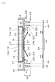
Fig. 1] Fig. 1 is a cross-sectional view of a display device according to a first embodiment of the present invention. - [
Fig. 2] Fig. 2 is a cross-sectional view of a main part of a display device according to a first embodiment of the present invention. - [
Fig. 3] Fig. 3 is a top and cross-sectional view of a connecting member according to a first embodiment of the present invention. - [
Fig. 4] Fig. 4 is a cross-sectional view of a display device according to a first embodiment of the present invention. - [
Fig. 5] Fig. 5 is a cross-sectional view of a display device according to a first embodiment of the present invention. - [
Fig. 6] Fig. 6 is a cross-sectional view of a main part of a display device according to a second embodiment of the present invention. - [
Fig. 7] Fig. 7 is a top and cross-sectional view of a connecting member according to a first embodiment of the present invention. - With reference to attached drawings
figure 1 to figure 5 , a first embodiment of the invention will be described below with an example of a cluster for a motor vehicle comprising aliquid crystal display 10, acase 20, a connectingmember 30, acircuit board 40, afront cover 80, and arear cover 90. - The
liquid crystal display 10 comprises aliquid crystal panel 11, ahousing 12, abox case 13, and a flexibleelectric wiring member 14. Theliquid crystal panel 11 is a liquid-crystal display formed of a thin film transistor (TFT) and a liquid crystal cell that polarizers are affixed to both side of the cell. The liquid crystal is insulated into the pair of transparent panel which the transistor is embedded. Theliquid crystal panel 11 is illuminated by a light which is store in the housing or a back light which has a light guiding member. A light diffusion member may be placed at the back side of aliquid crystal panel 11. - The
housing 12 of theliquid crystal display 10 is formed of a white resin, and the liquidcrystal display panel 11 and the back light are stored. Thebox case 13 of theliquid crystal display 10 is formed of a conductive material such as metal, and comprises afront box case 13a and arear box case 13b. Thefront box case 13a is formed to have an opening corresponding to the display of the liquidcrystal display panel 11 in of a rectangle shape. Thefront box case 13a is fixed to therear box case 13b with a hook (not shown), and thefront box case 13a and therear box case 13b are connected to each other to have electrical conductivity. - A flexible electric wiring member14 is consisted of a flexible base film with designated pattern so as to be called a FPC. A distal part of the flexible electric wiring member14 is connected to the liquid
crystal display panel 11 and an illumination device, and the other distal part is connected to aconnector 41 of thecircuit board 40. Theliquid crystal display 10 is provided electric power form thecircuit board 40 through the flexibleelectric wiring member 14, and input a designated data from an input control unit mounted on thecircuit board 40, and displays remaining fuel amount and travel distance on the display of the liquidcrystal display panel 11. - A
case 20 is formed of white resin and having theliquid crystal display 10 in a space formed with aside wall 21 and abottom wall 29. Theliquid crystal display 10 is fixed to the front side of thebottom wall 29. Thebottom wall 29 of thecase 20 has a rectangular shape hole that the elastic contact armature of the connectingmember 30 passes thought, and a round shape hole that thescrew 70 passes though and a rectangular shape hole that the flexible electric wiring member14 passes though. Thebase 31 of the connectingmember 30 is placed inside of aconcave portion 27 which is a part of thebottom wall 29. - The
case 20 is provided with thepositioning member 22, theelastic locking armature 23, and thewall portion 26 to abut the side of theliquid crystal display 10. Thepositioning member 22 andelastic locking armature 23 are provided at the back of thebottom wall 29, and have designated height H3. - The
positioning member 22 of thecase 20 has abase 22a andprojection part 22b. Thebase 22a of thepositioning member 22 forms columnar and the height of thebase 22a is equal to the height of designated height described later. Theprojection part 22b of thepositioning member 22 is projecting from thebase 22a and inserted into ahole 42 of thecircuit board 40. - The
elastic locking armature 23 of thecase 20 is provided with thebase 23a and alocking hook 23b. Thebase 23a of theelastic locking armature 23 is rod-shaped and rectangular section, and the height of thebase 23a that will be described later is a sum of a designated height H1 and a thickness of thecircuit board 40. Thebase 23a of theelastic locking armature 23 is inserted into ahole 43 of thecircuit board 40 and thecircuit board 40 is hooked to thelocking hook 23b of theelastic locking armature 23. Thecircuit board 40 is fixed to thecase 20 with thelocking hook 23b of theelastic locking armature 23 with the designated height H1 from thebottom wall 29. The designated height H1 is a total height of the back of thebottom wall 29 to the front of thecircuit board 40. - A connecting
member 30 is formed by pressing and cutting a thin conductive board. The connectingmember 30 includes abase 31 and twoelastic contact armatures 32. Thebase 31 of the connectingmember 30 includes tworound shape holes 31 a which thescrews 70 are inserted and tworectangular shape holes 31 b which are produced when the connectingmember 30 is pressed. Bothround shape holes 31 a andrectangular shape holes 31 b are located in where they are bilateral symmetry. - The
base 31 of the connectingmember 30 is placed in theconcave portion 27 and sandwiched between therear box case 13b of theliquid crystal display 10 and thebottom wall 29 of thecase 20. Together with theliquid crystal display 10, the connectingmember 30 is fixed to thebottom wall 29 of thecase 20 with twoscrews 70. The connectingmember 30 is fixed to thecase 20 so that theelastic locking armatures 23 are bilateral symmetry with a central line S as an axis. Thebase 31 of the connectingmember 30 attaches torear box case 13b nearby theround shape holes 31 a. - The
distal portion 32a of the elastic contact armatures32 is curved to attache theground pattern 44 of thecircuit board 40. The otherdistal portion 32b of theelastic contact armatures 32 are situated sequentially to thebase 31. The two elastic contact armatures32 are bilateral symmetry. Theelastic contact armatures 32 of the connectingmember 30 are inserted into ahole 24 of thecase 20 and project the designated height H2 from the bake surface of thebottom wall 29 before thecircuit board 40 is fixed to the case20 (seefigure 4 ). - The designated height H2 is slightly taller than the designated height H1 and slightly shorter than the designated height H3. When the
circuit board 40 is fixed with theelastic locking armature 23 to theliquid crystal display 10 and the connectingmember 30, thedistal portion 32a of theelastic contact armatures 32 of the connectingmember 30 is pressed, and theelastic locking armature 23 is bent at the otherdistal portion 32b. - The
circuit board 40 is formed of glass reinforced plastics with copper tracks in the place of wires. Theconnector 41 is mounted on the back of thecircuit board 40 so that the other distal portion of a flexible electric wiring member14 can be connected. The flexible print wiring member14 is inserted into thehole 28 of thecase 20, and the distal part is connected to theliquid crystal display 10 and the other distal part is connected to the circuit board through the connector41. - The
circuit board 40 includes around shape hole 42 corresponds to the positioningmember 22 and arectangular shape hole 43 corresponds to theelastic locking armatures 23 of thecase 20. Theprojection part 22b of thepositioning part 22 is inserted into thehole 42 of thecircuit board 40. Theelastic locking armatures 23 is locked to thehole 42 of thecircuit board 40. Aground pattern 44 is mounted on the surface of thecircuit board 40. Although theground pattern 44 of thecircuit board 40 is made of a soldering layer in this embodiment, the soldering layer is not necessary to be placed. Thedistal portion 32a of theelastic contact armatures 32 attaches to theground pattern 44 of thecircuit board 40. - The
circuit board 40 is fixed by theelastic locking armature 23 to thecase 20 which theliquid crystal display 10 and the connectingmember 30 are fixed, and theelastic contact armatures 32 of the connectingmember 30 are electrically connected to theground pattern 44 of thecircuit board 40. When thecircuit board 40 is fixed to thecase 20, theelastic locking armature 23 is deformed elastically and thedistal portion 32a of theelastic locking armature 23 is pressed to theground pattern 44 of thecircuit board 40. With the connectingmember 30, thebox case 13 of theliquid crystal display 10 and theground pattern 44 of thecircuit board 40 are electrically connected. - A
front cover 80 is formed of opaque resin, and consists of a rectangular shape opening 81 corresponding to the display of theliquid crystal display 10. Thefront cover 80 is fixed to aback cover 90 with anelastic locking armature 82. Theback cover 90 is formed of opaque resin, and covers the back of thecircuit board 40. Theback cover 90 is fixed to thecase 20 with the screws which are not shown in this embodiment. - With reference to attached drawings
figure 6 and figure 7 , a second embodiment of the invention will be described below with an example of a cluster for a motor vehicle comprising theliquid crystal display 10, thecase 20, the connectingmember 30, thecircuit board 40, thefront cover 80, therear cover 90 and aflange portion 131 c provided at abase 131 of a connectingmember 130. - A connecting
member 130 is provided by pressing and cutting a thin conductive board. The connectingmember 130 includes abase 131 and twoelastic contact armatures 132. The connectingmember 130 is fixed to thecase 20 with thescrew 70 so that thebase 131 is sandwiched between thebox case 13 of theliquid crystal display 10 and thecase 20. Thebase 131 of the connectingmember 130 includes around shape hole 131 a which thescrews 70 are inserted, a rectangular shape holes 131 b which was opened when the connectingmember 130 was pressed and cut, and aflange portion 131 c. Adistal portion 132a of theelastic contact armatures 132 is curved to come in contact with theground pattern 44 of thecircuit board 40. The otherdistal portion 132b of theelastic contact armatures 132 are situated sequentially to thebase 131. - According to the first and second embodiments, fixing the
circuit board 40 to thecase 20 and electrically connecting theground pattern 44 of thecircuit board 40 to thebox case 13 of theliquid crystal display 10 may be processed at the same time. The static electricity charged on theliquid crystal display 10 is discharged through the connectingmember 30 and thecircuit board 40. - The height of the elastic armature 32 (H2) projecting from the back of the
bottom wall 29 is desirably shorter than the height of the positioning member 22 (H3) when thecircuit board 40 is not fixed to thecase 20. As shown infigure 5 , when positioning theprojection part 22b of the positioningmember 22 to thehole 42 of thecircuit board 40, theelastic contact armatures 32 attaches thecircuit board 40 so that theelastic contact armatures 32 does not obstruct an assembly of thecircuit board 40. - In other words, it is not desirable that if the height of the elastic contact armature 32 (H2) projecting from the back of the
bottom wall 29 is taller than the height of the positioningmember 22 when thecircuit board 40 is not fixed to thecase 20,. If theelastic contact armatures 32 attaches thecircuit board 40 before positioning theprojection part 22b to thehole 42 of thecircuit board 40, it may disturb an assembly of thecircuit board 40. - In the first and second embodiment, the display was explained as liquid crystal display10 that is provided with the
liquid crystal panel 11. The display may be explained as Organic Electro-Luminescence display that is provided with an Organic Electro-Luminescence panel. In the first and second embodiment, thecircuit board 40 was fixed to thecase 20 with theelastic locking armature 23, but thecircuit board 40 may be fixed to thecase 20 with screws. - The present invention may be applied to a display device configures to be excellent in assembling a case to circuit board and conducting a box case to a ground of the circuit board.
-
- 10:
- liquid crystal display
- 13:
- box case
- 20:
- case
- 22:
- positioning member
- 23:
- elastic locking armature
- 24:
- hole
- 27:
- concave portion
- 30:
- connecting member
- 31:
- base
- 32:
- elastic contact armature
- 40:
- circuit board
- 44:
- ground pattern
- 70:
- screw
- 130:
- connecting member
- 131:
- flange portion
- 132:
- elastic contact armature
Claims (7)
- A display device comprising:a display configured to have a conductive box case;a case configured to accommodate the display; anda connecting member configured to conduct the box case of the display and a ground of a circuit board; whereinthe connecting member consisting an elastic contact armature, and the elastic contact armature configured to contact with the ground of a circuit board upon the circuit board is fixed to the case.
- A display device comprising:a display configured to have a conductive box case;a case configured to accommodate the display; anda connecting member configured to conduct the box case of the display and a ground of a circuit board, a static electricity is discharged from the display to the circuit board; whereinthe connecting member consisting a base configured to contact with the box case and an elastic contact armature configurd to contact with the ground of a circuit board upon the circuit board is fixed to the case, and a fix member fixing the display to the case as the base is to be sandwiched between the box case and the case.
- The display device according to claim 1 or 2, the case further comprising an elastic locking armature configured to fix the circuit board.
- The display device according to claim 2, the case further comprising a concave configured to dispose the base of the connecting member..
- The display device according to claim 1 or 2, the case further comprising a through hole configured to insert the elastic contact armature of the connecting member.
- The display device according to claim 1 or 2, the case further comprising a positioning member configured to position the circuit board.
- The display device according to claim 6, the case further comprising a bottom wall configured to fix the display and a height of the elastic armature projecting from the back of the bottom wall is shorter than a height of the positioning member while the circuit board is not fixed to the case.
Applications Claiming Priority (2)
| Application Number | Priority Date | Filing Date | Title |
|---|---|---|---|
| JP2012030907A JP5845952B2 (en) | 2012-02-15 | 2012-02-15 | Display device |
| PCT/JP2013/052645 WO2013121937A1 (en) | 2012-02-15 | 2013-02-06 | Display device |
Publications (2)
| Publication Number | Publication Date |
|---|---|
| EP2816542A1 true EP2816542A1 (en) | 2014-12-24 |
| EP2816542A4 EP2816542A4 (en) | 2016-03-09 |
Family
ID=48984050
Family Applications (1)
| Application Number | Title | Priority Date | Filing Date |
|---|---|---|---|
| EP13749298.9A Withdrawn EP2816542A4 (en) | 2012-02-15 | 2013-02-06 | PRESENTATION DEVICE |
Country Status (5)
| Country | Link |
|---|---|
| US (1) | US9392707B2 (en) |
| EP (1) | EP2816542A4 (en) |
| JP (1) | JP5845952B2 (en) |
| CN (1) | CN104137167B (en) |
| WO (1) | WO2013121937A1 (en) |
Families Citing this family (17)
| Publication number | Priority date | Publication date | Assignee | Title |
|---|---|---|---|---|
| KR102179329B1 (en) * | 2013-11-28 | 2020-11-18 | 삼성디스플레이 주식회사 | Display device |
| FR3021601B1 (en) * | 2014-05-27 | 2017-10-20 | Valeo Systemes Thermiques | DISPLAY DEVICE FOR THE HABITACLE OF A MOTOR VEHICLE |
| CN105208759B (en) * | 2014-06-16 | 2017-04-12 | 惠州市德赛西威汽车电子股份有限公司 | Grounding elastic piece and vehicle-mounted display screen with same |
| DE102014213792A1 (en) * | 2014-07-16 | 2016-01-21 | BSH Hausgeräte GmbH | Electronic user interface with a separate control board and home appliance with such a user interface |
| CN105577156B (en) * | 2014-10-09 | 2020-08-25 | E.G.O.电气设备制造股份有限公司 | Operation control unit for electrical equipment and electrical equipment |
| FR3028460B1 (en) * | 2014-11-19 | 2018-05-11 | Dav | DISPLAY DEVICE FOR MOTOR VEHICLE |
| JP2017016042A (en) * | 2015-07-06 | 2017-01-19 | 日本精機株式会社 | Display device |
| KR102440550B1 (en) * | 2015-12-29 | 2022-09-06 | 엘지디스플레이 주식회사 | Display device and method for assembling the same |
| US10426198B2 (en) * | 2016-10-31 | 2019-10-01 | Altria Client Services Llc | Electrical connector for an electronic vaping device |
| CN108738288B (en) * | 2017-04-19 | 2021-02-09 | 阿尔派株式会社 | Electronic device and assembling method thereof |
| JP7221607B2 (en) * | 2018-07-31 | 2023-02-14 | サンデン株式会社 | electric compressor |
| US10908654B2 (en) * | 2018-09-18 | 2021-02-02 | Apple Inc. | Display grounding structures |
| US11224134B2 (en) * | 2019-11-14 | 2022-01-11 | Eaton Intelligent Power Limited | Electronic apparatus, circuit assembly, and associated method |
| US11363745B1 (en) * | 2020-07-07 | 2022-06-14 | Waymo Llc | Housing for display electromagnetic shielding and electrostatic grounding |
| CN113079686B (en) * | 2021-04-08 | 2022-10-18 | 业成科技(成都)有限公司 | Display module and electronic equipment |
| KR102575275B1 (en) * | 2022-08-19 | 2023-09-06 | 주식회사 디텍 | Vehicle operation information storage device |
| JP7588911B2 (en) * | 2022-08-19 | 2024-11-25 | ディーテグ株式会社 | Industrial vehicle operation information storage device |
Family Cites Families (28)
| Publication number | Priority date | Publication date | Assignee | Title |
|---|---|---|---|---|
| JPS5188388A (en) | 1975-12-26 | 1976-08-02 | ||
| JPH05188388A (en) | 1992-01-10 | 1993-07-30 | Hitachi Ltd | Liquid crystal display |
| JPH07152019A (en) * | 1993-11-30 | 1995-06-16 | Matsushita Electric Ind Co Ltd | Liquid crystal display |
| US5808707A (en) * | 1995-03-01 | 1998-09-15 | Canon Kabushiki Kaisha | Display apparatus |
| KR200200857Y1 (en) * | 1997-03-05 | 2000-11-01 | 윤종용 | Display apparatus for shield structure |
| US6049469A (en) * | 1997-08-20 | 2000-04-11 | Dell Usa, L.P. | Combination electromagnetic shield and heat spreader |
| JP3728981B2 (en) * | 1998-08-26 | 2005-12-21 | セイコーエプソン株式会社 | Liquid crystal device and electronic device |
| JP3967023B2 (en) | 1998-11-11 | 2007-08-29 | 松下電器産業株式会社 | Display mounting connection device |
| JP2001075485A (en) * | 1999-06-30 | 2001-03-23 | Toshiba Corp | Flat panel display |
| TW554214B (en) | 1999-06-30 | 2003-09-21 | Toshiba Corp | Flat display device having backlight and electromagnetic shielding case |
| JP2005209868A (en) * | 2004-01-22 | 2005-08-04 | Casio Comput Co Ltd | Electronics |
| JP4628724B2 (en) * | 2004-08-27 | 2011-02-09 | 京セラ株式会社 | Portable electronic devices |
| TWI401488B (en) * | 2004-11-23 | 2013-07-11 | 三星顯示器公司 | Display device |
| US7304854B2 (en) * | 2005-04-15 | 2007-12-04 | Foxconn Technology Co., Ltd. | Heat dissipating device for electronic component |
| WO2008010280A1 (en) * | 2006-07-20 | 2008-01-24 | Hitachi, Ltd. | Plasma display |
| US7537962B2 (en) * | 2006-12-22 | 2009-05-26 | Stats Chippac Ltd. | Method of fabricating a shielded stacked integrated circuit package system |
| US7722398B2 (en) * | 2007-04-13 | 2010-05-25 | Hon Hai Precision Ind. Co., Ltd. | Electrical connector assembly with a protecting section over a flexible printed circuit board connected thereto |
| JP5141962B2 (en) * | 2008-03-27 | 2013-02-13 | 日本精機株式会社 | Display device |
| JP5125773B2 (en) * | 2008-05-30 | 2013-01-23 | 富士通株式会社 | Electronic equipment and ground connection structure |
| WO2010021200A1 (en) * | 2008-08-22 | 2010-02-25 | シャープ株式会社 | Electronic package, display device and electronic apparatus |
| CN101726879A (en) * | 2008-10-24 | 2010-06-09 | 奇美电子股份有限公司 | Liquid crystal display device and assembly method thereof |
| JP2010107633A (en) * | 2008-10-29 | 2010-05-13 | Panasonic Corp | Electronic apparatus |
| JP4934685B2 (en) * | 2009-01-19 | 2012-05-16 | シャープ株式会社 | Display device with disk drive, display unit |
| CN101799594B (en) * | 2009-02-10 | 2011-08-17 | 胜华科技股份有限公司 | Liquid crystal display device |
| CN201477323U (en) * | 2009-08-14 | 2010-05-19 | 和硕联合科技股份有限公司 | Anti-electrostatic discharge display panel module |
| JP2011077446A (en) * | 2009-10-01 | 2011-04-14 | Sanyo Electric Co Ltd | Shield case and image display device |
| US20120194491A1 (en) * | 2009-10-14 | 2012-08-02 | Sharp Kabushiki Kaisha | Display device |
| KR102096400B1 (en) * | 2012-10-17 | 2020-04-06 | 삼성전자주식회사 | Liquid Crystal Display |
-
2012
- 2012-02-15 JP JP2012030907A patent/JP5845952B2/en active Active
-
2013
- 2013-02-06 US US14/378,855 patent/US9392707B2/en active Active
- 2013-02-06 EP EP13749298.9A patent/EP2816542A4/en not_active Withdrawn
- 2013-02-06 CN CN201380009369.2A patent/CN104137167B/en not_active Expired - Fee Related
- 2013-02-06 WO PCT/JP2013/052645 patent/WO2013121937A1/en not_active Ceased
Also Published As
| Publication number | Publication date |
|---|---|
| JP2013167757A (en) | 2013-08-29 |
| US9392707B2 (en) | 2016-07-12 |
| CN104137167B (en) | 2016-09-21 |
| WO2013121937A1 (en) | 2013-08-22 |
| EP2816542A4 (en) | 2016-03-09 |
| JP5845952B2 (en) | 2016-01-20 |
| US20150029688A1 (en) | 2015-01-29 |
| CN104137167A (en) | 2014-11-05 |
Similar Documents
| Publication | Publication Date | Title |
|---|---|---|
| US9392707B2 (en) | Display device | |
| JP5289712B2 (en) | Shield cover mounting structure and display device | |
| US20160186944A1 (en) | Display Device | |
| EP2846084B1 (en) | Circuit board and lighting device having the circuit board | |
| CN102169246B (en) | Touch panel-attached display device and antistatic structure | |
| CN209674745U (en) | display device | |
| WO2013191884A1 (en) | Chassis for an electronic display device | |
| US20210096603A1 (en) | Display module and display device | |
| GB2559448A (en) | Display assembly connector device | |
| JP2009205080A (en) | Liquid crystal display device | |
| JP2012063305A (en) | Instrument for vehicle | |
| JP5621647B2 (en) | Liquid crystal display | |
| US9411202B2 (en) | Liquid crystal display device | |
| US8525046B2 (en) | Electronic apparatus | |
| JP5207135B2 (en) | Instrument device | |
| JP2011248263A (en) | Metal fitting for grounding, image display device using the same, and its assembly method | |
| CN105720435B (en) | Electronic device | |
| CN105742896B (en) | Electronic device | |
| CN108039573B (en) | Antenna assemblies and electronic equipment | |
| JP6077847B2 (en) | LCD display unit | |
| JP6384311B2 (en) | Display device | |
| JP2019106235A (en) | Grounding structure | |
| JP6597463B2 (en) | Vehicle instrument | |
| JP2016118641A (en) | Display device | |
| JP6248500B2 (en) | Display device |
Legal Events
| Date | Code | Title | Description |
|---|---|---|---|
| PUAI | Public reference made under article 153(3) epc to a published international application that has entered the european phase |
Free format text: ORIGINAL CODE: 0009012 |
|
| 17P | Request for examination filed |
Effective date: 20140901 |
|
| AK | Designated contracting states |
Kind code of ref document: A1 Designated state(s): AL AT BE BG CH CY CZ DE DK EE ES FI FR GB GR HR HU IE IS IT LI LT LU LV MC MK MT NL NO PL PT RO RS SE SI SK SM TR |
|
| AX | Request for extension of the european patent |
Extension state: BA ME |
|
| DAX | Request for extension of the european patent (deleted) | ||
| RA4 | Supplementary search report drawn up and despatched (corrected) |
Effective date: 20160208 |
|
| RIC1 | Information provided on ipc code assigned before grant |
Ipc: H05K 5/00 20060101AFI20160202BHEP Ipc: G02F 1/1333 20060101ALI20160202BHEP Ipc: H05K 7/14 20060101ALI20160202BHEP Ipc: H05K 9/00 20060101ALI20160202BHEP |
|
| 17Q | First examination report despatched |
Effective date: 20170220 |
|
| STAA | Information on the status of an ep patent application or granted ep patent |
Free format text: STATUS: THE APPLICATION IS DEEMED TO BE WITHDRAWN |
|
| 18D | Application deemed to be withdrawn |
Effective date: 20170704 |