EP2816424A1 - Procédé et système de contrôle d'un procédé industriel - Google Patents
Procédé et système de contrôle d'un procédé industriel Download PDFInfo
- Publication number
- EP2816424A1 EP2816424A1 EP13425086.9A EP13425086A EP2816424A1 EP 2816424 A1 EP2816424 A1 EP 2816424A1 EP 13425086 A EP13425086 A EP 13425086A EP 2816424 A1 EP2816424 A1 EP 2816424A1
- Authority
- EP
- European Patent Office
- Prior art keywords
- signals
- signal
- input
- electronic
- processing block
- Prior art date
- Legal status (The legal status is an assumption and is not a legal conclusion. Google has not performed a legal analysis and makes no representation as to the accuracy of the status listed.)
- Withdrawn
Links
Images


Classifications
-
- G—PHYSICS
- G05—CONTROLLING; REGULATING
- G05B—CONTROL OR REGULATING SYSTEMS IN GENERAL; FUNCTIONAL ELEMENTS OF SUCH SYSTEMS; MONITORING OR TESTING ARRANGEMENTS FOR SUCH SYSTEMS OR ELEMENTS
- G05B19/00—Programme-control systems
- G05B19/02—Programme-control systems electric
- G05B19/04—Programme control other than numerical control, i.e. in sequence controllers or logic controllers
- G05B19/042—Programme control other than numerical control, i.e. in sequence controllers or logic controllers using digital processors
- G05B19/0421—Multiprocessor system
-
- G—PHYSICS
- G05—CONTROLLING; REGULATING
- G05B—CONTROL OR REGULATING SYSTEMS IN GENERAL; FUNCTIONAL ELEMENTS OF SUCH SYSTEMS; MONITORING OR TESTING ARRANGEMENTS FOR SUCH SYSTEMS OR ELEMENTS
- G05B19/00—Programme-control systems
- G05B19/02—Programme-control systems electric
- G05B19/04—Programme control other than numerical control, i.e. in sequence controllers or logic controllers
- G05B19/05—Programmable logic controllers, e.g. simulating logic interconnections of signals according to ladder diagrams or function charts
- G05B19/054—Input/output
-
- G—PHYSICS
- G05—CONTROLLING; REGULATING
- G05B—CONTROL OR REGULATING SYSTEMS IN GENERAL; FUNCTIONAL ELEMENTS OF SUCH SYSTEMS; MONITORING OR TESTING ARRANGEMENTS FOR SUCH SYSTEMS OR ELEMENTS
- G05B2219/00—Program-control systems
- G05B2219/20—Pc systems
- G05B2219/21—Pc I-O input output
- G05B2219/21007—A processor to evaluate signals of detector only, I-O processor
-
- G—PHYSICS
- G05—CONTROLLING; REGULATING
- G05B—CONTROL OR REGULATING SYSTEMS IN GENERAL; FUNCTIONAL ELEMENTS OF SUCH SYSTEMS; MONITORING OR TESTING ARRANGEMENTS FOR SUCH SYSTEMS OR ELEMENTS
- G05B2219/00—Program-control systems
- G05B2219/20—Pc systems
- G05B2219/21—Pc I-O input output
- G05B2219/21021—Intelligent I-O, executes tasks independently from main cpu
-
- G—PHYSICS
- G05—CONTROLLING; REGULATING
- G05B—CONTROL OR REGULATING SYSTEMS IN GENERAL; FUNCTIONAL ELEMENTS OF SUCH SYSTEMS; MONITORING OR TESTING ARRANGEMENTS FOR SUCH SYSTEMS OR ELEMENTS
- G05B2219/00—Program-control systems
- G05B2219/20—Pc systems
- G05B2219/22—Pc multi processor system
- G05B2219/2231—Master slave
Definitions
- the present invention generally relates to a method for controlling an industrial process and a relative control apparatus. More particularly, the invention relates to an electronic apparatus comprising a programmable logic controller (or PLC) configured to control, preferably, but not limited to, a process of injection molding and the related method for controlling such process.
- a programmable logic controller or PLC
- PLC programmable logic controller
- PLCs differ from conventional computers in two main aspects.
- the PLCs operate to generate highly reliable and predictable control outputs.
- the architecture and programming of the PLC are the result of a design aimed to provide predictable maximum response time, as well as a decrease of the errors due to performing conditions and a sensitive detection of hardware and communication errors.
- PLCs are highly customizable, so as to adapt to the needs of special industrial processes to be controlled.
- the input reading steps for example, through input/output boards located remote to the PLC and connected to the latter by a communication line
- the processing step of such inputs for generating outputs for implementing the controlled industrial processes are cyclically repeated during time intervals typically of a duration of some milliseconds.
- cycle times, or Tc time intervals for processing the inputs for implementing the corresponding outputs
- Tc cycle times
- the proper result of the machining process is strictly related to an accurate monitoring and the rapid change of significant parameters of the process itself, for example, the speed of the injection axis of the press and/or the pressure generated within the moulding chamber, in response to the occurrence of passing-through events of preset thresholds by such parameters.
- the object of the present invention is to devise and provide a method for controlling an industrial process and a corresponding control apparatus that comprises, particularly, a programmable logic controller or PLC, having characteristics that allow at least partially overcome the drawback set forth above of the PLC of the known solutions.
- control apparatus 100 a block diagram of an electronic control apparatus of a general industrial process in accordance with the invention on the whole.
- electronic control apparatus 100 will be referred to as control apparatus or simply apparatus.
- the control apparatus 100 comprises, particularly, an electronic module 10 for cyclically processing a plurality of input signals S1, S2, S3, ..., Sn to the apparatus.
- Each of such input signals S1, S2, S3, ..., Sn is indicative of a physical parameter associated to the industrial process to be controlled and is detected, for example, through a suitable sensor.
- such input signals S1, S2, S3, ..., Sn are analog signals.
- such input signals S1, S2, S3, ..., Sn comprise at least partially also digital signals, or they are only digital signals.
- the electronic processing module 10 is configured to implement corresponding outputs T1, T2, ..., Tm of the apparatus 100, i.e., it is configured to provide a plurality of output control signals T1, T2..., Tm, each corresponding to the result of processing operations performed on one or more of the input signals S1, S2, S3, ..., Sn.
- processing operations that can be performed by the electronic processing module 10 comprise temperature measurements, comparisons of one of the input signals to a corresponding preset threshold and similar processing operations.
- such output control signals T1, T2,..., Tm are analog signals.
- such output signals T1, T2,..., Tm may comprise at least partially also digital signals, or they are only digital signals.
- the electronic processing module 10 comprises a programmable logic controller, or PLC, or a general industrial PC.
- a PLC comprises a central processing unit (CPU), for example, a microprocessor or microcontroller, memories of the volatile (RAM) and non-volatile type (ROM, EPROM, EEPROM, Flash), of input/output boards for digital and analog signals, communication boards to communicate with other devices of the industrial plant.
- CPU central processing unit
- RAM volatile
- ROM non-volatile type
- ROM EPROM
- EEPROM Electrically erasable programmable read-only memory
- Flash non-volatile type
- the programmable logic controller or PLC 10 represents a main processing element of the control apparatus 100 of the industrial process of the invention.
- the electronic apparatus 100 comprises an input/output electronic module 20 of the above mentioned input signals S1, S2,..., Sn and output signals T1,..., Tm illustrated in Fig. 1 within the dashed box.
- Such input/output module 20 or electronic board for the signals is arranged in a distal position from the programmable logic controller 10, and it is connected to the latter by communication means for digital signals 30.
- Such communication means 30 comprise, for example, a communication channel comprising a digital bus, of the field bus or local bus type.
- Such digital bus 30 is schematically illustrated in Fig. 1 by two arrows having opposite directions, each indicative of the transfer of digital signals towards the programmable logic controller 10 and from the latter to the input/output electronic module 20.
- the input/output electronic module 20 of the signals comprises a input electronic block 21 configured to receive the above mentioned input signals S1, S2, S3, ..., Sn to be transferred towards the digital bus 30 and then towards the programmable logic controller 10.
- a input electronic block 21 is accomplished in an analog input front-end provided with a relative analog-digital converter in the case that the input signals S1, S2, S3, ..., Sn to the apparatus 100 are analog signals.
- the input/output electronic module 20 comprises an output electronic block 22 configured to provide the above mentioned output signals T1, T2, ..., Tm generated by the PLC 10 towards corresponding actuators of the industrial plant to be controlled.
- output electronic block 22 is accomplished in an output analog front-end provided with a relative digital-analog converter in the case that the output control signals T1, T2, ..., Tm provided to the actuators are analog signals.
- the input/output electronic module 20 of the signals comprises a respective digital interface block 23, for example, a standard interface, with the above-mentioned digital bus 30 to transfer the digitalized input signals S1, S2..., Sn from the input electronic block 21 to the programmable logic controller 10, and vice versa, to send the digitalized output control signals T1,..., Tm from the programmable logic controller 10 to the output electronic block 22.
- a respective digital interface block 23 for example, a standard interface
- the input/output module 20 of the control apparatus 100 advantageously comprises an auxiliary processing block 40, including, for example, a microprocessor or a programmable logic, of the FPGA (Field Programmable Gate Array) or PLD (Programmable Logic Device) type.
- auxiliary processing block 40 represents a secondary processing element of the control apparatus 100 arranged in a distal position from the PLC 10 in the proximity of the input 21 and output 22 blocks of the control signals.
- the secondary processing block 40 is configured to receive in input a sub-group of the above mentioned input signals S1, S2..., Sn digitalized by the input electronic block 21.
- the secondary processing block 40 is suitable to receive from the input electronic block 21 a single input signal S1. It shall be noticed that such signal S1 is sent, together with the other input signals S2, ..., Sn, also to the PLC 10.
- the secondary processing block 40 is suitable to receive, in addition, also a second input signal, i.e., it receives both the first S1 and the second S2 input signal.
- the secondary processing block 40 is configured for setting or adjusting a first output control signal T1 on a preset value T1* in response to the detection of a passing-through event of a corresponding threshold REF1 by the single input signal S1.
- the secondary processing block 40 is configured for setting the first output control signal T1 on the preset value T1* in response to the detection of a passing-through event of a corresponding first REF1 and second REF2 thresholds by the first S1 and the second S2 input signals, respectively.
- threshold is used to designate a signal that is constant over time.
- passing a threshold through or passing-through of a threshold by a signal is meant that such signal varies upon time, passing from values below the threshold to values above the same threshold, and vice versa.
- the secondary processing block 40 is configured to receive from the interface block 23 a plurality of digital signals generated by the programmable logic controller 10 and sent on the digital bus 30 towards the input/output electronic module 20 for the signals.
- digital signals generally indicated in Fig. 1 by the arrow indicated by the reference CT, comprise:
- the secondary processing block 40 is configured to enable and send towards the programmable logic controller 10, through the front-end block 23 and the bus 30, a fifth binary signal or switchover signal S SW following the occurrence of the passing-through event of the preset thresholds REF1, REF2 by the signals of the input sub-group S1,S2.
- switchover signal S SW once enabled, takes the logic value 1 to come back to the logic value 0 when the programmable logic controller 10 brings the third signal S ARM to the logic value 0 disabling the secondary processing block 40. Typically, this occurs within 2-3 cycle times Tc from when the switchover signal S SW took the logic value 1.
- the embodiments of the inventive method are set in coded algorithms of a computer program stored, for example, in a suitable memory of the PLC 10.
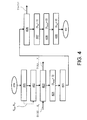
- the inventive method comprises a symbolic start step STR corresponding to a start step of a processing cycle of the PLC 10.
- the method comprises a step of determining 401 setting values for the parameters to be controlled by the PLC 10.
- step 401 is, for example, programmable, and the PLC 10 is configured to set in real time: the thresholds to be passed through; the passing-through direction of such thresholds (in an increasing or decreasing direction) by the input analog signals sent to the apparatus 100; the analog value of the outputs set by the PLC 10 during the processing cycle and the analog value to be set on the first output T1 following the passing-through event of the thresholds.
- the PLC 10 is configured to generate automatically and in deterministic terms the current values set for the function to be controlled based on the operative parameters of the industrial process.
- the method provides a step of sending 402 by the PLC 10 of the above-mentioned setting values to the secondary processing block 40 associated to the input/output electronic module 20 of the signals arranged in a distal position from the PLC 10.
- such step provides the step of providing to the secondary processing block 40 the first signal S REF indicative of the thresholds REF1,REF2 associated to the sub-group of input signals S1,S2 to be controlled, and the second signal S T1* indicative of the value T1* preset for the first control signal T1 to be outputted.
- the method further provides a step of providing to the PLC 10 the plurality of input signals S1, S2,..., Sn to generate the corresponding plurality of output control signals T1, T2,..., Tm.
- the first output T1 takes a value equal to the value T1 PLC set by the PLC 10.
- such step comprises the further step of providing 403 to the secondary processing block 40 the sub-group of the input signals, i.e., the single signal S1 or both the first S1 and the second S2 input signals.
- the method provides a step of enabling 404, by the PLC 10, the secondary processing block 40. As stated above, this occurs by enabling the third signal S ARM , for example, making so that such binary signal takes the logic value 1.
- the method provides a control start step 405 of the signals of the input sub-group S1,S2 by the secondary processing block 40 and of comparing with the corresponding thresholds REF1,REF2.
- such step 405 comprises a further changing step, by the PLC 10, of the setting values sent to the secondary processing block 40, based on the operative parameters of the industrial process, also in the enabling step of the block 40.
- the PLC 10 is configured to change the values of the thresholds REF1,REF2 associated to the sub-group of input signals S1,S2 and the value T1* preset for a first output control signal T1 to make them available to the secondary processing block 40 during the enabling step of such block.
- the secondary processing block 40 sets (step 406 of Fig. 4 ) the first output control signal T1 on the preset value T1*.
- such passing-through event is schematically illustrated by the points X of the diagrams.
- the control of the above-mentioned first output T1 is taken by the secondary processing block 40.
- the above-mentioned step 406 is implemented following the detection of the passing-through event of the first threshold REF1 by such single input signal S1.
- the step 406 is implemented based on a Boolean combination of the passing-through events of the first REF1 and of the second REF2 thresholds by the above-mentioned signals.
- the step 405 can be implemented following the passing-through of both the above-mentioned thresholds REF1, REF2 by the two input signals S1, S2, in accordance with a logic of the AND type, as shown in the Figs. 3A-3B .
- the step 405 can be implemented following the passing-through of any of the two thresholds by the relative input signal, in accordance with a logic of the OR type.
- step 406 is carried out during a second time interval or reaction time to the event Tr having a duration that is less than that of the first time interval Tc.
- second time interval has, for example, a duration of about 200 ⁇ sec.
- a jitter value JR of the reaction time Tr experimentally assessed that, as it is known, is indicative of the variability of the reaction time in diverse responses to passing-through events, is less than or equal to about 60 ⁇ sec.
- the method comprises an additional step 407 in which the secondary processing block 40 generates the fifth signal or switchover signal S SW of the binary type sent to the PLC 10.
- the secondary processing block 40 generates a switchover signal S SW that takes the logic value 1 to indicate to the PLC the occurrence of the passing-through event of the thresholds REF1, REF2 in the above described modes.
- the PLC 10 proceeds to disenable (step 408) the secondary processing block 40, particularly making so that the third binary signal S ARM takes the logic value 0.
- step 408 is implemented after a time interval of 2-3 cycle times Tc from the end of said setting step of the first output T1.
- the method ensure a rapid return to the complete control of the apparatus 100 by the PLC 10 following the passing-through event of the threshold X.
- the method further provides the step 409 in which the switchover signal S SW is brought back to the logic value 0.
- the algorithm relative to the inventive method symbolically ends with an end step ED.
- the method for controlling an industrial process and the corresponding control apparatus 100 of the present invention have many advantages.
- the apparatus 100 and the inventive method ensure a more rapid intervention following the occurrence of threshold passing-through events and, consequently, a higher accuracy in a number of operations according to what is required by the current quality standards.
- the inventive method ensures a substantially real-time programmability of the parameters involved by the PLC 10.
- the invention ensures the possibility to dynamically customize such parameters to the current values of the signals of interest, for example, pressure values relative to the above-mentioned application example.
- the proposed method allows cyclically changing the output value T1* by the PLC 10 and setting it on the secondary processing block 40. In such a manner, it is ensured that the value actually implemented by such block 40 after a passing-through of the threshold is the one calculated by the PLC 10 a few milliseconds before the event.
- the secondary processing block 40 i.e., a processing element delocalized from the PLC 10 by a bus 30, the control of the response of the apparatus 100 to the passing-through event of the threshold, avoids burdening the data exchange between the PLC and the signal input/output module 20, while allowing to use in the apparatus 100 PLCs 10 that are less efficient in terms of cycle times and, therefore, less expensive.
- Such PLCs 10 have also lower power dissipations, therefore have less stringent requirements in terms of heat dissipation. This allows, for example, to use PLCs of the fan-less type having a high reliability, and requiring less measures for heat dissipation within electric cabinets.
Priority Applications (1)
| Application Number | Priority Date | Filing Date | Title |
|---|---|---|---|
| EP13425086.9A EP2816424A1 (fr) | 2013-06-20 | 2013-06-20 | Procédé et système de contrôle d'un procédé industriel |
Applications Claiming Priority (1)
| Application Number | Priority Date | Filing Date | Title |
|---|---|---|---|
| EP13425086.9A EP2816424A1 (fr) | 2013-06-20 | 2013-06-20 | Procédé et système de contrôle d'un procédé industriel |
Publications (1)
| Publication Number | Publication Date |
|---|---|
| EP2816424A1 true EP2816424A1 (fr) | 2014-12-24 |
Family
ID=48985716
Family Applications (1)
| Application Number | Title | Priority Date | Filing Date |
|---|---|---|---|
| EP13425086.9A Withdrawn EP2816424A1 (fr) | 2013-06-20 | 2013-06-20 | Procédé et système de contrôle d'un procédé industriel |
Country Status (1)
| Country | Link |
|---|---|
| EP (1) | EP2816424A1 (fr) |
Cited By (1)
| Publication number | Priority date | Publication date | Assignee | Title |
|---|---|---|---|---|
| CN114755969A (zh) * | 2022-03-22 | 2022-07-15 | 中国第一汽车股份有限公司 | 一种通过称重与位移传感器辅助伺服电机驱动的控制方法与系统 |
Citations (4)
| Publication number | Priority date | Publication date | Assignee | Title |
|---|---|---|---|---|
| US4870614A (en) * | 1984-08-02 | 1989-09-26 | Quatse Jesse T | Programmable controller ("PC") with co-processing architecture |
| US20040133285A1 (en) * | 2002-11-02 | 2004-07-08 | Mannesmann Plastics Machinery Gmbh | Control system for a plastics processing machine |
| US20110077749A1 (en) * | 2009-09-30 | 2011-03-31 | General Electric Company | Multi-processor based programmable logic controller and method for operating the same |
| US20130090745A1 (en) * | 2011-10-05 | 2013-04-11 | Opteon Corporation | Methods and apparatus employing an action engine for monitoring and/or controlling dynamic environments |
-
2013
- 2013-06-20 EP EP13425086.9A patent/EP2816424A1/fr not_active Withdrawn
Patent Citations (4)
| Publication number | Priority date | Publication date | Assignee | Title |
|---|---|---|---|---|
| US4870614A (en) * | 1984-08-02 | 1989-09-26 | Quatse Jesse T | Programmable controller ("PC") with co-processing architecture |
| US20040133285A1 (en) * | 2002-11-02 | 2004-07-08 | Mannesmann Plastics Machinery Gmbh | Control system for a plastics processing machine |
| US20110077749A1 (en) * | 2009-09-30 | 2011-03-31 | General Electric Company | Multi-processor based programmable logic controller and method for operating the same |
| US20130090745A1 (en) * | 2011-10-05 | 2013-04-11 | Opteon Corporation | Methods and apparatus employing an action engine for monitoring and/or controlling dynamic environments |
Cited By (1)
| Publication number | Priority date | Publication date | Assignee | Title |
|---|---|---|---|---|
| CN114755969A (zh) * | 2022-03-22 | 2022-07-15 | 中国第一汽车股份有限公司 | 一种通过称重与位移传感器辅助伺服电机驱动的控制方法与系统 |
Similar Documents
| Publication | Publication Date | Title |
|---|---|---|
| US8346378B2 (en) | Programmable controller | |
| CN108572628B (zh) | 从机装置、从机装置的控制方法以及非易失性存储媒体 | |
| TWI604289B (zh) | Control system, support device, control device, and control method | |
| CN104618054A (zh) | 参数调整方法及装置 | |
| JP2019020822A (ja) | プログラマブルコントローラ | |
| US20190103293A1 (en) | System and method for manufacturing semiconductor device | |
| EP3493379A1 (fr) | Dispositif semiconducteur et son procédé de surveillance de puissance | |
| CN111142591A (zh) | 温度突变检测方法、装置及存储介质 | |
| EP2816424A1 (fr) | Procédé et système de contrôle d'un procédé industriel | |
| KR101336373B1 (ko) | 아날로그 입력 시스템, 아날로그 출력 시스템, 및 아날로그 입출력 시스템 | |
| CN111951875B (zh) | Dram内存颗粒的测试方法及装置 | |
| US20170345513A1 (en) | Method and system for implementing one-wire programmable circuit | |
| KR101593835B1 (ko) | Plc 시스템 | |
| CN106407143B (zh) | 控制移动终端中cpu的热插拔操作的方法和装置 | |
| US20150066168A1 (en) | Apparatus and method for updating operating system in programmable logic controller | |
| JP6686521B2 (ja) | 制御システムおよび制御方法 | |
| US20200195707A1 (en) | Method for transferring data from a device to a data management means, switching unit, device and system | |
| JP2011134197A (ja) | プログラマブルコントローラ、及びプログラマブルコントローラにおける複数処理の時分割方法 | |
| JP5844013B1 (ja) | 機能ユニット、アナログ入力ユニット、プログラマブルコントローラシステム | |
| US10062532B2 (en) | Method and circuit arrangement for the activation and parameterization of an electrical device | |
| CN105122158A (zh) | 具有短延迟时间的可编程控制装置 | |
| US20080126497A1 (en) | Controller Apparatus with Shared Expansion Connection and Method for the same | |
| CN112161726A (zh) | 无线温振传感器及其控制方法、计算机装置和存储介质 | |
| US10608657B2 (en) | Analog-to-digital conversion apparatus and analog-to-digital conversion method | |
| US20210132565A1 (en) | Programmable controller |
Legal Events
| Date | Code | Title | Description |
|---|---|---|---|
| PUAI | Public reference made under article 153(3) epc to a published international application that has entered the european phase |
Free format text: ORIGINAL CODE: 0009012 |
|
| 17P | Request for examination filed |
Effective date: 20130620 |
|
| AK | Designated contracting states |
Kind code of ref document: A1 Designated state(s): AL AT BE BG CH CY CZ DE DK EE ES FI FR GB GR HR HU IE IS IT LI LT LU LV MC MK MT NL NO PL PT RO RS SE SI SK SM TR |
|
| AX | Request for extension of the european patent |
Extension state: BA ME |
|
| STAA | Information on the status of an ep patent application or granted ep patent |
Free format text: STATUS: THE APPLICATION IS DEEMED TO BE WITHDRAWN |
|
| 18D | Application deemed to be withdrawn |
Effective date: 20150625 |