EP2816294A2 - Agencement de gril - Google Patents
Agencement de gril Download PDFInfo
- Publication number
- EP2816294A2 EP2816294A2 EP14172105.0A EP14172105A EP2816294A2 EP 2816294 A2 EP2816294 A2 EP 2816294A2 EP 14172105 A EP14172105 A EP 14172105A EP 2816294 A2 EP2816294 A2 EP 2816294A2
- Authority
- EP
- European Patent Office
- Prior art keywords
- vanes
- arrangement
- grill
- arrangement according
- grill arrangement
- Prior art date
- Legal status (The legal status is an assumption and is not a legal conclusion. Google has not performed a legal analysis and makes no representation as to the accuracy of the status listed.)
- Withdrawn
Links
Images


Classifications
-
- F—MECHANICAL ENGINEERING; LIGHTING; HEATING; WEAPONS; BLASTING
- F24—HEATING; RANGES; VENTILATING
- F24F—AIR-CONDITIONING; AIR-HUMIDIFICATION; VENTILATION; USE OF AIR CURRENTS FOR SCREENING
- F24F13/00—Details common to, or for air-conditioning, air-humidification, ventilation or use of air currents for screening
- F24F13/08—Air-flow control members, e.g. louvres, grilles, flaps or guide plates
- F24F13/081—Air-flow control members, e.g. louvres, grilles, flaps or guide plates for guiding air around a curve
-
- F—MECHANICAL ENGINEERING; LIGHTING; HEATING; WEAPONS; BLASTING
- F24—HEATING; RANGES; VENTILATING
- F24F—AIR-CONDITIONING; AIR-HUMIDIFICATION; VENTILATION; USE OF AIR CURRENTS FOR SCREENING
- F24F7/00—Ventilation
- F24F7/04—Ventilation with ducting systems, e.g. by double walls; with natural circulation
- F24F7/06—Ventilation with ducting systems, e.g. by double walls; with natural circulation with forced air circulation, e.g. by fan positioning of a ventilator in or against a conduit
- F24F7/08—Ventilation with ducting systems, e.g. by double walls; with natural circulation with forced air circulation, e.g. by fan positioning of a ventilator in or against a conduit with separate ducts for supplied and exhausted air with provisions for reversal of the input and output systems
-
- F—MECHANICAL ENGINEERING; LIGHTING; HEATING; WEAPONS; BLASTING
- F24—HEATING; RANGES; VENTILATING
- F24F—AIR-CONDITIONING; AIR-HUMIDIFICATION; VENTILATION; USE OF AIR CURRENTS FOR SCREENING
- F24F13/00—Details common to, or for air-conditioning, air-humidification, ventilation or use of air currents for screening
- F24F13/02—Ducting arrangements
- F24F13/06—Outlets for directing or distributing air into rooms or spaces, e.g. ceiling air diffuser
-
- F—MECHANICAL ENGINEERING; LIGHTING; HEATING; WEAPONS; BLASTING
- F24—HEATING; RANGES; VENTILATING
- F24F—AIR-CONDITIONING; AIR-HUMIDIFICATION; VENTILATION; USE OF AIR CURRENTS FOR SCREENING
- F24F13/00—Details common to, or for air-conditioning, air-humidification, ventilation or use of air currents for screening
- F24F13/08—Air-flow control members, e.g. louvres, grilles, flaps or guide plates
- F24F13/082—Grilles, registers or guards
-
- F—MECHANICAL ENGINEERING; LIGHTING; HEATING; WEAPONS; BLASTING
- F24—HEATING; RANGES; VENTILATING
- F24F—AIR-CONDITIONING; AIR-HUMIDIFICATION; VENTILATION; USE OF AIR CURRENTS FOR SCREENING
- F24F7/00—Ventilation
- F24F7/02—Roof ventilation
-
- F—MECHANICAL ENGINEERING; LIGHTING; HEATING; WEAPONS; BLASTING
- F24—HEATING; RANGES; VENTILATING
- F24F—AIR-CONDITIONING; AIR-HUMIDIFICATION; VENTILATION; USE OF AIR CURRENTS FOR SCREENING
- F24F7/00—Ventilation
- F24F2007/004—Natural ventilation using convection
-
- F—MECHANICAL ENGINEERING; LIGHTING; HEATING; WEAPONS; BLASTING
- F24—HEATING; RANGES; VENTILATING
- F24F—AIR-CONDITIONING; AIR-HUMIDIFICATION; VENTILATION; USE OF AIR CURRENTS FOR SCREENING
- F24F2221/00—Details or features not otherwise provided for
- F24F2221/28—Details or features not otherwise provided for using the Coanda effect
Definitions
- This arrangement concerns a grill arrangement for a natural ventilation system.
- a grill arrangement for a natural ventilation system the arrangement include a support structure locatable in an opening in a surface, and a plurality of spaced vanes mounted to the support structure, which vanes are curved to urge a flow of air entering the grill arrangement from outside of the surface to be turned towards a direction extending parallel to the surface.
- the grill arrangement may be configured such that air passing through the grill arrangement from outside of the surface will substantially follow the profile of the surface by virtue of the Coanda effect.
- the vanes may be curved from a direction perpendicular to the surface through an angle of between 80 and 65°, and in particular between 80 and 70°.
- the vanes may include an arcuate part, and the spacing between the arcuate parts on adjacent vanes may correspond at least generally to the radius of the arcuate parts.
- the vanes may also include a substantially tangential part at the downstream end of the arcuate parts.
- the arcuate parts may extend from four up to fifteen times the length of the tangential part.
- the tangential parts may be configured such that the space between adjacent vanes reduces at the tangential parts, and the space may reduce by an amount less than 40%.
- the radius of the arcuate parts of the vanes is typically kept unchanged across the arrangement.
- the spacing between vanes at an upstream end thereof may be between 100 and 35mm, and particularly between 75 and 40mm.
- the spacing between vanes may be constant at least for the arcuate parts thereof.
- the vanes may be configured such that there is substantially no line of sight through the arrangement.
- the vanes may be located further in a downstream direction at a first part of the arrangement relative to a second part of the arrangement.
- a line extending between downstream ends of the vanes in the first part of the arrangement to the second part of the arrangement may be inclined at an angle to the horizontal of between 5 and 15°, particularly 8 and 12°, and more particularly at an angle of substantially 10°.
- the first part of the arrangement may be towards the middle of the arrangement.
- the arrangement may also include a central section, which in one embodiment includes a section which provides direct substantially straight ventilation therethrough.
- the central section is closed, and may include an upstream pointing projection to direct air around the central section, which projection may be in the form of a four sided pyramid.
- the arrangement includes one set of vanes extending from one side which constitutes the first part, to an opposite side which constitutes the second part.
- two sets of vanes are provided each extending from opposite sides of an apex, which apex constitutes the first part.
- a third embodiment four sets of vanes are provided each extending to a respective side from an at least generally central first part.
- the invention further provides a natural ventilation arrangement, the arrangement including a grill arrangement according to any of the preceding fifteen paragraphs
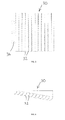
- Figs. 1 and 2 show a first grill arrangement 10 suitable for use in a natural ventilation system.
- the arrangement 10 is square in plan view and comprises four sections 12 each comprising six vanes 14 as shown in Fig. 2 .
- the vanes 14 curve outwardly and have a first arcuate portion 16 and an outer tangential portion 18.
- the vanes 14 are located sequentially downwardly towards the centre 20 of the arrangement 10.
- the vanes 14 in the arcuate portion 16 are equispaced from each other and for instance have a spacing of 50mm.
- the gap between the vanes reduces in size with the tangential portions 18, causing air to be accelerated therethrough.
- the angle of a line connecting the top of the arcuate portions relative to the horizontal is 10°.
- FIGs. 3 and 4 show a second grill arrangement 22 which is similar to the arrangement 10 but only includes two sections 24 which are divided by a central apex 26. Each of the sections 24 again includes vanes 14 potentially producing an air flow in two directions as shown by the arrows 28.
- Figs. 5 and 6 show a third grill arrangement 30 with just a single section with twelve vanes 32.
- the vanes are curved to the left as shown, and also are mounted on a line inclined upwardly at 10° to the horizontal tos at the left hand side. This causes air to flow in a single direction as shown by the arrows 34.
- Fig. 7 shows a natural ventilation arrangement 36 incorporating a fourth grill arrangement 38.
- the natural ventilation arrangement 36 is mounted on the roof of a building with a hollow cylindrical or square section body 42 which extends through the roof 40, and has a plurality of adjustable paddles 44 at a lower end thereof immediately above the grill arrangement 38 to adjust air flow therethrough.
- a cruciform divider 46 is provided within the body 40, and a plurality of louvres 48 are provided in an upper part of the body 40 to permit air to pass into or out of the body 42.
- air will pass into one or two of the portions formed by the cruciform 46 within the body 40 as shown by the arrow 50. Air will be caused to exit from the opposite one or two portions formed by the cruciform 46 within the body 40, as shown by the arrow 52.
- FIG. 8 illustrates the passage of air into and out of a similar grill arrangement 56, but has a smaller number of vanes 58.
- Fig. 9 illustrates air flow through the third grill arrangement 30 which just has a single section of vanes 32. As can be seen air entering through a gap in a wall 60 is turned to the left so as to tend to follow the underside of the wall 60 by virtue of the coanda effect.
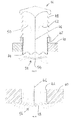
- Fig. 10 shows in more detail four vanes 62 in a grill arrangement according to the arrangement.
- Each of the vanes has an arcuate section 64 which has a radius approximately equal to the spacing between adjacent vanes 62.
- Each of the vanes 62 also has a tangential section 66 at their downstream ends, such that the spacing between the vanes 62 at their lower ends decreases causing accelleration of air passing therethrough.
- the vanes 62 are sequentially spaced downwardly towards a first part which may be a central part of a grill arrangement such as shown in the grill arrangements 10 and 22.
- Lines illustrate the angle 68 by which the vanes 62 are spaced upwardly from the first part.
- the spacing between the vanes 62 is 50mm and hence the radius of the arcuate part 64 is also 50mm.
- the angle 68 is 10°.
- Figs. 12 and 13 shows a fifth grill arrangement 70 which could be suitable for instance with a natural ventilator which has a hybrid arrangement, including for example a central fan which may be solar operated, and operable as required, and particularly where there is not sufficient wind to produce natural ventilation.
- a natural ventilator which has a hybrid arrangement, including for example a central fan which may be solar operated, and operable as required, and particularly where there is not sufficient wind to produce natural ventilation.
- the fifth grill arrangement 70 is generally similar to the first grill arrangement 10 except that a central section 72 is provided without any vanes, which permits direct vertical ventilation and will connect to for instance the solar powered fan. Illustrated by broken lines are modular extensions 74 on all four sides of the grill arrangement 70, for use in a location where a larger grill arrangement is required.
- thermal jets may be cooler than the ambient temperature, and this arrangement will provide a longer time for thermal jets to be heated up by their surroundings.
- vanes may have a different profile, and a different number or spacing of vanes may be used.
- the angle of the vanes relative to a horizontal alignment can be varied.
- Different configurations and vanes and/or other grill parts can be provided.
- the grill arrangement may have a number of different shapes such as square, rectangular or circular, with correspondingly shaped vane configurations.
Applications Claiming Priority (1)
| Application Number | Priority Date | Filing Date | Title |
|---|---|---|---|
| GB1310814.7A GB2511148B (en) | 2013-06-18 | 2013-06-18 | Grill arrangement |
Publications (2)
| Publication Number | Publication Date |
|---|---|
| EP2816294A2 true EP2816294A2 (fr) | 2014-12-24 |
| EP2816294A3 EP2816294A3 (fr) | 2015-07-22 |
Family
ID=48914723
Family Applications (1)
| Application Number | Title | Priority Date | Filing Date |
|---|---|---|---|
| EP14172105.0A Withdrawn EP2816294A3 (fr) | 2013-06-18 | 2014-06-12 | Agencement de gril |
Country Status (2)
| Country | Link |
|---|---|
| EP (1) | EP2816294A3 (fr) |
| GB (1) | GB2511148B (fr) |
Cited By (1)
| Publication number | Priority date | Publication date | Assignee | Title |
|---|---|---|---|---|
| CN110325799A (zh) * | 2017-02-22 | 2019-10-11 | 艾尔马斯特有限公司 | 通风装置 |
Families Citing this family (1)
| Publication number | Priority date | Publication date | Assignee | Title |
|---|---|---|---|---|
| WO2021107793A1 (fr) * | 2019-11-27 | 2021-06-03 | Jerzy Hawranek | Amplificateur de ventilation hybride |
Family Cites Families (19)
| Publication number | Priority date | Publication date | Assignee | Title |
|---|---|---|---|---|
| US2735352A (en) * | 1956-02-21 | Demuth | ||
| US2240617A (en) * | 1939-02-08 | 1941-05-06 | Air Devices Inc | Air distributor |
| US3110242A (en) * | 1953-09-21 | 1963-11-12 | Cortland N O'day | Removable core air diffusers |
| US2977869A (en) * | 1953-09-21 | 1961-04-04 | Cortland N O'day | Removable core air diffusers |
| US3391629A (en) * | 1966-07-18 | 1968-07-09 | Us Register Company | Reversible floor mounted register |
| DE7820323U1 (de) * | 1978-07-06 | 1978-10-19 | Gebrueder Trox Gmbh, 4133 Neukirchen- Vluyn | Deckenluftauslass fuer klimaanlagen |
| US4665806A (en) * | 1985-09-12 | 1987-05-19 | Martin Sr Lendell | Ventilating air distributor |
| GB2221530B (en) * | 1988-08-02 | 1992-04-15 | Hunter International Plc | Improvements in or relating to an air diffuser |
| US5338256A (en) * | 1991-12-31 | 1994-08-16 | Anthony Tonna | Ventilator |
| US5261857A (en) * | 1992-06-23 | 1993-11-16 | Bart Petterson | Ceiling vent with movable vane |
| GB2273348B (en) * | 1992-12-03 | 1997-05-14 | Hunter Technical Dev Ltd | Heating,ventilating and air-conditioning systems |
| JP3533585B2 (ja) * | 1995-03-08 | 2004-05-31 | オーケー器材株式会社 | 汚染防止型吹出口 |
| US6010402A (en) * | 1997-09-15 | 2000-01-04 | E.H. Price Limited | Air diffusers and deflector structure therefor |
| GB2362707A (en) * | 2000-05-25 | 2001-11-28 | Zetaflow Ltd | A ventilation diffuser unit |
| US20090130970A1 (en) * | 2007-11-21 | 2009-05-21 | Corey Scott Jacak | Exhaust fan and method of operating the same |
| SE533713C2 (sv) * | 2009-04-06 | 2010-12-07 | Inventiair Ab | Tilluftsdon |
| JP5456402B2 (ja) * | 2009-07-27 | 2014-03-26 | 三洋電機株式会社 | 天井埋込型空気調和装置 |
| CN201819361U (zh) * | 2010-08-11 | 2011-05-04 | 宁波翔博机械有限公司 | 一种空调通风口 |
| CN201811398U (zh) * | 2010-08-11 | 2011-04-27 | 宁波翔博机械有限公司 | 一种弧面叶片空调通风口 |
-
2013
- 2013-06-18 GB GB1310814.7A patent/GB2511148B/en not_active Expired - Fee Related
-
2014
- 2014-06-12 EP EP14172105.0A patent/EP2816294A3/fr not_active Withdrawn
Non-Patent Citations (1)
| Title |
|---|
| None * |
Cited By (2)
| Publication number | Priority date | Publication date | Assignee | Title |
|---|---|---|---|---|
| CN110325799A (zh) * | 2017-02-22 | 2019-10-11 | 艾尔马斯特有限公司 | 通风装置 |
| CN110325799B (zh) * | 2017-02-22 | 2021-05-11 | 艾尔马斯特有限公司 | 通风装置 |
Also Published As
| Publication number | Publication date |
|---|---|
| GB201310814D0 (en) | 2013-07-31 |
| GB2511148A (en) | 2014-08-27 |
| EP2816294A3 (fr) | 2015-07-22 |
| GB2511148B (en) | 2017-11-15 |
Similar Documents
| Publication | Publication Date | Title |
|---|---|---|
| US10471482B2 (en) | Exhaust apparatus, system, and method for enhanced capture and containment | |
| EP2982909B1 (fr) | Capot pour un système de ventilation | |
| RU2733158C2 (ru) | Вентилятор | |
| US20100291859A1 (en) | Ventilating device for providing a zone of clean air. | |
| EP2157305A3 (fr) | Turbine à gaz avec tuyère variable de la soufflante | |
| CN102374625A (zh) | 诱导吹出口 | |
| CN102109206B (zh) | 可生成正、负气压的风力驱动通风机 | |
| US20160161134A1 (en) | Ventilator | |
| EP2816294A2 (fr) | Agencement de gril | |
| CN109028429A (zh) | 一种适用于高大空间建筑的涡旋通风系统及方法 | |
| CN110425717A (zh) | 一种棚类建筑用于bim碰撞管道检查的“一替多”风口装置 | |
| CN204100391U (zh) | 空调器的室内机及空调器 | |
| CN105805837A (zh) | 一种壁挂式空调 | |
| KR101801193B1 (ko) | 천장부착형 공기 순환기 | |
| CN206803444U (zh) | 送风组件和空气处理系统 | |
| CN105864891A (zh) | 一种壁挂式空调 | |
| RU2592035C1 (ru) | Система вентиляции пассажирского вагона | |
| CN205014560U (zh) | 一种蜗舌装置及包括该蜗舌装置的空调器 | |
| CN205747166U (zh) | 一种壁挂式空调 | |
| EP3222928B1 (fr) | Dispositif de ventilation | |
| ES2918952T3 (es) | Sistemas y métodos de protección contra incendios para campanas de ventilación | |
| CN204880375U (zh) | 空调机 | |
| AU2014271273B2 (en) | Exhaust apparatus, system, and method for enhanced capture and containment | |
| WO2017111699A1 (fr) | Procédé et appareil de distribution et de confinement d'air dans un environnement ouvert | |
| EP2775223B1 (fr) | Buse d'alimentation d'air |
Legal Events
| Date | Code | Title | Description |
|---|---|---|---|
| PUAI | Public reference made under article 153(3) epc to a published international application that has entered the european phase |
Free format text: ORIGINAL CODE: 0009012 |
|
| 17P | Request for examination filed |
Effective date: 20140612 |
|
| AK | Designated contracting states |
Kind code of ref document: A2 Designated state(s): AL AT BE BG CH CY CZ DE DK EE ES FI FR GB GR HR HU IE IS IT LI LT LU LV MC MK MT NL NO PL PT RO RS SE SI SK SM TR |
|
| AX | Request for extension of the european patent |
Extension state: BA ME |
|
| PUAL | Search report despatched |
Free format text: ORIGINAL CODE: 0009013 |
|
| AK | Designated contracting states |
Kind code of ref document: A3 Designated state(s): AL AT BE BG CH CY CZ DE DK EE ES FI FR GB GR HR HU IE IS IT LI LT LU LV MC MK MT NL NO PL PT RO RS SE SI SK SM TR |
|
| AX | Request for extension of the european patent |
Extension state: BA ME |
|
| RIC1 | Information provided on ipc code assigned before grant |
Ipc: F24F 7/08 20060101ALI20150612BHEP Ipc: F24F 13/08 20060101ALI20150612BHEP Ipc: F24F 13/06 20060101ALI20150612BHEP Ipc: F24F 7/02 20060101AFI20150612BHEP |
|
| R17P | Request for examination filed (corrected) |
Effective date: 20160111 |
|
| RBV | Designated contracting states (corrected) |
Designated state(s): AL AT BE BG CH CY CZ DE DK EE ES FI FR GB GR HR HU IE IS IT LI LT LU LV MC MK MT NL NO PL PT RO RS SE SI SK SM TR |
|
| 17Q | First examination report despatched |
Effective date: 20190506 |
|
| STAA | Information on the status of an ep patent application or granted ep patent |
Free format text: STATUS: THE APPLICATION IS DEEMED TO BE WITHDRAWN |
|
| 18D | Application deemed to be withdrawn |
Effective date: 20191119 |