EP2816294A2 - Grill arrangement - Google Patents
Grill arrangement Download PDFInfo
- Publication number
- EP2816294A2 EP2816294A2 EP14172105.0A EP14172105A EP2816294A2 EP 2816294 A2 EP2816294 A2 EP 2816294A2 EP 14172105 A EP14172105 A EP 14172105A EP 2816294 A2 EP2816294 A2 EP 2816294A2
- Authority
- EP
- European Patent Office
- Prior art keywords
- vanes
- arrangement
- grill
- arrangement according
- grill arrangement
- Prior art date
- Legal status (The legal status is an assumption and is not a legal conclusion. Google has not performed a legal analysis and makes no representation as to the accuracy of the status listed.)
- Withdrawn
Links
Images


Classifications
-
- F—MECHANICAL ENGINEERING; LIGHTING; HEATING; WEAPONS; BLASTING
- F24—HEATING; RANGES; VENTILATING
- F24F—AIR-CONDITIONING; AIR-HUMIDIFICATION; VENTILATION; USE OF AIR CURRENTS FOR SCREENING
- F24F13/00—Details common to, or for air-conditioning, air-humidification, ventilation or use of air currents for screening
- F24F13/08—Air-flow control members, e.g. louvres, grilles, flaps or guide plates
- F24F13/081—Air-flow control members, e.g. louvres, grilles, flaps or guide plates for guiding air around a curve
-
- F—MECHANICAL ENGINEERING; LIGHTING; HEATING; WEAPONS; BLASTING
- F24—HEATING; RANGES; VENTILATING
- F24F—AIR-CONDITIONING; AIR-HUMIDIFICATION; VENTILATION; USE OF AIR CURRENTS FOR SCREENING
- F24F7/00—Ventilation
- F24F7/04—Ventilation with ducting systems, e.g. by double walls; with natural circulation
- F24F7/06—Ventilation with ducting systems, e.g. by double walls; with natural circulation with forced air circulation, e.g. by fan positioning of a ventilator in or against a conduit
- F24F7/08—Ventilation with ducting systems, e.g. by double walls; with natural circulation with forced air circulation, e.g. by fan positioning of a ventilator in or against a conduit with separate ducts for supplied and exhausted air with provisions for reversal of the input and output systems
-
- F—MECHANICAL ENGINEERING; LIGHTING; HEATING; WEAPONS; BLASTING
- F24—HEATING; RANGES; VENTILATING
- F24F—AIR-CONDITIONING; AIR-HUMIDIFICATION; VENTILATION; USE OF AIR CURRENTS FOR SCREENING
- F24F13/00—Details common to, or for air-conditioning, air-humidification, ventilation or use of air currents for screening
- F24F13/02—Ducting arrangements
- F24F13/06—Outlets for directing or distributing air into rooms or spaces, e.g. ceiling air diffuser
-
- F—MECHANICAL ENGINEERING; LIGHTING; HEATING; WEAPONS; BLASTING
- F24—HEATING; RANGES; VENTILATING
- F24F—AIR-CONDITIONING; AIR-HUMIDIFICATION; VENTILATION; USE OF AIR CURRENTS FOR SCREENING
- F24F13/00—Details common to, or for air-conditioning, air-humidification, ventilation or use of air currents for screening
- F24F13/08—Air-flow control members, e.g. louvres, grilles, flaps or guide plates
- F24F13/082—Grilles, registers or guards
-
- F—MECHANICAL ENGINEERING; LIGHTING; HEATING; WEAPONS; BLASTING
- F24—HEATING; RANGES; VENTILATING
- F24F—AIR-CONDITIONING; AIR-HUMIDIFICATION; VENTILATION; USE OF AIR CURRENTS FOR SCREENING
- F24F7/00—Ventilation
- F24F7/02—Roof ventilation
-
- F—MECHANICAL ENGINEERING; LIGHTING; HEATING; WEAPONS; BLASTING
- F24—HEATING; RANGES; VENTILATING
- F24F—AIR-CONDITIONING; AIR-HUMIDIFICATION; VENTILATION; USE OF AIR CURRENTS FOR SCREENING
- F24F7/00—Ventilation
- F24F2007/004—Natural ventilation using convection
-
- F—MECHANICAL ENGINEERING; LIGHTING; HEATING; WEAPONS; BLASTING
- F24—HEATING; RANGES; VENTILATING
- F24F—AIR-CONDITIONING; AIR-HUMIDIFICATION; VENTILATION; USE OF AIR CURRENTS FOR SCREENING
- F24F2221/00—Details or features not otherwise provided for
- F24F2221/28—Details or features not otherwise provided for using the Coanda effect
Definitions
- This arrangement concerns a grill arrangement for a natural ventilation system.
- a grill arrangement for a natural ventilation system the arrangement include a support structure locatable in an opening in a surface, and a plurality of spaced vanes mounted to the support structure, which vanes are curved to urge a flow of air entering the grill arrangement from outside of the surface to be turned towards a direction extending parallel to the surface.
- the grill arrangement may be configured such that air passing through the grill arrangement from outside of the surface will substantially follow the profile of the surface by virtue of the Coanda effect.
- the vanes may be curved from a direction perpendicular to the surface through an angle of between 80 and 65°, and in particular between 80 and 70°.
- the vanes may include an arcuate part, and the spacing between the arcuate parts on adjacent vanes may correspond at least generally to the radius of the arcuate parts.
- the vanes may also include a substantially tangential part at the downstream end of the arcuate parts.
- the arcuate parts may extend from four up to fifteen times the length of the tangential part.
- the tangential parts may be configured such that the space between adjacent vanes reduces at the tangential parts, and the space may reduce by an amount less than 40%.
- the radius of the arcuate parts of the vanes is typically kept unchanged across the arrangement.
- the spacing between vanes at an upstream end thereof may be between 100 and 35mm, and particularly between 75 and 40mm.
- the spacing between vanes may be constant at least for the arcuate parts thereof.
- the vanes may be configured such that there is substantially no line of sight through the arrangement.
- the vanes may be located further in a downstream direction at a first part of the arrangement relative to a second part of the arrangement.
- a line extending between downstream ends of the vanes in the first part of the arrangement to the second part of the arrangement may be inclined at an angle to the horizontal of between 5 and 15°, particularly 8 and 12°, and more particularly at an angle of substantially 10°.
- the first part of the arrangement may be towards the middle of the arrangement.
- the arrangement may also include a central section, which in one embodiment includes a section which provides direct substantially straight ventilation therethrough.
- the central section is closed, and may include an upstream pointing projection to direct air around the central section, which projection may be in the form of a four sided pyramid.
- the arrangement includes one set of vanes extending from one side which constitutes the first part, to an opposite side which constitutes the second part.
- two sets of vanes are provided each extending from opposite sides of an apex, which apex constitutes the first part.
- a third embodiment four sets of vanes are provided each extending to a respective side from an at least generally central first part.
- the invention further provides a natural ventilation arrangement, the arrangement including a grill arrangement according to any of the preceding fifteen paragraphs
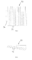
- Figs. 1 and 2 show a first grill arrangement 10 suitable for use in a natural ventilation system.
- the arrangement 10 is square in plan view and comprises four sections 12 each comprising six vanes 14 as shown in Fig. 2 .
- the vanes 14 curve outwardly and have a first arcuate portion 16 and an outer tangential portion 18.
- the vanes 14 are located sequentially downwardly towards the centre 20 of the arrangement 10.
- the vanes 14 in the arcuate portion 16 are equispaced from each other and for instance have a spacing of 50mm.
- the gap between the vanes reduces in size with the tangential portions 18, causing air to be accelerated therethrough.
- the angle of a line connecting the top of the arcuate portions relative to the horizontal is 10°.
- FIGs. 3 and 4 show a second grill arrangement 22 which is similar to the arrangement 10 but only includes two sections 24 which are divided by a central apex 26. Each of the sections 24 again includes vanes 14 potentially producing an air flow in two directions as shown by the arrows 28.
- Figs. 5 and 6 show a third grill arrangement 30 with just a single section with twelve vanes 32.
- the vanes are curved to the left as shown, and also are mounted on a line inclined upwardly at 10° to the horizontal tos at the left hand side. This causes air to flow in a single direction as shown by the arrows 34.
- Fig. 7 shows a natural ventilation arrangement 36 incorporating a fourth grill arrangement 38.
- the natural ventilation arrangement 36 is mounted on the roof of a building with a hollow cylindrical or square section body 42 which extends through the roof 40, and has a plurality of adjustable paddles 44 at a lower end thereof immediately above the grill arrangement 38 to adjust air flow therethrough.
- a cruciform divider 46 is provided within the body 40, and a plurality of louvres 48 are provided in an upper part of the body 40 to permit air to pass into or out of the body 42.
- air will pass into one or two of the portions formed by the cruciform 46 within the body 40 as shown by the arrow 50. Air will be caused to exit from the opposite one or two portions formed by the cruciform 46 within the body 40, as shown by the arrow 52.
- FIG. 8 illustrates the passage of air into and out of a similar grill arrangement 56, but has a smaller number of vanes 58.
- Fig. 9 illustrates air flow through the third grill arrangement 30 which just has a single section of vanes 32. As can be seen air entering through a gap in a wall 60 is turned to the left so as to tend to follow the underside of the wall 60 by virtue of the coanda effect.
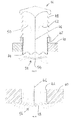
- Fig. 10 shows in more detail four vanes 62 in a grill arrangement according to the arrangement.
- Each of the vanes has an arcuate section 64 which has a radius approximately equal to the spacing between adjacent vanes 62.
- Each of the vanes 62 also has a tangential section 66 at their downstream ends, such that the spacing between the vanes 62 at their lower ends decreases causing accelleration of air passing therethrough.
- the vanes 62 are sequentially spaced downwardly towards a first part which may be a central part of a grill arrangement such as shown in the grill arrangements 10 and 22.
- Lines illustrate the angle 68 by which the vanes 62 are spaced upwardly from the first part.
- the spacing between the vanes 62 is 50mm and hence the radius of the arcuate part 64 is also 50mm.
- the angle 68 is 10°.
- Figs. 12 and 13 shows a fifth grill arrangement 70 which could be suitable for instance with a natural ventilator which has a hybrid arrangement, including for example a central fan which may be solar operated, and operable as required, and particularly where there is not sufficient wind to produce natural ventilation.
- a natural ventilator which has a hybrid arrangement, including for example a central fan which may be solar operated, and operable as required, and particularly where there is not sufficient wind to produce natural ventilation.
- the fifth grill arrangement 70 is generally similar to the first grill arrangement 10 except that a central section 72 is provided without any vanes, which permits direct vertical ventilation and will connect to for instance the solar powered fan. Illustrated by broken lines are modular extensions 74 on all four sides of the grill arrangement 70, for use in a location where a larger grill arrangement is required.
- thermal jets may be cooler than the ambient temperature, and this arrangement will provide a longer time for thermal jets to be heated up by their surroundings.
- vanes may have a different profile, and a different number or spacing of vanes may be used.
- the angle of the vanes relative to a horizontal alignment can be varied.
- Different configurations and vanes and/or other grill parts can be provided.
- the grill arrangement may have a number of different shapes such as square, rectangular or circular, with correspondingly shaped vane configurations.
Abstract
Description
- This arrangement concerns a grill arrangement for a natural ventilation system.
- With natural ventilation which may be wind driven, and may be hybrid and include for instance an optional powered system, a generally much lower pressure potential is available than in mechanical air supply systems. Accordingly in a grill arrangement it is important not to encounter a significant loss of pressure. Therefore generally in such applications a very simple grill is used. Such grills may often result in low ventilation efficiency and inadequate comfort due to cold air reaching a living space or other directly from a ventilation outlet.
- According to the present invention there is provided a grill arrangement for a natural ventilation system, the arrangement include a support structure locatable in an opening in a surface, and a plurality of spaced vanes mounted to the support structure, which vanes are curved to urge a flow of air entering the grill arrangement from outside of the surface to be turned towards a direction extending parallel to the surface.
- The grill arrangement may be configured such that air passing through the grill arrangement from outside of the surface will substantially follow the profile of the surface by virtue of the Coanda effect.
- The vanes may be curved from a direction perpendicular to the surface through an angle of between 80 and 65°, and in particular between 80 and 70°.
- The vanes may include an arcuate part, and the spacing between the arcuate parts on adjacent vanes may correspond at least generally to the radius of the arcuate parts.
- The vanes may also include a substantially tangential part at the downstream end of the arcuate parts. The arcuate parts may extend from four up to fifteen times the length of the tangential part.
- The tangential parts may be configured such that the space between adjacent vanes reduces at the tangential parts, and the space may reduce by an amount less than 40%.
- The radius of the arcuate parts of the vanes is typically kept unchanged across the arrangement.
- The spacing between vanes at an upstream end thereof may be between 100 and 35mm, and particularly between 75 and 40mm. The spacing between vanes may be constant at least for the arcuate parts thereof.
- The vanes may be configured such that there is substantially no line of sight through the arrangement.
- The vanes may be located further in a downstream direction at a first part of the arrangement relative to a second part of the arrangement. A line extending between downstream ends of the vanes in the first part of the arrangement to the second part of the arrangement may be inclined at an angle to the horizontal of between 5 and 15°, particularly 8 and 12°, and more particularly at an angle of substantially 10°.
- The first part of the arrangement may be towards the middle of the arrangement.
- The arrangement may also include a central section, which in one embodiment includes a section which provides direct substantially straight ventilation therethrough. In a further embodiment the central section is closed, and may include an upstream pointing projection to direct air around the central section, which projection may be in the form of a four sided pyramid.
- In a first configuration the arrangement includes one set of vanes extending from one side which constitutes the first part, to an opposite side which constitutes the second part.
- In a second configuration two sets of vanes are provided each extending from opposite sides of an apex, which apex constitutes the first part.
- In a third embodiment four sets of vanes are provided each extending to a respective side from an at least generally central first part.
- The invention further provides a natural ventilation arrangement, the arrangement including a grill arrangement according to any of the preceding fifteen paragraphs
- Embodiments of the present invention will now be described by way of example only and with reference to the accompanying drawings, in which:-
-
Fig. 1 is a diagrammatic view from beneath of a first grill arrangement according to the invention; -
Fig. 2 is a cross sectional view of the arrangement ofFig. 1 ; -
Figs. 3 and 4 are similar views respectively toFigs. 1 and 2 but of a second grill arrangement according to the invention; -
Figs. 5 and 6 are similar views toFigs. 1 and 2 but of a third grill arrangement according to the invention; -
Fig. 7 is a diagrammatic cross sectional view of a natural ventilation arrangement incorporating a fourth grill arrangement according to the present invention; -
Fig. 8 is a diagrammatic cross sectional view through a lower part of the apparatus ofFig. 7 but incorporating a different grill arrangement; -
Fig. 9 is a similar view toFig. 8 , and is a diagrammatic view showing operation of the third grill arrangement in use according to the invention; -
Fig. 10 is a cross sectional detailed view through part of a grill arrangement according to the invention; -
Fig. 11 is a diagrammatic view showing operation of part of a grill arrangement according to the invention; -
Fig. 12 is a diagrammatic view from beneath of a fifth grill arrangement according to the invention; and -
Fig. 13 is a diagrammatic cross sectional view through part of the grill arrangement ofFig. 12 . -
Figs. 1 and 2 show afirst grill arrangement 10 suitable for use in a natural ventilation system. Thearrangement 10 is square in plan view and comprises foursections 12 each comprising sixvanes 14 as shown inFig. 2 . Thevanes 14 curve outwardly and have a firstarcuate portion 16 and an outertangential portion 18. Thevanes 14 are located sequentially downwardly towards the centre 20 of thearrangement 10. - The
vanes 14 in thearcuate portion 16 are equispaced from each other and for instance have a spacing of 50mm. The gap between the vanes reduces in size with thetangential portions 18, causing air to be accelerated therethrough. The angle of a line connecting the top of the arcuate portions relative to the horizontal is 10°. - In practice air will flow downwardly through the
arrangement 10 and outwardly as shown by thearrows 21 and illustrated for instance inFig. 11 . Positive pressure on the vanes is indicated by a plus symbol, and negative pressure along the air jet is indicated by a minus symbol. The air passes between thevanes 14 and is accelerated out thereof by virtue of the reduced spacing between thetangential portions 18. By virtue of the shape of the vanes the air jet is turned towards a direction extending parallel to a ceiling or wall surrounding thearrangement 10 and by virtue of a Coanda effect. This will tend to attach to these surfaces and spread further into the space. Air from the space below thearrangement 10 is dragged in to the supplied air due to the pressure conditions formed along the moving jet. -
Figs. 3 and 4 show asecond grill arrangement 22 which is similar to thearrangement 10 but only includes twosections 24 which are divided by acentral apex 26. Each of thesections 24 again includesvanes 14 potentially producing an air flow in two directions as shown by thearrows 28. -
Figs. 5 and 6 show athird grill arrangement 30 with just a single section with twelvevanes 32. As can be seen fromFig. 6 the vanes are curved to the left as shown, and also are mounted on a line inclined upwardly at 10° to the horizontal tos at the left hand side. This causes air to flow in a single direction as shown by thearrows 34. -
Fig. 7 shows anatural ventilation arrangement 36 incorporating afourth grill arrangement 38. Thenatural ventilation arrangement 36 is mounted on the roof of a building with a hollow cylindrical orsquare section body 42 which extends through theroof 40, and has a plurality ofadjustable paddles 44 at a lower end thereof immediately above thegrill arrangement 38 to adjust air flow therethrough. - A
cruciform divider 46 is provided within thebody 40, and a plurality oflouvres 48 are provided in an upper part of thebody 40 to permit air to pass into or out of thebody 42. By virtue of the wind direction air will pass into one or two of the portions formed by thecruciform 46 within thebody 40 as shown by thearrow 50. Air will be caused to exit from the opposite one or two portions formed by thecruciform 46 within thebody 40, as shown by the arrow 52. - Air passing downwardly through the
ventilation arrangement 36 and hencegrill arrangement 38 will tend to follow the underside of theroof 40 by virtue of the Coanda effect as described above. An upwardly extendingprojection 54 is provided at the centre of thegrill arrangement 38 to separate air passing into the building from air passing out thereof.Fig. 8 illustrates the passage of air into and out of asimilar grill arrangement 56, but has a smaller number ofvanes 58. -
Fig. 9 illustrates air flow through thethird grill arrangement 30 which just has a single section ofvanes 32. As can be seen air entering through a gap in awall 60 is turned to the left so as to tend to follow the underside of thewall 60 by virtue of the coanda effect. -
Fig. 10 shows in more detail fourvanes 62 in a grill arrangement according to the arrangement. Each of the vanes has anarcuate section 64 which has a radius approximately equal to the spacing betweenadjacent vanes 62. Each of thevanes 62 also has atangential section 66 at their downstream ends, such that the spacing between thevanes 62 at their lower ends decreases causing accelleration of air passing therethrough. - The
vanes 62 are sequentially spaced downwardly towards a first part which may be a central part of a grill arrangement such as shown in thegrill arrangements angle 68 by which thevanes 62 are spaced upwardly from the first part. In the example shown inFig. 10 the spacing between thevanes 62 is 50mm and hence the radius of thearcuate part 64 is also 50mm. Theangle 68 is 10°. -
Figs. 12 and 13 shows afifth grill arrangement 70 which could be suitable for instance with a natural ventilator which has a hybrid arrangement, including for example a central fan which may be solar operated, and operable as required, and particularly where there is not sufficient wind to produce natural ventilation. - The
fifth grill arrangement 70 is generally similar to thefirst grill arrangement 10 except that acentral section 72 is provided without any vanes, which permits direct vertical ventilation and will connect to for instance the solar powered fan. Illustrated by broken lines aremodular extensions 74 on all four sides of thegrill arrangement 70, for use in a location where a larger grill arrangement is required. - There are thus described a number of arrangements which by using the Coanda effect permit ventilation air to move essentially across a ceiling rather than directly down into a room. This helps to enhance ventilation efficiency by generally achieving a greater distance travelled for the ventilated air. This thus means that the same size of natural ventilation arrangement can be used for a larger room than would otherwise be the case with a conventional grill arrangement.
- In conventional arrangements air will tend to bounce of the floor tending to mean that dirt will be picked up. In contrast, with grill arrangements according to the invention air will be delivered through a cleaner route to an occupied zone, rather than being bounced off a potentially dirty floor. In winter thermal jets may be cooler than the ambient temperature, and this arrangement will provide a longer time for thermal jets to be heated up by their surroundings.
- With the arrangements described above there is essentially no line of sight which is aesthetically more pleasing and will tend to reduce noise penetration from roof level. As indicated modular arrangements may be possible, and a required number of vanes may be provided in different situations.
- It is to be realised that various other modifications may be made without departing from the scope of the invention. For instance the vanes may have a different profile, and a different number or spacing of vanes may be used. The angle of the vanes relative to a horizontal alignment can be varied. Different configurations and vanes and/or other grill parts can be provided. The grill arrangement may have a number of different shapes such as square, rectangular or circular, with correspondingly shaped vane configurations.
- Whilst endeavouring in the foregoing specification to draw attention to those features of the invention believed to be of particular importance it should be understood that the Applicant claims protection in respect of any patentable feature or combination of features hereinbefore referred to and/or shown in the drawings whether or not particular emphasis has been placed thereon.
Claims (15)
- A grill arrangement for a natural ventilation system, the arrangement include a support structure locatable in an opening in a surface, and a plurality of spaced vanes mounted to the support structure, which vanes are curved to urge a flow of air entering the grill arrangement from outside of the surface to be turned towards a direction extending parallel to the surface.
- A grill arrangement according to claim 1, in which the grill arrangement is configured such that air passing through the grill arrangement from outside of the surface will substantially follow the profile of the surface by virtue of the Coanda effect.
- A grill arrangement according to claims 1 or 2, in which the vanes may be curved from a direction perpendicular to the surface through an angle of between 80 and 65°, and more particularly between 80 and 70°.
- A grill arrangement according to any of the preceding claims, in which the vanes include an arcuate part, and the spacing between the arcuate parts on adjacent vanes may correspond at least generally to the radius of the arcuate parts.
- A grill arrangement according to claim 4, in which the vanes also include a substantially tangential part at the downstream end of the arcuate parts, the arcuate parts may extend from four up to fifteen times the length of the tangential part, the tangential parts may be configured such that the space between adjacent vanes reduces at the tangential parts, and the tangential parts may be configured such that the space between adjacent vanes reduces by an amount less than 40%.
- A grill arrangement according to claims 4 or 5, in which the radius of the arcuate parts of the vanes is kept unchanged across the arrangement.
- A grill arrangement according to any of the preceding claims, in which the spacing between vanes at an upstream end thereof is between 100 and 35mm, and more particularly between 75 and 40mm.
- A grill arrangement according to claim 4, or any of claims 5 to 7 when dependent on claim 4, in which the spacing between vanes is constant at least for the arcuate parts thereof.
- A grill arrangement according to any of the preceding claims, in which the vanes are configured such that there is substantially no line of sight through the arrangement.
- A grill arrangement according to any of the preceding claims, in which the vanes are located further in a downstream direction at a first part of the arrangement relative to a second part of the arrangement, and a line extending between downstream ends of the vanes in the first part of the arrangement to the second part of the arrangement is inclined at an angle to the horizontal of between 5 and 15°, more particularly between 8 and 12°, may be substantially 10°, and the first part of the arrangement may be towards the middle of the arrangement.
- A grill arrangement according to any of the preceding claims, in which the arrangement also includes a central section, which provides direct substantially straight ventilation therethrough.
- A grill arrangement according to any of claims 1 to 10, in which the arrangement also includes a central section, which central section is closed, and the central section may include an upstream pointing projection to direct air around the central section, and the upstream pointing projection may be in the form of a four sided pyramid.
- A grill arrangement according to claim 10, or claims 11 or 12 when dependent on claim 10, in which the arrangement includes one set of vanes extending from one side which constitutes the first part, to an opposite side which constitutes the second part.
- A grill arrangement according to claim 10, or claims 11 or 12 when dependent on claim 10, in which two sets of vanes are provided each extending from opposite sides of an apex, which apex constitutes the first part.
- A grill arrangement according to claim 10, or claims 11 or 12 when dependent on claim 10, in which four sets of vanes are provided each extending to a respective side from an at least generally central first part.
Applications Claiming Priority (1)
| Application Number | Priority Date | Filing Date | Title |
|---|---|---|---|
| GB1310814.7A GB2511148B (en) | 2013-06-18 | 2013-06-18 | Grill arrangement |
Publications (2)
| Publication Number | Publication Date |
|---|---|
| EP2816294A2 true EP2816294A2 (en) | 2014-12-24 |
| EP2816294A3 EP2816294A3 (en) | 2015-07-22 |
Family
ID=48914723
Family Applications (1)
| Application Number | Title | Priority Date | Filing Date |
|---|---|---|---|
| EP14172105.0A Withdrawn EP2816294A3 (en) | 2013-06-18 | 2014-06-12 | Grill arrangement |
Country Status (2)
| Country | Link |
|---|---|
| EP (1) | EP2816294A3 (en) |
| GB (1) | GB2511148B (en) |
Cited By (1)
| Publication number | Priority date | Publication date | Assignee | Title |
|---|---|---|---|---|
| CN110325799A (en) * | 2017-02-22 | 2019-10-11 | 艾尔马斯特有限公司 | Ventilation device |
Families Citing this family (1)
| Publication number | Priority date | Publication date | Assignee | Title |
|---|---|---|---|---|
| WO2021107793A1 (en) * | 2019-11-27 | 2021-06-03 | Jerzy Hawranek | Hybrid ventilation amplifier |
Family Cites Families (19)
| Publication number | Priority date | Publication date | Assignee | Title |
|---|---|---|---|---|
| US2735352A (en) * | 1956-02-21 | Demuth | ||
| US2240617A (en) * | 1939-02-08 | 1941-05-06 | Air Devices Inc | Air distributor |
| US3110242A (en) * | 1953-09-21 | 1963-11-12 | Cortland N O'day | Removable core air diffusers |
| US2977869A (en) * | 1953-09-21 | 1961-04-04 | Cortland N O'day | Removable core air diffusers |
| US3391629A (en) * | 1966-07-18 | 1968-07-09 | Us Register Company | Reversible floor mounted register |
| DE7820323U1 (en) * | 1978-07-06 | 1978-10-19 | Gebrueder Trox Gmbh, 4133 Neukirchen- Vluyn | CEILING OUTLET FOR AIR CONDITIONING |
| US4665806A (en) * | 1985-09-12 | 1987-05-19 | Martin Sr Lendell | Ventilating air distributor |
| GB2221530B (en) * | 1988-08-02 | 1992-04-15 | Hunter International Plc | Improvements in or relating to an air diffuser |
| US5338256A (en) * | 1991-12-31 | 1994-08-16 | Anthony Tonna | Ventilator |
| US5261857A (en) * | 1992-06-23 | 1993-11-16 | Bart Petterson | Ceiling vent with movable vane |
| GB2273348B (en) * | 1992-12-03 | 1997-05-14 | Hunter Technical Dev Ltd | Heating,ventilating and air-conditioning systems |
| JP3533585B2 (en) * | 1995-03-08 | 2004-05-31 | オーケー器材株式会社 | Pollution prevention type outlet |
| US6010402A (en) * | 1997-09-15 | 2000-01-04 | E.H. Price Limited | Air diffusers and deflector structure therefor |
| GB2362707A (en) * | 2000-05-25 | 2001-11-28 | Zetaflow Ltd | A ventilation diffuser unit |
| US20090130970A1 (en) * | 2007-11-21 | 2009-05-21 | Corey Scott Jacak | Exhaust fan and method of operating the same |
| SE533713C2 (en) * | 2009-04-06 | 2010-12-07 | Inventiair Ab | Supply air |
| JP5456402B2 (en) * | 2009-07-27 | 2014-03-26 | 三洋電機株式会社 | Embedded ceiling air conditioner |
| CN201819361U (en) * | 2010-08-11 | 2011-05-04 | 宁波翔博机械有限公司 | Ventilation opening of air conditioner |
| CN201811398U (en) * | 2010-08-11 | 2011-04-27 | 宁波翔博机械有限公司 | Air conditioner ventilation opening with arc-surfaced blades |
-
2013
- 2013-06-18 GB GB1310814.7A patent/GB2511148B/en not_active Expired - Fee Related
-
2014
- 2014-06-12 EP EP14172105.0A patent/EP2816294A3/en not_active Withdrawn
Non-Patent Citations (1)
| Title |
|---|
| None * |
Cited By (2)
| Publication number | Priority date | Publication date | Assignee | Title |
|---|---|---|---|---|
| CN110325799A (en) * | 2017-02-22 | 2019-10-11 | 艾尔马斯特有限公司 | Ventilation device |
| CN110325799B (en) * | 2017-02-22 | 2021-05-11 | 艾尔马斯特有限公司 | Ventilation device |
Also Published As
| Publication number | Publication date |
|---|---|
| GB2511148B (en) | 2017-11-15 |
| GB2511148A (en) | 2014-08-27 |
| EP2816294A3 (en) | 2015-07-22 |
| GB201310814D0 (en) | 2013-07-31 |
Similar Documents
| Publication | Publication Date | Title |
|---|---|---|
| US10471482B2 (en) | Exhaust apparatus, system, and method for enhanced capture and containment | |
| EP2982909B1 (en) | A cowl for a ventilation system | |
| RU2733158C2 (en) | Fan | |
| US20100291859A1 (en) | Ventilating device for providing a zone of clean air. | |
| EP2157305A3 (en) | Gas turbine engine with variable area fan nozzle | |
| CN102374625A (en) | Induction blow-out vent | |
| CN102109206B (en) | Wind-powered ventilator that creates positive and negative pressures | |
| US20160161134A1 (en) | Ventilator | |
| EP2816294A2 (en) | Grill arrangement | |
| CN109028429A (en) | A kind of vortex ventilating system and method suitable for large-space clean factory building | |
| CN110425717A (en) | A kind of canopy class building collides " one for more " tuyere device of pipe inspection for BIM | |
| CN204100391U (en) | The indoor set of air-conditioner and air-conditioner | |
| CN105805837A (en) | Wall-mounted air conditioner | |
| KR101801193B1 (en) | Ceiling Type Air Circulator | |
| CN206803444U (en) | Air-supply assembly and air treatment system | |
| CN105864891A (en) | Wall-mounted type air conditioner | |
| RU2592035C1 (en) | Passenger car ventilation system | |
| CN205014560U (en) | Snail tongue device reaches air conditioner including this snail tongue device | |
| CN205747166U (en) | A kind of wall-hanging air conditioner | |
| ES2918952T3 (en) | Fire protection systems and methods for ventilation hoods | |
| CN204880375U (en) | Air conditioner | |
| AU2014271273B2 (en) | Exhaust apparatus, system, and method for enhanced capture and containment | |
| EP3222928A1 (en) | Ventilation unit | |
| WO2017111699A1 (en) | Method and apparatus for air distribution and containment in an open environment | |
| EP2775223B1 (en) | Air supply nozzle |
Legal Events
| Date | Code | Title | Description |
|---|---|---|---|
| PUAI | Public reference made under article 153(3) epc to a published international application that has entered the european phase |
Free format text: ORIGINAL CODE: 0009012 |
|
| 17P | Request for examination filed |
Effective date: 20140612 |
|
| AK | Designated contracting states |
Kind code of ref document: A2 Designated state(s): AL AT BE BG CH CY CZ DE DK EE ES FI FR GB GR HR HU IE IS IT LI LT LU LV MC MK MT NL NO PL PT RO RS SE SI SK SM TR |
|
| AX | Request for extension of the european patent |
Extension state: BA ME |
|
| PUAL | Search report despatched |
Free format text: ORIGINAL CODE: 0009013 |
|
| AK | Designated contracting states |
Kind code of ref document: A3 Designated state(s): AL AT BE BG CH CY CZ DE DK EE ES FI FR GB GR HR HU IE IS IT LI LT LU LV MC MK MT NL NO PL PT RO RS SE SI SK SM TR |
|
| AX | Request for extension of the european patent |
Extension state: BA ME |
|
| RIC1 | Information provided on ipc code assigned before grant |
Ipc: F24F 7/08 20060101ALI20150612BHEP Ipc: F24F 13/08 20060101ALI20150612BHEP Ipc: F24F 13/06 20060101ALI20150612BHEP Ipc: F24F 7/02 20060101AFI20150612BHEP |
|
| R17P | Request for examination filed (corrected) |
Effective date: 20160111 |
|
| RBV | Designated contracting states (corrected) |
Designated state(s): AL AT BE BG CH CY CZ DE DK EE ES FI FR GB GR HR HU IE IS IT LI LT LU LV MC MK MT NL NO PL PT RO RS SE SI SK SM TR |
|
| 17Q | First examination report despatched |
Effective date: 20190506 |
|
| STAA | Information on the status of an ep patent application or granted ep patent |
Free format text: STATUS: THE APPLICATION IS DEEMED TO BE WITHDRAWN |
|
| 18D | Application deemed to be withdrawn |
Effective date: 20191119 |