EP2816276B1 - Motor vehicle with a lighting device - Google Patents
Motor vehicle with a lighting device Download PDFInfo
- Publication number
- EP2816276B1 EP2816276B1 EP14169773.0A EP14169773A EP2816276B1 EP 2816276 B1 EP2816276 B1 EP 2816276B1 EP 14169773 A EP14169773 A EP 14169773A EP 2816276 B1 EP2816276 B1 EP 2816276B1
- Authority
- EP
- European Patent Office
- Prior art keywords
- light
- light guide
- motor vehicle
- lighting device
- coupling
- Prior art date
- Legal status (The legal status is an assumption and is not a legal conclusion. Google has not performed a legal analysis and makes no representation as to the accuracy of the status listed.)
- Active
Links
Images


Classifications
-
- F—MECHANICAL ENGINEERING; LIGHTING; HEATING; WEAPONS; BLASTING
- F21—LIGHTING
- F21S—NON-PORTABLE LIGHTING DEVICES; SYSTEMS THEREOF; VEHICLE LIGHTING DEVICES SPECIALLY ADAPTED FOR VEHICLE EXTERIORS
- F21S45/00—Arrangements within vehicle lighting devices specially adapted for vehicle exteriors, for purposes other than emission or distribution of light
- F21S45/40—Cooling of lighting devices
- F21S45/47—Passive cooling, e.g. using fins, thermal conductive elements or openings
-
- B—PERFORMING OPERATIONS; TRANSPORTING
- B60—VEHICLES IN GENERAL
- B60Q—ARRANGEMENT OF SIGNALLING OR LIGHTING DEVICES, THE MOUNTING OR SUPPORTING THEREOF OR CIRCUITS THEREFOR, FOR VEHICLES IN GENERAL
- B60Q1/00—Arrangement of optical signalling or lighting devices, the mounting or supporting thereof or circuits therefor
- B60Q1/0029—Spatial arrangement
- B60Q1/0035—Spatial arrangement relative to the vehicle
-
- B—PERFORMING OPERATIONS; TRANSPORTING
- B60—VEHICLES IN GENERAL
- B60Q—ARRANGEMENT OF SIGNALLING OR LIGHTING DEVICES, THE MOUNTING OR SUPPORTING THEREOF OR CIRCUITS THEREFOR, FOR VEHICLES IN GENERAL
- B60Q1/00—Arrangement of optical signalling or lighting devices, the mounting or supporting thereof or circuits therefor
- B60Q1/26—Arrangement of optical signalling or lighting devices, the mounting or supporting thereof or circuits therefor the devices being primarily intended to indicate the vehicle, or parts thereof, or to give signals, to other traffic
- B60Q1/44—Arrangement of optical signalling or lighting devices, the mounting or supporting thereof or circuits therefor the devices being primarily intended to indicate the vehicle, or parts thereof, or to give signals, to other traffic for indicating braking action or preparation for braking, e.g. by detection of the foot approaching the brake pedal
-
- F—MECHANICAL ENGINEERING; LIGHTING; HEATING; WEAPONS; BLASTING
- F21—LIGHTING
- F21S—NON-PORTABLE LIGHTING DEVICES; SYSTEMS THEREOF; VEHICLE LIGHTING DEVICES SPECIALLY ADAPTED FOR VEHICLE EXTERIORS
- F21S43/00—Signalling devices specially adapted for vehicle exteriors, e.g. brake lamps, direction indicator lights or reversing lights
- F21S43/10—Signalling devices specially adapted for vehicle exteriors, e.g. brake lamps, direction indicator lights or reversing lights characterised by the light source
- F21S43/13—Signalling devices specially adapted for vehicle exteriors, e.g. brake lamps, direction indicator lights or reversing lights characterised by the light source characterised by the type of light source
- F21S43/14—Light emitting diodes [LED]
-
- F—MECHANICAL ENGINEERING; LIGHTING; HEATING; WEAPONS; BLASTING
- F21—LIGHTING
- F21S—NON-PORTABLE LIGHTING DEVICES; SYSTEMS THEREOF; VEHICLE LIGHTING DEVICES SPECIALLY ADAPTED FOR VEHICLE EXTERIORS
- F21S43/00—Signalling devices specially adapted for vehicle exteriors, e.g. brake lamps, direction indicator lights or reversing lights
- F21S43/20—Signalling devices specially adapted for vehicle exteriors, e.g. brake lamps, direction indicator lights or reversing lights characterised by refractors, transparent cover plates, light guides or filters
- F21S43/235—Light guides
- F21S43/236—Light guides characterised by the shape of the light guide
- F21S43/239—Light guides characterised by the shape of the light guide plate-shaped
-
- F—MECHANICAL ENGINEERING; LIGHTING; HEATING; WEAPONS; BLASTING
- F21—LIGHTING
- F21S—NON-PORTABLE LIGHTING DEVICES; SYSTEMS THEREOF; VEHICLE LIGHTING DEVICES SPECIALLY ADAPTED FOR VEHICLE EXTERIORS
- F21S43/00—Signalling devices specially adapted for vehicle exteriors, e.g. brake lamps, direction indicator lights or reversing lights
- F21S43/20—Signalling devices specially adapted for vehicle exteriors, e.g. brake lamps, direction indicator lights or reversing lights characterised by refractors, transparent cover plates, light guides or filters
- F21S43/235—Light guides
- F21S43/236—Light guides characterised by the shape of the light guide
- F21S43/241—Light guides characterised by the shape of the light guide of complex shape
-
- F—MECHANICAL ENGINEERING; LIGHTING; HEATING; WEAPONS; BLASTING
- F21—LIGHTING
- F21S—NON-PORTABLE LIGHTING DEVICES; SYSTEMS THEREOF; VEHICLE LIGHTING DEVICES SPECIALLY ADAPTED FOR VEHICLE EXTERIORS
- F21S43/00—Signalling devices specially adapted for vehicle exteriors, e.g. brake lamps, direction indicator lights or reversing lights
- F21S43/20—Signalling devices specially adapted for vehicle exteriors, e.g. brake lamps, direction indicator lights or reversing lights characterised by refractors, transparent cover plates, light guides or filters
- F21S43/235—Light guides
- F21S43/242—Light guides characterised by the emission area
- F21S43/243—Light guides characterised by the emission area emitting light from one or more of its extremities
-
- F—MECHANICAL ENGINEERING; LIGHTING; HEATING; WEAPONS; BLASTING
- F21—LIGHTING
- F21S—NON-PORTABLE LIGHTING DEVICES; SYSTEMS THEREOF; VEHICLE LIGHTING DEVICES SPECIALLY ADAPTED FOR VEHICLE EXTERIORS
- F21S43/00—Signalling devices specially adapted for vehicle exteriors, e.g. brake lamps, direction indicator lights or reversing lights
- F21S43/20—Signalling devices specially adapted for vehicle exteriors, e.g. brake lamps, direction indicator lights or reversing lights characterised by refractors, transparent cover plates, light guides or filters
- F21S43/235—Light guides
- F21S43/249—Light guides with two or more light sources being coupled into the light guide
-
- F—MECHANICAL ENGINEERING; LIGHTING; HEATING; WEAPONS; BLASTING
- F21—LIGHTING
- F21S—NON-PORTABLE LIGHTING DEVICES; SYSTEMS THEREOF; VEHICLE LIGHTING DEVICES SPECIALLY ADAPTED FOR VEHICLE EXTERIORS
- F21S43/00—Signalling devices specially adapted for vehicle exteriors, e.g. brake lamps, direction indicator lights or reversing lights
- F21S43/20—Signalling devices specially adapted for vehicle exteriors, e.g. brake lamps, direction indicator lights or reversing lights characterised by refractors, transparent cover plates, light guides or filters
- F21S43/27—Attachment thereof
-
- F—MECHANICAL ENGINEERING; LIGHTING; HEATING; WEAPONS; BLASTING
- F21—LIGHTING
- F21S—NON-PORTABLE LIGHTING DEVICES; SYSTEMS THEREOF; VEHICLE LIGHTING DEVICES SPECIALLY ADAPTED FOR VEHICLE EXTERIORS
- F21S43/00—Signalling devices specially adapted for vehicle exteriors, e.g. brake lamps, direction indicator lights or reversing lights
- F21S43/30—Signalling devices specially adapted for vehicle exteriors, e.g. brake lamps, direction indicator lights or reversing lights characterised by reflectors
- F21S43/31—Optical layout thereof
- F21S43/315—Optical layout thereof using total internal reflection
-
- F—MECHANICAL ENGINEERING; LIGHTING; HEATING; WEAPONS; BLASTING
- F21—LIGHTING
- F21S—NON-PORTABLE LIGHTING DEVICES; SYSTEMS THEREOF; VEHICLE LIGHTING DEVICES SPECIALLY ADAPTED FOR VEHICLE EXTERIORS
- F21S45/00—Arrangements within vehicle lighting devices specially adapted for vehicle exteriors, for purposes other than emission or distribution of light
- F21S45/40—Cooling of lighting devices
- F21S45/49—Attachment of the cooling means
-
- G—PHYSICS
- G02—OPTICS
- G02B—OPTICAL ELEMENTS, SYSTEMS OR APPARATUS
- G02B6/00—Light guides; Structural details of arrangements comprising light guides and other optical elements, e.g. couplings
- G02B6/0001—Light guides; Structural details of arrangements comprising light guides and other optical elements, e.g. couplings specially adapted for lighting devices or systems
- G02B6/0011—Light guides; Structural details of arrangements comprising light guides and other optical elements, e.g. couplings specially adapted for lighting devices or systems the light guides being planar or of plate-like form
- G02B6/0033—Means for improving the coupling-out of light from the light guide
- G02B6/0035—Means for improving the coupling-out of light from the light guide provided on the surface of the light guide or in the bulk of it
- G02B6/0045—Means for improving the coupling-out of light from the light guide provided on the surface of the light guide or in the bulk of it by shaping at least a portion of the light guide
-
- G—PHYSICS
- G02—OPTICS
- G02B—OPTICAL ELEMENTS, SYSTEMS OR APPARATUS
- G02B6/00—Light guides; Structural details of arrangements comprising light guides and other optical elements, e.g. couplings
- G02B6/0001—Light guides; Structural details of arrangements comprising light guides and other optical elements, e.g. couplings specially adapted for lighting devices or systems
- G02B6/0011—Light guides; Structural details of arrangements comprising light guides and other optical elements, e.g. couplings specially adapted for lighting devices or systems the light guides being planar or of plate-like form
- G02B6/0013—Means for improving the coupling-in of light from the light source into the light guide
- G02B6/0015—Means for improving the coupling-in of light from the light source into the light guide provided on the surface of the light guide or in the bulk of it
- G02B6/002—Means for improving the coupling-in of light from the light source into the light guide provided on the surface of the light guide or in the bulk of it by shaping at least a portion of the light guide, e.g. with collimating, focussing or diverging surfaces
Definitions
- the present invention relates to a motor vehicle which comprises a body part which at least partially spatially separates an inner area from an outer area of the motor vehicle and has an opening and comprises a lighting device which has at least one light source, a light guide with a coupling-in surface and a coupling-out surface, wherein the coupling surface is arranged in front of the at least one illuminant, so that light emitted by the illuminant is radiated into the coupling surface.
- a lighting device for a motor vehicle which has a first light guide and a second light guide which is designed to follow the shape of the first light guide and is arranged to run adjacent to the first light guide.
- the lighting device is characterized in that the first light guide has a first longitudinal side with first decoupling elements that protrude from the first longitudinal side and have first light exit surfaces, the second light guide has a second longitudinal side with second decoupling elements that protrude from the second longitudinal side and the second Have light exit surfaces, and that the two light guides are arranged relative to one another in such a way that the second longitudinal side lies opposite the first longitudinal side.
- the light unit in one embodiment a light source such. B. comprises a light emitting diode (LED) module which is attached to the vehicle structure and is arranged inside the vehicle adjacent to an opening in the vehicle structure.
- LED light emitting diode
- the DE 101 14 460 A1 relates to a light for motor vehicles which is arranged behind a vehicle window and is arranged as a third brake light in a compact design in the black area of the edge of the vehicle window of the motor vehicle.
- the EP 1 167 870 A2 discloses a light for a motor vehicle having a lens with a light guide element therein, the lens has a circumferential edge, the end faces of which are welded to the receiving edge of a lamp housing via a weld seam and the cover plate has a curved shape so that the coupling-out surface is offset from the receiving edge of the lamp housing.
- the US 2007/014122 A1 describes a light source which comprises a light guide and is integrated into a vehicle door, the light source being able to illuminate an anteroom of the motor vehicle by means of the light guide when the door is open.
- DE 102 59 623 A1 discloses a vehicle light for an interior of a vehicle in which a light guide penetrates an opening of a carrier part.
- the light outcoupling surface is formed by a bead-shaped thickening which protrudes over the carrier part and the dimensions of which are larger than the opening of the carrier part.
- US 6,920,269 B1 discloses a lighting device for a motor vehicle.
- An outer lens is formed by a large number of light guides embedded in a base body.
- the outer lens is integrated into an opening in a body part, the outer surface flush with the body part.
- a light source is assigned to the coupling surfaces of the light guides, the light of which is distributed to the plurality of light guides via a reflector.
- DE 10 2005 044 447 A1 discloses a lamp, particularly for exterior rear-view mirrors of vehicles.
- a lighting device with a lighting means and a light guide is provided.
- the light guide is inserted into an opening of a body part of the vehicle, so that a decoupling surface fills the opening of the body part towards the outside.
- a motor vehicle which comprises a body part which at least partially spatially separates an inner area from an outer area of the motor vehicle and has an opening. Furthermore, the motor vehicle comprises a lighting device which comprises at least one light source and a light guide with a coupling-in surface and a coupling-out surface, the coupling-in surface being arranged in front of the at least one lighting device so that light emitted by the lighting device is radiated into the coupling-in surface.
- the lighting device is arranged in the inner region of the motor vehicle, and the light guide protrudes with its coupling-out surface from the inside into the opening of the body part.
- the light guide is designed to be totally reflective. Such light guides are particularly suitable for use within the lighting devices of motor vehicles according to the invention, since only a small part of the light coupled into the coupling surface of the light guide is lost on the surface of the light guide that does not make up the output surface of the light guide.
- the coupling surface is formed by a collimator, that is to say by a collimator lens. Furthermore, the coupling surface is preferably formed by a Fresnel optic, that is to say by a Fresnel lens. Furthermore, the coupling surface preferably comprises a collimator or Fresnel optics, that is to say a collimator lens or a Fresnel lens. In other embodiments of lighting devices of motor vehicles according to the invention, light is coupled into the light guide by means of a further light guide element, the coupling-out side of which is formed parallel to the coupling surface of the light guide.
- a light-scattering plastic is introduced into the coupling-out surface of the light guide.
- the light-scattering plastic is preferably a polymethyl methacrylate. Polymethyl methacrylate has excellent chemical resistance and very good mechanical properties.
- the light-scattering plastic is preferably a diffuse plastic.
- the plastic is preferably a polycarbonate.
- the plastic is preferably transparent and / or is Plastic mixed with scattering particles or sprayed with scattering particles.
- the decoupling surface of the light guide preferably closes flat with the sections of the body part that form the edges of the opening, so that the body part and the light guide of the lighting device form a continuous outer contour of the vehicle when viewed from the outside in the fully assembled state of the motor vehicle.
- the sections of the body part forming the edges of the opening are preferably curved in the direction of the inner region of the motor vehicle and, in the assembled state of the motor vehicle, run parallel to the light guide at least in a partial region of this section.
- the advantage of such a motor vehicle is that, in the implementation of its lighting device or lighting devices according to the invention, an outside lens and / or even a housing can be dispensed with. Furthermore, the lighting devices according to the invention for such motor vehicles are inexpensive and have a very simple structure. Since the motor vehicle according to the invention does not have an outside lens, condensation on the visible components of the lighting device, in particular the coupling-out surface of the light guide element of the lighting device, is not visible to an external observer. Furthermore, the lighting device of motor vehicles according to the invention has a very high optical efficiency.
- the lighting device preferably further comprises a heat sink which is designed to accommodate the at least one lighting means and the light guide and to cool the lighting means.
- a heat sink which is designed to accommodate the at least one lighting means and the light guide and to cool the lighting means.
- both the at least one illuminant and the light guide are permanently connected to the cooling body and the cooling body is permanently connected to the motor vehicle in the inner area.
- the heat sink not only forms an essential or the supporting component in the structure of the lighting device, but also serves to fix the lighting device inside the motor vehicle. In a motor vehicle designed in this way the installation space required by the implementation or by the arrangement of the lighting device within the motor vehicle is again reduced.
- the lighting means and / or the light guide is preferably connected to the heat sink via a form fit or a force fit.
- the lighting means and / or the light guide is preferably connected to the heat sink via an integral connection.
- the light guide particularly preferably has at least one fastening nose which is positively connected to at least one holding rail arranged on the cooling body or formed from it.
- the light guide is glued to the at least one holding rail arranged on the cooling body or formed therefrom via the at least one fastening nose and thus glued to the cooling body.
- the light guide has molded ribs on its side facing the heat sink directly in front of and / or directly behind its coupling surface, by means of which the light guide can be fixed on or on a heat sink and / or on a housing located in the motor vehicle.
- the light guide preferably has ribs or other fastening structures formed from the light guide directly in front of and / or immediately behind its coupling surface or adjacent to its coupling surface, by means of which the light guide can be fixed on a heat sink and / or on a housing located in the motor vehicle.
- the molded-on ribs can each be inserted into a receiving rail or receiving structure located on the housing or in the heat sink.
- the optical loss resulting from the ribs is minimally or greatly reduced. Since only a few of the light beams fed into the light guide are reflected in the area of the molded ribs or in the area of the fastening structures formed from the light guide via total reflection on the wall of the light guide, the optical efficiency of the light guide remains largely unaffected.
- the body part also preferably has at least one component. Furthermore, the body part preferably comprises at least two part body parts which together form the opening in the assembled state of the motor vehicle.
- the decoupling surface preferably lies in a plane with the sections of the body part that form the edges of the opening.
- the Lighting device integrated into the body of the motor vehicle.
- the coupling-out surface of the light guide is preferably designed to be flat.
- the coupling-out surface of the light guide preferably has a height which corresponds to a fraction of the length of the light guide.
- the height of the light guide is particularly preferably in a range between 0.5 cm and 3.5 cm.
- the coupling-out area fills an opening provided in the body part of the motor vehicle.
- the opening is preferably designed as a gap or as a joint.
- the light guide is designed as a two-component plastic.
- Such two-component plastics are particularly cheap and easy to manufacture.
- the two components can be injected using a two-component injection molding process.
- the first component of the two-component plastic has a first refractive index which is different from the second refractive index of the second component.
- the lighting device is given a predetermined emission characteristic through the selection of the first and second refractive index.
- the same can be used to generate a characteristic, recognizable emission characteristic by means of which the motor vehicle can be clearly identified.
- the body part is preferably designed as a bumper.
- the body part is also preferably designed as a tailgate.
- the lighting device is preferably assigned a daytime running light function, a parking light function, a flashing light function or any other light function.
- the lighting device preferably functions as a rear fog light, a reversing light, a flashing light, a daytime running light, an apron light, a license plate light or a side marker.
- the lighting device is preferably arranged in a joint which is formed between two body parts.
- the lighting device is preferably designed as a brake light and / or arranged in the rear of the motor vehicle.
- a brake light for example as a raised or lowered brake light
- the lighting device of a motor vehicle according to the invention makes a particular contribution to better perceptibility of the motor vehicle in traffic.
- the motor vehicle 100 comprises a body part 90 which partially spatially separates an inner region from an outer region 20 of the motor vehicle 100 and has an opening 15.
- the body part 90 is this first Exemplary embodiment, purely by way of example, a bumper that is attached to the rear of motor vehicle 100.
- the inner area is the area located within the motor vehicle 100, while the outer area 20 is quasi the surroundings of the motor vehicle 100, that is to say an area external to the motor vehicle 100.
- the motor vehicle 100 has a lighting device 50 which has a multiplicity of lighting means (not shown) and a light guide 35 with a coupling-in surface (not shown) and a coupling-out surface 36, the coupling-in surface being arranged in front of the at least one lighting means, so that of the Light emitted from the lamp is radiated into the coupling surface (not shown).
- the lighting device 50 is arranged essentially in the inner region of the motor vehicle 100, the light guide protruding with its coupling-out surface 36 from the inside, that is, from the inner region into the opening 15 of the body part 90.
- the decoupling surface 36 of the light guide 35 protruding from the inside into the opening 15 of the bumper can be seen of the lighting device 50.
- Motor vehicles 100 according to the invention can also be designed in which the lighting device 50 protrudes into the opening 15 of another body part 90, in which the body part 90 is therefore not embodied as a bumper.
- the body part 90 of the motor vehicle 100 can also be the tailgate, or any other body part 90 of the motor vehicle 100.
- the lighting device 50 according to the invention can also be installed in a different position on the motor vehicle 100.
- FIG. 3 shows a side view of the first exemplary embodiment of the lighting device 50 according to the invention of the motor vehicle 100 according to the invention.
- FIG Figure 2 a cross section through the body part 90 as well as the lighting device 50 arranged behind this body part 90 in the inner region 10 of the motor vehicle 100.
- the cross section runs in the longitudinal direction through the motor vehicle 100.
- the components identified in the same way in FIG Figure 2 correspond to those of the first as in Figure 1 illustrated embodiment. So that is in the description of the Figure 1 written about these components also on the in Figure 2 to transfer the same named components.
- the lighting device 50 comprises a heat sink 14, which is designed to accommodate the plurality of lighting means 40, of which in FIG Figure 2 only one is shown in cross section and to include the light guide 35 and the To cool bulbs 40. More precisely, the plurality of illuminants 40 and light guides 35 in this first exemplary embodiment are firmly connected to the heat sink 14, purely by way of example, with the heat sink 14 itself being firmly connected to the same in the inner region 10 of the motor vehicle 100 (not shown).
- the cooling body 14 has, purely by way of example, an essentially “L” -shaped cross section with an inside 17 and an outside 18.
- cooling body 14 has a large number of cooling ribs on its outside 18, in this first exemplary embodiment, purely by way of example, two "U" -shaped holding rails 19 are arranged on the inside 17 of the cooling body 14.
- an electronic circuit board is arranged between these two holding rails 19, on which the large number of lighting means 40, which are embodied as LEDs in this first exemplary embodiment, are arranged as light-emitting diodes and which feeds the lighting means 40 during operation.
- the light guide 35 has the shape of a plate, which on its underside has two fastening lugs 21 or webs 21 extending over a substantial part of the width of the plate, that is to say ribs 21 formed on the light guide 35, which fit precisely into the holding rails 19 of the heat sink 14 are introduced.
- the ribs 21 formed on the light guide 35 are attached directly in front of and behind the coupling surface 34, on the underside of the light guide 35.
- the ribs 21 are formed on the light guide 35 adjacent to the coupling surface 34 of the light guide 35, i.e. in direct proximity to the coupling surface 34 of the light guide 35 or in direct proximity to the point of light coupling.
- the heat sink 14 is just as wide as the light guide 35 designed as a plate. Furthermore, the molded-on ribs 21 of the light guide 35 are glued into the holding rails 19 of the heat sink 14 in this first exemplary embodiment.
- other forms of connection between the light guide 35 and the cooling body 14 can also be implemented.
- the light guide 35 can also be connected to the cooling body 14 via a form-fitting or force-fitting connection.
- the lighting means 40 radiate light into the coupling surface 34 of the light guide 35 during operation.
- the light guide 35 has a recess on its coupling surface 34 or in the area where the light is irradiated by the illuminants 40, which extends as a groove through the underside of the light guide 35 over its entire width.
- the same has two optional clamps 22 via which the heat sink 14 together with the lighting device 50 is fastened in the motor vehicle 100 by means of a clamp connection (not shown).
- the coupling surface 34 is formed, as already mentioned, by a cutout on the underside of the light guide 35.
- the coupling surface 34 is provided by a collimator, or by a collimation lens or by Fresnel optics, i.e. for example by a Fresnel lens or by a further light guide element with a The coupling-out side parallel to the coupling-in surface 34 of the optical waveguide 35, or else be designed quite differently.
- the light guide 35 is designed purely by way of example as a two-component plastic.
- the first component 1 of the two-component plastic has a first refractive index and the second component 2 of the two-component plastic has a second refractive index.
- the light guide 35 in this first embodiment is a totally reflective light guide 35.By choosing the first and second refractive index, the lighting device 50 receives a predetermined emission characteristic, since the light is mixed within the first and second component 1, 2 via the refractive indices of the first and second components Light guide 35 can be adjusted.
- the coupling-out surface 36 of the light guide 35 is smooth, purely by way of example, and has no optics.
- motor vehicles 100 according to the invention can also be designed with lighting devices 50 in which optics are provided on the coupling-out surfaces 36. Purely by way of example, these optics can be cushion optics or groove optics or else other optics or types of optics.
- a light-scattering plastic is introduced into the coupling-out surface 36 of the light guide 35, through which the light 99 emerging from the coupling-out surface 36 of the light guide 35 is scattered.
- the decoupling surface 36 of the light guide 35 protruding into the opening 15 of the body part 90 is flush with the sections 91, 92 of the body part 90 that form the edges of the opening 15.
- the coupling-out surface 36 lies in a plane with the sections 91, 92 of the body part 90 that form the edges of the opening 15.
- the body part 90 and the coupling-out surface 36 of the light guide 35 form a continuous one, viewed from the outer region 20 Outer contour.
- the coupling-out surface 36 of the light guide 35 is made very flat and fills the first Embodiment formed as a gap or as a joint opening 15 of the body part 90 from.
- the coupling-out surface 36 of the light guide 35 has a height of approximately 0.5 cm, purely by way of example.
- Motor vehicles 100 according to the invention can also be designed with lighting devices 50 according to the invention, in which the opening 15 is formed or provided by two or even more than two body parts 90 or two partial body parts.
- the edges of the opening 15 are bent into the inner region 10 and, purely by way of example, run around the opening 15 and thus around the coupling-out surface 36 or around the end of the light guide 35 on the coupling-out side.
- the sections of the body part 90 which are bent inward, i.e. into the inner region 10 of the body part 90 and which adjoin the sections 91, 92 of the body part 90 forming the edges of the opening 15, run in this first embodiment parallel to the light guide designed as a plate 35.
- FIG Figure 3 shows a plan view of the lighting device 50 shown in section of the first embodiment of the motor vehicle 100 according to the invention.
- FIG Figure 3 one to the one in the Figure 2 shown cross-section orthogonally extending cross-section through the in the Figure 2 Illuminating device 50 shown.
- the light guide 35 designed as a plate is shown, the illuminating device 50 being shown in operation.
- Four illuminants 40 radiate light 99 into the coupling-in surface 34 of the light guide 35, which is reflected within the light guide 35 to the coupling-out surface 36.
- the light cones 98 ejected from the rear of the light guide 35, which are generated by the lighting means 40, can also be clearly seen.
- the decoupling surface 36 of the light guide can also be clearly seen from the light-scattering plastic that has been introduced. It can also be clearly seen that the cooling body 14 has, purely by way of example, two clamps 22 on its rear side 16 in this first exemplary embodiment, via which it is connected to the motor vehicle 100 together with the lighting device 50 connected to it (not shown).
- the lighting device 50 has, purely by way of example, a housing (not shown), but not an exterior lens.
- motor vehicles 100 according to the invention can also be designed in which the lighting devices 50 do not have a housing or an external lens.
- FIG 4 Another embodiment of a lighting device 50 according to the invention of a motor vehicle 100 according to the invention is shown. This further The embodiment is essentially identical to that in Figure 2 and 3 illustrated embodiment of a lighting device 50 according to the invention of a motor vehicle 100 according to the invention.
- the components identified in the same way in Figure 4 thus correspond to those in the Figure 2 and 3 shown or those described in the associated description.
- the illustrated embodiment of a lighting device 50 according to the invention has the light guide 35 of the in Figure 4
- the illustrated further exemplary embodiment of a lighting device 50 according to the invention has an edge tapering towards the outer region 20.
- the light guide 35 has a wedge-shaped cross section.
- the light guide 35 has a centrally arranged recess 3 which, in this exemplary embodiment, is designed as a through opening which, purely by way of example, has a round edge.
- motor vehicles 100 according to the invention can also be designed with lighting devices 50 and recesses 3 which are one of the types shown in FIG Figure 4 shown geometry have different geometry.
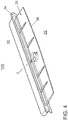
- FIG. 5 shows a plan view of a sectional illustration of a lighting device 50 of a motor vehicle 100 according to the invention in a further exemplary embodiment.
- the lighting device 50 comprises a cooling body 14, which is designed to accommodate a plurality of lighting means 40 and the light guide 35 and to cool the lighting means 40, of which in Figure 5 only one is shown.
- the light guide 35 has an angled shape.
- the light guide 35 also has a first light guide area 37 and a second light guide area 38, the first light guide area 37 facing the lighting means 40 and thus the coupling surface 34, while the second light guide area 38 faces a body part 90 and the coupling out surface 36 of the light guide 35 for coupling out the Light which is radiated into the light guide 35 by the lighting means 40 and guided through the light guide 35, faces.
- the first light guide area 37 is arranged at a predetermined angle ⁇ to the second light guide area 38. In the exemplary embodiment shown here, this angle ⁇ is 90 °, but it can also have a value between 0 ° and 90 °.
- the light guide 35 has a mirror 39 in the area of its curvature, which is designed as a total reflection mirror and is suitable for the light 99 which is introduced into the light guide 35 by the illuminants 40 at the coupling surface 34 becomes, from the first light guide area 37 into the second light guide area 38 and thus to the decoupling surface 36 or to reflect.
- the light guide 35 has a fork 41 which is “Y-shaped” in cross section and which is formed out of the light guide 35.
- a purely exemplary elongated housing 42 with a cup-shaped cross section into which the coupling surface 34 of the light guide 35 protrudes and in which the cooling body 14 and the lighting means 40 are arranged is connected to this fork 41.
- the light guide 35 itself is not arranged in a housing in this further exemplary embodiment.
- FIG. 6 shows a plan view of a sectional illustration of a lighting device 50 in a further embodiment.
- the lighting device 50 comprises a cooling body 14 which is designed to accommodate a multiplicity of lighting means 40 and the light guide 35 and to cool the lighting means 40.
- the light guide 35 is designed to guide the light 99, which is fed into the coupling-in surface 34 of the light-guide 35 by the illuminant 40, to a coupling-out surface 36, which is located in the area of a body part 90.
- the light guide 35 is curved.
- the light is coupled in via a lighting means 40 arranged in a housing 42 as described above and located on a cooling body 14.
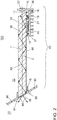
- FIGs 7a and 7b are two different side views of the in Figure 5 Another embodiment of a lighting device 50 of a motor vehicle 100 according to the invention shown in cross section is shown.
- a longitudinal side of the lighting device 50 is shown
- Figure 7b a broad side of the lighting device 50 is shown.
- the housing 42 already described is shown closed, so that the cooling body 14 arranged therein, together with the lighting means 40 arranged thereon and the coupling surface 34 of the light guide 35 is covered.
- the light guide 35 has a first and a second light guide area 37 and 38, which are angled to one another at an angle ⁇ .
- the first and second light guide regions 37 and 38 are connected to one another via an inclined section 44 of the light guide 35.
- the coupling-out surface 36 is formed from a plurality of compartments, in this further embodiment, purely by way of example, from five compartments, which are arranged in a step-like manner with respect to one another and are capable of coupling out light.
- the light guide 35 has a plurality of decoupling structures on its decoupling side 36, each of which protrudes in the form of a disk from the decoupling side 36 and, viewed together in cross section, has a stepped profile.
- lighting devices 50 of motor vehicles 100 according to the invention can also be implemented which have a multi-part housing 42.
- installation space can be kept free between the parts of the housing 42 for further components of the motor vehicle 100, over which the light guide 35 protrudes.
- Such components can be, for example, a camera, for example a reversing camera or a rearview camera.
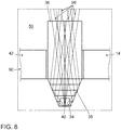
- FIG 8 the coupling of light into the light guide 35 of a further exemplary embodiment of a lighting device 50 of a motor vehicle 100 according to the invention is shown.
- a light guide 35 of a further exemplary embodiment of a lighting device 50 is shown in cross section, which has a coupling surface 34 at its lower end, into which light is coupled by means of a lighting means 40.
- the light guide 35 shown is its coupling-out side 36, from which the light 99 coupled into the coupling-in side 34 is decoupled.
- a part of a heat sink 14 is shown which has a holding rail (not shown) into which a rib (not shown) formed on the light guide 35 is inserted for the purpose of connecting the light guide 35 and the heat sink 14.
- Links in Figure 8 a part of a housing 42 is shown, which in turn is connected to a body part 90.
- the light guide 35 is connected to the housing in the same way as it is connected to the heat sink 14 via a rib molded onto the light guide 35.
- the ribs are attached very close to the coupling surface 34 of the light guide 35, only very few of the light beams are reflected on the wall of the light guide 35 via total reflection in this area. Thus, the optical loss is at most very low and the optical efficiency of the light guide 35 or the lighting device 50 is very high.
Description
Die vorliegende Erfindung betrifft ein Kraftfahrzeug, welches ein Karosserieteil umfasst, welches einen inneren Bereich von einem äußeren Bereich des Kraftfahrzeugs zumindest teilweise räumlich trennt und eine Öffnung aufweist sowie eine Leuchtvorrichtung umfasst, welche mindestens ein Leuchtmittel, einen Lichtleiter mit einer Einkoppelfläche und einer Auskoppelfläche aufweist, wobei die Einkoppelfläche vor dem mindestens einen Leuchtmittel angeordnet ist, so dass von dem Leuchtmittel emittiertes Licht in die Einkoppelfläche eingestrahlt wird.The present invention relates to a motor vehicle which comprises a body part which at least partially spatially separates an inner area from an outer area of the motor vehicle and has an opening and comprises a lighting device which has at least one light source, a light guide with a coupling-in surface and a coupling-out surface, wherein the coupling surface is arranged in front of the at least one illuminant, so that light emitted by the illuminant is radiated into the coupling surface.
Aus der
Ferner sind aus der
Die
Die
Die
Die Bedeutung von Licht im Straßenverkehr als auch von Ambientelicht in und an einem Kraftfahrzeug hat in den letzten Jahren stetig zugenommen. Dies ist unter anderem auch auf die Zunahme der Bedeutung von zum Beispiel den Fahrzeug-Scheinwerfern als herausstechende Designmerkmale eines Kraftfahrzeugs insgesamt zurückführbar. Allerdings sind die derzeit auf dem Markt verfügbaren Beleuchtungssysteme des Standes der Technik sehr komplex im Aufbau beziehungsweise sehr bauteilaufwändig. Es ist daher Aufgabe der vorliegenden Erfindung, ein Kraftfahrzeug mit einer Leuchtvorrichtung bereitzustellen, welche einen einfachen Aufbau aufweist, kostengünstig ist sowie unter gegenüber dem Stand der Technik verringertem Bauteilbedarf herstellbar und innerhalb des Kraftfahrzeuges platzsparend verbaubar ist.The importance of light in road traffic and of ambient light in and on a motor vehicle has increased steadily in recent years. Among other things, this can also be traced back to the overall increase in the importance of vehicle headlights, for example, as outstanding design features of a motor vehicle. However, the state-of-the-art lighting systems currently available on the market are very complex in construction or very complex in terms of components. It is therefore the object of the present invention to provide a motor vehicle with a lighting device which has a simple structure, is inexpensive and can be manufactured with fewer components compared to the prior art and can be installed in a space-saving manner within the motor vehicle.
Die erfindungsgemäße Aufgabe wird mit einem Kraftfahrzeug gemäß dem Hauptanspruch gelöst. Vorteilhafte Ausgestaltungen sind in den Unteransprüchen beschrieben.The object of the invention is achieved with a motor vehicle according to the main claim. Advantageous embodiments are described in the subclaims.
Erfindungsgemäß wird ein Kraftfahrzeug bereitgestellt, welches ein Karosserieteil umfasst, welches einen inneren Bereich von einem äußeren Bereich des Kraftfahrzeugs zumindest teilweise räumlich trennt und eine Öffnung aufweist. Ferner umfasst das Kraftfahrzeug eine Leuchtvorrichtung, welche mindestens ein Leuchtmittel sowie einen Lichtleiter mit einer Einkoppelfläche und einer Auskoppelfläche umfasst, wobei die Einkoppelfläche vor dem mindestens einen Leuchtmittel angeordnet ist, so dass von dem Leuchtmittel emittiertes Licht in die Einkoppelfläche eingestrahlt wird. Erfindungsgemäß ist die Leuchtvorrichtung im inneren Bereich des Kraftfahrzeugs angeordnet, und der Lichtleiter ragt mit seiner Auskoppelfläche von innen in die Öffnung des Karosserieteils hinein.According to the invention, a motor vehicle is provided which comprises a body part which at least partially spatially separates an inner area from an outer area of the motor vehicle and has an opening. Furthermore, the motor vehicle comprises a lighting device which comprises at least one light source and a light guide with a coupling-in surface and a coupling-out surface, the coupling-in surface being arranged in front of the at least one lighting device so that light emitted by the lighting device is radiated into the coupling-in surface. According to the invention, the lighting device is arranged in the inner region of the motor vehicle, and the light guide protrudes with its coupling-out surface from the inside into the opening of the body part.
Der Lichtleiter ist totalreflektierend ausgeführt. Solche Lichtleiter eignen sich besonders gut für die Verwendung innerhalb der Leuchtvorrichtungen erfindungsgemäßer Kraftfahrzeuge, da nur ein geringer Teil des in die Einkoppelfläche des Lichtleiters eingekoppelten Lichtes an der nicht die Auskoppelfläche des Lichtleiters ausmachenden Oberfläche des Lichtleiters verloren geht.The light guide is designed to be totally reflective. Such light guides are particularly suitable for use within the lighting devices of motor vehicles according to the invention, since only a small part of the light coupled into the coupling surface of the light guide is lost on the surface of the light guide that does not make up the output surface of the light guide.
Die Einkoppelfläche ist durch einen Kollimator, also durch eine Kollimatorlinse gebildet. Ferner bevorzugt ist die Einkoppelfläche durch eine Fresnel Optik, also durch eine Fresnel-Linse gebildet. Des Weiteren bevorzugt umfasst die Einkoppelfläche einen Kollimator beziehungsweise eine Fresnel Optik, also eine Kollimatorlinse beziehungsweise eine Fresnel-Linse. In anderen Ausführungsformen von Leuchtvorrichtungen erfindungsgemäßer Kraftfahrzeuge erfolgt die Einkopplung von Licht in den Lichtleiter mittels eines weiteren Lichtleitelementes, dessen Auskoppelseite parallel zu der Einkoppelfläche des Lichtleiters ausgebildet ist.The coupling surface is formed by a collimator, that is to say by a collimator lens. Furthermore, the coupling surface is preferably formed by a Fresnel optic, that is to say by a Fresnel lens. Furthermore, the coupling surface preferably comprises a collimator or Fresnel optics, that is to say a collimator lens or a Fresnel lens. In other embodiments of lighting devices of motor vehicles according to the invention, light is coupled into the light guide by means of a further light guide element, the coupling-out side of which is formed parallel to the coupling surface of the light guide.
Erfindungsgemäß ist ein lichtstreuender Kunststoff in die Auskoppelfläche des Lichtleiters eingebracht. Dadurch kann mittels der Leuchtvorrichtung beispielsweise ein diffuses Lichtbild erzeugt werden, ohne dass der Verbau spezieller Optiken notwendig ist. Ferner bevorzugt handelt es sich bei dem lichtstreuenden Kunststoff um ein Polymethylmethacrylat. Polymethylmethacrylat weist eine hervorragende Chemikalienbeständigkeit sowie sehr gute mechanische Eigenschaften auf. Ferner bevorzugt handelt es sich bei dem lichtstreuenden Kunststoff um einen diffusen Kunststoff. Bevorzugt handelt es sich bei dem Kunststoff um ein Polycarbonat. Des Weiteren bevorzugt ist der Kunststoff transparent und/oder ist der Kunststoff mit Streupartikeln versetzt beziehungsweise Streupartikel aufweisend gespritzt.According to the invention, a light-scattering plastic is introduced into the coupling-out surface of the light guide. In this way, for example, a diffuse light image can be generated by means of the lighting device without the need to install special optics. Furthermore, the light-scattering plastic is preferably a polymethyl methacrylate. Polymethyl methacrylate has excellent chemical resistance and very good mechanical properties. Furthermore, the light-scattering plastic is preferably a diffuse plastic. The plastic is preferably a polycarbonate. Furthermore, the plastic is preferably transparent and / or is Plastic mixed with scattering particles or sprayed with scattering particles.
Ferner schließt die Auskoppelfläche des Lichtleiters vorzugsweise flächig mit den die Ränder der Öffnung bildenden Abschnitten des Karosserieteils ab, so dass das Karosserieteil sowie der Lichtleiter der Leuchtvorrichtung im fertig zusammengebauten Zustand des Kraftfahrzeugs von außen betrachtet eine durchgehende Außenkontur des Kraftfahrzeuges bilden.Furthermore, the decoupling surface of the light guide preferably closes flat with the sections of the body part that form the edges of the opening, so that the body part and the light guide of the lighting device form a continuous outer contour of the vehicle when viewed from the outside in the fully assembled state of the motor vehicle.
Bevorzugt sind die die Ränder der Öffnung bildenden Abschnitte des Karosserieteils in Richtung des inneren Bereiches des Kraftfahrzeugs gewölbt und verlaufen im zusammengebauten Zustand des Kraftfahrzeugs zumindest in einem Teilbereich dieses Abschnittes parallel zu dem Lichtleiter.The sections of the body part forming the edges of the opening are preferably curved in the direction of the inner region of the motor vehicle and, in the assembled state of the motor vehicle, run parallel to the light guide at least in a partial region of this section.
Der Vorteil eines derartigen Kraftfahrzeugs ist, dass bei der Realisierung von dessen erfindungsgemäßen Leuchtvorrichtung beziehungsweise Leuchtvorrichtungen auf eine Außenlichtscheibe und/oder gar auf ein Gehäuse verzichtet werden kann. Ferner sind die erfindungsgemäßen Leuchtvorrichtungen derartiger Kraftfahrzeuge kostengünstig und weisen einen sehr einfachen Aufbau auf. Da das erfindungsgemäße Kraftfahrzeug keine Außenlichtscheibe aufweist, ist eine Betauung der sichtbaren Komponenten der Leuchtvorrichtung, insbesondere der Auskoppelfläche des Lichtleitelementes der Leuchtvorrichtung, für einen äußeren Betrachter nicht sichtbar. Ferner weist die Leuchtvorrichtung erfindungsgemäßer Kraftfahrzeuge eine sehr hohe optische Effizienz auf.The advantage of such a motor vehicle is that, in the implementation of its lighting device or lighting devices according to the invention, an outside lens and / or even a housing can be dispensed with. Furthermore, the lighting devices according to the invention for such motor vehicles are inexpensive and have a very simple structure. Since the motor vehicle according to the invention does not have an outside lens, condensation on the visible components of the lighting device, in particular the coupling-out surface of the light guide element of the lighting device, is not visible to an external observer. Furthermore, the lighting device of motor vehicles according to the invention has a very high optical efficiency.
Bevorzugt umfasst die Leuchtvorrichtung ferner einen Kühlkörper, welcher dazu ausgebildet ist, das mindestens eine Leuchtmittel sowie den Lichtleiter aufzunehmen und das Leuchtmittel zu kühlen. Die Aufnahme von Leuchtmitteln und Lichtleitern durch den Kühlkörper ist ausschlaggebend für den kompakten und platzsparenden Aufbau der Leuchtvorrichtung, da durch selbige auf zusätzlich vorzusehende Mittel zur Fixierung der Komponenten der Leuchtvorrichtung verzichtet werden kann.The lighting device preferably further comprises a heat sink which is designed to accommodate the at least one lighting means and the light guide and to cool the lighting means. The inclusion of illuminants and light guides through the heat sink is crucial for the compact and space-saving design of the lighting device, since this means that additional means for fixing the components of the lighting device can be dispensed with.
In einer bevorzugten Ausführungsform sind sowohl das mindestens eine Leuchtmittel als auch der Lichtleiter fest mit dem Kühlkörper verbunden und der Kühlkörper ist im inneren Bereich fest mit dem Kraftfahrzeug verbunden. In einer derartigen Ausführungsform bildet der Kühlkörper also nicht nur eine wesentliche beziehungsweise die tragende Komponente im Aufbau der Leuchtvorrichtung, sondern dient gleichzeitig der Fixierung der Leuchtvorrichtung innerhalb des Kraftfahrzeugs. In einem derart ausgeführten Kraftfahrzeug ist der von der Realisierung beziehungsweise von der Anordnung der Leuchtvorrichtung innerhalb des Kraftfahrzeugs beanspruchte Bauraum abermals reduziert. Des Weiteren bevorzugt ist das Leuchtmittel und/oder der Lichtleiter über einen Formschluss oder einen Kraftschluss mit dem Kühlkörper verbunden. Des Weiteren bevorzugt ist das Leuchtmittel und/oder der Lichtleiter über eine stoffschlüssige Verbindung mit dem Kühlkörper verbunden. Besonders bevorzugt weist der Lichtleiter mindestens eine Befestigungsnase auf, welche formschlüssig mit mindestens einer auf dem Kühlköper angeordneten oder aus diesem ausgeformten Halteschiene verbunden ist. Ganz besonders bevorzugt ist der Lichtleiter über die mindestens eine Befestigungsnase mit der mindestens einen auf dem Kühlköper angeordneten oder aus diesem ausgeformten Halteschiene und somit mit dem Kühlkörper verklebt.In a preferred embodiment, both the at least one illuminant and the light guide are permanently connected to the cooling body and the cooling body is permanently connected to the motor vehicle in the inner area. In such an embodiment, the heat sink not only forms an essential or the supporting component in the structure of the lighting device, but also serves to fix the lighting device inside the motor vehicle. In a motor vehicle designed in this way the installation space required by the implementation or by the arrangement of the lighting device within the motor vehicle is again reduced. Furthermore, the lighting means and / or the light guide is preferably connected to the heat sink via a form fit or a force fit. Furthermore, the lighting means and / or the light guide is preferably connected to the heat sink via an integral connection. The light guide particularly preferably has at least one fastening nose which is positively connected to at least one holding rail arranged on the cooling body or formed from it. Very particularly preferably, the light guide is glued to the at least one holding rail arranged on the cooling body or formed therefrom via the at least one fastening nose and thus glued to the cooling body.
Besonders bevorzugt weist der Lichtleiter an seiner dem Kühlkörper zugewandten Seite direkt vor und/oder direkt hinter seiner Einkoppelfläche angeformte Rippen auf, mittels welchen der Lichtleiter auf beziehungsweise an einem Kühlkörper und/oder an einem im Kraftfahrzeug befindlichen Gehäuse fixierbar ist. Ferner bevorzugt weist der Lichtleiter unmittelbar vor und/oder unmittelbar hinter seiner Einkoppelfläche beziehungsweise benachbart zu seiner Einkoppelfläche angeformte Rippen oder andere aus dem Lichtleiter ausgeformte Befestigungsstrukturen auf, mittels welchen der Lichtleiter auf einem Kühlkörper und/oder an einem im Kraftfahrzeug befindlichen Gehäuse fixierbar ist. Bevorzugt sind die angeformten Rippen in jeweils eine am Gehäuse beziehungsweise im Kühlkörper befindliche Aufnahmeschiene beziehungsweise Aufnahmestruktur einführbar. Dadurch, dass die angeformten Rippen beziehungsweise die aus dem Lichtleiter ausgeformten Befestigungsstrukturen unmittelbar in der Nähe der Einkoppelfläche des Lichtleiters ausgebildet beziehungsweise vorgesehen sind, ist der sich durch die Rippen ergebende optische Verlust minimal beziehungsweise stark reduziert. Da nur wenige der in den Lichtleiter eingespeisten Lichtstrahlen im Bereich der angeformten Rippen beziehungsweise im Bereich der aus dem Lichtleiter ausgeformten Befestigungsstrukturen über Totalreflektion an der Wand des Lichtleiters reflektiert werden, bleibt die optische Effizienz des Lichtleiters weitgehend unbeeinträchtigt.Particularly preferably, the light guide has molded ribs on its side facing the heat sink directly in front of and / or directly behind its coupling surface, by means of which the light guide can be fixed on or on a heat sink and / or on a housing located in the motor vehicle. Furthermore, the light guide preferably has ribs or other fastening structures formed from the light guide directly in front of and / or immediately behind its coupling surface or adjacent to its coupling surface, by means of which the light guide can be fixed on a heat sink and / or on a housing located in the motor vehicle. Preferably, the molded-on ribs can each be inserted into a receiving rail or receiving structure located on the housing or in the heat sink. Because the molded-on ribs or the fastening structures formed from the light guide are formed or provided directly in the vicinity of the coupling-in surface of the light guide, the optical loss resulting from the ribs is minimally or greatly reduced. Since only a few of the light beams fed into the light guide are reflected in the area of the molded ribs or in the area of the fastening structures formed from the light guide via total reflection on the wall of the light guide, the optical efficiency of the light guide remains largely unaffected.
Ferner bevorzugt weist das Karosserieteil mindestens eine Komponente auf. Des Weiteren bevorzugt umfasst das Karosserieteil mindestens zwei Teil-Karosserieteile, welche im zusammengebauten Zustand des Kraftfahrzeugs gemeinsam die Öffnung bilden.The body part also preferably has at least one component. Furthermore, the body part preferably comprises at least two part body parts which together form the opening in the assembled state of the motor vehicle.
Bevorzugt liegt die Auskoppelfläche in einer Ebene mit den die Ränder der Öffnung bildenden Abschnitten des Karosserieteils. In derartig ausgeführten Kraftfahrzeugen ist die Leuchtvorrichtung in die Karosserie des Kraftfahrzeugs integriert. Somit steht innerhalb des Kraftfahrzeugs gegenüber dem Stand der Technik ein vergrößerter Bauraum zur Verfügung. Bevorzugt ist die Auskoppelfläche des Lichtleiters flach ausgeführt. Ferner bevorzugt weist die Auskoppelfläche des Lichteiters eine Höhe auf, welche einem Bruchteil der Länge des Lichtleiters entspricht. Besonders bevorzugt bewegt sich die Höhe des Lichtleiters in einem Bereich zwischen 0,5 cm und 3,5 cm. Besonders bevorzugt füllt die Auskoppelfläche eine im Karosserieteil des Kraftfahrzeugs gegebene Öffnung auf. Bevorzugt ist die Öffnung als Spalt oder als Fuge ausgebildet.The decoupling surface preferably lies in a plane with the sections of the body part that form the edges of the opening. In motor vehicles designed in this way, the Lighting device integrated into the body of the motor vehicle. Compared to the prior art, there is thus an enlarged installation space available within the motor vehicle. The coupling-out surface of the light guide is preferably designed to be flat. Furthermore, the coupling-out surface of the light guide preferably has a height which corresponds to a fraction of the length of the light guide. The height of the light guide is particularly preferably in a range between 0.5 cm and 3.5 cm. Particularly preferably, the coupling-out area fills an opening provided in the body part of the motor vehicle. The opening is preferably designed as a gap or as a joint.
In einer bevorzugten Ausführungsform ist der Lichtleiter als zwei-Komponenten-Kunststoff ausgeführt. Derartige zwei-Komponenten-Kunststoffe sind besonders günstig und einfach herstellbar. Beispielsweise können die beiden Komponenten in einem zwei-Komponenten-Spritzgussverfahren gespritzt werden.In a preferred embodiment, the light guide is designed as a two-component plastic. Such two-component plastics are particularly cheap and easy to manufacture. For example, the two components can be injected using a two-component injection molding process.
In einer bevorzugten Weiterentwicklung dieser Ausführungsform weist die erste Komponente des zwei-Komponenten-Kunststoffs einen ersten Brechungsindex auf, welcher von dem zweiten Brechungsindex der zweiten Komponente verschieden ist. Durch die Wahl der für die Realisierung des Lichtleiters zu verwendenden Materialien können über die zueinander verschiedenen Brechungsindizes der Materialien die optischen Eigenschaften des Lichtleiters gezielt und präzise eingestellt werden.In a preferred further development of this embodiment, the first component of the two-component plastic has a first refractive index which is different from the second refractive index of the second component. By choosing the materials to be used for the realization of the light guide, the optical properties of the light guide can be set in a targeted and precise manner via the different refractive indices of the materials.
In einer ferner bevorzugten Weiterentwicklung dieser Ausführungsform erhält die Leuchtvorrichtung durch die Wahl des ersten und zweiten Brechungsindex eine vorbestimmte Abstrahlcharakteristik. Bei Kraftfahrzeugen mit derart ausgeführten Leuchtvorrichtungen können selbige zur Erzeugung einer charakteristischen, wiedererkennbaren Abstrahlcharakteristik verwandt werden, über welche das Kraftfahrzeug eindeutig identifizierbar ist.In a further preferred further development of this embodiment, the lighting device is given a predetermined emission characteristic through the selection of the first and second refractive index. In motor vehicles with lighting devices designed in this way, the same can be used to generate a characteristic, recognizable emission characteristic by means of which the motor vehicle can be clearly identified.
Bevorzugt ist das Karosserieteil als Stoßfänger ausgeführt. Ferner bevorzugt ist das Karosserieteil als Heckklappe ausgeführt. Bevorzugt ist der Leuchtvorrichtung eine Tagfahrlichtfunktion, eine Standlichtfunktion, eine Blinklichtfunktion oder eine beliebige andere Lichtfunktion zugeordnet. Ferner bevorzugt fungiert die Leuchtvorrichtung als Nebelschlusslicht, als Rückfahrlicht, als Blinklicht, als Tagfahrlicht, als eine Vorfeldleuchte, als eine Kennzeichenleuchte oder als Sidemarker. Des Weiteren bevorzugt ist die Leuchtvorrichtung in einer Fuge angeordnet, welche zwischen zwei Karosserieteilen gebildet ist.The body part is preferably designed as a bumper. The body part is also preferably designed as a tailgate. The lighting device is preferably assigned a daytime running light function, a parking light function, a flashing light function or any other light function. Furthermore, the lighting device preferably functions as a rear fog light, a reversing light, a flashing light, a daytime running light, an apron light, a license plate light or a side marker. Furthermore, the lighting device is preferably arranged in a joint which is formed between two body parts.
Bevorzugt ist die Leuchtvorrichtung als Bremsleuchte ausgeführt und/oder im Heck des Kraftfahrzeuges angeordnet. Als Bremsleuchte, beispielsweise als hoch- oder tiefgesetzte Bremsleuchte trägt die Leuchtvorrichtung eines erfindungsgemäßen Kraftfahrzeugs im besonderen Maße zu einer besseren Wahrnehmbarkeit des Kraftfahrzeugs im Straßenverkehr bei.The lighting device is preferably designed as a brake light and / or arranged in the rear of the motor vehicle. As a brake light, for example as a raised or lowered brake light, the lighting device of a motor vehicle according to the invention makes a particular contribution to better perceptibility of the motor vehicle in traffic.
Ausführungsbeispiele der Erfindung werden anhand der Zeichnungen und der nachfolgenden Beschreibung näher erläutert. Es zeigen:
Figur 1- ein erstes Ausführungsbeispiel eines erfindungsgemäßen Kraftfahrzeugs,
Figur 2- eine seitliche Ansicht des ersten Ausführungsbeispiels der Leuchtvorrichtung des erfindungsgemäßen Kraftfahrzeugs,
Figur 3- eine Draufsicht auf die geschnitten dargestellte Leuchtvorrichtung des ersten Ausführungsbeispiels des erfindungsgemäßen Kraftfahrzeugs, und
- Figur 4
- ein weiteres Ausführungsbeispiel einer Leuchtvorrichtung eines erfindungsgemäßen Kraftfahrzeuges.
- Figur 5
- eine Draufsicht auf eine geschnittene Darstellung einer Leuchtvorrichtung eines weiteren Ausführungsbeispiels des erfindungsgemäßen Kraftfahrzeugs,
- Figur 6
- eine Draufsicht auf eine geschnittene Darstellung einer Leuchtvorrichtung eines weiteren Ausführungsbeispiels des erfindungsgemäßen Kraftfahrzeugs,
- Figur 7a - 7b
- zwei verschiedene seitliche Ansichten eines weiteren Ausführungsbeispiels einer Leuchtvorrichtung eines erfindungsgemäßen Kraftfahrzeugs, und
- Figur 8
- die Lichteinkopplung in den Lichtleiter eines weiteren Ausführungsbeispiels einer Leuchtvorrichtung eines erfindungsgemäßen Kraftfahrzeugs.
- Figure 1
- a first embodiment of a motor vehicle according to the invention,
- Figure 2
- a side view of the first embodiment of the lighting device of the motor vehicle according to the invention,
- Figure 3
- a plan view of the lighting device shown in section of the first embodiment of the motor vehicle according to the invention, and
- Figure 4
- another embodiment of a lighting device of a motor vehicle according to the invention.
- Figure 5
- a plan view of a sectional view of a lighting device of a further embodiment of the motor vehicle according to the invention,
- Figure 6
- a plan view of a sectional view of a lighting device of a further embodiment of the motor vehicle according to the invention,
- Figures 7a-7b
- two different side views of a further embodiment of a lighting device of a motor vehicle according to the invention, and
- Figure 8
- the coupling of light into the light guide of a further embodiment of a lighting device of a motor vehicle according to the invention.
In der
Es können auch erfindungsgemäße Kraftfahrzeuge 100 ausgeführt sein, bei welchen die Leuchtvorrichtung 50 in die Öffnung 15 eines anderen Karosserieteils 90 hineinragt, bei welchen das Karosserieteil 90 also nicht als Stoßfänger ausgeführt ist. Beispielsweise kann es sich bei dem Karosserieteil 90 des Kraftfahrzeugs 100 auch um die Heckklappe, oder aber auch um ein beliebiges anderes Karosserieteil 90 des Kraftfahrzeugs 100 handeln. Auch kann die erfindungsgemäße Leuchtvorrichtung 50 an einer anderen Position am Kraftfahrzeug 100 verbaut sein.
Die
In dem ersten Ausführungsbeispiel umfasst die Leuchtvorrichtung 50 einen Kühlkörper 14, welcher dazu ausgebildet ist, die Vielzahl an Leuchtmitteln 40, von denen in
Sind der Lichtleiter 35 und das Leuchtmittel 40 von dem Kühlkörper 14 aufgenommen beziehungsweise mit dem Kühlkörper 14 verbunden, so strahlen die Leuchtmittel 40 im Betrieb Licht in die Einkoppelfläche 34 des Lichtleiters 35 ein. In diesem ersten Ausführungsbeispiel weist der Lichtleiter 35 im an seiner Einkoppelfläche 34 beziehungsweise in dem Bereich der Lichteinstrahlung durch die Leuchtmittel 40 eine Aussparung auf, welche sich als Rille durch die Unterseite des Lichtleiters 35 über dessen gesamte Breite erstreckt. An der Hinterseite 16 des Kühlkörpers 14 weist selbiger in diesem ersten Ausführungsbeispiel zwei optionale Klemmen 22 auf, über welche der Kühlkörper 14 samt Leuchtvorrichtung 50 im Kraftfahrzeug 100 mittels einer Klemmverbindung befestigt ist (nicht dargestellt). In diesem ersten Ausführungsbeispiel ist die Einkoppelfläche 34 wie bereits erwähnt durch eine Aussparung an der Unterseite des Lichtleiters 35 gebildet. Es können allerdings auch andere Ausführungsbeispiele von Leuchtvorrichtungen 50 erfindungsgemäßer Kraftfahrzeuge 100 realisiert werden, bei welchen die Einkoppelfläche 34 durch einen Kollimator, beziehungsweise durch eine Kollimationslinse oder durch eine Fresnel Optik, also zum Beispiel durch eine Fresnel-Linse oder durch ein weiteres Lichtleitelement mit einer zu der Einkoppelfläche 34 des Lichtleiters 35 parallelen Auskoppelseite oder aber auch ganz anders ausgebildet sein.If the
In diesem ersten Ausführungsbeispiel ist der Lichtleiter 35 rein beispielhaft als zwei-Komponenten-Kunststoff ausgeführt. Dabei weist die erste Komponente 1 des zwei-Komponenten-Kunststoffs einen ersten Brechungsindex auf und die zweite Komponente 2 des zwei-Komponenten-Kunststoffs einen zweiten Brechungsindex auf. Ferner handelt es sich bei dem Lichtleiter 35 in diesem ersten Ausführungsbeispiel um einen totalreflektierenden Lichtleiter 35. Durch die Wahl des ersten und zweiten Brechungsindex erhält die Leuchtvorrichtung 50 eine vorbestimmte Abstrahlcharakteristik, da über die Brechungsindizes der ersten und zweiten Komponente 1, 2 die Lichtdurchmischung innerhalb des Lichtleiters 35 eingestellt werden kann. Die Auskoppelfläche 36 des Lichtleiters 35 ist in diesem ersten Ausführungsbeispiel rein beispielhaft glatt und weist keine Optik auf. Es können allerdings auch erfindungsgemäße Kraftfahrzeuge 100 mit Leuchtvorrichtungen 50 ausgeführt werden, bei welchen auf den Auskoppelflächen 36 Optiken vorgesehen sind. Bei diesen Optiken kann es sich rein beispielhaft um Kissenoptiken oder Rillenoptiken oder aber auch um andere Optiken beziehungsweise Typen von Optiken handeln.In this first exemplary embodiment, the
Ferner ist in diesem ersten Ausführungsbeispiel ein lichtstreuender Kunststoff in die Auskoppelfläche 36 des Lichtleiters 35 eingebracht, durch welchen dass aus der Auskoppelfläche 36 des Lichtleiters 35 austretende Licht 99 gestreut wird. Die Auskoppelfläche 36 des in die Öffnung 15 des Karosserieteils 90 hineinragenden Lichtleiters 35 schließt in diesem ersten Ausführungsbeispiel flächig mit den die Ränder der Öffnung 15 bildenden Abschnitten 91, 92 des Karosserieteils 90 ab. Mit anderen Worten ausgedrückt liegt die Auskoppelfläche 36 in einer Ebene mit den die Ränder der Öffnung 15 bildenden Abschnitten 91, 92 des Karosserieteils 90. Somit bilden das Karosserieteil 90 und die Auskoppelfläche 36 des Lichtleiters 35 eine, von dem äußeren Bereich 20 aus betrachtet, durchgehende Außenkontur. In diesem ersten Ausführungsbeispiel ist die Auskoppelfläche 36 des Lichtleiters 35 sehr flach ausgeführt und füllt die in diesem ersten Ausführungsbeispiel als Spalt beziehungsweise als Fuge ausgebildete Öffnung 15 des Karosserieteils 90 aus. In diesem ersten Ausführungsbeispiel weist die Auskoppelfläche 36 des Lichtleiters 35 eine Höhe von rein beispielhaft ca. 0,5 cm auf. Es können auch erfindungsgemäße Kraftfahrzeuge 100 mit erfindungsgemäßen Leuchtvorrichtungen 50 ausgeführt sein, bei welchen die Öffnung 15 durch zwei oder gar mehr als zwei Karosserieteile 90 beziehungsweise zwei Teil-Karosserieteile gebildet ist beziehungsweise bereitgestellt wird. In diesem ersten Ausführungsbeispiel sind die Ränder der Öffnung 15 in den inneren Bereich 10 hineingebogen und rein beispielhaft um die Öffnung 15 und damit um die Auskoppelfläche 36 beziehungsweise um das auskoppelseitige Ende des Lichtleiters 35 umlaufend ausgeführt. Die nach innen, also in den inneren Bereich 10 des Karosserieteils 90 gebogenen Abschnitte des Karosserieteils 90, welche sich an die die Ränder der Öffnung 15 bildenden Abschnitte 91, 92 des Karosserieteils 90 anschließen, verlaufen in diesem ersten Ausführungsbeispiel parallel zu dem als Platte ausgeführten Lichtleiter 35.Furthermore, in this first exemplary embodiment a light-scattering plastic is introduced into the coupling-
Die
In diesem ersten Ausführungsbeispiel des erfindungsgemäßen Kraftfahrzeugs 100 weist die Leuchtvorrichtung 50 rein beispielhaft ein Gehäuse (nicht dargestellt), aber keine Außenlichtscheibe auf. Es können allerdings auch erfindungsgemäße Kraftfahrzeuge 100 ausgeführt werden, in welchen die Leuchtvorrichtungen 50 kein Gehäuse und keine Außenlichtscheibe aufweisen.In this first exemplary embodiment of the
In
Im Gegensatz zu dem in
Der Lichtleiter 35 weist ferner einen ersten Lichtleiterbereich 37 und einen zweiten Lichtleiterbereich 38 auf, wobei der erste Lichtleiterbereich 37 den Leuchtmitteln 40 und somit der Einkoppelfläche 34 zugewandt ist, während der zweite Lichtleiterbereich 38 einem Karosserieteil 90 und der Auskoppelfläche 36 des Lichtleiters 35 zur Auskopplung des Lichtes, welches durch die Leuchtmittel 40 in den Lichtleiter 35 eingestrahlt und durch den Lichtleiter 35 geführt wird, zugewandt ist. Der erste Lichtleiterbereich 37 ist dabei in einem vorbestimmten Winkel α zum zweiten Lichtleiterbereich 38 angeordnet. Dieser Winkel α beträgt in dem hier gezeigten Ausführungsbeispiel 90°, er kann aber auch einen Wert zwischen 0° und 90° aufweisen. Zwischen dem ersten Lichtleiterbereich 37 und dem zweiten Lichtleiterbereich 38 weist der Lichtleiter 35 im Bereich seiner Krümmung einen Spiegel 39 auf, der als Totalreflektionsspiegel ausgeführt und dazu geeignet ist, das Licht 99, welches durch die Leuchtmittel 40 an der Einkoppelfläche 34 in den Lichtleiter 35 eingebracht wird, von dem ersten Lichtleiterbereich 37 in den zweiten Lichtleiterbereich 38 und somit zur Auskoppelfläche 36 zu führen beziehungsweise zu reflektieren. Der Lichtleiter 35 weist im Bereich seiner Einkoppelfläche 34 eine im Querschnitt "Y-förmige" Gabelung 41 auf, welche aus dem Lichtleiter 35 heraus geformt ist. Mit dieser Gabelung 41 verbunden ist in diesem Ausführungsbeispiel ein rein beispielhaft längliches, im Querschnitt topfförmiges Gehäuse 42, in welches die Einkoppelfläche 34 des Lichtleiters 35 hineinragt und in welchem der Kühlkörper 14 sowie die Leuchtmittel 40 angeordnet sind. Der Lichtleiter 35 selbst ist in diesem weiteren Ausführungsbeispiel nicht in einem Gehäuse angeordnet.The
In den
In
Da die Rippen sehr nahe an der Einkoppelfläche 34 des Lichtleiters 35 angebracht sind, werden in diesem Bereich nur sehr wenige der Lichtstrahlen über Totalreflektion an die Wand des Lichtleiters 35 reflektiert. Somit ist der optische Verlust allenfalls sehr gering und die optische Effizienz des Lichtleiters 35 beziehungsweise der Leuchtvorrichtung 50 sehr hoch.Since the ribs are attached very close to the
Claims (10)
- Motor vehicle (100), comprising- a chassis part (90) that at least partially spatially separates an inner region (10) from an outer region (20) of the motor vehicle (100) and has an opening (15),- a light-emitting apparatus (50), comprising- at least one light-emitting means (40),- a light guide (35) having an input coupling face (34) and an output coupling face (36), wherein the input coupling face (34) is arranged in front of the at least one light-emitting means (40) so that light (99) emitted by the light-emitting means (40) is radiated into the input coupling face (34), the light-emitting apparatus (50) is arranged in the inner region (10) of the motor vehicle (100), and the light guide (35) protrudes with its output coupling face (36) from the inside into the opening (15) of the chassis part (90), that the light guide (35) is designed for total internal reflection, and the input coupling face (34) is formed by a collimator or comprises the latter, characterized in that a light-scattering plastic is incorporated in the output coupling face (36) of the light guide (35).
- Motor vehicle (100) according to Claim 1, characterized in that the light-emitting apparatus (50) furthermore comprises a heat sink (14) embodied to accommodate the at least one light-emitting means (40) and the light guide (35) and to cool the light-emitting means (40).
- Motor vehicle (100) according to Claim 2, characterized in that both the at least one light-emitting means (40) and the light guide (35) are fixedly connected to the heat sink (14) and wherein the heat sink (14) is fixedly connected, in the inner region (10), to the motor vehicle (100).
- Motor vehicle (100) according to one of Claims 1 to 3, characterized in that the output coupling face (36) of the light guide (35) terminates flush with the portions (91, 92) of the chassis part (90) that form the peripheries of the opening (15).
- Motor vehicle (100) according to Claim 4, characterized in that the output coupling face (36) lies in one plane with the portions (91, 92) of the chassis part (90) that form the peripheries of the opening (15).
- Motor vehicle (100) according to one of Claims 1 to 5, characterized in that the light guide (35) is embodied as a two-component plastic.
- Motor vehicle (100) according to Claim 6, characterized in that the first component (1) of the two-component plastic has a first refractive index that differs from the second refractive index of the second component (2).
- Motor vehicle (100) according to Claim 7, characterized in that the light-emitting apparatus (50) acquires a predetermined radiation pattern due to the selection of the first and second refractive indices.
- Motor vehicle (100) according to one of Claims 1 to 8, characterized in that the chassis part (90) is designed as a bumper.
- Motor vehicle (100) according to one of Claims 1 to 9, characterized in that the light-emitting apparatus (50) is designed to be a brake light and/or is arranged at the rear of the motor vehicle (100).
Applications Claiming Priority (2)
| Application Number | Priority Date | Filing Date | Title |
|---|---|---|---|
| DE102013010489 | 2013-06-22 | ||
| DE102014206238.1A DE102014206238A1 (en) | 2013-06-22 | 2014-04-02 | Motor vehicle with a lighting device |
Publications (3)
| Publication Number | Publication Date |
|---|---|
| EP2816276A2 EP2816276A2 (en) | 2014-12-24 |
| EP2816276A3 EP2816276A3 (en) | 2015-11-25 |
| EP2816276B1 true EP2816276B1 (en) | 2021-02-17 |
Family
ID=50819581
Family Applications (1)
| Application Number | Title | Priority Date | Filing Date |
|---|---|---|---|
| EP14169773.0A Active EP2816276B1 (en) | 2013-06-22 | 2014-05-26 | Motor vehicle with a lighting device |
Country Status (2)
| Country | Link |
|---|---|
| EP (1) | EP2816276B1 (en) |
| DE (1) | DE102014206238A1 (en) |
Families Citing this family (16)
| Publication number | Priority date | Publication date | Assignee | Title |
|---|---|---|---|---|
| DE102015222505A1 (en) * | 2015-11-16 | 2017-05-18 | Bayerische Motoren Werke Aktiengesellschaft | Lighting device for a motor vehicle |
| DE102016206753A1 (en) | 2016-04-21 | 2017-10-26 | Osram Gmbh | LIGHTING DEVICE FOR A MOTOR VEHICLE AND MOTOR VEHICLE WITH THE LIGHTING DEVICE |
| ITUA20163800A1 (en) * | 2016-05-25 | 2017-11-25 | Automotive Lighting Italia Spa | AUTOMOTIVE LIGHTING APPLIANCE |
| ITUA20164809A1 (en) | 2016-06-30 | 2017-12-30 | Automotive Lighting Italia Spa | AUTOMOTIVE HEADLIGHT INCLUDING A PORTION OF LUMINOUS EMISSION WITH OPALESCENT EFFECT |
| FR3054641B1 (en) * | 2016-07-29 | 2022-06-24 | Valeo Iluminacion Sa | THIRD STOP LIGHT WITH REDUCED THICKNESS EXIT FACE |
| SI25296A (en) * | 2016-10-21 | 2018-04-30 | Hella Saturnus Slovenija d.o.o. | Motor vehicle lighting device |
| FR3062453B1 (en) * | 2017-01-27 | 2019-03-29 | Peugeot Citroen Automobiles Sa | LIGHT GUIDE LIGHTING DEVICE MOUNTED ON A CARRIER PART INCORPORATING A TRANSPARENT EXPANSION SCREEN |
| FR3063797B1 (en) * | 2017-03-07 | 2019-03-22 | Peugeot Citroen Automobiles Sa | LIGHTING DEVICE WITH SIMPLIFIED AND PRECISE POSITIONING OF LIGHT SOURCES AND LIGHT GUIDES |
| ES2693586B2 (en) | 2017-06-08 | 2020-06-16 | Seat Sa | Lighting device for a vehicle, and associated tailgate. |
| FR3071041A1 (en) * | 2017-09-12 | 2019-03-15 | Psa Automobiles Sa | VEHICLE OPTICAL BLOCK WITH LIGHT GUIDE (S) WITH PROTUBERANCE OF LIMITATION OF PASSAGE OF PHOTONS PARASITES |
| FR3078559B1 (en) * | 2018-03-01 | 2020-02-07 | Psa Automobiles Sa | VEHICLE LIGHTING DEVICE HAVING MASK WITH LIMIT OF EXTENSION OF PHOTOS FROM LIGHT GUIDES. |
| JP7024686B2 (en) * | 2018-10-31 | 2022-02-24 | オムロン株式会社 | Display device |
| FR3095259B1 (en) * | 2019-04-16 | 2021-03-19 | Psa Automobiles Sa | A planar light guide having a smooth finished light emitting surface and a motor vehicle light having such a guide. |
| EP4006410A1 (en) * | 2020-11-25 | 2022-06-01 | Marelli Automotive Lighting Italy S.p.A. | Automotive lighting and/or signaling device and assembly method thereof |
| DE102020134642A1 (en) | 2020-12-22 | 2022-06-23 | Rehau Automotive Se & Co. Kg | Trim part for a motor vehicle and method for producing a trim part |
| DE102022003969A1 (en) | 2022-10-25 | 2023-05-11 | Mercedes-Benz Group AG | Lighting arrangement for a vehicle |
Citations (1)
| Publication number | Priority date | Publication date | Assignee | Title |
|---|---|---|---|---|
| DE102005044447A1 (en) * | 2005-09-09 | 2007-03-22 | Schefenacker Vision Systems Germany Gmbh | Light especially for external mirror of a vehicle especially a motor vehicle that is preferably an LED has at least one cooling body in the heat-radiating region of the light source |
Family Cites Families (16)
| Publication number | Priority date | Publication date | Assignee | Title |
|---|---|---|---|---|
| DE2407451A1 (en) * | 1974-02-16 | 1975-08-21 | Volkswagenwerk Ag | Vehicle bumper with signal lights - has bundle of fibre optics connecting lights to window in flexible section of bumper |
| EP1167869A3 (en) * | 2000-07-01 | 2002-10-30 | Hella KG Hueck & Co. | Light guide |
| US6920269B1 (en) * | 2000-07-14 | 2005-07-19 | The Gates Corporation | Lens |
| DE10114460A1 (en) * | 2001-03-24 | 2002-09-26 | Volkswagen Ag | High level third brake light for motor vehicle is mounted behind motor vehicle rear windscreen, with light or at least light-emitting surface being arranged in black area of edge of screen |
| US6773154B2 (en) * | 2002-08-21 | 2004-08-10 | North American Lighting, Inc. | Automotive lighting device |
| DE10259623B4 (en) * | 2002-12-18 | 2011-09-22 | Hella Kgaa Hueck & Co. | vehicle light |
| DE20312518U1 (en) * | 2003-08-13 | 2003-12-24 | Fer Fahrzeugelektrik Gmbh | vehicle light |
| JP2007022325A (en) * | 2005-07-15 | 2007-02-01 | Fujikura Ltd | Lighting device of door for vehicle |
| JP4919041B2 (en) * | 2007-03-14 | 2012-04-18 | スタンレー電気株式会社 | Vehicle lighting |
| JP4946998B2 (en) * | 2008-03-31 | 2012-06-06 | 豊田合成株式会社 | Vehicle lighting device |
| JP4946997B2 (en) * | 2008-07-25 | 2012-06-06 | 豊田合成株式会社 | Vehicle lighting device |
| US7922374B2 (en) | 2008-12-22 | 2011-04-12 | GM Global Technology Operations LLC | Vehicle lamp assembly |
| DE102011078607A1 (en) | 2011-03-15 | 2012-09-20 | Automotive Lighting Reutlingen Gmbh | Lighting device for motor vehicle |
| DE102011016408A1 (en) * | 2011-04-08 | 2012-10-11 | GM Global Technology Operations LLC (n. d. Gesetzen des Staates Delaware) | Entry sill lighting for a motor vehicle |
| WO2013030040A1 (en) * | 2011-08-26 | 2013-03-07 | Johnson Controls Gmbh | Fixture having a light guide, in particular for the interior of a motor vehicle, and manufacturing method |
| DE102011117733A1 (en) * | 2011-11-07 | 2013-05-08 | Volkswagen Aktiengesellschaft | Vehicle e.g. police vehicle has belt-shaped signal lamp that is arranged at outer surface |
-
2014
- 2014-04-02 DE DE102014206238.1A patent/DE102014206238A1/en not_active Ceased
- 2014-05-26 EP EP14169773.0A patent/EP2816276B1/en active Active
Patent Citations (1)
| Publication number | Priority date | Publication date | Assignee | Title |
|---|---|---|---|---|
| DE102005044447A1 (en) * | 2005-09-09 | 2007-03-22 | Schefenacker Vision Systems Germany Gmbh | Light especially for external mirror of a vehicle especially a motor vehicle that is preferably an LED has at least one cooling body in the heat-radiating region of the light source |
Also Published As
| Publication number | Publication date |
|---|---|
| DE102014206238A1 (en) | 2014-12-24 |
| EP2816276A2 (en) | 2014-12-24 |
| EP2816276A3 (en) | 2015-11-25 |
Similar Documents
| Publication | Publication Date | Title |
|---|---|---|
| EP2816276B1 (en) | Motor vehicle with a lighting device | |
| DE19507234B4 (en) | Vehicle signal light with several LEDs | |
| DE102006035842B4 (en) | Vehicle lamp with a one-piece optical fiber aperture unit | |
| EP1327558A2 (en) | Vehicle lamp | |
| EP0780265A2 (en) | Vehicle rear light | |
| DE102013104174A1 (en) | Lighting device for vehicles | |
| DE102005013682A1 (en) | Exterior rearview mirror of vehicles, preferably motor vehicles | |
| WO2018149741A1 (en) | Lighting device for an interior trim part | |
| DE102010061210A1 (en) | Lamp for vehicle, has light guide with light exit side towards which portion of light passed from primary light source via light input side of light guide is totally reflected and deflected | |
| DE102017111805A1 (en) | Lighting device for motor vehicles | |
| EP2796322A1 (en) | Lighting device for a motor vehicle's external mirror and motor vehicle external mirror with such a lighting device | |
| DE102013009460A1 (en) | Lamp e.g. rear lid lamp, for use in rear region of motor car, has conductor comprising light coupling surface, light uncoupling surface and reflective surface, where light is uncoupled at uncoupling surface to create headlight function | |
| DE102014104756A1 (en) | Lighting device for vehicles | |
| EP1832902A1 (en) | Flat lamp device | |
| EP1913302B1 (en) | Light for motor vehicles | |
| DE10259236A1 (en) | Automobile interior light with different light sources for different lighting functions e.g. interior illumination and ambient lighting | |
| EP2108883B1 (en) | Signal light for motor vehicles | |
| DE102008048767A1 (en) | Lighting device for installing in rear area of vehicle i.e. motor vehicle, to produce e.g. signal function, has laminar light guidance comprising elongated slub extending from one of narrow sides to other narrow side of guidance element | |
| DE102013105153A1 (en) | Lighting device for vehicles | |
| DE102011118219A1 (en) | Shining device for headlight in front region of motor car, has light conductor anti-swiveling arranged in holding element, where holding element is associated with tinted windshield that faces light exit surface of light conductor | |
| DE20312518U1 (en) | vehicle light | |
| DE102012112066A1 (en) | Signal lamp for vehicle i.e. motor car, has light guide device arranged on facing side of light source, and prism elements provided with uncoupling surfaces such that light beam is emitted to form angle of certain degrees in direction | |
| EP3853518B1 (en) | Light module, in particular for use in a lighting device for a motor vehicle | |
| DE102008045698A1 (en) | Exterior rear-view mirror for motor vehicle, has decoupling elements reflecting part of light to lateral surface segment of light conducting element or another part of light to lateral surface segment of another light conducting element | |
| DE102012103309B4 (en) | light guide device |
Legal Events
| Date | Code | Title | Description |
|---|---|---|---|
| PUAI | Public reference made under article 153(3) epc to a published international application that has entered the european phase |
Free format text: ORIGINAL CODE: 0009012 |
|
| 17P | Request for examination filed |
Effective date: 20140526 |
|
| AK | Designated contracting states |
Kind code of ref document: A2 Designated state(s): AL AT BE BG CH CY CZ DE DK EE ES FI FR GB GR HR HU IE IS IT LI LT LU LV MC MK MT NL NO PL PT RO RS SE SI SK SM TR |
|
| AX | Request for extension of the european patent |
Extension state: BA ME |
|
| PUAL | Search report despatched |
Free format text: ORIGINAL CODE: 0009013 |
|
| AK | Designated contracting states |
Kind code of ref document: A3 Designated state(s): AL AT BE BG CH CY CZ DE DK EE ES FI FR GB GR HR HU IE IS IT LI LT LU LV MC MK MT NL NO PL PT RO RS SE SI SK SM TR |
|
| AX | Request for extension of the european patent |
Extension state: BA ME |
|
| RIC1 | Information provided on ipc code assigned before grant |
Ipc: F21S 8/10 20060101AFI20151016BHEP |
|
| R17P | Request for examination filed (corrected) |
Effective date: 20160525 |
|
| RBV | Designated contracting states (corrected) |
Designated state(s): AL AT BE BG CH CY CZ DE DK EE ES FI FR GB GR HR HU IE IS IT LI LT LU LV MC MK MT NL NO PL PT RO RS SE SI SK SM TR |
|
| STAA | Information on the status of an ep patent application or granted ep patent |
Free format text: STATUS: EXAMINATION IS IN PROGRESS |
|
| 17Q | First examination report despatched |
Effective date: 20180102 |
|
| REG | Reference to a national code |
Ref country code: DE Ref legal event code: R079 Ref document number: 502014015255 Country of ref document: DE Free format text: PREVIOUS MAIN CLASS: F21S0008100000 Ipc: F21S0043140000 |
|
| RIC1 | Information provided on ipc code assigned before grant |
Ipc: F21S 43/27 20180101ALI20200326BHEP Ipc: F21S 43/14 20180101AFI20200326BHEP Ipc: F21S 45/49 20180101ALI20200326BHEP |
|
| GRAP | Despatch of communication of intention to grant a patent |
Free format text: ORIGINAL CODE: EPIDOSNIGR1 |
|
| STAA | Information on the status of an ep patent application or granted ep patent |
Free format text: STATUS: GRANT OF PATENT IS INTENDED |
|
| INTG | Intention to grant announced |
Effective date: 20200930 |
|
| GRAS | Grant fee paid |
Free format text: ORIGINAL CODE: EPIDOSNIGR3 |
|
| GRAA | (expected) grant |
Free format text: ORIGINAL CODE: 0009210 |
|
| STAA | Information on the status of an ep patent application or granted ep patent |
Free format text: STATUS: THE PATENT HAS BEEN GRANTED |
|
| AK | Designated contracting states |
Kind code of ref document: B1 Designated state(s): AL AT BE BG CH CY CZ DE DK EE ES FI FR GB GR HR HU IE IS IT LI LT LU LV MC MK MT NL NO PL PT RO RS SE SI SK SM TR |
|
| REG | Reference to a national code |
Ref country code: GB Ref legal event code: FG4D Free format text: NOT ENGLISH |
|
| REG | Reference to a national code |
Ref country code: CH Ref legal event code: EP |
|
| REG | Reference to a national code |
Ref country code: DE Ref legal event code: R096 Ref document number: 502014015255 Country of ref document: DE |
|
| REG | Reference to a national code |
Ref country code: AT Ref legal event code: REF Ref document number: 1361933 Country of ref document: AT Kind code of ref document: T Effective date: 20210315 |
|
| REG | Reference to a national code |
Ref country code: IE Ref legal event code: FG4D Free format text: LANGUAGE OF EP DOCUMENT: GERMAN |
|
| REG | Reference to a national code |
Ref country code: LT Ref legal event code: MG9D |
|
| REG | Reference to a national code |
Ref country code: NL Ref legal event code: MP Effective date: 20210217 |
|
| PG25 | Lapsed in a contracting state [announced via postgrant information from national office to epo] |
Ref country code: LT Free format text: LAPSE BECAUSE OF FAILURE TO SUBMIT A TRANSLATION OF THE DESCRIPTION OR TO PAY THE FEE WITHIN THE PRESCRIBED TIME-LIMIT Effective date: 20210217 Ref country code: PT Free format text: LAPSE BECAUSE OF FAILURE TO SUBMIT A TRANSLATION OF THE DESCRIPTION OR TO PAY THE FEE WITHIN THE PRESCRIBED TIME-LIMIT Effective date: 20210617 Ref country code: HR Free format text: LAPSE BECAUSE OF FAILURE TO SUBMIT A TRANSLATION OF THE DESCRIPTION OR TO PAY THE FEE WITHIN THE PRESCRIBED TIME-LIMIT Effective date: 20210217 Ref country code: FI Free format text: LAPSE BECAUSE OF FAILURE TO SUBMIT A TRANSLATION OF THE DESCRIPTION OR TO PAY THE FEE WITHIN THE PRESCRIBED TIME-LIMIT Effective date: 20210217 Ref country code: GR Free format text: LAPSE BECAUSE OF FAILURE TO SUBMIT A TRANSLATION OF THE DESCRIPTION OR TO PAY THE FEE WITHIN THE PRESCRIBED TIME-LIMIT Effective date: 20210518 Ref country code: BG Free format text: LAPSE BECAUSE OF FAILURE TO SUBMIT A TRANSLATION OF THE DESCRIPTION OR TO PAY THE FEE WITHIN THE PRESCRIBED TIME-LIMIT Effective date: 20210517 Ref country code: NO Free format text: LAPSE BECAUSE OF FAILURE TO SUBMIT A TRANSLATION OF THE DESCRIPTION OR TO PAY THE FEE WITHIN THE PRESCRIBED TIME-LIMIT Effective date: 20210517 |
|
| PG25 | Lapsed in a contracting state [announced via postgrant information from national office to epo] |
Ref country code: SE Free format text: LAPSE BECAUSE OF FAILURE TO SUBMIT A TRANSLATION OF THE DESCRIPTION OR TO PAY THE FEE WITHIN THE PRESCRIBED TIME-LIMIT Effective date: 20210217 Ref country code: NL Free format text: LAPSE BECAUSE OF FAILURE TO SUBMIT A TRANSLATION OF THE DESCRIPTION OR TO PAY THE FEE WITHIN THE PRESCRIBED TIME-LIMIT Effective date: 20210217 Ref country code: LV Free format text: LAPSE BECAUSE OF FAILURE TO SUBMIT A TRANSLATION OF THE DESCRIPTION OR TO PAY THE FEE WITHIN THE PRESCRIBED TIME-LIMIT Effective date: 20210217 Ref country code: PL Free format text: LAPSE BECAUSE OF FAILURE TO SUBMIT A TRANSLATION OF THE DESCRIPTION OR TO PAY THE FEE WITHIN THE PRESCRIBED TIME-LIMIT Effective date: 20210217 Ref country code: RS Free format text: LAPSE BECAUSE OF FAILURE TO SUBMIT A TRANSLATION OF THE DESCRIPTION OR TO PAY THE FEE WITHIN THE PRESCRIBED TIME-LIMIT Effective date: 20210217 |
|
| PG25 | Lapsed in a contracting state [announced via postgrant information from national office to epo] |
Ref country code: IS Free format text: LAPSE BECAUSE OF FAILURE TO SUBMIT A TRANSLATION OF THE DESCRIPTION OR TO PAY THE FEE WITHIN THE PRESCRIBED TIME-LIMIT Effective date: 20210617 |
|
| PG25 | Lapsed in a contracting state [announced via postgrant information from national office to epo] |
Ref country code: CZ Free format text: LAPSE BECAUSE OF FAILURE TO SUBMIT A TRANSLATION OF THE DESCRIPTION OR TO PAY THE FEE WITHIN THE PRESCRIBED TIME-LIMIT Effective date: 20210217 Ref country code: EE Free format text: LAPSE BECAUSE OF FAILURE TO SUBMIT A TRANSLATION OF THE DESCRIPTION OR TO PAY THE FEE WITHIN THE PRESCRIBED TIME-LIMIT Effective date: 20210217 Ref country code: SM Free format text: LAPSE BECAUSE OF FAILURE TO SUBMIT A TRANSLATION OF THE DESCRIPTION OR TO PAY THE FEE WITHIN THE PRESCRIBED TIME-LIMIT Effective date: 20210217 |
|
| REG | Reference to a national code |
Ref country code: DE Ref legal event code: R097 Ref document number: 502014015255 Country of ref document: DE |
|
| PG25 | Lapsed in a contracting state [announced via postgrant information from national office to epo] |
Ref country code: RO Free format text: LAPSE BECAUSE OF FAILURE TO SUBMIT A TRANSLATION OF THE DESCRIPTION OR TO PAY THE FEE WITHIN THE PRESCRIBED TIME-LIMIT Effective date: 20210217 Ref country code: SK Free format text: LAPSE BECAUSE OF FAILURE TO SUBMIT A TRANSLATION OF THE DESCRIPTION OR TO PAY THE FEE WITHIN THE PRESCRIBED TIME-LIMIT Effective date: 20210217 Ref country code: DK Free format text: LAPSE BECAUSE OF FAILURE TO SUBMIT A TRANSLATION OF THE DESCRIPTION OR TO PAY THE FEE WITHIN THE PRESCRIBED TIME-LIMIT Effective date: 20210217 Ref country code: ES Free format text: LAPSE BECAUSE OF FAILURE TO SUBMIT A TRANSLATION OF THE DESCRIPTION OR TO PAY THE FEE WITHIN THE PRESCRIBED TIME-LIMIT Effective date: 20210217 |
|
| PLBE | No opposition filed within time limit |
Free format text: ORIGINAL CODE: 0009261 |
|
| STAA | Information on the status of an ep patent application or granted ep patent |
Free format text: STATUS: NO OPPOSITION FILED WITHIN TIME LIMIT |
|
| REG | Reference to a national code |
Ref country code: CH Ref legal event code: PL |
|
| 26N | No opposition filed |
Effective date: 20211118 |
|
| PG25 | Lapsed in a contracting state [announced via postgrant information from national office to epo] |
Ref country code: AL Free format text: LAPSE BECAUSE OF FAILURE TO SUBMIT A TRANSLATION OF THE DESCRIPTION OR TO PAY THE FEE WITHIN THE PRESCRIBED TIME-LIMIT Effective date: 20210217 Ref country code: CH Free format text: LAPSE BECAUSE OF NON-PAYMENT OF DUE FEES Effective date: 20210531 Ref country code: LI Free format text: LAPSE BECAUSE OF NON-PAYMENT OF DUE FEES Effective date: 20210531 Ref country code: LU Free format text: LAPSE BECAUSE OF NON-PAYMENT OF DUE FEES Effective date: 20210526 Ref country code: MC Free format text: LAPSE BECAUSE OF FAILURE TO SUBMIT A TRANSLATION OF THE DESCRIPTION OR TO PAY THE FEE WITHIN THE PRESCRIBED TIME-LIMIT Effective date: 20210217 |
|
| REG | Reference to a national code |
Ref country code: BE Ref legal event code: MM Effective date: 20210531 |
|
| PG25 | Lapsed in a contracting state [announced via postgrant information from national office to epo] |
Ref country code: SI Free format text: LAPSE BECAUSE OF FAILURE TO SUBMIT A TRANSLATION OF THE DESCRIPTION OR TO PAY THE FEE WITHIN THE PRESCRIBED TIME-LIMIT Effective date: 20210217 |
|
| PG25 | Lapsed in a contracting state [announced via postgrant information from national office to epo] |
Ref country code: IT Free format text: LAPSE BECAUSE OF FAILURE TO SUBMIT A TRANSLATION OF THE DESCRIPTION OR TO PAY THE FEE WITHIN THE PRESCRIBED TIME-LIMIT Effective date: 20210217 Ref country code: IE Free format text: LAPSE BECAUSE OF NON-PAYMENT OF DUE FEES Effective date: 20210526 |
|
| PG25 | Lapsed in a contracting state [announced via postgrant information from national office to epo] |
Ref country code: IS Free format text: LAPSE BECAUSE OF FAILURE TO SUBMIT A TRANSLATION OF THE DESCRIPTION OR TO PAY THE FEE WITHIN THE PRESCRIBED TIME-LIMIT Effective date: 20210617 |
|
| REG | Reference to a national code |
Ref country code: AT Ref legal event code: MM01 Ref document number: 1361933 Country of ref document: AT Kind code of ref document: T Effective date: 20210526 |
|
| PG25 | Lapsed in a contracting state [announced via postgrant information from national office to epo] |
Ref country code: BE Free format text: LAPSE BECAUSE OF NON-PAYMENT OF DUE FEES Effective date: 20210531 |
|
| PG25 | Lapsed in a contracting state [announced via postgrant information from national office to epo] |
Ref country code: AT Free format text: LAPSE BECAUSE OF NON-PAYMENT OF DUE FEES Effective date: 20210526 |
|
| PG25 | Lapsed in a contracting state [announced via postgrant information from national office to epo] |
Ref country code: HU Free format text: LAPSE BECAUSE OF FAILURE TO SUBMIT A TRANSLATION OF THE DESCRIPTION OR TO PAY THE FEE WITHIN THE PRESCRIBED TIME-LIMIT; INVALID AB INITIO Effective date: 20140526 |
|
| P01 | Opt-out of the competence of the unified patent court (upc) registered |
Effective date: 20230523 |
|
| PG25 | Lapsed in a contracting state [announced via postgrant information from national office to epo] |
Ref country code: CY Free format text: LAPSE BECAUSE OF FAILURE TO SUBMIT A TRANSLATION OF THE DESCRIPTION OR TO PAY THE FEE WITHIN THE PRESCRIBED TIME-LIMIT Effective date: 20210217 |
|
| PGFP | Annual fee paid to national office [announced via postgrant information from national office to epo] |
Ref country code: FR Payment date: 20230523 Year of fee payment: 10 Ref country code: DE Payment date: 20230531 Year of fee payment: 10 |
|
| PGFP | Annual fee paid to national office [announced via postgrant information from national office to epo] |
Ref country code: GB Payment date: 20230523 Year of fee payment: 10 |