EP2816219B1 - Steuerventil für einen Kraftstoffinjektor - Google Patents
Steuerventil für einen Kraftstoffinjektor Download PDFInfo
- Publication number
- EP2816219B1 EP2816219B1 EP14163848.6A EP14163848A EP2816219B1 EP 2816219 B1 EP2816219 B1 EP 2816219B1 EP 14163848 A EP14163848 A EP 14163848A EP 2816219 B1 EP2816219 B1 EP 2816219B1
- Authority
- EP
- European Patent Office
- Prior art keywords
- valve
- guide
- valve sleeve
- control valve
- undercut
- Prior art date
- Legal status (The legal status is an assumption and is not a legal conclusion. Google has not performed a legal analysis and makes no representation as to the accuracy of the status listed.)
- Not-in-force
Links
- 239000000446 fuel Substances 0.000 title claims description 15
- 230000015572 biosynthetic process Effects 0.000 description 6
- 238000002485 combustion reaction Methods 0.000 description 3
- 238000005452 bending Methods 0.000 description 2
- 230000000694 effects Effects 0.000 description 2
- 238000002347 injection Methods 0.000 description 2
- 239000007924 injection Substances 0.000 description 2
- 230000032683 aging Effects 0.000 description 1
- 239000000470 constituent Substances 0.000 description 1
- 230000009760 functional impairment Effects 0.000 description 1
- 230000001050 lubricating effect Effects 0.000 description 1
- 238000000034 method Methods 0.000 description 1
- 229920000642 polymer Polymers 0.000 description 1
- 238000007789 sealing Methods 0.000 description 1
- 239000007787 solid Substances 0.000 description 1
Images
Classifications
-
- F—MECHANICAL ENGINEERING; LIGHTING; HEATING; WEAPONS; BLASTING
- F02—COMBUSTION ENGINES; HOT-GAS OR COMBUSTION-PRODUCT ENGINE PLANTS
- F02M—SUPPLYING COMBUSTION ENGINES IN GENERAL WITH COMBUSTIBLE MIXTURES OR CONSTITUENTS THEREOF
- F02M63/00—Other fuel-injection apparatus having pertinent characteristics not provided for in groups F02M39/00 - F02M57/00 or F02M67/00; Details, component parts, or accessories of fuel-injection apparatus, not provided for in, or of interest apart from, the apparatus of groups F02M39/00 - F02M61/00 or F02M67/00; Combination of fuel pump with other devices, e.g. lubricating oil pump
- F02M63/0012—Valves
- F02M63/0031—Valves characterized by the type of valves, e.g. special valve member details, valve seat details, valve housing details
- F02M63/004—Sliding valves, e.g. spool valves, i.e. whereby the closing member has a sliding movement along a seat for opening and closing
- F02M63/0042—Sliding valves, e.g. spool valves, i.e. whereby the closing member has a sliding movement along a seat for opening and closing combined with valve seats of the lift valve type
-
- F—MECHANICAL ENGINEERING; LIGHTING; HEATING; WEAPONS; BLASTING
- F02—COMBUSTION ENGINES; HOT-GAS OR COMBUSTION-PRODUCT ENGINE PLANTS
- F02M—SUPPLYING COMBUSTION ENGINES IN GENERAL WITH COMBUSTIBLE MIXTURES OR CONSTITUENTS THEREOF
- F02M63/00—Other fuel-injection apparatus having pertinent characteristics not provided for in groups F02M39/00 - F02M57/00 or F02M67/00; Details, component parts, or accessories of fuel-injection apparatus, not provided for in, or of interest apart from, the apparatus of groups F02M39/00 - F02M61/00 or F02M67/00; Combination of fuel pump with other devices, e.g. lubricating oil pump
- F02M63/0012—Valves
- F02M63/0031—Valves characterized by the type of valves, e.g. special valve member details, valve seat details, valve housing details
- F02M63/0033—Lift valves, i.e. having a valve member that moves perpendicularly to the plane of the valve seat
-
- F—MECHANICAL ENGINEERING; LIGHTING; HEATING; WEAPONS; BLASTING
- F02—COMBUSTION ENGINES; HOT-GAS OR COMBUSTION-PRODUCT ENGINE PLANTS
- F02M—SUPPLYING COMBUSTION ENGINES IN GENERAL WITH COMBUSTIBLE MIXTURES OR CONSTITUENTS THEREOF
- F02M63/00—Other fuel-injection apparatus having pertinent characteristics not provided for in groups F02M39/00 - F02M57/00 or F02M67/00; Details, component parts, or accessories of fuel-injection apparatus, not provided for in, or of interest apart from, the apparatus of groups F02M39/00 - F02M61/00 or F02M67/00; Combination of fuel pump with other devices, e.g. lubricating oil pump
- F02M63/0012—Valves
- F02M63/007—Details not provided for in, or of interest apart from, the apparatus of the groups F02M63/0014 - F02M63/0059
- F02M63/0071—Details not provided for in, or of interest apart from, the apparatus of the groups F02M63/0014 - F02M63/0059 characterised by guiding or centering means in valves including the absence of any guiding means, e.g. "flying arrangements"
-
- F—MECHANICAL ENGINEERING; LIGHTING; HEATING; WEAPONS; BLASTING
- F02—COMBUSTION ENGINES; HOT-GAS OR COMBUSTION-PRODUCT ENGINE PLANTS
- F02M—SUPPLYING COMBUSTION ENGINES IN GENERAL WITH COMBUSTIBLE MIXTURES OR CONSTITUENTS THEREOF
- F02M63/00—Other fuel-injection apparatus having pertinent characteristics not provided for in groups F02M39/00 - F02M57/00 or F02M67/00; Details, component parts, or accessories of fuel-injection apparatus, not provided for in, or of interest apart from, the apparatus of groups F02M39/00 - F02M61/00 or F02M67/00; Combination of fuel pump with other devices, e.g. lubricating oil pump
- F02M63/0012—Valves
- F02M63/007—Details not provided for in, or of interest apart from, the apparatus of the groups F02M63/0014 - F02M63/0059
- F02M63/0073—Pressure balanced valves
-
- F—MECHANICAL ENGINEERING; LIGHTING; HEATING; WEAPONS; BLASTING
- F02—COMBUSTION ENGINES; HOT-GAS OR COMBUSTION-PRODUCT ENGINE PLANTS
- F02M—SUPPLYING COMBUSTION ENGINES IN GENERAL WITH COMBUSTIBLE MIXTURES OR CONSTITUENTS THEREOF
- F02M63/00—Other fuel-injection apparatus having pertinent characteristics not provided for in groups F02M39/00 - F02M57/00 or F02M67/00; Details, component parts, or accessories of fuel-injection apparatus, not provided for in, or of interest apart from, the apparatus of groups F02M39/00 - F02M61/00 or F02M67/00; Combination of fuel pump with other devices, e.g. lubricating oil pump
- F02M63/0012—Valves
- F02M63/007—Details not provided for in, or of interest apart from, the apparatus of the groups F02M63/0014 - F02M63/0059
- F02M63/0078—Valve member details, e.g. special shape, hollow or fuel passages in the valve member
- F02M63/008—Hollow valve members, e.g. members internally guided
-
- F—MECHANICAL ENGINEERING; LIGHTING; HEATING; WEAPONS; BLASTING
- F02—COMBUSTION ENGINES; HOT-GAS OR COMBUSTION-PRODUCT ENGINE PLANTS
- F02M—SUPPLYING COMBUSTION ENGINES IN GENERAL WITH COMBUSTIBLE MIXTURES OR CONSTITUENTS THEREOF
- F02M2200/00—Details of fuel-injection apparatus, not otherwise provided for
- F02M2200/02—Fuel-injection apparatus having means for reducing wear
-
- F—MECHANICAL ENGINEERING; LIGHTING; HEATING; WEAPONS; BLASTING
- F02—COMBUSTION ENGINES; HOT-GAS OR COMBUSTION-PRODUCT ENGINE PLANTS
- F02M—SUPPLYING COMBUSTION ENGINES IN GENERAL WITH COMBUSTIBLE MIXTURES OR CONSTITUENTS THEREOF
- F02M47/00—Fuel-injection apparatus operated cyclically with fuel-injection valves actuated by fluid pressure
- F02M47/02—Fuel-injection apparatus operated cyclically with fuel-injection valves actuated by fluid pressure of accumulator-injector type, i.e. having fuel pressure of accumulator tending to open, and fuel pressure in other chamber tending to close, injection valves and having means for periodically releasing that closing pressure
- F02M47/027—Electrically actuated valves draining the chamber to release the closing pressure
Definitions
- the invention relates to a pressure-balanced control valve for a fuel injector of an internal combustion engine having the features of the preamble of claim 1.
- a pressure compensated control valve for a fuel injector is off DE 10 2007 047 425 A1 known, in which a valve sleeve is guided axially movable on a guide pin.
- the valve sleeve switchably limits a valve chamber to the outside, which is connected to a control chamber of a nozzle needle of the fuel injector via a drain hole.
- a closing spring By a closing spring, the valve sleeve is pressed against a valve seat formed on a valve seat and thereby closes the valve chamber with respect to a low-pressure chamber.
- a solenoid is actuated, the valve sleeve lifts off the valve seat due to electromagnetic forces.
- About valve chamber and drain hole so the control chamber is connected to the low-pressure chamber, the pressure in the control chamber drops and the nozzle needle lifts from the nozzle needle seat and are injection openings in the combustion chamber of an internal combustion engine free.
- a pressure balanced control valve for a fuel injector known in which a valve sleeve is guided axially movably on a guide pin.
- the valve sleeve switchably limits a valve chamber to the outside, which is connected via bores in the guide pin with a control chamber of a nozzle needle of the fuel injector.
- the valve sleeve has an annular groove, wherein the annular groove adjoins a sealing surface which cooperates with a valve seat of the guide pin.
- the fuel injection valve according to the invention with the features of claim 1 minimizes wear between the guide pin and the valve sleeve. This is achieved in that in the guide region in which a guide surface of the valve sleeve and a guide surface of the guide pin cooperate, an undercut is formed in the guide surface of the valve sleeve.
- the resulting leadership of the valve sleeve is divided into two areas along the longitudinal axis of the guide pin, and at the two ends of the guide portion each have a defined length is maintained at which contact between the guide pin and the valve sleeve is possible. A deflection of the guide pin can then have no punctual contact of the guide pin with the valve sleeve in the middle of the guide area result.
- the defined lengths remain at the ends of the guide portion over the entire Stroke of the valve sleeve constant. If it then comes to a tilting or a deflection of the guide pin, the tribology is in the contact guide pin to valve sleeve more robust. Furthermore, due to the formation of the undercut on the valve sleeve, the two leakage paths at the two ends of the guide region remain constant.
- the undercut is formed axially at least approximately in the middle of the guide region. This results in equally large resulting guides of the valve sleeve at the two ends of the guide area. The avoidance of the punctual contact of the guide pin with the valve sleeve in deflection of the guide pin is optimized.
- the undercut is formed radially encircling. A rotation of guide pin or valve sleeve about its longitudinal axis has it no negative effects on wear anymore; a rotation is not required.
- the undercut is viewed in longitudinal section as a concave arc. The contour of the concave arc can thus be adapted to a potential deflection of the guide pin on its bulging side.
- a uniform lubricating film structure would be the result and thus minimized solid contact and minimized wear in the two guide surfaces.
- a preferred value for the height of the concave arc is 1 ⁇ m to 10 ⁇ m.
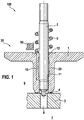
- Fig. 1 schematically shows the essential parts of a control valve 30 according to the invention in longitudinal section, which is arranged in the injector body 50 of a fuel injector 100 .
- the control valve 30 has a valve sleeve 1, a guide pin 2, a valve piece 3 and a closing spring 5 .
- the closing spring 5 presses the valve sleeve 1 against a formed on the valve member 3 valve seat 4.
- a force can be applied to the valve sleeve 1, by lifting the valve sleeve 1 from the valve seat 4, and so a gap frees .
- a force can be applied to the valve sleeve 1, by lifting the valve sleeve 1 from the valve seat 4, and so a gap frees .
- fuel from a control chamber 7, which is bounded by the valve piece 3 on the side facing away from the valve sleeve 1 , via a valve disposed in the 3 piece bore 8 and flow through the released gap in the low-pressure chamber 9 , which surrounds the valve sleeve 1 and connected to the not shown return system of the fuel injector 100 .
- the opening movement of a not shown nozzle needle of the fuel injector 100 can be controlled.
- the valve sleeve 1 is guided over a guide region 15 on the guide pin 2 .
- the guide portion 15 has on the one hand, the valve sleeve 1, a guide surface of the valve sleeve 11 and the other part of the guide pins 2, a guide surface of the guide pin 12.
- the guide surface of the valve sleeve 11, an undercut 20 is formed so that upon bending of the guide pin 2, a contact between the valve sleeve 1 and guide pin 2 in the middle of the guide portion 15 is avoided.
- valve sleeve 1 is additionally guided in the appropriately designed valve piece 3 .
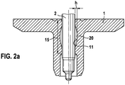
- Fig. 2a shows an advantageous embodiment of the formed in the valve sleeve 1 undercut 20 as a concave arc with the height h.
- the undercut 20 is formed over most of the guide portion 15 .
- the processing of the undercut 20 is incorporated into an existing grinding process for the guide surface of the valve sleeve 11 .
- the height h of the concave arc is ideally 1 .mu.m to 10 .mu.m.
Landscapes
- Engineering & Computer Science (AREA)
- Chemical & Material Sciences (AREA)
- Combustion & Propulsion (AREA)
- Mechanical Engineering (AREA)
- General Engineering & Computer Science (AREA)
- Fuel-Injection Apparatus (AREA)
Description
- Die Erfindung betrifft ein druckausgeglichenes Steuerventil für einen Kraftstoffinjektor einer Brennkraftmaschine mit den Merkmalen des Oberbegriffs von Anspruch 1.
- Ein druckausgeglichenes Steuerventil für einen Kraftstoffinjektor ist aus
DE 10 2007 047 425 A1 bekannt, bei dem eine Ventilhülse auf einem Führungsbolzen axial beweglich geführt ist. Die Ventilhülse begrenzt schaltbar eine Ventilkammer nach außen, die mit einem Steuerraum einer Düsennadel des Kraftstoffinjektors über eine Ablaufbohrung verbunden ist. Durch eine Schließfeder wird die Ventilhülse gegen einen an einem Ventilstück ausgebildeten Ventilsitz gepresst und verschließt dadurch die Ventilkammer gegenüber einem Niederdruckraum. Bei Betätigung einer Magnetspule hebt die Ventilhülse aufgrund elektromagnetischer Kräfte vom Ventilsitz ab. Über Ventilkammer und Ablaufbohrung wird so der Steuerraum mit dem Niederdruckraum verbunden, der Druck im Steuerraum fällt ab und die Düsennadel hebt vom Düsennadelsitz ab und gibt Einspritzöffnungen in den Brennraum einer Brennkraftmaschine frei. - Desweiteren ist aus
DE 10 2006 055 548 A1 ein druckausgeglichenes Steuerventil für einen Kraftstoffinjektor bekannt, bei dem eine Ventilhülse auf einem Führungsbolzen axial beweglich geführt ist. Die Ventilhülse begrenzt schaltbar eine Ventilkammer nach außen, die über Bohrungen im Führungsbolzen mit einem Steuerraum einer Düsennadel des Kraftstoffinjektors verbunden ist. Die Ventilhülse weist eine Ringnut auf, wobei sich die Ringnut an eine Dichtfläche anschließt, die mit einem Ventilsitz des Führungsbolzens zusammenwirkt. Durch eine Schließfeder wird die Ventilhülse schaltbar gegen den Ventilsitz des Führungsbolzens gepresst und verschließt dadurch die Ventilkammer gegenüber einem Niederdruckraum. Bei Betätigung einer Magnetspule hebt die Ventilhülse aufgrund elektromagnetischer Kräfte vom Ventilsitz ab. - Bei den Steuerventilen aus
DE 10 2007 047 425 A1 undDE 10 2006 055 548 A1 kann es aufgrund von Belagsbildungen im Führungsbereich an Führungsbolzen und/oder Ventilhülse, verursacht z.B. von Alterungspolymerbestandteilen oder Bioanteilen im Kraftstoff, zu Funktionsbeeinträchtigungen kommen. - Zur Vermeidung der Auswirkungen dieser Belagsbildungen ist aus
DE 10 2011 004 186 A1 bekannt, dass die Belagsbildung im Führungsbereich zwischen einem Führungselement und einem Bolzen reduziert wird. Dies wird erreicht, indem die Oberfläche des Bolzens im Führungsbereich strukturiert ausgeführt ist. - Weiterhin ist aus der
DE 10 2007 013 245 A1 bekannt, dass an der Ventilhülse benachbart zum Ventilsitz des Steuerventils ein Hinterstich ausgebildet werden kann, um die Druckbelastungen und Verformungen im Bereich des Ventilsitzes zu beeinflussen und den Verschleiß am Ventilsitz zu minimieren. - Aufgrund der gestiegenen Anforderungen eines Kraftstoffinjektors hinsichtlich der höheren Drücke des eingespritzten Kraftstoffs kann es jedoch zunehmend zu einer Durchbiegung des Führungsbolzens kommen. Die Folge ist, dass zusätzlich zur Belagsbildung erhöhte Verschleißgefahr in der Mitte des Führungsbereichs sowohl an Führungsbolzen als auch an Ventilhülse besteht.
- Das erfindungsgemäße Kraftstoffeinspritzventil mit den Merkmalen des Patentanspruchs 1 minimiert den Verschleiß zwischen Führungsbolzen und Ventilhülse. Dies wird dadurch erreicht, dass im Führungsbereich, in dem eine Führungsfläche der Ventilhülse und eine Führungsfläche des Führungsbolzens zusammenwirken, in der Führungsfläche der Ventilhülse ein Hinterstich ausgebildet ist.
- Somit unterteilt sich die resultierende Führung der Ventilhülse in zwei Bereiche entlang der Längsachse des Führungsbolzens, und an den beiden Enden des Führungsbereichs bleibt jeweils eine definierte Länge erhalten, an der ein Kontakt zwischen Führungsbolzen und Ventilhülse möglich ist. Eine Durchbiegung des Führungsbolzens kann dann keine punktuelle Berührung des Führungsbolzens mit der Ventilhülse in der Mitte des Führungsbereichs zur Folge haben.
- Wegen der Ausbildung des Hinterstichs an der Ventilhülse und nicht am Führungsbolzen selbst bleiben die definierten Längen an den Enden des Führungsbereichs über den gesamten Hub der Ventilhülse konstant. Kommt es dann zu einer Verkippung oder einer Durchbiegung des Führungsbolzens, ist die Tribologie im Kontakt Führungsbolzen zu Ventilhülse robuster.
Weiterhin bleiben aufgrund der Ausbildung des Hinterstichs an der Ventilhülse die beiden Leckagepfade an den beiden Enden des Führungsbereichs konstant. - In einer Ausführungsform ist der Hinterstich axial betrachtet zumindest näherungsweise in der Mitte des Führungsbereichs ausgebildet. Dadurch entstehen gleich große resultierende Führungen der Ventilhülse an den beiden Enden des Führungsbereichs. Die Vermeidung der punktuellen Berührung des Führungsbolzens mit der Ventilhülse bei Durchbiegung des Führungsbolzens ist so optimiert.
In einer weiteren Ausführungsform ist der Hinterstich radial umlaufend ausgebildet. Eine Rotation von Führungsbolzen oder Ventilhülse um ihre Längsachse hat damit keine negativen Auswirkungen mehr auf den Verschleiß; eine Verdrehsicherung ist nicht erforderlich.
In einer weiteren Ausführungsform ist der Hinterstich im Längsschnitt betrachtet als konkaver Bogen ausgeführt. Die Kontur des konkaven Bogens kann so einer potenziellen Durchbiegung des Führungsbolzens auf seiner ausbeulenden Seite angepasst werden. Bei einer Durchbiegung des Führungsbolzens würde es dann auf seiner ausbeulenden Seite zu einer annähernd konstanten Spalthöhe zwischen den Führungsflächen von Führungsbolzen und Ventilhülse kommen. Ein gleichmäßiger Schmierfilmaufbau wäre die Folge und damit auch minimierter Festkörperkontakt und minimierter Verschleiß in den beiden Führungsflächen. Ein bevorzugter Wert für die Höhe des konkaven Bogens ist 1 µm bis 10 µm. -
-
Fig. 1 zeigt einen Längsschnitt durch ein erfindungsgemäßes Steuerventil, wobei nur die wesentlichen Bereiche schematisch gezeigt sind. -
Fig. 2a zeigt einen Längsschnitt durch eine Ausführungsform der Ventilhülse, in dem der Hinterstich als konkaver Bogen ausgebildet ist. -
Fig. 1 zeigt schematisch die wesentlichen Teile eines erfindungsgemäßen Steuerventils 30 im Längsschnitt, das im Injektorkörper 50 eines Kraftstoffinjektors 100 angeordnet ist. Das Steuerventil 30 weist eine Ventilhülse 1, einen Führungsbolzen 2, ein Ventilstück 3 und eine Schließfeder 5 auf. - Die Schließfeder 5 drückt die Ventilhülse 1 gegen einen am Ventilstück 3 ausgebildeten Ventilsitz 4. Durch einen nicht dargestellten Aktor, z.B. einen Magneten, kann auf die Ventilhülse 1 eine Kraft aufgebracht werden, durch die die Ventilhülse 1 vom Ventilsitz 4 abhebt und so einen Spalt freigibt. Beispielsweise kann so unter Hochdruck stehender Kraftstoff von einem Steuerraum 7, der vom Ventilstück 3 auf der der Ventilhülse 1 abgewandten Seite begrenzt wird, über eine im Ventilstück 3 angeordnete Bohrung 8 und über den freigegebenen Spalt in den Niederdruckraum 9 fließen, der die Ventilhülse 1 umgibt und mit dem nicht dargestellten Rücklaufsystem des Kraftstoffinjektors 100 verbunden ist. Auf diese Weise kann z.B. die Öffnungsbewegung einer nicht dargestellten Düsennadel des Kraftstoffinjektors 100 gesteuert werden.
- Die Ventilhülse 1 wird über einen Führungsbereich 15 auf dem Führungsbolzen 2 geführt. Über den Führungsbereich 15 weist einerseits die Ventilhülse 1 eine Führungsfläche der Ventilhülse 11 auf und andererseits der Führungsbolzen 2 eine Führungsfläche des Führungsbolzens 12. Erfindungsgemäß ist an der Führungsfläche der Ventilhülse 11 ein Hinterstich 20 ausgebildet, so dass bei Biegung des Führungsbolzens 2 ein Kontakt zwischen Ventilhülse 1 und Führungsbolzen 2 in der Mitte des Führungsbereichs 15 vermieden wird.
- In anderen Ausgestaltungen wird die Ventilhülse 1 zusätzlich im entsprechend ausgebildeten Ventilstück 3 geführt.
-
Fig. 2a zeigt eine vorteilhafte Ausführung des in der Ventilhülse 1 ausgebildeten Hinterstichs 20 als konkaver Bogen mit der Höhe h. Der Hinterstich 20 ist über den größten Teil des Führungsbereichs 15 ausgebildet. Vorzugsweise wird die Bearbeitung des Hinterstichs 20 in einen bestehenden Schleifprozess für die Führungsfläche der Ventilhülse 11 eingebunden. Die Höhe h des konkaven Bogens beträgt dabei idealerweise 1 µm bis 10 µm.
Claims (4)
- Steuerventil 30 für einen Kraftstoffinjektor 100, das in einem Injektorkörper 50 angeordnet ist, mit einer im Steuerventil 30 angeordneten Ventilhülse 1, die axial beweglich auf einem Führungsbolzen 2 innerhalb eines Führungsbereichs 15 geführt ist, in dem eine Führungsfläche der Ventilhülse 11 und eine Führungsfläche des Führungsbolzens 12 zusammenwirken, wobei die Führungsfläche der Ventilhülse 11 einen Hinterstich 20 aufweist, dadurch gekennzeichnet, dass der Hinterstich 20 zumindest näherungsweise in der Mitte des Führungsbereichs 15 ausgebildet ist, wobei gleich große resultierende Führungen der Ventilhülse an den beiden Enden des Führungsbereichs ausgebildet sind, wobei der Hinterstich 20 im Längsschnitt als konkaver Bogen ausgeführt ist.
- Steuerventil 30 nach Anspruch 1, dadurch gekennzeichnet, dass der Hinterstich 20 radial umlaufend ist.
- Steuerventil 30 nach Anspruch 1 oder 2, dadurch gekennzeichnet, dass der konkave Bogen über den größten Teil des Führungsbereichs 15 verläuft.
- Steuerventil 30 nach einem der Ansprüche 1 bis 3, dadurch gekennzeichnet, dass der konkave Bogen eine Höhe h von 1 µm bis 10 µm besitzt.
Applications Claiming Priority (1)
| Application Number | Priority Date | Filing Date | Title |
|---|---|---|---|
| DE201310211855 DE102013211855A1 (de) | 2013-06-21 | 2013-06-21 | Steuerventil für einen Kraftstoffinjektor |
Publications (2)
| Publication Number | Publication Date |
|---|---|
| EP2816219A1 EP2816219A1 (de) | 2014-12-24 |
| EP2816219B1 true EP2816219B1 (de) | 2018-10-10 |
Family
ID=50440556
Family Applications (1)
| Application Number | Title | Priority Date | Filing Date |
|---|---|---|---|
| EP14163848.6A Not-in-force EP2816219B1 (de) | 2013-06-21 | 2014-04-08 | Steuerventil für einen Kraftstoffinjektor |
Country Status (2)
| Country | Link |
|---|---|
| EP (1) | EP2816219B1 (de) |
| DE (1) | DE102013211855A1 (de) |
Families Citing this family (4)
| Publication number | Priority date | Publication date | Assignee | Title |
|---|---|---|---|---|
| DE102015203515A1 (de) * | 2015-02-27 | 2016-09-01 | Robert Bosch Gmbh | Teildruckausgeglichenes Druckregelventil für einen Hochdruckspeicher |
| DE102015204515A1 (de) * | 2015-03-12 | 2016-09-15 | Robert Bosch Gmbh | Steuerventil für einen Kraftstoffinjektor |
| DE102015211043A1 (de) * | 2015-06-16 | 2016-12-22 | Robert Bosch Gmbh | Kraftstoffeinspritzventil für Brennkraftmaschinen |
| DE102015223168A1 (de) * | 2015-11-24 | 2017-05-24 | Robert Bosch Gmbh | Kraftstoffinjektor |
Family Cites Families (7)
| Publication number | Priority date | Publication date | Assignee | Title |
|---|---|---|---|---|
| DE102006021741A1 (de) * | 2006-05-10 | 2007-11-15 | Robert Bosch Gmbh | Kraftstoffinjektor mit druckausgeglichenem Steuerventil |
| DE102006055548A1 (de) | 2006-11-24 | 2008-05-29 | Robert Bosch Gmbh | Kraftstoffinjektor |
| DE102007013245A1 (de) * | 2007-03-20 | 2008-09-25 | Robert Bosch Gmbh | Druckausgeglichenes Schaltventil |
| DE102007040248A1 (de) * | 2007-08-27 | 2009-03-05 | Robert Bosch Gmbh | Steuerventil für einen Kraftstoffinjektor |
| DE102007047425A1 (de) | 2007-10-04 | 2009-04-09 | Robert Bosch Gmbh | Steuerventil für einen Kraftstoffinjektor |
| DE102009029009A1 (de) * | 2009-08-31 | 2011-03-03 | Robert Bosch Gmbh | Injektor zum Einspritzen von Kraftstoff |
| DE102011004186A1 (de) | 2011-02-16 | 2012-08-16 | Robert Bosch Gmbh | Kraftstoffeinspritzkomponente |
-
2013
- 2013-06-21 DE DE201310211855 patent/DE102013211855A1/de not_active Withdrawn
-
2014
- 2014-04-08 EP EP14163848.6A patent/EP2816219B1/de not_active Not-in-force
Non-Patent Citations (1)
| Title |
|---|
| None * |
Also Published As
| Publication number | Publication date |
|---|---|
| EP2816219A1 (de) | 2014-12-24 |
| DE102013211855A1 (de) | 2014-12-24 |
Similar Documents
| Publication | Publication Date | Title |
|---|---|---|
| EP2906815B1 (de) | Ventil für eine pumpe | |
| EP1567765B1 (de) | Einspritzventil | |
| WO2008061844A1 (de) | Kraftstoffinjektor | |
| EP2816219A1 (de) | Steuerventil für einen Kraftstoffinjektor | |
| DE102008035087B4 (de) | Einspritzventil | |
| WO2014000961A1 (de) | Kraftstoffinjektor mit magnetaktor | |
| DE102014217441A1 (de) | Elektromagnetisch betätigbares Proportionalventil | |
| DE102016211679A1 (de) | Elektromagnetisch betätigbares Einlassventil und Hochdruckpumpe mit Einlassventil | |
| WO2017012730A1 (de) | Kraftstoffinjektor und verfahren zur herstellung eines kraftstoffinjektors | |
| WO2019233662A1 (de) | Elektromagnetisch betätigbares saugventil und kraftstoff-hochdruckpumpe | |
| EP2798192B1 (de) | Kraftstoffeinspritzventil für brennkraftmaschinen | |
| EP2630361B1 (de) | Kraftstoffinjektor | |
| DE102009026564A1 (de) | Kraftstoff-Injektor mit druckausgeglichenem Steuerventil | |
| WO2007104590A1 (de) | Kraftstoffeinspritzventil für brennkraftmaschinen | |
| EP2016276B1 (de) | Kraftstoffinjektor mit optimiertem rücklauf | |
| DE10050599B4 (de) | Einspritzventil mit einem Pumpkolben | |
| EP2957760B1 (de) | Düsenbaugruppe für einen kraftstoffinjektor sowie kraftstoffinjektor | |
| EP2960487B1 (de) | Kraftstoffeinspritzventil für brennkraftmaschinen | |
| EP2256332A2 (de) | Kraftstoffinjektor mit Druckverstärkerkolben | |
| WO2008046677A2 (de) | Kraftstoffinjektor mit abdichtelement | |
| WO2016134930A1 (de) | Teildruckausgeglichenes druckregelventil für einen hochdruckspeicher | |
| DE102015214269A1 (de) | Elektromagnetisch betätigbares Saugventil für eine Hochdruckpumpe sowie Hochdruckpumpe | |
| EP2726731B1 (de) | Kraftstoffinjektor | |
| DE102012205696A1 (de) | Kraftstoffinjektor, insbesondere Common-Rail-Injektor | |
| DE102007038138A1 (de) | Steuerventil für einen Kraftstoffinjektor |
Legal Events
| Date | Code | Title | Description |
|---|---|---|---|
| PUAI | Public reference made under article 153(3) epc to a published international application that has entered the european phase |
Free format text: ORIGINAL CODE: 0009012 |
|
| 17P | Request for examination filed |
Effective date: 20140408 |
|
| AK | Designated contracting states |
Kind code of ref document: A1 Designated state(s): AL AT BE BG CH CY CZ DE DK EE ES FI FR GB GR HR HU IE IS IT LI LT LU LV MC MK MT NL NO PL PT RO RS SE SI SK SM TR |
|
| AX | Request for extension of the european patent |
Extension state: BA ME |
|
| R17P | Request for examination filed (corrected) |
Effective date: 20150624 |
|
| RBV | Designated contracting states (corrected) |
Designated state(s): AL AT BE BG CH CY CZ DE DK EE ES FI FR GB GR HR HU IE IS IT LI LT LU LV MC MK MT NL NO PL PT RO RS SE SI SK SM TR |
|
| STAA | Information on the status of an ep patent application or granted ep patent |
Free format text: STATUS: EXAMINATION IS IN PROGRESS |
|
| 17Q | First examination report despatched |
Effective date: 20170714 |
|
| GRAP | Despatch of communication of intention to grant a patent |
Free format text: ORIGINAL CODE: EPIDOSNIGR1 |
|
| STAA | Information on the status of an ep patent application or granted ep patent |
Free format text: STATUS: GRANT OF PATENT IS INTENDED |
|
| INTG | Intention to grant announced |
Effective date: 20180706 |
|
| GRAS | Grant fee paid |
Free format text: ORIGINAL CODE: EPIDOSNIGR3 |
|
| GRAA | (expected) grant |
Free format text: ORIGINAL CODE: 0009210 |
|
| STAA | Information on the status of an ep patent application or granted ep patent |
Free format text: STATUS: THE PATENT HAS BEEN GRANTED |
|
| AK | Designated contracting states |
Kind code of ref document: B1 Designated state(s): AL AT BE BG CH CY CZ DE DK EE ES FI FR GB GR HR HU IE IS IT LI LT LU LV MC MK MT NL NO PL PT RO RS SE SI SK SM TR |
|
| REG | Reference to a national code |
Ref country code: GB Ref legal event code: FG4D Free format text: NOT ENGLISH |
|
| REG | Reference to a national code |
Ref country code: CH Ref legal event code: EP Ref country code: AT Ref legal event code: REF Ref document number: 1051536 Country of ref document: AT Kind code of ref document: T Effective date: 20181015 |
|
| REG | Reference to a national code |
Ref country code: IE Ref legal event code: FG4D Free format text: LANGUAGE OF EP DOCUMENT: GERMAN |
|
| REG | Reference to a national code |
Ref country code: DE Ref legal event code: R096 Ref document number: 502014009673 Country of ref document: DE |
|
| REG | Reference to a national code |
Ref country code: NL Ref legal event code: MP Effective date: 20181010 |
|
| REG | Reference to a national code |
Ref country code: LT Ref legal event code: MG4D |
|
| PG25 | Lapsed in a contracting state [announced via postgrant information from national office to epo] |
Ref country code: NL Free format text: LAPSE BECAUSE OF FAILURE TO SUBMIT A TRANSLATION OF THE DESCRIPTION OR TO PAY THE FEE WITHIN THE PRESCRIBED TIME-LIMIT Effective date: 20181010 |
|
| PG25 | Lapsed in a contracting state [announced via postgrant information from national office to epo] |
Ref country code: FI Free format text: LAPSE BECAUSE OF FAILURE TO SUBMIT A TRANSLATION OF THE DESCRIPTION OR TO PAY THE FEE WITHIN THE PRESCRIBED TIME-LIMIT Effective date: 20181010 Ref country code: IS Free format text: LAPSE BECAUSE OF FAILURE TO SUBMIT A TRANSLATION OF THE DESCRIPTION OR TO PAY THE FEE WITHIN THE PRESCRIBED TIME-LIMIT Effective date: 20190210 Ref country code: NO Free format text: LAPSE BECAUSE OF FAILURE TO SUBMIT A TRANSLATION OF THE DESCRIPTION OR TO PAY THE FEE WITHIN THE PRESCRIBED TIME-LIMIT Effective date: 20190110 Ref country code: ES Free format text: LAPSE BECAUSE OF FAILURE TO SUBMIT A TRANSLATION OF THE DESCRIPTION OR TO PAY THE FEE WITHIN THE PRESCRIBED TIME-LIMIT Effective date: 20181010 Ref country code: LV Free format text: LAPSE BECAUSE OF FAILURE TO SUBMIT A TRANSLATION OF THE DESCRIPTION OR TO PAY THE FEE WITHIN THE PRESCRIBED TIME-LIMIT Effective date: 20181010 Ref country code: HR Free format text: LAPSE BECAUSE OF FAILURE TO SUBMIT A TRANSLATION OF THE DESCRIPTION OR TO PAY THE FEE WITHIN THE PRESCRIBED TIME-LIMIT Effective date: 20181010 Ref country code: LT Free format text: LAPSE BECAUSE OF FAILURE TO SUBMIT A TRANSLATION OF THE DESCRIPTION OR TO PAY THE FEE WITHIN THE PRESCRIBED TIME-LIMIT Effective date: 20181010 Ref country code: PL Free format text: LAPSE BECAUSE OF FAILURE TO SUBMIT A TRANSLATION OF THE DESCRIPTION OR TO PAY THE FEE WITHIN THE PRESCRIBED TIME-LIMIT Effective date: 20181010 Ref country code: BG Free format text: LAPSE BECAUSE OF FAILURE TO SUBMIT A TRANSLATION OF THE DESCRIPTION OR TO PAY THE FEE WITHIN THE PRESCRIBED TIME-LIMIT Effective date: 20190110 |
|
| PG25 | Lapsed in a contracting state [announced via postgrant information from national office to epo] |
Ref country code: PT Free format text: LAPSE BECAUSE OF FAILURE TO SUBMIT A TRANSLATION OF THE DESCRIPTION OR TO PAY THE FEE WITHIN THE PRESCRIBED TIME-LIMIT Effective date: 20190210 Ref country code: GR Free format text: LAPSE BECAUSE OF FAILURE TO SUBMIT A TRANSLATION OF THE DESCRIPTION OR TO PAY THE FEE WITHIN THE PRESCRIBED TIME-LIMIT Effective date: 20190111 Ref country code: SE Free format text: LAPSE BECAUSE OF FAILURE TO SUBMIT A TRANSLATION OF THE DESCRIPTION OR TO PAY THE FEE WITHIN THE PRESCRIBED TIME-LIMIT Effective date: 20181010 Ref country code: AL Free format text: LAPSE BECAUSE OF FAILURE TO SUBMIT A TRANSLATION OF THE DESCRIPTION OR TO PAY THE FEE WITHIN THE PRESCRIBED TIME-LIMIT Effective date: 20181010 Ref country code: RS Free format text: LAPSE BECAUSE OF FAILURE TO SUBMIT A TRANSLATION OF THE DESCRIPTION OR TO PAY THE FEE WITHIN THE PRESCRIBED TIME-LIMIT Effective date: 20181010 |
|
| REG | Reference to a national code |
Ref country code: DE Ref legal event code: R097 Ref document number: 502014009673 Country of ref document: DE |
|
| PG25 | Lapsed in a contracting state [announced via postgrant information from national office to epo] |
Ref country code: CZ Free format text: LAPSE BECAUSE OF FAILURE TO SUBMIT A TRANSLATION OF THE DESCRIPTION OR TO PAY THE FEE WITHIN THE PRESCRIBED TIME-LIMIT Effective date: 20181010 Ref country code: DK Free format text: LAPSE BECAUSE OF FAILURE TO SUBMIT A TRANSLATION OF THE DESCRIPTION OR TO PAY THE FEE WITHIN THE PRESCRIBED TIME-LIMIT Effective date: 20181010 |
|
| PLBE | No opposition filed within time limit |
Free format text: ORIGINAL CODE: 0009261 |
|
| STAA | Information on the status of an ep patent application or granted ep patent |
Free format text: STATUS: NO OPPOSITION FILED WITHIN TIME LIMIT |
|
| PG25 | Lapsed in a contracting state [announced via postgrant information from national office to epo] |
Ref country code: EE Free format text: LAPSE BECAUSE OF FAILURE TO SUBMIT A TRANSLATION OF THE DESCRIPTION OR TO PAY THE FEE WITHIN THE PRESCRIBED TIME-LIMIT Effective date: 20181010 Ref country code: SM Free format text: LAPSE BECAUSE OF FAILURE TO SUBMIT A TRANSLATION OF THE DESCRIPTION OR TO PAY THE FEE WITHIN THE PRESCRIBED TIME-LIMIT Effective date: 20181010 Ref country code: SK Free format text: LAPSE BECAUSE OF FAILURE TO SUBMIT A TRANSLATION OF THE DESCRIPTION OR TO PAY THE FEE WITHIN THE PRESCRIBED TIME-LIMIT Effective date: 20181010 Ref country code: RO Free format text: LAPSE BECAUSE OF FAILURE TO SUBMIT A TRANSLATION OF THE DESCRIPTION OR TO PAY THE FEE WITHIN THE PRESCRIBED TIME-LIMIT Effective date: 20181010 |
|
| 26N | No opposition filed |
Effective date: 20190711 |
|
| PG25 | Lapsed in a contracting state [announced via postgrant information from national office to epo] |
Ref country code: SI Free format text: LAPSE BECAUSE OF FAILURE TO SUBMIT A TRANSLATION OF THE DESCRIPTION OR TO PAY THE FEE WITHIN THE PRESCRIBED TIME-LIMIT Effective date: 20181010 |
|
| REG | Reference to a national code |
Ref country code: CH Ref legal event code: PL |
|
| REG | Reference to a national code |
Ref country code: BE Ref legal event code: MM Effective date: 20190430 |
|
| GBPC | Gb: european patent ceased through non-payment of renewal fee |
Effective date: 20190408 |
|
| PG25 | Lapsed in a contracting state [announced via postgrant information from national office to epo] |
Ref country code: MC Free format text: LAPSE BECAUSE OF FAILURE TO SUBMIT A TRANSLATION OF THE DESCRIPTION OR TO PAY THE FEE WITHIN THE PRESCRIBED TIME-LIMIT Effective date: 20181010 Ref country code: LU Free format text: LAPSE BECAUSE OF NON-PAYMENT OF DUE FEES Effective date: 20190408 |
|
| PG25 | Lapsed in a contracting state [announced via postgrant information from national office to epo] |
Ref country code: GB Free format text: LAPSE BECAUSE OF NON-PAYMENT OF DUE FEES Effective date: 20190408 Ref country code: LI Free format text: LAPSE BECAUSE OF NON-PAYMENT OF DUE FEES Effective date: 20190430 Ref country code: CH Free format text: LAPSE BECAUSE OF NON-PAYMENT OF DUE FEES Effective date: 20190430 |
|
| PG25 | Lapsed in a contracting state [announced via postgrant information from national office to epo] |
Ref country code: BE Free format text: LAPSE BECAUSE OF NON-PAYMENT OF DUE FEES Effective date: 20190430 |
|
| PG25 | Lapsed in a contracting state [announced via postgrant information from national office to epo] |
Ref country code: TR Free format text: LAPSE BECAUSE OF FAILURE TO SUBMIT A TRANSLATION OF THE DESCRIPTION OR TO PAY THE FEE WITHIN THE PRESCRIBED TIME-LIMIT Effective date: 20181010 |
|
| PG25 | Lapsed in a contracting state [announced via postgrant information from national office to epo] |
Ref country code: IE Free format text: LAPSE BECAUSE OF NON-PAYMENT OF DUE FEES Effective date: 20190408 |
|
| REG | Reference to a national code |
Ref country code: AT Ref legal event code: MM01 Ref document number: 1051536 Country of ref document: AT Kind code of ref document: T Effective date: 20190408 |
|
| PG25 | Lapsed in a contracting state [announced via postgrant information from national office to epo] |
Ref country code: AT Free format text: LAPSE BECAUSE OF NON-PAYMENT OF DUE FEES Effective date: 20190408 |
|
| PG25 | Lapsed in a contracting state [announced via postgrant information from national office to epo] |
Ref country code: CY Free format text: LAPSE BECAUSE OF FAILURE TO SUBMIT A TRANSLATION OF THE DESCRIPTION OR TO PAY THE FEE WITHIN THE PRESCRIBED TIME-LIMIT Effective date: 20181010 |
|
| PG25 | Lapsed in a contracting state [announced via postgrant information from national office to epo] |
Ref country code: MT Free format text: LAPSE BECAUSE OF FAILURE TO SUBMIT A TRANSLATION OF THE DESCRIPTION OR TO PAY THE FEE WITHIN THE PRESCRIBED TIME-LIMIT Effective date: 20181010 Ref country code: HU Free format text: LAPSE BECAUSE OF FAILURE TO SUBMIT A TRANSLATION OF THE DESCRIPTION OR TO PAY THE FEE WITHIN THE PRESCRIBED TIME-LIMIT; INVALID AB INITIO Effective date: 20140408 |
|
| PG25 | Lapsed in a contracting state [announced via postgrant information from national office to epo] |
Ref country code: MK Free format text: LAPSE BECAUSE OF FAILURE TO SUBMIT A TRANSLATION OF THE DESCRIPTION OR TO PAY THE FEE WITHIN THE PRESCRIBED TIME-LIMIT Effective date: 20181010 |
|
| PGFP | Annual fee paid to national office [announced via postgrant information from national office to epo] |
Ref country code: IT Payment date: 20220429 Year of fee payment: 9 Ref country code: FR Payment date: 20220420 Year of fee payment: 9 |
|
| PGFP | Annual fee paid to national office [announced via postgrant information from national office to epo] |
Ref country code: DE Payment date: 20220627 Year of fee payment: 9 |
|
| REG | Reference to a national code |
Ref country code: DE Ref legal event code: R119 Ref document number: 502014009673 Country of ref document: DE |
|
| PG25 | Lapsed in a contracting state [announced via postgrant information from national office to epo] |
Ref country code: FR Free format text: LAPSE BECAUSE OF NON-PAYMENT OF DUE FEES Effective date: 20230430 Ref country code: DE Free format text: LAPSE BECAUSE OF NON-PAYMENT OF DUE FEES Effective date: 20231103 |
|
| PG25 | Lapsed in a contracting state [announced via postgrant information from national office to epo] |
Ref country code: IT Free format text: LAPSE BECAUSE OF NON-PAYMENT OF DUE FEES Effective date: 20230408 |