EP2816201B1 - Single-casing steam turbine and single-shaft combined-cycle power generation apparatus - Google Patents
Single-casing steam turbine and single-shaft combined-cycle power generation apparatus Download PDFInfo
- Publication number
- EP2816201B1 EP2816201B1 EP12868914.8A EP12868914A EP2816201B1 EP 2816201 B1 EP2816201 B1 EP 2816201B1 EP 12868914 A EP12868914 A EP 12868914A EP 2816201 B1 EP2816201 B1 EP 2816201B1
- Authority
- EP
- European Patent Office
- Prior art keywords
- pressure chamber
- steam turbine
- casing
- rotor
- pressure
- Prior art date
- Legal status (The legal status is an assumption and is not a legal conclusion. Google has not performed a legal analysis and makes no representation as to the accuracy of the status listed.)
- Active
Links
- 238000010248 power generation Methods 0.000 title 1
- 238000001514 detection method Methods 0.000 claims description 9
- 238000007789 sealing Methods 0.000 claims description 4
- 230000007423 decrease Effects 0.000 description 18
- 238000004326 stimulated echo acquisition mode for imaging Methods 0.000 description 7
- 238000011084 recovery Methods 0.000 description 5
- 238000010586 diagram Methods 0.000 description 4
- XLYOFNOQVPJJNP-UHFFFAOYSA-N water Substances O XLYOFNOQVPJJNP-UHFFFAOYSA-N 0.000 description 3
- 230000003247 decreasing effect Effects 0.000 description 2
- RLQJEEJISHYWON-UHFFFAOYSA-N flonicamid Chemical compound FC(F)(F)C1=CC=NC=C1C(=O)NCC#N RLQJEEJISHYWON-UHFFFAOYSA-N 0.000 description 2
- 230000004323 axial length Effects 0.000 description 1
- 230000000694 effects Effects 0.000 description 1
- 238000007689 inspection Methods 0.000 description 1
- 239000000463 material Substances 0.000 description 1
- 238000000034 method Methods 0.000 description 1
- 230000002265 prevention Effects 0.000 description 1
Images


Classifications
-
- F—MECHANICAL ENGINEERING; LIGHTING; HEATING; WEAPONS; BLASTING
- F01—MACHINES OR ENGINES IN GENERAL; ENGINE PLANTS IN GENERAL; STEAM ENGINES
- F01D—NON-POSITIVE DISPLACEMENT MACHINES OR ENGINES, e.g. STEAM TURBINES
- F01D25/00—Component parts, details, or accessories, not provided for in, or of interest apart from, other groups
- F01D25/28—Supporting or mounting arrangements, e.g. for turbine casing
-
- F—MECHANICAL ENGINEERING; LIGHTING; HEATING; WEAPONS; BLASTING
- F01—MACHINES OR ENGINES IN GENERAL; ENGINE PLANTS IN GENERAL; STEAM ENGINES
- F01K—STEAM ENGINE PLANTS; STEAM ACCUMULATORS; ENGINE PLANTS NOT OTHERWISE PROVIDED FOR; ENGINES USING SPECIAL WORKING FLUIDS OR CYCLES
- F01K23/00—Plants characterised by more than one engine delivering power external to the plant, the engines being driven by different fluids
- F01K23/02—Plants characterised by more than one engine delivering power external to the plant, the engines being driven by different fluids the engine cycles being thermally coupled
- F01K23/06—Plants characterised by more than one engine delivering power external to the plant, the engines being driven by different fluids the engine cycles being thermally coupled combustion heat from one cycle heating the fluid in another cycle
- F01K23/10—Plants characterised by more than one engine delivering power external to the plant, the engines being driven by different fluids the engine cycles being thermally coupled combustion heat from one cycle heating the fluid in another cycle with exhaust fluid of one cycle heating the fluid in another cycle
-
- F—MECHANICAL ENGINEERING; LIGHTING; HEATING; WEAPONS; BLASTING
- F01—MACHINES OR ENGINES IN GENERAL; ENGINE PLANTS IN GENERAL; STEAM ENGINES
- F01K—STEAM ENGINE PLANTS; STEAM ACCUMULATORS; ENGINE PLANTS NOT OTHERWISE PROVIDED FOR; ENGINES USING SPECIAL WORKING FLUIDS OR CYCLES
- F01K23/00—Plants characterised by more than one engine delivering power external to the plant, the engines being driven by different fluids
- F01K23/12—Plants characterised by more than one engine delivering power external to the plant, the engines being driven by different fluids the engines being mechanically coupled
- F01K23/14—Plants characterised by more than one engine delivering power external to the plant, the engines being driven by different fluids the engines being mechanically coupled including at least one combustion engine
-
- F—MECHANICAL ENGINEERING; LIGHTING; HEATING; WEAPONS; BLASTING
- F02—COMBUSTION ENGINES; HOT-GAS OR COMBUSTION-PRODUCT ENGINE PLANTS
- F02C—GAS-TURBINE PLANTS; AIR INTAKES FOR JET-PROPULSION PLANTS; CONTROLLING FUEL SUPPLY IN AIR-BREATHING JET-PROPULSION PLANTS
- F02C6/00—Plural gas-turbine plants; Combinations of gas-turbine plants with other apparatus; Adaptations of gas-turbine plants for special use
- F02C6/18—Plural gas-turbine plants; Combinations of gas-turbine plants with other apparatus; Adaptations of gas-turbine plants for special use using the waste heat of gas-turbine plants outside the plants themselves, e.g. gas-turbine power heat plants
-
- F—MECHANICAL ENGINEERING; LIGHTING; HEATING; WEAPONS; BLASTING
- F02—COMBUSTION ENGINES; HOT-GAS OR COMBUSTION-PRODUCT ENGINE PLANTS
- F02C—GAS-TURBINE PLANTS; AIR INTAKES FOR JET-PROPULSION PLANTS; CONTROLLING FUEL SUPPLY IN AIR-BREATHING JET-PROPULSION PLANTS
- F02C7/00—Features, components parts, details or accessories, not provided for in, or of interest apart form groups F02C1/00 - F02C6/00; Air intakes for jet-propulsion plants
- F02C7/28—Arrangement of seals
-
- F—MECHANICAL ENGINEERING; LIGHTING; HEATING; WEAPONS; BLASTING
- F01—MACHINES OR ENGINES IN GENERAL; ENGINE PLANTS IN GENERAL; STEAM ENGINES
- F01D—NON-POSITIVE DISPLACEMENT MACHINES OR ENGINES, e.g. STEAM TURBINES
- F01D25/00—Component parts, details, or accessories, not provided for in, or of interest apart from, other groups
- F01D25/24—Casings; Casing parts, e.g. diaphragms, casing fastenings
- F01D25/243—Flange connections; Bolting arrangements
-
- F—MECHANICAL ENGINEERING; LIGHTING; HEATING; WEAPONS; BLASTING
- F02—COMBUSTION ENGINES; HOT-GAS OR COMBUSTION-PRODUCT ENGINE PLANTS
- F02C—GAS-TURBINE PLANTS; AIR INTAKES FOR JET-PROPULSION PLANTS; CONTROLLING FUEL SUPPLY IN AIR-BREATHING JET-PROPULSION PLANTS
- F02C6/00—Plural gas-turbine plants; Combinations of gas-turbine plants with other apparatus; Adaptations of gas-turbine plants for special use
- F02C6/02—Plural gas-turbine plants having a common power output
-
- F—MECHANICAL ENGINEERING; LIGHTING; HEATING; WEAPONS; BLASTING
- F05—INDEXING SCHEMES RELATING TO ENGINES OR PUMPS IN VARIOUS SUBCLASSES OF CLASSES F01-F04
- F05D—INDEXING SCHEME FOR ASPECTS RELATING TO NON-POSITIVE-DISPLACEMENT MACHINES OR ENGINES, GAS-TURBINES OR JET-PROPULSION PLANTS
- F05D2220/00—Application
- F05D2220/30—Application in turbines
- F05D2220/31—Application in turbines in steam turbines
-
- Y—GENERAL TAGGING OF NEW TECHNOLOGICAL DEVELOPMENTS; GENERAL TAGGING OF CROSS-SECTIONAL TECHNOLOGIES SPANNING OVER SEVERAL SECTIONS OF THE IPC; TECHNICAL SUBJECTS COVERED BY FORMER USPC CROSS-REFERENCE ART COLLECTIONS [XRACs] AND DIGESTS
- Y02—TECHNOLOGIES OR APPLICATIONS FOR MITIGATION OR ADAPTATION AGAINST CLIMATE CHANGE
- Y02E—REDUCTION OF GREENHOUSE GAS [GHG] EMISSIONS, RELATED TO ENERGY GENERATION, TRANSMISSION OR DISTRIBUTION
- Y02E20/00—Combustion technologies with mitigation potential
- Y02E20/16—Combined cycle power plant [CCPP], or combined cycle gas turbine [CCGT]
Definitions
- a present disclosure relates to a single-casing steam turbine and a single-shaft combined-cycle power plant using the single-casing steam turbine that are used in a power generating station or the like.
- a single-casing steam turbine e.g. single-casing reheat turbine: SRT
- SRT single-casing reheat turbine
- a low-pressure chamber being the heaviest is fixed by an anchor and the overall casing (particularly, the high-pressure chamber and the intermediate-pressure chamber) is allowed to thermally extend freely from the anchor so as to prevent thermal deformation.
- the rotor thermally extends from a thrust bearing which rotatably supports the rotor.
- the high-pressure chamber is inevitably arranged on a side farther from the thrust bearing.
- the thermal extension difference between the high-pressure chamber and the rotor increases.
- the large clearance between the rotary part and the stationary part in the high-pressure chamber leads to a decrease in performance of high-pressure blade rows.
- a blade skeleton of the high-pressure blade rows housed in the high-pressure chamber is particularly small and thus the increased clearance between the rotary part and the stationary part in the high-pressure chamber leads to major decline in the performance of the high-pressure blade rows.
- a combined-cycle power plant with a combination of a steam turbine and a gas turbine is in the spotlight as a power plant used for a thermal power station and the like.
- the combined-cycle power plant includes a single-shaft power plant in which the steam turbine and the gas turbine are coupled on the same shaft to drive a common generator.
- a single-shaft combined-cycle power plant using a single-casing steam turbine has become one of today's mainstream power plants with increasing length of end blades in recent years.
- the thrust bearing is arranged between the steam turbine and the gas turbine and the rotor thermally extends from the thrust bearing.
- the low-pressure chamber fixed by the anchor from which the casing thermally extends is arranged on the side closer to the thrust bearing from which the rotor thermally extends, i.e. toward the gas turbine.
- the combined-cycle power plant is normally arranged in a large-scale thermal power station and the steam turbine is axially large in length. Therefore, in the combined-cycle power plant using the single-casing steam turbine, it is necessary to set the clearance considerably large between the rotary part and the stationary part in the high-pressure chamber and thus the issue of the performance decline of the high-pressure blade rows tends to occur.
- JP 59-18207 A discloses a space-adjusting unit for adjusting the space between the stationary part and the rotary part of the steam turbine although this is not intended for use in the single-casing steam turbine.
- axial shifting of a flange part projecting from the rotor is detected by an extension difference detector and the casing of the steam turbine is moved by a hydraulic jack based on a detection signal from the extension difference detector.
- DE 3941089 A1 discloses an air sealing for opposing flanges, wherein a groove forms a gas channel, to avoid undesired gas-leakage between the flanges.
- JP H04 132 805 A teaches the improvement of turbine efficiency and the prevention of elongation of a casing and drop in critical space in the rotor by installing a handling means shifting the casing and a controlling means so as to have an elongative difference between the rotor and the casing due to thermal expansion at time of operating a low-pressure turbine.
- JP S59 18207 A discloses a steam turbine having an outer casing and an inner casing, wherein an extension difference between the outer casing and the inner casing during a turbine operation is detected, then a casing is moved in its location within a required range.
- JP H10 169408 relates to the seal structure of a casing in a steam turbine of double casing structure intended for high-pressure turbine stage of a reheat steam turbine.
- the space-adjusting unit described in JP 59-18207 A is not intended for use in the single-casing steam turbine having high-pressure blade rows and low-pressure blade rows housed in a single casing.
- issue such as an increased size of a hydraulic unit for moving the casing using the hydraulic jack in the same manner as the space-adjusting unit of JP 59-18207 A .
- a single-casing steam turbine according to at least one embodiment of the present invention, comprises:
- single-casing steam turbine indicates a steam turbine having blade rows including at least high-pressure blade rows and low-pressure blade rows that are housed in a single casing
- high-pressure chamber indicates a part where blade rows excluding the low-pressure blade rows are housed.
- the single-casing steam turbine may include intermediate-pressure blade rows in addition to the high-pressure blade rows and the low-pressure blade rows.
- the high-pressure chamber houses the high-pressure blade rows and the intermediate-pressure blade rows.
- expansion joint indicates a joint that is capable of sealing an interior space of the casing and absorbing the thermal extension of the high/intermediate-pressure chamber and/or the low-pressure chamber.
- the expansion joint may be constituted of an elastic member or bellows, which can be deformed in response to the thermal extension.
- the high-pressure chamber can be arranged on the side closer to the thrust bearing from which the rotor thermally extends. More specifically, the high-pressure chamber is separated from the low-pressure chamber fixed by the anchor and thus the high-pressure chamber thermally expands independently. Thus, the high-pressure chamber can be arranged on the side closer to the thrust bearing without causing the casing and the rotor to thermally extend in opposite directions.
- the thermal extension difference between the high-pressure chamber and the rotor is suppressed and thus it is possible to reduce the clearance between the rotary part and the stationary part in the high-pressure chamber and to suppress the performance decline of the high-pressure blade rows.
- the single-casing steam turbine further comprises a position-adjusting unit for adjusting a position of the high-pressure chamber in an axial direction of a rotor.
- the position-adjusting unit By adjusting the position of the high-pressure chamber by means of the position-adjusting unit, even when the clearance between the rotary part and the stationary part is comparatively small in the high-pressure chamber, the thermal extension difference between the high-pressure chamber and the rotor can be canceled out. Therefore, the rotary part and the stationary part are prevented from contacting each other. As a result, it is possible to further reduce the clearance between the rotary part and the stationary part in the high-pressure chamber and to reliably suppress the performance decline of the high-pressure blade rows.
- the thermal extension difference between the high-pressure chamber and the rotor can be offset and the rotary part and the stationary part are prevented from contacting each other. Therefore, even in the case where the low-pressure chamber fixed by the anchor is arranged on the side closer to the thrust bearing, from which the rotor thermally extends, in the manner similar to the conventional case, it is possible to reduce the clearance between the rotary part and the stationary part in the high-pressure chamber and to reliably suppress the performance decline of the high-pressure blade rows.
- the position of the high-pressure chamber can be adjusted by the position-adjusting unit as the low-pressure chamber being the heaviest section is separated from the high-pressure chamber in the above single-casing steam turbine. More specifically, it is possible to easily adjust the position of the high-pressure chamber, which is relatively lightweight, as a single unit using a position-adjusting unit constituted by known actuators such as hydraulic jacks.
- the position-adjusting unit comprises:
- the hydraulic cylinder to be used is switched by the switching valve so as to move the high-pressure chamber backward and forward along the axial direction of the rotor.
- the above single-casing steam turbine further comprises:
- the rotor may include, in the outside of a casing of the steam turbine, a disk part where the rotor has a shaft diameter different from the rest of the rotor or a taper surface where the rotor changes in diameter, and the detection unit may include a sensor for measuring a distance to an end surface of the disk part or the taper surface of the rotor.
- a single-shaft combined cycle power plant comprises a generator, the single-casing steam turbine described above, a gas turbine that are coupled in this order.
- a thrust bearing is provided between the gas turbine and the steam turbine, the high-pressure chamber is arranged closer to the thrust bearing than the low-pressure chamber in a casing of the steam turbine, and the low-pressure chamber is fixed by an anchor.
- the high-pressure chamber is arranged on the side closer to the thrust bearing from which the rotor thermally extends and thus the thermal extension difference between the high-pressure chamber and the rotor can be suppressed. Therefore, it is possible to suppress the performance decline of the high-pressure blade rows by reducing the clearance between the rotary part and the stationary part in the high-pressure chamber.
- the high-pressure chamber can be arranged on the side closer to the thrust bearing in the above manner, as the low-pressure chamber fixed by the anchor and the high-pressure chamber are separated and the arrangement of the high-pressure chamber on the side closer to the thrust bearing does not cause the casing and the rotor to thermally extend in opposite directions.
- a position-adjusting unit is provided for adjusting a position of the high-pressure chamber in the axial direction of the rotor.
- the position-adjusting unit By adjusting the position of the high-pressure chamber by means of the position-adjusting unit, even when the clearance between the rotary part and the stationary part is comparatively small in the high-pressure chamber, the thermal extension difference between the high-pressure chamber and the rotor can be canceled out. Therefore, the rotary part and the stationary part are prevented from contacting each other. As a result, it is possible to further reduce the clearance between the rotary part and the stationary part in the high-pressure chamber and to reliably suppress the performance decline of the high-pressure blade rows.
- a single-shaft combined cycle power plant comprises a generator, the single-casing steam turbine described above, and a gas turbine that are coupled in this order.
- a thrust bearing is provided between the gas turbine and the steam turbine, the low-pressure chamber is arranged closer to the thrust bearing than the high-pressure chamber in a casing of the steam turbine, the combined cycle power plant may further comprises a position-adjusting unit for adjusting a position of the high-pressure chamber in an axial direction of a rotor, and the low-pressure chamber is fixed by an anchor.
- the thermal extension difference between the high-pressure chamber and the rotor is canceled out so as to prevent the rotary part and the stationary part from contacting each other. Therefore, even in the case where the low-pressure chamber fixed by the anchor is arranged on the side closer to the thrust bearing from which the rotor thermally extends, it is still possible to reduce the clearance between the rotary part and the stationary part in the high-pressure chamber and to reliably suppress the performance decline of the high-pressure blade rows.
- the high-pressure chamber by connecting the high-pressure chamber and the low-pressure chamber by the expansion joint, the high-pressure chamber can be arranged on the side closer to the thrust bearing from which the rotor thermally extends. More specifically, the high-pressure chamber is separated from the low-pressure chamber fixed by the anchor and thus the high-pressure chamber thermally expands independently. Thus, the high-pressure chamber can be arranged on the side closer to the thrust bearing without causing the casing and the rotor to thermally extend in opposite directions.
- the thermal extension difference between the high-pressure chamber and the rotor is suppressed and thus it is possible to reduce the clearance between the rotary part and the stationary part in the high-pressure chamber and to suppress the performance decline of the high-pressure blade rows.
- the thermal extension difference between the high-pressure chamber and the rotor can be offset and the rotary part and the stationary part are prevented from contacting each other. Therefore, even in the case where the low-pressure chamber fixed by the anchor is arranged on the side closer to the thrust bearing, from which the rotor thermally extends, in the manner similar to the conventional case, it is possible to reduce the clearance between the rotary part and the stationary part in the high-pressure chamber and to reliably suppress the performance decline of the high-pressure blade rows.
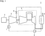
- Fig. 1 is a block diagram schematically illustrating a configuration of a single-shaft combined-cycle power plant according to an embodiment.
- Fig. 2 is a top view of a steam turbine of the single-shaft combined-cycle power plant according to the embodiment.
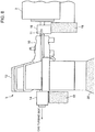
- Fig. 3 is a side view taken from a direction of an arrow A of Fig. 2 .
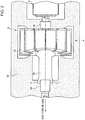
- Fig. 4 is a cross-sectional view taken along a line B-B of Fig.2 .
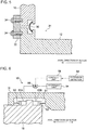
- Fig. 5 is a cross-sectional view of a connection section (a bottom one of the two sections indicated as C in Fig.4 ) between a high/intermediate-pressure chamber and a low-pressure chamber of the steam turbine according to the embodiment.
- a generator 2 As shown in Fig.1 , in the single-shaft combined-cycle power plant 1, a generator 2, a steam turbine 3 and a gas turbine 4 are arranged on the same shaft (a rotor 9) in this order.
- the exhaust gas exhausted from the gas turbine 4 is supplied to an exhaust heat recovery boiler 5.
- feed-water is heated by heat exchange with the exhaust gas from the gas turbine 4, thereby generating steam.
- the steam is then supplied to the steam turbine 3 via a steam-governing valve 6.
- the steam having performed the work in the steam turbine 3 is condensed in a condenser 7 and then recirculated to the exhaust heat recovery boiler 5 by a feed-water pump 8 while the generator 2 is driven by the steam turbine 3 and the gas turbine 4.
- the steam turbine 3 includes a high/intermediate-pressure chamber 10 and a low-pressure chamber 12 as shown in Fig.2 and Fig.3 .
- Fig.4 shows the high/intermediate-pressure chamber 10 housing high-pressure blade rows 22 and intermediate-pressure blade rows 24, and the low-pressure chamber 12 housing low-pressure blade rows 26.
- the high/intermediate-pressure chamber 10 and the low-pressure chamber 12 are connected to each other in a single casing. Further, the configuration of a connection section C (see Fig.4 ) between the high/intermediate-pressure chamber 10 and the low-pressure chamber 12 is described later in reference to Fig.5 .
- a first bearing housing 14 is provided between the gas turbine 4 and the steam turbine 3 and a second bearing housing 16 is provided between the steam turbine 3 and the generator 2.
- the first bearing housing 14 houses a thrust bearing 15 and a radial bearing 17.
- the second bearing housing 16 houses a radial bearing 17.
- the thrust bearing 15 and the radial bearings 17 support the rotor 9 axially at both ends of the casing (the high/intermediate-pressure chamber 10 and the low-pressure chamber 12) of the steam turbine 3.
- the first bearing housing 14 and the second bearing housing 16 are installed on a foundation 18.
- the low-pressure chamber 12 of the steam turbine 3 is fixed by an anchor 20.
- the high/intermediate-pressure chamber 10 has a halved structure separable into an upper chamber 10A and a lower chamber 10B.
- the high/intermediate-pressure chamber 10 is supported by the foundation 18 via a casing support part 11 projecting from the lower chamber 10B (however, the state of the casing support part 11 being supported by the foundation 18 is not illustrated in Fig.3 which shows a cross-section of the foundation 18 taken along a vertical plane passing through a center axis of the rotor.
- the state of the casing support part 11 being supported by the foundation 18 is illustrated in Fig.2 and Fig.6 that is described later.).
- high-pressure steam 40 generated in the exhaust heat recovery boiler 5 enters the high/intermediate-pressure chamber 10 and performs the work in the high-pressure blade rows 22 and exists as high-pressure exhaust steam 41.
- the high-pressure exhaust steam 41 is heated in a reheater (not shown) and then enters the high/intermediate-pressure chamber 10 again as reheat steam 42 and performs the work in the intermediate-pressure blade rows 24.
- low-pressure steam 43 enters the low-pressure chamber 12 and performs the work in the low-pressure blade rows 26 and then is lead to the condenser 7 as the low-pressure exhaust steam 44 via an exhaust hood 46.
- the high/intermediate-pressure chamber 10 is arranged on the side closer to the gas turbine 4, i.e. on the side closer to the thrust bearing 15 from which the rotor 9 thermally extends.
- the thermal extension difference between the high/intermediate-pressure chamber 10 and the rotor 9 is suppressed and thus the clearance between the rotary part (blade rows) and the stationary part (vane rows) in the high/intermediate chamber 10 can be set smaller.
- the high/intermediate-pressure chamber 10 and the low-pressure chamber 12 are separated and are connected by providing an expansion joint 30 therebetween.
- the high/intermediate-pressure chamber 10 and the rotor 9 do not thermally extend in opposite directions although the high/intermediate-pressure chamber 10 is arranged on the side closer to the thrust bearing 15.
- the expansion joint 30 seals an interior space 31 of the casing (the high/intermediate-pressure chamber 10 and the low-pressure chamber 12) of the steam turbine 3.
- the expansion joint 30 is also capable of absorbing thermal extension of the high/intermediate-pressure chamber 10 and/or the low-pressure chamber 12.
- the expansion joint 30 may be constituted of an elastic member or bellows, which can be deformed in response to the thermal extension.
- the high/intermediate-pressure chamber 10 and the low-pressure chamber 12 are rigidly fixed by a connecting block 32 and a fixing bolt 34 and the entire casing can be hoisted by a crane.
- the high/intermediate-pressure chamber 10 and the low-pressure chamber 12 can be separated by removing the fixing bolt 34 or removing the connecting block 32 itself and the thermal extension of the high/intermediate-pressure chamber 10 and/or the low-pressure chamber 12 can be absorbed by the expansion joint 30.
- the high/intermediate-pressure chamber 10 and the low-pressure chamber 12 of the steam turbine 3 are connected by the expansion joint 30, the thrust bearing 15 is provided between the gas turbine 4 and the steam turbine 3, the high/intermediate-pressure chamber 10 is arranged closer to the thrust bearing 15 than the low-pressure chamber 12 in the casing of the steam turbine 3, and the low-pressure chamber 12 is fixed by the anchor 20.
- the high/intermediate-pressure chamber 10 is arranged on the side closer to the thrust bearing 15 from which the rotor 9 thermally extends and thus the thermal extension difference between the high/intermediate-pressure chamber 10 and the rotor 9 can be suppressed.
- the clearance between the rotary part and the stationary part in the high/intermediate-pressure chamber 10 can be reduced and the performance decline of the high-pressure blade rows 22 can be suppressed.
- a steam turbine for the single-shaft combined-cycle power plant according to a second embodiment is described.
- the steam turbine of this embodiment has components in common with the steam turbine 3 of the first embodiment except for a position-adjusting unit for adjusting a position of the high/intermediate-pressure chamber 10 in the axial direction of the rotor. Therefore, components different from the first embodiment are mainly described while the components in common with the first embodiment are not further described.
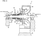
- Fig. 6 is a diagram illustrating the position-adjusting unit for adjusting the position of the high/intermediate-pressure chamber 10 according to this embodiment.
- the position-adjusting unit 50 includes a pair of hydraulic cylinders 52 (52A, 52B) attached to the casing support part 11 of the high/intermediate-pressure chamber 10 (see Fig.2 and Fig.3 ), a hydraulic unit 54 for supplying a hydraulic pressure to the hydraulic cylinders 52, and a switching valve 56 for switching a hydraulic cylinder 52 to be supplied with the hydraulic pressure between the pair of hydraulic cylinders 52.
- the pair of hydraulic cylinders 52 (52A, 52B) is attached to the casing support 11 opposite to each other. More specifically, piston parts 53 of the hydraulic cylinders 52 (52A, 52B) are attached to an inner wall surface of a recessed portion 51 formed in the casing support part 11.
- the switching valve 56 is a three-way valve connected to the hydraulic cylinders 52 (52A, 52B) and the hydraulic unit 54.
- a control unit 58 is provided for controlling the switching valve 56 and a differential expansion indicator 59 is provided for detecting a thermal extension difference between the high/intermediate-pressure chamber 10 and the rotor 9.
- the control unit 58 controls the switching valve 56 based on the thermal extension difference detected by the differential expansion indicator 59, so as to switch a hydraulic cylinder to be supplied with the hydraulic pressure generated in the hydraulic unit 54.
- the control unit 58 controls the switching valve 56 based on the detection result of the differential expansion indicator 59 so as to supply the hydraulic pressure to the hydraulic cylinder 52A and to move the casing support part 11 leftward in Fig.6 .
- the thermal extension difference between the high/intermediate-pressure chamber 10 and the rotor 9 is canceled out, thereby preventing the rotary part and the stationary part from contacting each other in the high/intermediate-pressure chamber 10.
- Fig.7A and Fig.7B are illustrations of the differential expansion indicator 59 according to this embodiment.
- the differential expansion indicator 59 includes a taper surface 59A which is formed on the rotor 9 and whose diameter changes, and a non-contact sensor 59B arranged opposite to the taper surface 59A.
- the taper surface 59A and the non-contact sensor 59B are provided outside the casing of the steam turbine 3.
- the non-contact sensor 59B measures a distance ⁇ X to the taper surface 59A to calculate a thermal extension amount of the rotor from the distance ⁇ X.
- a disk part 59C may be provided on the rotor 9.
- the disk part 59C has a diameter different from the rest of the rotor 9.
- the thermal extension amount of the rotor 9 may be calculated from the distance ⁇ X to the disk part 59C measured by non-contact sensor 59B.
- the thermal extension difference between the rotor 9 and the high/intermediate-pressure chamber 10 is obtained.
- the thermal extension difference between the rotor 9 and the high/intermediate-pressure chamber 10 may be directly obtained from the distance ⁇ X measured by the non-contact sensor 59B (see Fig.7A and Fig.7B ).
- the position-adjusting unit 50 is provided so as to freely adjust the position of the high/intermediate-pressure chamber 10 in the axial direction of the rotor 9.
- the thermal extension difference between the high/intermediate-pressure chamber 10 and the rotor 9 can be canceled out, thereby preventing the rotary part and the stationary part from contacting each other.
- the position of the high/intermediate-pressure chamber 10 can be adjusted by the position-adjusting unit 50 as the low-pressure chamber 12 being the heaviest section is separated from the high/intermediate-pressure chamber 10 (the high/intermediate-pressure chamber 10 and the low-pressure chamber 12 are connected via the expansion joint 30) in the steam turbine 3. More specifically, it is possible to adjust the position of the high/intermediate-pressure chamber 10, which is relatively lightweight, as a single unit by the position-adjusting unit 50 using the hydraulic pressure.
- the high/intermediate-pressure chamber 10 i.e. the casing support part 11
- the switching valve 56 By switching a hydraulic-pressure supply state of the pair of hydraulic cylinders 52 (52A, 52B) using the switching valve 56, the high/intermediate-pressure chamber 10 (i.e. the casing support part 11) can be moved in both directions along the axial direction of the rotor 9.
- the thermal extension difference between the high/intermediate-pressure chamber 10 and the rotor 9 when the temperature is increasing or decreasing, thereby preventing the rotary part and the stationary part from contacting each other.
- the switching valve 56 is controlled by the control unit 58 based on the detection result of the thermal extension difference between the high/intermediate-pressure chamber 10 and the rotor 9, which has been detected by the differential expansion indicator 59.
- the control unit 58 controls the switching valve 56 based on the detection result of the thermal extension difference between the high/intermediate-pressure chamber 10 and the rotor 9, which has been detected by the differential expansion indicator 59.
- a steam turbine for the single-shaft combined-cycle power plant according to a third embodiment is described.
- the steam turbine of this embodiment has components in common with the steam turbine 3 of the first embodiment except for the position-adjusting unit 50 for adjusting the position of the high/intermediate-pressure chamber 10 in the axial direction of the rotor and a reverse arrangement of the high/intermediate-pressure chamber 10 and the low-pressure chamber 12. Further, the position-adjusting unit 50 is already described in the second embodiment. Thus, components different from the first and second embodiments are mainly described while the components in common with the first and second embodiments are not further described.
- Fig. 8 is a side view of the steam turbine of the single-shaft combined-cycle power plant according to this embodiment.
- the low-pressure chamber 12 is arranged on a side closer to the first bearing housing 14 (i.e. on the side closer to the thrust bearing 15 from which the rotor 9 thermally extends (see Fig.4 )).
- the arrangement of the low-pressure chamber 12 on the side closer to the thrust bearing 15 is the same as the conventional single-casing steam turbine.
- the high/intermediate-pressure chamber 10 and the low-pressure chamber 12 are connected to each other by the expansion joint 30 in the same manner as the first embodiment (see Fig.5 ).
- the position-adjusting unit 50 (see Fig.6 ) is provided for adjusting the position of the high/intermediate-pressure chamber 10 in the axial direction of the rotor 9.
- the position-adjusting unit 50 is provided so as to freely adjust the position of the high/intermediate-pressure chamber 10 in the axial direction of the rotor 9.
- the thermal extension difference between the high/intermediate-pressure chamber 10 and the rotor 9 can be canceled out, thereby preventing the rotary part and the stationary part from contacting each other. Therefore, even in the case where the low-pressure chamber 12 fixed by the anchor 20 is arranged on the side closer to the thrust bearing 15, from which the rotor 9 thermally extends, in the manner similar to the conventional steam turbine, it is possible to reduce the clearance between the rotary part and the stationary part in the high/intermediate-pressure chamber 10 and to reliably suppress the performance decline of the high-pressure blade rows 22.
- the position of the high/intermediate-pressure chamber 10 can be adjusted by the position-adjusting unit 50 as the low-pressure chamber 12 being the heaviest section is separated from the high/intermediate-pressure chamber 10 (the high/intermediate-pressure chamber 10 and the low-pressure chamber 12 are connected via the expansion joint 30). More specifically, it is possible to adjust the position of the high/intermediate-pressure chamber 10, which is relatively lightweight, as a single unit by the position-adjusting unit 50 using the hydraulic pressure.
- the steam turbine 3 is integrated in the combined-cycle power plant 1.
- this is not limitative and the present invention is also applicable to a single-casing steam turbine that is used alone.
Landscapes
- Engineering & Computer Science (AREA)
- Chemical & Material Sciences (AREA)
- Combustion & Propulsion (AREA)
- Mechanical Engineering (AREA)
- General Engineering & Computer Science (AREA)
- Engine Equipment That Uses Special Cycles (AREA)
- Turbine Rotor Nozzle Sealing (AREA)
- Control Of Turbines (AREA)
Description
- A present disclosure relates to a single-casing steam turbine and a single-shaft combined-cycle power plant using the single-casing steam turbine that are used in a power generating station or the like.
- As the steam turbine used in the power generating station or the like, a single-casing steam turbine (e.g. single-casing reheat turbine: SRT) is well known, which houses high-pressure blade rows and low-pressure blade rows in a single casing to achieve a shorter axial length and a compact steam turbine.
- It is common in a steam turbine to set a clearance based on a fluctuation amount of the distance between a rotary part and a stationary part that is expected under an operation condition so that the rotary part and the stationary part do not contact with each other, and to arrange the rotary part with an offset with respect to the stationary part. This is due to the fact that temperature change of the steam turbine from a stopped state to a rated operation state causes a thermal extension difference between the rotor and the casing, which results in changing of the space between the rotary part and the stationary part.
- Therefore, in the case of the single-casing steam turbine, a low-pressure chamber being the heaviest is fixed by an anchor and the overall casing (particularly, the high-pressure chamber and the intermediate-pressure chamber) is allowed to thermally extend freely from the anchor so as to prevent thermal deformation. Meanwhile, the rotor thermally extends from a thrust bearing which rotatably supports the rotor.
- Therefore, from a perspective of reducing the thermal extension difference by making the rotor and the casing thermally extend in the same direction, it is necessary to arrange the low-pressure chamber on a side closer to the thrust bearing as the casing thermally extends from the anchor fixed to the low-pressure chamber and the rotor thermally extends from the thrust bearing.
- However, by arranging the low-pressure chamber of the single-casing steam turbine on the side closer to the thrust bearing, the high-pressure chamber is inevitably arranged on a side farther from the thrust bearing. For a corresponding amount, the thermal extension difference between the high-pressure chamber and the rotor increases. Thus, it is necessary to provide a large clearance between the rotary part and the stationary part in the high-pressure chamber. However, the large clearance between the rotary part and the stationary part in the high-pressure chamber leads to a decrease in performance of high-pressure blade rows. A blade skeleton of the high-pressure blade rows housed in the high-pressure chamber is particularly small and thus the increased clearance between the rotary part and the stationary part in the high-pressure chamber leads to major decline in the performance of the high-pressure blade rows.
- Therefore, for the purpose of reducing the clearance between the rotary part and the stationary part in the high-pressure chamber of the single-casing steam turbine, it is desired to develop a technique for suppressing the thermal extension difference between the high-pressure chamber and the rotor.
- In recent years, a combined-cycle power plant with a combination of a steam turbine and a gas turbine is in the spotlight as a power plant used for a thermal power station and the like. The combined-cycle power plant includes a single-shaft power plant in which the steam turbine and the gas turbine are coupled on the same shaft to drive a common generator. In particular, a single-shaft combined-cycle power plant using a single-casing steam turbine has become one of today's mainstream power plants with increasing length of end blades in recent years.
- In the single-shaft combined-cycle power plant using the single-casing steam turbine, the thrust bearing is arranged between the steam turbine and the gas turbine and the rotor thermally extends from the thrust bearing. Thus, from a perspective of making the rotor and the casing thermally extend in the same direction, the low-pressure chamber fixed by the anchor from which the casing thermally extends, is arranged on the side closer to the thrust bearing from which the rotor thermally extends, i.e. toward the gas turbine. Therefore, in the single-shaft combined-cycle power plant using the single-casing steam turbine, it is inevitable to secure a large clearance between the rotary part and the stationary part in the high-pressure chamber with respect to the blade skeleton of the high-pressure blade rows in correspondence to the large thermal extension difference between the rotor and the high-pressure chamber arranged on the side farther from the thrust bearing. This generates an issue of the performance decline of the high-pressure blade rows.
- Particularly, the combined-cycle power plant is normally arranged in a large-scale thermal power station and the steam turbine is axially large in length. Therefore, in the combined-cycle power plant using the single-casing steam turbine, it is necessary to set the clearance considerably large between the rotary part and the stationary part in the high-pressure chamber and thus the issue of the performance decline of the high-pressure blade rows tends to occur.
- In this regard,
JP 59-18207 A -
DE 3941089 A1 discloses an air sealing for opposing flanges, wherein a groove forms a gas channel, to avoid undesired gas-leakage between the flanges. - Further,
JP H04 132 805 A - Further,
JP S59 18207 A - Moreover,
JP H10 169408 - The space-adjusting unit described in
JP 59-18207 A JP 59-18207 A - Therefore, it is difficult to suppress the performance decline of the high-pressure blade rows by adjusting the space between the high-pressure chamber and the rotor by means of the space-adjusting unit disclosed in
JP 59-18207 A - In view of the above issues, it is an object of at least one embodiment of the present invention to provide a single-casing steam turbine and a single-shaft combined-cycle power plant, that are capable of suppressing the performance decline of the high-pressure blade rows.
- A single-casing steam turbine according to at least one embodiment of the present invention, comprises:
- blade rows including at least high-pressure blade rows and low-pressure blade rows;
- a high-pressure chamber housing the high-pressure blade rows;
- a low-pressure chamber housing the low-pressure blade rows; and
- an expansion joint connecting the high-pressure chamber and the low-pressure chamber to each other and sealing an interior space of the high-pressure chamber and the low-pressure chamber.
- In the present description, "single-casing steam turbine" indicates a steam turbine having blade rows including at least high-pressure blade rows and low-pressure blade rows that are housed in a single casing, and "high-pressure chamber" indicates a part where blade rows excluding the low-pressure blade rows are housed. For instance, the single-casing steam turbine may include intermediate-pressure blade rows in addition to the high-pressure blade rows and the low-pressure blade rows. In this case, the high-pressure chamber houses the high-pressure blade rows and the intermediate-pressure blade rows.
- Further, "expansion joint" indicates a joint that is capable of sealing an interior space of the casing and absorbing the thermal extension of the high/intermediate-pressure chamber and/or the low-pressure chamber. For instance, the expansion joint may be constituted of an elastic member or bellows, which can be deformed in response to the thermal extension.
- According to the above single-casing steam turbine, by connecting the high-pressure chamber and the low-pressure chamber by the expansion joint, the high-pressure chamber can be arranged on the side closer to the thrust bearing from which the rotor thermally extends. More specifically, the high-pressure chamber is separated from the low-pressure chamber fixed by the anchor and thus the high-pressure chamber thermally expands independently. Thus, the high-pressure chamber can be arranged on the side closer to the thrust bearing without causing the casing and the rotor to thermally extend in opposite directions. As a result, with the high-pressure chamber being arranged on the side closer to the thrust bearing, the thermal extension difference between the high-pressure chamber and the rotor is suppressed and thus it is possible to reduce the clearance between the rotary part and the stationary part in the high-pressure chamber and to suppress the performance decline of the high-pressure blade rows.
- In some embodiments, the single-casing steam turbine further comprises a position-adjusting unit for adjusting a position of the high-pressure chamber in an axial direction of a rotor.
- By adjusting the position of the high-pressure chamber by means of the position-adjusting unit, even when the clearance between the rotary part and the stationary part is comparatively small in the high-pressure chamber, the thermal extension difference between the high-pressure chamber and the rotor can be canceled out. Therefore, the rotary part and the stationary part are prevented from contacting each other. As a result, it is possible to further reduce the clearance between the rotary part and the stationary part in the high-pressure chamber and to reliably suppress the performance decline of the high-pressure blade rows.
- Further, the thermal extension difference between the high-pressure chamber and the rotor can be offset and the rotary part and the stationary part are prevented from contacting each other. Therefore, even in the case where the low-pressure chamber fixed by the anchor is arranged on the side closer to the thrust bearing, from which the rotor thermally extends, in the manner similar to the conventional case, it is possible to reduce the clearance between the rotary part and the stationary part in the high-pressure chamber and to reliably suppress the performance decline of the high-pressure blade rows.
- Furthermore, the position of the high-pressure chamber can be adjusted by the position-adjusting unit as the low-pressure chamber being the heaviest section is separated from the high-pressure chamber in the above single-casing steam turbine. More specifically, it is possible to easily adjust the position of the high-pressure chamber, which is relatively lightweight, as a single unit using a position-adjusting unit constituted by known actuators such as hydraulic jacks.
- In some embodiments, the position-adjusting unit comprises:
- a pair of hydraulic cylinders for moving a casing support part of the high-pressure chamber in opposite directions along the axial direction of the rotor, the pair of hydraulic cylinders being attached to the casing support part of the high-pressure chamber;
- a hydraulic unit for supplying a hydraulic pressure to the pair of hydraulic cylinders; and
- a switching valve for switching a hydraulic cylinder to be supplied with the hydraulic pressure between the pair of hydraulic cylinders, the switching valve being provided between the pair of hydraulic cylinders and the hydraulic unit.
- The hydraulic cylinder to be used is switched by the switching valve so as to move the high-pressure chamber backward and forward along the axial direction of the rotor. As a result, it is possible to cancel out the thermal extension difference between the high-pressure chamber and the rotor in accordance with the operation state of the steam turbine (such as when the temperature is increasing or decreasing), thereby preventing the rotary part and the stationary part from contacting each other.
- In some embodiments, the above single-casing steam turbine further comprises:
- a detection unit for detecting a thermal extension difference between the rotor and the high-pressure chamber; and
- a control unit for controlling the position-adjusting unit based on the thermal extension difference detected by the detection unit.
- As a result, it is possible to reliably prevent the rotary part and the stationary part from contacting each other by adjusting the position of the high-pressure chamber so as to cancel out the thermal extension difference between the rotor and the high-pressure chamber.
- In some embodiments, the rotor may include, in the outside of a casing of the steam turbine, a disk part where the rotor has a shaft diameter different from the rest of the rotor or a taper surface where the rotor changes in diameter,, and the detection unit may include a sensor for measuring a distance to an end surface of the disk part or the taper surface of the rotor.
- A single-shaft combined cycle power plant according to at least one embodiment of the present invention, comprises a generator, the single-casing steam turbine described above, a gas turbine that are coupled in this order. In the single-shaft combined cycle power plant, a thrust bearing is provided between the gas turbine and the steam turbine, the high-pressure chamber is arranged closer to the thrust bearing than the low-pressure chamber in a casing of the steam turbine, and the low-pressure chamber is fixed by an anchor.
- According to this single-shaft combined cycle power plant, the high-pressure chamber is arranged on the side closer to the thrust bearing from which the rotor thermally extends and thus the thermal extension difference between the high-pressure chamber and the rotor can be suppressed. Therefore, it is possible to suppress the performance decline of the high-pressure blade rows by reducing the clearance between the rotary part and the stationary part in the high-pressure chamber.
- The high-pressure chamber can be arranged on the side closer to the thrust bearing in the above manner, as the low-pressure chamber fixed by the anchor and the high-pressure chamber are separated and the arrangement of the high-pressure chamber on the side closer to the thrust bearing does not cause the casing and the rotor to thermally extend in opposite directions.
- In some embodiments, a position-adjusting unit is provided for adjusting a position of the high-pressure chamber in the axial direction of the rotor.
- By adjusting the position of the high-pressure chamber by means of the position-adjusting unit, even when the clearance between the rotary part and the stationary part is comparatively small in the high-pressure chamber, the thermal extension difference between the high-pressure chamber and the rotor can be canceled out. Therefore, the rotary part and the stationary part are prevented from contacting each other. As a result, it is possible to further reduce the clearance between the rotary part and the stationary part in the high-pressure chamber and to reliably suppress the performance decline of the high-pressure blade rows.
- Alternatively, in some embodiments, a single-shaft combined cycle power plant comprises a generator, the single-casing steam turbine described above, and a gas turbine that are coupled in this order. In this single-shaft combined cycle power plant, a thrust bearing is provided between the gas turbine and the steam turbine, the low-pressure chamber is arranged closer to the thrust bearing than the high-pressure chamber in a casing of the steam turbine, the combined cycle power plant may further comprises a position-adjusting unit for adjusting a position of the high-pressure chamber in an axial direction of a rotor, and the low-pressure chamber is fixed by an anchor.
- By providing the position-adjusting unit, the thermal extension difference between the high-pressure chamber and the rotor is canceled out so as to prevent the rotary part and the stationary part from contacting each other. Therefore, even in the case where the low-pressure chamber fixed by the anchor is arranged on the side closer to the thrust bearing from which the rotor thermally extends, it is still possible to reduce the clearance between the rotary part and the stationary part in the high-pressure chamber and to reliably suppress the performance decline of the high-pressure blade rows.
- According to at least one embodiment of the present invention, by connecting the high-pressure chamber and the low-pressure chamber by the expansion joint, the high-pressure chamber can be arranged on the side closer to the thrust bearing from which the rotor thermally extends. More specifically, the high-pressure chamber is separated from the low-pressure chamber fixed by the anchor and thus the high-pressure chamber thermally expands independently. Thus, the high-pressure chamber can be arranged on the side closer to the thrust bearing without causing the casing and the rotor to thermally extend in opposite directions. As a result, with the high-pressure chamber being arranged on the side closer to the thrust bearing, the thermal extension difference between the high-pressure chamber and the rotor is suppressed and thus it is possible to reduce the clearance between the rotary part and the stationary part in the high-pressure chamber and to suppress the performance decline of the high-pressure blade rows.
- Further, in the case of providing the position-adjusting unit for adjusting the position of the high-pressure chamber in the axial direction of the rotor according to some embodiments, the thermal extension difference between the high-pressure chamber and the rotor can be offset and the rotary part and the stationary part are prevented from contacting each other. Therefore, even in the case where the low-pressure chamber fixed by the anchor is arranged on the side closer to the thrust bearing, from which the rotor thermally extends, in the manner similar to the conventional case, it is possible to reduce the clearance between the rotary part and the stationary part in the high-pressure chamber and to reliably suppress the performance decline of the high-pressure blade rows.
-
- [
Fig. 1] Fig. 1 is a block diagram schematically illustrating a configuration of a single-shaft combined-cycle power plant according to an embodiment. - [
Fig. 2] Fig. 2 is a top view of a steam turbine of the single-shaft combined-cycle power plant according to the embodiment. - [
Fig. 3] Fig. 3 is a side view taken from a direction of an arrow A ofFig.2 . - [
Fig. 4] Fig. 4 is a cross-sectional view taken along a line B-B ofFig.2 . - [
Fig. 5] Fig. 5 is a cross-sectional view of a connection section between a high/intermediate-pressure chamber and a low-pressure chamber of the steam turbine according to the embodiment. - [
Fig. 6] Fig. 6 is a diagram illustrating a position-adjusting unit for adjusting a position of the high/intermediate-pressure chamber according to another embodiment. - [
Fig. 7A] Fig. 7A is an illustration of a differential expansion indicator according to an embodiment. - [
Fig. 7B] Fig. 7B is an illustration of a differential expansion indicator according to another embodiment. - [
Fig. 8] Fig. 8 is a side view of the steam turbine of the single-shaft combined-cycle power plant according to yet another embodiment. - Embodiments of the present invention will now be described in detail with reference to the accompanying drawings. It is intended, however, that unless particularly specified in these embodiments, dimensions, materials, shape, its relative positions and the like shall be interpreted as illustrative only and not limitative of the scope of the present invention.
- A steam turbine for a single-shaft combined-cycle power plant according to a first embodiment is now described.
-
Fig. 1 is a block diagram schematically illustrating a configuration of a single-shaft combined-cycle power plant according to an embodiment.Fig. 2 is a top view of a steam turbine of the single-shaft combined-cycle power plant according to the embodiment.Fig. 3 is a side view taken from a direction of an arrow A ofFig. 2 .Fig. 4 is a cross-sectional view taken along a line B-B ofFig.2 .Fig. 5 is a cross-sectional view of a connection section (a bottom one of the two sections indicated as C inFig.4 ) between a high/intermediate-pressure chamber and a low-pressure chamber of the steam turbine according to the embodiment. - As shown in
Fig.1 , in the single-shaft combined-cycle power plant 1, agenerator 2, asteam turbine 3 and agas turbine 4 are arranged on the same shaft (a rotor 9) in this order. - The exhaust gas exhausted from the
gas turbine 4 is supplied to an exhaustheat recovery boiler 5. In the exhaustheat recovery boiler 5, feed-water is heated by heat exchange with the exhaust gas from thegas turbine 4, thereby generating steam. The steam is then supplied to thesteam turbine 3 via a steam-governing valve 6. Then, the steam having performed the work in thesteam turbine 3 is condensed in acondenser 7 and then recirculated to the exhaustheat recovery boiler 5 by a feed-water pump 8 while thegenerator 2 is driven by thesteam turbine 3 and thegas turbine 4. - The
steam turbine 3 includes a high/intermediate-pressure chamber 10 and a low-pressure chamber 12 as shown inFig.2 andFig.3 .Fig.4 shows the high/intermediate-pressure chamber 10 housing high-pressure blade rows 22 and intermediate-pressure blade rows 24, and the low-pressure chamber 12 housing low-pressure blade rows 26. In thesteam turbine 3, the high/intermediate-pressure chamber 10 and the low-pressure chamber 12 are connected to each other in a single casing. Further, the configuration of a connection section C (seeFig.4 ) between the high/intermediate-pressure chamber 10 and the low-pressure chamber 12 is described later in reference toFig.5 . - As shown in
Fig.2 to Fig.4 , a first bearinghousing 14 is provided between thegas turbine 4 and thesteam turbine 3 and asecond bearing housing 16 is provided between thesteam turbine 3 and thegenerator 2. Thefirst bearing housing 14 houses athrust bearing 15 and aradial bearing 17. The second bearing housing 16 houses aradial bearing 17. Thethrust bearing 15 and theradial bearings 17 support therotor 9 axially at both ends of the casing (the high/intermediate-pressure chamber 10 and the low-pressure chamber 12) of thesteam turbine 3. Thefirst bearing housing 14 and the second bearinghousing 16 are installed on afoundation 18. - As shown in
Fig.3 , the low-pressure chamber 12 of thesteam turbine 3 is fixed by ananchor 20. In contrast, the high/intermediate-pressure chamber 10 has a halved structure separable into anupper chamber 10A and alower chamber 10B. The high/intermediate-pressure chamber 10 is supported by thefoundation 18 via acasing support part 11 projecting from thelower chamber 10B (however, the state of thecasing support part 11 being supported by thefoundation 18 is not illustrated inFig.3 which shows a cross-section of thefoundation 18 taken along a vertical plane passing through a center axis of the rotor. The state of thecasing support part 11 being supported by thefoundation 18 is illustrated inFig.2 andFig.6 that is described later.). - As shown in
Fig.4 , high-pressure steam 40 generated in the exhaust heat recovery boiler 5 (seeFig.1 ) enters the high/intermediate-pressure chamber 10 and performs the work in the high-pressure blade rows 22 and exists as high-pressure exhaust steam 41. The high-pressure exhaust steam 41 is heated in a reheater (not shown) and then enters the high/intermediate-pressure chamber 10 again asreheat steam 42 and performs the work in the intermediate-pressure blade rows 24. In contrast, low-pressure steam 43 enters the low-pressure chamber 12 and performs the work in the low-pressure blade rows 26 and then is lead to thecondenser 7 as the low-pressure exhaust steam 44 via anexhaust hood 46. - In the combined-cycle power plant 1 having the above structure, in this embodiment, the high/intermediate-
pressure chamber 10 is arranged on the side closer to thegas turbine 4, i.e. on the side closer to the thrust bearing 15 from which therotor 9 thermally extends. As a result, the thermal extension difference between the high/intermediate-pressure chamber 10 and therotor 9 is suppressed and thus the clearance between the rotary part (blade rows) and the stationary part (vane rows) in the high/intermediate chamber 10 can be set smaller. Thus, it is possible to suppress the performance decline of the high-pressure blade rows 22. - To achieve the above arrangement of the high/intermediate-
pressure chamber 10 on the side closer to thethrust bearing 15, the high/intermediate-pressure chamber 10 and the low-pressure chamber 12 are separated and are connected by providing anexpansion joint 30 therebetween. By separating the high/intermediate-pressure chamber 10 from the low-pressure chamber 12 fixed by theanchor 20, the high/intermediate-pressure chamber 10 and therotor 9 do not thermally extend in opposite directions although the high/intermediate-pressure chamber 10 is arranged on the side closer to thethrust bearing 15. As a result, it is possible to achieve the above arrangement of the high/intermediate-pressure chamber 10 on the side closer to thethrust bearing 15. - The expansion joint 30 seals an
interior space 31 of the casing (the high/intermediate-pressure chamber 10 and the low-pressure chamber 12) of thesteam turbine 3. Theexpansion joint 30 is also capable of absorbing thermal extension of the high/intermediate-pressure chamber 10 and/or the low-pressure chamber 12. For instance, theexpansion joint 30 may be constituted of an elastic member or bellows, which can be deformed in response to the thermal extension. - When disassembling the
steam turbine 3 for periodical inspection, the high/intermediate-pressure chamber 10 and the low-pressure chamber 12 are rigidly fixed by a connectingblock 32 and a fixingbolt 34 and the entire casing can be hoisted by a crane. In contrast, when operating thesteam turbine 3, the high/intermediate-pressure chamber 10 and the low-pressure chamber 12 can be separated by removing the fixingbolt 34 or removing the connectingblock 32 itself and the thermal extension of the high/intermediate-pressure chamber 10 and/or the low-pressure chamber 12 can be absorbed by theexpansion joint 30. - As described above, in the single-shaft combined-cycle power plant 1 according to the first embodiment in which the
generator 2, the single-casing steam turbine 3 and thegas turbine 4 are connected in this order, the high/intermediate-pressure chamber 10 and the low-pressure chamber 12 of thesteam turbine 3 are connected by theexpansion joint 30, thethrust bearing 15 is provided between thegas turbine 4 and thesteam turbine 3, the high/intermediate-pressure chamber 10 is arranged closer to the thrust bearing 15 than the low-pressure chamber 12 in the casing of thesteam turbine 3, and the low-pressure chamber 12 is fixed by theanchor 20. - According to the first embodiment, the high/intermediate-
pressure chamber 10 is arranged on the side closer to the thrust bearing 15 from which therotor 9 thermally extends and thus the thermal extension difference between the high/intermediate-pressure chamber 10 and therotor 9 can be suppressed. As a result, the clearance between the rotary part and the stationary part in the high/intermediate-pressure chamber 10 can be reduced and the performance decline of the high-pressure blade rows 22 can be suppressed. - A steam turbine for the single-shaft combined-cycle power plant according to a second embodiment is described. The steam turbine of this embodiment has components in common with the
steam turbine 3 of the first embodiment except for a position-adjusting unit for adjusting a position of the high/intermediate-pressure chamber 10 in the axial direction of the rotor. Therefore, components different from the first embodiment are mainly described while the components in common with the first embodiment are not further described. -
Fig. 6 is a diagram illustrating the position-adjusting unit for adjusting the position of the high/intermediate-pressure chamber 10 according to this embodiment. As shown inFig.6 , the position-adjustingunit 50 includes a pair of hydraulic cylinders 52 (52A, 52B) attached to thecasing support part 11 of the high/intermediate-pressure chamber 10 (seeFig.2 andFig.3 ), ahydraulic unit 54 for supplying a hydraulic pressure to the hydraulic cylinders 52, and a switchingvalve 56 for switching a hydraulic cylinder 52 to be supplied with the hydraulic pressure between the pair of hydraulic cylinders 52. - The pair of hydraulic cylinders 52 (52A, 52B) is attached to the
casing support 11 opposite to each other. More specifically,piston parts 53 of the hydraulic cylinders 52 (52A, 52B) are attached to an inner wall surface of a recessedportion 51 formed in thecasing support part 11. - When the hydraulic pressure is supplied to the
hydraulic cylinder 52A, thecasing support part 11 moves leftward inFig.6 along the axial direction of the rotor. In contrast, when the hydraulic pressure is supplied to thehydraulic cylinder 52B, thecasing support part 11 moves rightward inFig.6 along the axial direction of the rotor. Thehydraulic piston 53 is supported by thefoundation 18 so as not to move upon receiving reaction force from thecasing support part 11. Further, a relief valve (not shown) is provided so that, when one of the hydraulic cylinders 52 is supplied with the hydraulic pressure, a pressure inside the other of the hydraulic cylinders 52 does not get excessively high. - As the
hydraulic unit 54, a hydraulic pump is used, for instance. The switchingvalve 56 is a three-way valve connected to the hydraulic cylinders 52 (52A, 52B) and thehydraulic unit 54. - Further, a
control unit 58 is provided for controlling the switchingvalve 56 and adifferential expansion indicator 59 is provided for detecting a thermal extension difference between the high/intermediate-pressure chamber 10 and therotor 9. Thecontrol unit 58 controls the switchingvalve 56 based on the thermal extension difference detected by thedifferential expansion indicator 59, so as to switch a hydraulic cylinder to be supplied with the hydraulic pressure generated in thehydraulic unit 54. - For instance, in such a case that the high/intermediate-
pressure chamber 10 extends rightward inFig.6 with respect to therotor 9, thecontrol unit 58 controls the switchingvalve 56 based on the detection result of thedifferential expansion indicator 59 so as to supply the hydraulic pressure to thehydraulic cylinder 52A and to move thecasing support part 11 leftward inFig.6 . As a result, the thermal extension difference between the high/intermediate-pressure chamber 10 and therotor 9 is canceled out, thereby preventing the rotary part and the stationary part from contacting each other in the high/intermediate-pressure chamber 10. -
Fig.7A andFig.7B are illustrations of thedifferential expansion indicator 59 according to this embodiment. As shown inFig.7A , thedifferential expansion indicator 59 includes ataper surface 59A which is formed on therotor 9 and whose diameter changes, and anon-contact sensor 59B arranged opposite to thetaper surface 59A. Thetaper surface 59A and thenon-contact sensor 59B are provided outside the casing of thesteam turbine 3. Thenon-contact sensor 59B measures a distance ΔX to thetaper surface 59A to calculate a thermal extension amount of the rotor from the distance ΔX. Alternatively, as shown inFig.7B , a disk part 59C may be provided on therotor 9. The disk part 59C has a diameter different from the rest of therotor 9. The thermal extension amount of therotor 9 may be calculated from the distance ΔX to the disk part 59C measured bynon-contact sensor 59B. - By calculating a difference between the calculated thermal extension amount of the
rotor 9 and a thermal extension amount of the casing of thesteam turbine 3, which is separately measured, the thermal extension difference between therotor 9 and the high/intermediate-pressure chamber 10 is obtained. Alternatively, in such a case that thenon-contact sensor 59B is directly or indirectly fixed to the casing of the steam turbine 3 (e.g. in such a case that thenon-contact sensor 59B is fixed to the bearing housing integrally formed with the casing), the thermal extension difference between therotor 9 and the high/intermediate-pressure chamber 10 may be directly obtained from the distance ΔX measured by thenon-contact sensor 59B (seeFig.7A andFig.7B ). - According to the second embodiment, the position-adjusting
unit 50 is provided so as to freely adjust the position of the high/intermediate-pressure chamber 10 in the axial direction of therotor 9. Thus, even if the clearance between the rotary part and the stationary part is comparatively small in the high/intermediate-pressure chamber 10, the thermal extension difference between the high/intermediate-pressure chamber 10 and therotor 9 can be canceled out, thereby preventing the rotary part and the stationary part from contacting each other. As a result, it is possible to further reduce the clearance between the rotary part and the stationary part in the high/intermediate-pressure chamber 10 and to reliably suppress the performance decline of the high-pressure blade rows 22. - The position of the high/intermediate-
pressure chamber 10 can be adjusted by the position-adjustingunit 50 as the low-pressure chamber 12 being the heaviest section is separated from the high/intermediate-pressure chamber 10 (the high/intermediate-pressure chamber 10 and the low-pressure chamber 12 are connected via the expansion joint 30) in thesteam turbine 3. More specifically, it is possible to adjust the position of the high/intermediate-pressure chamber 10, which is relatively lightweight, as a single unit by the position-adjustingunit 50 using the hydraulic pressure. - Further, by switching a hydraulic-pressure supply state of the pair of hydraulic cylinders 52 (52A, 52B) using the switching
valve 56, the high/intermediate-pressure chamber 10 (i.e. the casing support part 11) can be moved in both directions along the axial direction of therotor 9. As a result, it is possible to offset the thermal extension difference between the high/intermediate-pressure chamber 10 and therotor 9 when the temperature is increasing or decreasing, thereby preventing the rotary part and the stationary part from contacting each other. - Particularly, the switching
valve 56 is controlled by thecontrol unit 58 based on the detection result of the thermal extension difference between the high/intermediate-pressure chamber 10 and therotor 9, which has been detected by thedifferential expansion indicator 59. As a result, it is possible to reliably prevent the rotary part and the stationary part from contacting each other by positively canceling out the thermal extension difference between the high/intermediate-pressure chamber 10 and therotor 9. - A steam turbine for the single-shaft combined-cycle power plant according to a third embodiment is described. The steam turbine of this embodiment has components in common with the
steam turbine 3 of the first embodiment except for the position-adjustingunit 50 for adjusting the position of the high/intermediate-pressure chamber 10 in the axial direction of the rotor and a reverse arrangement of the high/intermediate-pressure chamber 10 and the low-pressure chamber 12. Further, the position-adjustingunit 50 is already described in the second embodiment. Thus, components different from the first and second embodiments are mainly described while the components in common with the first and second embodiments are not further described. -
Fig. 8 is a side view of the steam turbine of the single-shaft combined-cycle power plant according to this embodiment. In the steam turbine 60 shown inFig.8 , the low-pressure chamber 12 is arranged on a side closer to the first bearing housing 14 (i.e. on the side closer to the thrust bearing 15 from which therotor 9 thermally extends (seeFig.4 )). - The arrangement of the low-
pressure chamber 12 on the side closer to thethrust bearing 15 is the same as the conventional single-casing steam turbine. However, the high/intermediate-pressure chamber 10 and the low-pressure chamber 12 are connected to each other by theexpansion joint 30 in the same manner as the first embodiment (seeFig.5 ). Further, in the same manner as the second embodiment, the position-adjusting unit 50 (seeFig.6 ) is provided for adjusting the position of the high/intermediate-pressure chamber 10 in the axial direction of therotor 9. - According to the third embodiment, the position-adjusting
unit 50 is provided so as to freely adjust the position of the high/intermediate-pressure chamber 10 in the axial direction of therotor 9. Thus the thermal extension difference between the high/intermediate-pressure chamber 10 and therotor 9 can be canceled out, thereby preventing the rotary part and the stationary part from contacting each other. Therefore, even in the case where the low-pressure chamber 12 fixed by theanchor 20 is arranged on the side closer to thethrust bearing 15, from which therotor 9 thermally extends, in the manner similar to the conventional steam turbine, it is possible to reduce the clearance between the rotary part and the stationary part in the high/intermediate-pressure chamber 10 and to reliably suppress the performance decline of the high-pressure blade rows 22. - The position of the high/intermediate-
pressure chamber 10 can be adjusted by the position-adjustingunit 50 as the low-pressure chamber 12 being the heaviest section is separated from the high/intermediate-pressure chamber 10 (the high/intermediate-pressure chamber 10 and the low-pressure chamber 12 are connected via the expansion joint 30). More specifically, it is possible to adjust the position of the high/intermediate-pressure chamber 10, which is relatively lightweight, as a single unit by the position-adjustingunit 50 using the hydraulic pressure. - While the embodiments of the present invention have been described, it is obvious to those skilled in the art that various changes may be made without departing from the scope of the invention.
- For instance, in the above embodiments, the
steam turbine 3 is integrated in the combined-cycle power plant 1. However, this is not limitative and the present invention is also applicable to a single-casing steam turbine that is used alone. -
- 1
- COMBINED-CYCLE POWER PLANT
- 2
- GENERATOR
- 3
- STEAM TURBINE
- 4
- GAS TURBINE
- 5
- EXHAUST HEAT RECOVERY BOILER
- 6
- STEAM GOVERNING VALVE
- 7
- CONDENSER
- 8
- FEED-WATER PUMP
- 9
- ROTOR
- 10
- HIGH/INTERMEDIATE-PRESSURE CHAMBER
- 10A
- UPPER CHAMBER
- 10B
- LOWER CHAMBER
- 11
- CASING SUPPORT PART
- 12
- LOW-PRESSURE CHAMBER
- 14
- FIRST BEARING HOUSING
- 15
- THURST BEARING
- 16
- SECOND BEARING HOUSING
- 17
- RADIAL BEARING
- 18
- FOUNDATION
- 20
- ANCHOR
- 30
- EXPANSION JOINT
- 31
- INTERIOR SPACE
- 32
- CONNECTING BLOCK
- 34
- FIXING BOLT
- 40
- HIGH-PRESSURE STEAM
- 41
- HIGH-PRESSURE EXHAUST STEAM
- 42
- REHEAT STEAM
- 43
- LOW-PRESSURE STEAM
- 44
- LOW-PRESSURE EXHAUST STEAM
- 46
- EXHAUST HOOD
- 50
- POSITION-ADJUSTING UNIT
- 52A
- HYDRAULIC CYLINDER
- 52B
- HYDRAULIC CYLINDER
- 53
- PISTON PART
- 54
- HYDRAULIC UNIT
- 56
- SWITCHING VALVE
- 58
- CONTROL UNIT
- 59
- DIFFERENTIAL EXPANSION INDICATOR
- 59A
- TAPER SURFACE
- 59B
- NON-CONTACT SENSOR
Claims (6)
- A single-casing steam turbine (3) comprising:blade rows including at least high-pressure blade rows (22) and low-pressure blade rows (26);a high-pressure chamber (10) housing the high-pressure blade rows (22);a low-pressure chamber (12) housing the low-pressure blade rows (26);an expansion joint (30) connecting the high-pressure chamber (10) and the low-pressure chamber (12) to each other and sealing an interior space (31) of the high-pressure chamber (10) and the low-pressure chamber (12); anda position-adjusting unit (50) for adjusting a position of the high-pressure chamber (10) in an axial direction of a rotor (9).
- The single-casing steam turbine according to claim 1,
wherein the position-adjusting unit (50) comprises:a pair of hydraulic cylinders (52) for moving a casing support part (11) of the high-pressure chamber (10) in opposite directions along the axial direction of the rotor (9), the pair of hydraulic cylinders (52) being attached to the casing support part (11) of the high-pressure chamber (10);a hydraulic unit (54) for supplying a hydraulic pressure to the pair of hydraulic cylinders (52); anda switching valve (56) for switching a hydraulic cylinder (52) to be supplied with the hydraulic pressure between the pair of hydraulic cylinders (52), the switching valve (56) being provided between the pair of hydraulic cylinders (52) and the hydraulic unit (54). - The single-casing steam turbine according to claim 1 or 2, further comprising:a detection unit (59) for detecting a thermal extension difference between the rotor (9) and the high-pressure chamber (10); anda control unit (58) for controlling the position-adjusting unit based on the thermal extension difference detected by the detection unit (59).
- The single-casing steam turbine according to claim 3,
wherein the rotor (9) has a taper surface (59A) outside a casing of the steam turbine, the rotor (9) changing in diameter along the taper surface (59A), and
wherein the detection unit (59) includes a sensor (59B) for measuring a distance to the taper surface (59A) of the rotor (9). - A single-shaft combined cycle power plant comprising a generator (2), the single-casing steam turbine (3) of claim 1, and a gas turbine (4) that are coupled in this order,
wherein a thrust bearing (15) is provided between the gas turbine (4) and the steam turbine (3),
wherein the high-pressure chamber (10) is arranged closer to the thrust bearing (15) than the low-pressure chamber (12) in a casing of the steam turbine (3), and
wherein the low-pressure chamber (12) is fixed by an anchor (20). - A single-shaft combined cycle power plant comprising a generator (2), the single-casing steam turbine (3) of claim 1, and a gas turbine (4) that are coupled in this order,
wherein a thrust bearing (15) is provided between the gas turbine (4) and the steam turbine (3),
wherein the low-pressure chamber (12) is arranged closer to the thrust bearing (15) than the high-pressure chamber (10) in a casing of the steam turbine (3),
wherein the combined cycle power plant further comprises the position-adjusting unit (50) for adjusting a position of the high-pressure chamber (10) in an axial direction of a rotor (9), and
wherein the low-pressure chamber (12) is fixed by an anchor (20).
Applications Claiming Priority (2)
| Application Number | Priority Date | Filing Date | Title |
|---|---|---|---|
| JP2012033262A JP5999919B2 (en) | 2012-02-17 | 2012-02-17 | Single-chamber steam turbine and single-shaft combined cycle power generator |
| PCT/JP2012/068917 WO2013121603A1 (en) | 2012-02-17 | 2012-07-26 | Single-casing steam turbine and single-shaft combined-cycle power generation apparatus |
Publications (3)
| Publication Number | Publication Date |
|---|---|
| EP2816201A1 EP2816201A1 (en) | 2014-12-24 |
| EP2816201A4 EP2816201A4 (en) | 2015-12-02 |
| EP2816201B1 true EP2816201B1 (en) | 2017-02-01 |
Family
ID=48982382
Family Applications (1)
| Application Number | Title | Priority Date | Filing Date |
|---|---|---|---|
| EP12868914.8A Active EP2816201B1 (en) | 2012-02-17 | 2012-07-26 | Single-casing steam turbine and single-shaft combined-cycle power generation apparatus |
Country Status (7)
| Country | Link |
|---|---|
| US (1) | US9334757B2 (en) |
| EP (1) | EP2816201B1 (en) |
| JP (1) | JP5999919B2 (en) |
| KR (1) | KR101644254B1 (en) |
| CN (1) | CN104105847B (en) |
| IN (1) | IN2014MN01437A (en) |
| WO (1) | WO2013121603A1 (en) |
Families Citing this family (16)
| Publication number | Priority date | Publication date | Assignee | Title |
|---|---|---|---|---|
| JP2015119520A (en) * | 2013-12-17 | 2015-06-25 | 三菱電機株式会社 | Power-generating plant |
| WO2015125239A1 (en) * | 2014-02-19 | 2015-08-27 | 三菱重工コンプレッサ株式会社 | Rotation system |
| JP2016070225A (en) * | 2014-09-30 | 2016-05-09 | 富士電機株式会社 | Steam turbine facility |
| DE102014224419A1 (en) * | 2014-11-28 | 2016-06-02 | Siemens Aktiengesellschaft | Turbine housing arrangement, in particular with an outer housing part and a Abdampfgehäusenteil a steam turbine, and use thereof |
| WO2017169483A1 (en) * | 2016-03-31 | 2017-10-05 | 三菱日立パワーシステムズ株式会社 | Casing position adjustment device |
| JP7093238B2 (en) * | 2018-06-18 | 2022-06-29 | 三菱重工業株式会社 | Steam turbine equipment and combined cycle plant |
| JP7134002B2 (en) * | 2018-07-04 | 2022-09-09 | 三菱重工業株式会社 | Steam turbine equipment and combined cycle plants |
| US11668208B2 (en) * | 2018-08-17 | 2023-06-06 | Mitsubishi Heavy Industries, Ltd. | Positioning method of arc-like member and positioning jig |
| JP7406998B2 (en) * | 2020-01-22 | 2023-12-28 | 三菱重工業株式会社 | Rotating machine support device, support method, and rotating machine |
| CN112459848A (en) * | 2020-11-23 | 2021-03-09 | 东方电气集团东方汽轮机有限公司 | Three-cylinder three-exhaust steam turbine convenient for pure condensing back pressure switching and switching method thereof |
| CN112343675A (en) * | 2020-11-25 | 2021-02-09 | 哈尔滨汽轮机厂有限责任公司 | 25 MW-grade high-rotating-speed steam extraction condensing steam turbine |
| CN112523817A (en) * | 2020-12-18 | 2021-03-19 | 哈尔滨汽轮机厂有限责任公司 | Novel 40 MW-grade reaction type extraction condensing combined cycle steam turbine |
| CN113279828B (en) * | 2021-06-24 | 2022-06-14 | 武汉大学 | Low-pressure steam exhaust structure of nuclear turbine with shaft seal supporting and adjusting device |
| CN113982705A (en) * | 2021-11-02 | 2022-01-28 | 哈尔滨汽轮机厂有限责任公司 | 40MW ultrahigh-pressure high-rotation-speed single-cylinder air cooling steam turbine |
| CN114607474A (en) * | 2022-03-21 | 2022-06-10 | 中国联合重型燃气轮机技术有限公司 | Stator blade clearance control system and gas turbine with same |
| CN118110579B (en) * | 2024-03-19 | 2024-08-16 | 天津国源电科有限责任公司 | High-efficient steam turbine of living beings cogeneration |
Family Cites Families (19)
| Publication number | Priority date | Publication date | Assignee | Title |
|---|---|---|---|---|
| JPS58156105A (en) | 1982-03-10 | 1983-09-17 | Toshiba Corp | Pulse combustion device |
| JPS5918207A (en) * | 1982-07-21 | 1984-01-30 | Toshiba Corp | Clearance adjusting device of steam turbine |
| JPH01280603A (en) | 1988-05-06 | 1989-11-10 | Hitachi Ltd | Steam turbine construction for disassembling bearing |
| DE3941089A1 (en) * | 1988-12-22 | 1990-06-28 | Gen Electric | Gas seal for opposing flanges of housing structure - incorporates groove in flange and narrow compressible packing |
| US4961310A (en) | 1989-07-03 | 1990-10-09 | General Electric Company | Single shaft combined cycle turbine |
| JPH04132805A (en) * | 1990-09-25 | 1992-05-07 | Fuji Electric Co Ltd | Differential expansion controller for low pressure turbine |
| JPH05149106A (en) * | 1991-11-27 | 1993-06-15 | Mitsubishi Heavy Ind Ltd | Steam turbine chamber |
| JP3529412B2 (en) * | 1993-12-09 | 2004-05-24 | 株式会社東芝 | Single shaft combined cycle plant |
| FR2719627B1 (en) * | 1994-05-03 | 1996-06-14 | Gec Alsthom Electromec | Combined cycle electrical energy production unit comprising a gas turbine and a multi-module steam turbine. |
| JPH0932505A (en) * | 1995-07-20 | 1997-02-04 | Mitsubishi Heavy Ind Ltd | Low pressure wheel chamber of steam turbine |
| JP3620167B2 (en) * | 1996-07-23 | 2005-02-16 | 富士電機システムズ株式会社 | Reheat axial flow steam turbine |
| JP3626837B2 (en) | 1997-07-17 | 2005-03-09 | 三菱重工業株式会社 | Steam turbine low pressure cabin |
| JP4064532B2 (en) | 1998-06-05 | 2008-03-19 | 三菱重工業株式会社 | Steam turbine outer casing cooling structure |
| EP1249579A1 (en) * | 2001-04-11 | 2002-10-16 | Siemens Aktiengesellschaft | Steam turbine |
| JP3702212B2 (en) | 2001-09-28 | 2005-10-05 | 三菱重工業株式会社 | Shaft seal mechanism and turbine |
| JP2005098319A (en) * | 2003-09-22 | 2005-04-14 | Toshiba Corp | Apparatus for driving valve, and valve having the same |
| DE102008043605B4 (en) | 2007-11-16 | 2015-05-07 | Alstom Technology Ltd. | Method for producing a turbine housing |
| US20110030335A1 (en) * | 2009-08-06 | 2011-02-10 | General Electric Company | Combined-cycle steam turbine and system having novel cooling flow configuration |
| CN102140938B (en) * | 2011-03-18 | 2014-04-30 | 上海电气电站设备有限公司 | Double-cylinder coaxial combined cycle heat supply gas turbine |
-
2012
- 2012-02-17 JP JP2012033262A patent/JP5999919B2/en active Active
- 2012-07-26 KR KR1020147020487A patent/KR101644254B1/en active IP Right Grant
- 2012-07-26 CN CN201280068547.4A patent/CN104105847B/en active Active
- 2012-07-26 EP EP12868914.8A patent/EP2816201B1/en active Active
- 2012-07-26 WO PCT/JP2012/068917 patent/WO2013121603A1/en active Application Filing
- 2012-08-10 US US13/571,653 patent/US9334757B2/en active Active
-
2014
- 2014-07-15 IN IN1437MUN2014 patent/IN2014MN01437A/en unknown
Non-Patent Citations (1)
| Title |
|---|
| None * |
Also Published As
| Publication number | Publication date |
|---|---|
| KR20140105600A (en) | 2014-09-01 |
| KR101644254B1 (en) | 2016-07-29 |
| JP2013170468A (en) | 2013-09-02 |
| JP5999919B2 (en) | 2016-09-28 |
| US20130216354A1 (en) | 2013-08-22 |
| EP2816201A1 (en) | 2014-12-24 |
| CN104105847A (en) | 2014-10-15 |
| EP2816201A4 (en) | 2015-12-02 |
| CN104105847B (en) | 2015-11-25 |
| IN2014MN01437A (en) | 2015-04-03 |
| WO2013121603A1 (en) | 2013-08-22 |
| US9334757B2 (en) | 2016-05-10 |
Similar Documents
| Publication | Publication Date | Title |
|---|---|---|
| EP2816201B1 (en) | Single-casing steam turbine and single-shaft combined-cycle power generation apparatus | |
| KR101437172B1 (en) | Turbine rotor support apparatus and system | |
| EP2410134B1 (en) | Sealing device for steam turbines and method for controlling sealing device | |
| EP2692997B1 (en) | Steam turbine casing position adjusting apparatus | |
| EP2691612B1 (en) | Sealing systems for turboexpanders for use in organic rankine cycles | |
| JP2014040795A (en) | Rotary machine and clearance adjustment method thereof | |
| US8882449B2 (en) | Inner-to-outer shell differential expansion measurement | |
| US9464537B2 (en) | Clutched turbine wheels | |
| JP2012082734A (en) | Method and device for measuring tip clearance of moving blade of gas turbine | |
| US20110280721A1 (en) | Gas turbine | |
| EP1249591B1 (en) | Vapor tube structure of a gas turbine | |
| JP6612433B2 (en) | Car position adjustment device | |
| JP7330084B2 (en) | steam turbine | |
| Nakano et al. | Development of Latest High Efficiency Side Exhaust Steam Turbine | |
| JP4586552B2 (en) | Steam turbine | |
| US9222370B2 (en) | Steam turbine in a three-shelled design |
Legal Events
| Date | Code | Title | Description |
|---|---|---|---|
| PUAI | Public reference made under article 153(3) epc to a published international application that has entered the european phase |
Free format text: ORIGINAL CODE: 0009012 |
|
| 17P | Request for examination filed |
Effective date: 20140722 |
|
| AK | Designated contracting states |
Kind code of ref document: A1 Designated state(s): AL AT BE BG CH CY CZ DE DK EE ES FI FR GB GR HR HU IE IS IT LI LT LU LV MC MK MT NL NO PL PT RO RS SE SI SK SM TR |
|
| AX | Request for extension of the european patent |
Extension state: BA ME |
|
| RAP1 | Party data changed (applicant data changed or rights of an application transferred) |
Owner name: MITSUBISHI HITACHI POWER SYSTEMS, LTD. |
|
| DAX | Request for extension of the european patent (deleted) | ||
| RA4 | Supplementary search report drawn up and despatched (corrected) |
Effective date: 20151103 |
|
| RIC1 | Information provided on ipc code assigned before grant |
Ipc: F01D 25/00 20060101ALI20151028BHEP Ipc: F01D 25/24 20060101AFI20151028BHEP |
|
| GRAP | Despatch of communication of intention to grant a patent |
Free format text: ORIGINAL CODE: EPIDOSNIGR1 |
|
| INTG | Intention to grant announced |
Effective date: 20160630 |
|
| GRAS | Grant fee paid |
Free format text: ORIGINAL CODE: EPIDOSNIGR3 |
|
| GRAJ | Information related to disapproval of communication of intention to grant by the applicant or resumption of examination proceedings by the epo deleted |
Free format text: ORIGINAL CODE: EPIDOSDIGR1 |
|
| GRAL | Information related to payment of fee for publishing/printing deleted |
Free format text: ORIGINAL CODE: EPIDOSDIGR3 |
|
| INTC | Intention to grant announced (deleted) | ||
| GRAR | Information related to intention to grant a patent recorded |
Free format text: ORIGINAL CODE: EPIDOSNIGR71 |
|
| GRAA | (expected) grant |
Free format text: ORIGINAL CODE: 0009210 |
|
| INTG | Intention to grant announced |
Effective date: 20161222 |
|
| AK | Designated contracting states |
Kind code of ref document: B1 Designated state(s): AL AT BE BG CH CY CZ DE DK EE ES FI FR GB GR HR HU IE IS IT LI LT LU LV MC MK MT NL NO PL PT RO RS SE SI SK SM TR |
|
| REG | Reference to a national code |
Ref country code: GB Ref legal event code: FG4D |
|
| REG | Reference to a national code |
Ref country code: CH Ref legal event code: EP Ref country code: AT Ref legal event code: REF Ref document number: 865795 Country of ref document: AT Kind code of ref document: T Effective date: 20170215 |
|
| REG | Reference to a national code |
Ref country code: IE Ref legal event code: FG4D |
|
| REG | Reference to a national code |
Ref country code: DE Ref legal event code: R096 Ref document number: 602012028478 Country of ref document: DE |
|
| REG | Reference to a national code |
Ref country code: NL Ref legal event code: MP Effective date: 20170201 |
|
| REG | Reference to a national code |
Ref country code: LT Ref legal event code: MG4D |
|
| REG | Reference to a national code |
Ref country code: AT Ref legal event code: MK05 Ref document number: 865795 Country of ref document: AT Kind code of ref document: T Effective date: 20170201 |
|
| PG25 | Lapsed in a contracting state [announced via postgrant information from national office to epo] |
Ref country code: NO Free format text: LAPSE BECAUSE OF FAILURE TO SUBMIT A TRANSLATION OF THE DESCRIPTION OR TO PAY THE FEE WITHIN THE PRESCRIBED TIME-LIMIT Effective date: 20170501 Ref country code: FI Free format text: LAPSE BECAUSE OF FAILURE TO SUBMIT A TRANSLATION OF THE DESCRIPTION OR TO PAY THE FEE WITHIN THE PRESCRIBED TIME-LIMIT Effective date: 20170201 Ref country code: LT Free format text: LAPSE BECAUSE OF FAILURE TO SUBMIT A TRANSLATION OF THE DESCRIPTION OR TO PAY THE FEE WITHIN THE PRESCRIBED TIME-LIMIT Effective date: 20170201 Ref country code: GR Free format text: LAPSE BECAUSE OF FAILURE TO SUBMIT A TRANSLATION OF THE DESCRIPTION OR TO PAY THE FEE WITHIN THE PRESCRIBED TIME-LIMIT Effective date: 20170502 Ref country code: IS Free format text: LAPSE BECAUSE OF FAILURE TO SUBMIT A TRANSLATION OF THE DESCRIPTION OR TO PAY THE FEE WITHIN THE PRESCRIBED TIME-LIMIT Effective date: 20170601 Ref country code: HR Free format text: LAPSE BECAUSE OF FAILURE TO SUBMIT A TRANSLATION OF THE DESCRIPTION OR TO PAY THE FEE WITHIN THE PRESCRIBED TIME-LIMIT Effective date: 20170201 |
|
| PG25 | Lapsed in a contracting state [announced via postgrant information from national office to epo] |
Ref country code: AT Free format text: LAPSE BECAUSE OF FAILURE TO SUBMIT A TRANSLATION OF THE DESCRIPTION OR TO PAY THE FEE WITHIN THE PRESCRIBED TIME-LIMIT Effective date: 20170201 Ref country code: BG Free format text: LAPSE BECAUSE OF FAILURE TO SUBMIT A TRANSLATION OF THE DESCRIPTION OR TO PAY THE FEE WITHIN THE PRESCRIBED TIME-LIMIT Effective date: 20170501 Ref country code: PT Free format text: LAPSE BECAUSE OF FAILURE TO SUBMIT A TRANSLATION OF THE DESCRIPTION OR TO PAY THE FEE WITHIN THE PRESCRIBED TIME-LIMIT Effective date: 20170601 Ref country code: LV Free format text: LAPSE BECAUSE OF FAILURE TO SUBMIT A TRANSLATION OF THE DESCRIPTION OR TO PAY THE FEE WITHIN THE PRESCRIBED TIME-LIMIT Effective date: 20170201 Ref country code: ES Free format text: LAPSE BECAUSE OF FAILURE TO SUBMIT A TRANSLATION OF THE DESCRIPTION OR TO PAY THE FEE WITHIN THE PRESCRIBED TIME-LIMIT Effective date: 20170201 Ref country code: PL Free format text: LAPSE BECAUSE OF FAILURE TO SUBMIT A TRANSLATION OF THE DESCRIPTION OR TO PAY THE FEE WITHIN THE PRESCRIBED TIME-LIMIT Effective date: 20170201 Ref country code: SE Free format text: LAPSE BECAUSE OF FAILURE TO SUBMIT A TRANSLATION OF THE DESCRIPTION OR TO PAY THE FEE WITHIN THE PRESCRIBED TIME-LIMIT Effective date: 20170201 Ref country code: RS Free format text: LAPSE BECAUSE OF FAILURE TO SUBMIT A TRANSLATION OF THE DESCRIPTION OR TO PAY THE FEE WITHIN THE PRESCRIBED TIME-LIMIT Effective date: 20170201 Ref country code: NL Free format text: LAPSE BECAUSE OF FAILURE TO SUBMIT A TRANSLATION OF THE DESCRIPTION OR TO PAY THE FEE WITHIN THE PRESCRIBED TIME-LIMIT Effective date: 20170201 |
|
| PG25 | Lapsed in a contracting state [announced via postgrant information from national office to epo] |
Ref country code: SK Free format text: LAPSE BECAUSE OF FAILURE TO SUBMIT A TRANSLATION OF THE DESCRIPTION OR TO PAY THE FEE WITHIN THE PRESCRIBED TIME-LIMIT Effective date: 20170201 Ref country code: EE Free format text: LAPSE BECAUSE OF FAILURE TO SUBMIT A TRANSLATION OF THE DESCRIPTION OR TO PAY THE FEE WITHIN THE PRESCRIBED TIME-LIMIT Effective date: 20170201 Ref country code: IT Free format text: LAPSE BECAUSE OF FAILURE TO SUBMIT A TRANSLATION OF THE DESCRIPTION OR TO PAY THE FEE WITHIN THE PRESCRIBED TIME-LIMIT Effective date: 20170201 Ref country code: CZ Free format text: LAPSE BECAUSE OF FAILURE TO SUBMIT A TRANSLATION OF THE DESCRIPTION OR TO PAY THE FEE WITHIN THE PRESCRIBED TIME-LIMIT Effective date: 20170201 Ref country code: RO Free format text: LAPSE BECAUSE OF FAILURE TO SUBMIT A TRANSLATION OF THE DESCRIPTION OR TO PAY THE FEE WITHIN THE PRESCRIBED TIME-LIMIT Effective date: 20170201 |
|
| REG | Reference to a national code |
Ref country code: DE Ref legal event code: R097 Ref document number: 602012028478 Country of ref document: DE |
|
| PG25 | Lapsed in a contracting state [announced via postgrant information from national office to epo] |
Ref country code: SM Free format text: LAPSE BECAUSE OF FAILURE TO SUBMIT A TRANSLATION OF THE DESCRIPTION OR TO PAY THE FEE WITHIN THE PRESCRIBED TIME-LIMIT Effective date: 20170201 Ref country code: DK Free format text: LAPSE BECAUSE OF FAILURE TO SUBMIT A TRANSLATION OF THE DESCRIPTION OR TO PAY THE FEE WITHIN THE PRESCRIBED TIME-LIMIT Effective date: 20170201 |
|
| PLBE | No opposition filed within time limit |
Free format text: ORIGINAL CODE: 0009261 |
|
| STAA | Information on the status of an ep patent application or granted ep patent |
Free format text: STATUS: NO OPPOSITION FILED WITHIN TIME LIMIT |
|
| 26N | No opposition filed |
Effective date: 20171103 |
|
| PG25 | Lapsed in a contracting state [announced via postgrant information from national office to epo] |
Ref country code: SI Free format text: LAPSE BECAUSE OF FAILURE TO SUBMIT A TRANSLATION OF THE DESCRIPTION OR TO PAY THE FEE WITHIN THE PRESCRIBED TIME-LIMIT Effective date: 20170201 |
|
| REG | Reference to a national code |
Ref country code: CH Ref legal event code: PL |
|
| GBPC | Gb: european patent ceased through non-payment of renewal fee |
Effective date: 20170726 |
|
| REG | Reference to a national code |
Ref country code: IE Ref legal event code: MM4A |
|
| REG | Reference to a national code |
Ref country code: FR Ref legal event code: ST Effective date: 20180330 |
|
| PG25 | Lapsed in a contracting state [announced via postgrant information from national office to epo] |
Ref country code: CH Free format text: LAPSE BECAUSE OF NON-PAYMENT OF DUE FEES Effective date: 20170731 Ref country code: LI Free format text: LAPSE BECAUSE OF NON-PAYMENT OF DUE FEES Effective date: 20170731 Ref country code: IE Free format text: LAPSE BECAUSE OF NON-PAYMENT OF DUE FEES Effective date: 20170726 Ref country code: GB Free format text: LAPSE BECAUSE OF NON-PAYMENT OF DUE FEES Effective date: 20170726 |
|
| PG25 | Lapsed in a contracting state [announced via postgrant information from national office to epo] |
Ref country code: FR Free format text: LAPSE BECAUSE OF NON-PAYMENT OF DUE FEES Effective date: 20170731 |
|
| REG | Reference to a national code |
Ref country code: BE Ref legal event code: MM Effective date: 20170731 |
|
| PG25 | Lapsed in a contracting state [announced via postgrant information from national office to epo] |
Ref country code: LU Free format text: LAPSE BECAUSE OF NON-PAYMENT OF DUE FEES Effective date: 20170726 |
|
| PG25 | Lapsed in a contracting state [announced via postgrant information from national office to epo] |
Ref country code: BE Free format text: LAPSE BECAUSE OF NON-PAYMENT OF DUE FEES Effective date: 20170731 |
|
| PG25 | Lapsed in a contracting state [announced via postgrant information from national office to epo] |
Ref country code: MT Free format text: LAPSE BECAUSE OF NON-PAYMENT OF DUE FEES Effective date: 20170726 |
|
| PG25 | Lapsed in a contracting state [announced via postgrant information from national office to epo] |
Ref country code: HU Free format text: LAPSE BECAUSE OF FAILURE TO SUBMIT A TRANSLATION OF THE DESCRIPTION OR TO PAY THE FEE WITHIN THE PRESCRIBED TIME-LIMIT; INVALID AB INITIO Effective date: 20120726 Ref country code: MC Free format text: LAPSE BECAUSE OF FAILURE TO SUBMIT A TRANSLATION OF THE DESCRIPTION OR TO PAY THE FEE WITHIN THE PRESCRIBED TIME-LIMIT Effective date: 20170201 |
|
| PG25 | Lapsed in a contracting state [announced via postgrant information from national office to epo] |
Ref country code: CY Free format text: LAPSE BECAUSE OF FAILURE TO SUBMIT A TRANSLATION OF THE DESCRIPTION OR TO PAY THE FEE WITHIN THE PRESCRIBED TIME-LIMIT Effective date: 20170201 |
|
| PG25 | Lapsed in a contracting state [announced via postgrant information from national office to epo] |
Ref country code: MK Free format text: LAPSE BECAUSE OF FAILURE TO SUBMIT A TRANSLATION OF THE DESCRIPTION OR TO PAY THE FEE WITHIN THE PRESCRIBED TIME-LIMIT Effective date: 20170201 |
|
| PG25 | Lapsed in a contracting state [announced via postgrant information from national office to epo] |
Ref country code: TR Free format text: LAPSE BECAUSE OF FAILURE TO SUBMIT A TRANSLATION OF THE DESCRIPTION OR TO PAY THE FEE WITHIN THE PRESCRIBED TIME-LIMIT Effective date: 20170201 |
|
| PG25 | Lapsed in a contracting state [announced via postgrant information from national office to epo] |
Ref country code: AL Free format text: LAPSE BECAUSE OF FAILURE TO SUBMIT A TRANSLATION OF THE DESCRIPTION OR TO PAY THE FEE WITHIN THE PRESCRIBED TIME-LIMIT Effective date: 20170201 |
|
| REG | Reference to a national code |
Ref country code: DE Ref legal event code: R082 Ref document number: 602012028478 Country of ref document: DE Representative=s name: HOFFMANN - EITLE PATENT- UND RECHTSANWAELTE PA, DE Ref country code: DE Ref legal event code: R081 Ref document number: 602012028478 Country of ref document: DE Owner name: MITSUBISHI POWER, LTD., JP Free format text: FORMER OWNER: MITSUBISHI HITACHI POWER SYSTEMS, LTD., YOKOHAMA, JP |
|
| PGFP | Annual fee paid to national office [announced via postgrant information from national office to epo] |
Ref country code: DE Payment date: 20230531 Year of fee payment: 12 |