JP4586552B2 - Steam turbine - Google Patents
Steam turbine Download PDFInfo
- Publication number
- JP4586552B2 JP4586552B2 JP2005024993A JP2005024993A JP4586552B2 JP 4586552 B2 JP4586552 B2 JP 4586552B2 JP 2005024993 A JP2005024993 A JP 2005024993A JP 2005024993 A JP2005024993 A JP 2005024993A JP 4586552 B2 JP4586552 B2 JP 4586552B2
- Authority
- JP
- Japan
- Prior art keywords
- steam
- pressure
- low
- pipe
- steam turbine
- Prior art date
- Legal status (The legal status is an assumption and is not a legal conclusion. Google has not performed a legal analysis and makes no representation as to the accuracy of the status listed.)
- Expired - Lifetime
Links
Images


Landscapes
- Turbine Rotor Nozzle Sealing (AREA)
Description
この発明は、タービン軸にバラストピストンを備えた蒸気タービンに係わり、バラストピストンで発生した高温の漏れ蒸気が通流する管路の接続部分を二重管構造としたものに関するものである。 The present invention relates to a steam turbine having a ballast piston on a turbine shaft, and relates to a double pipe structure at a connecting portion of a pipeline through which high-temperature leaked steam generated by the ballast piston flows.
蒸気タービンは、高温・高圧の主蒸気を静翼と動翼とに通流させてタービン軸を回転させることで、この主蒸気が持つエネルギーを有用な動力に変換する回転機械装置であり、タービン発電機などの大形の回転負荷装置の駆動に用いられる原動機などとして広く採用されている。この種の蒸気タービンには、静翼で膨張されて高速になった主蒸気の衝撃力に加えて、動翼内でも主蒸気を膨張させて加速することで発生する反動力も利用して動力を発生し、タービン軸にはバラストピストンを備えて前記反動力を相殺して、タービン軸の軸長方向に働くスラスト力を低減するようにしたものが知られている(例えば、特許文献1参照。)。
以下、図2〜図4を用いて従来例の蒸気タービンを説明する。まず、図2、図3により従来の一例の蒸気タービンを説明する。ここで、図2は従来の一例の蒸気タービンを説明するその要部を示す説明図であり、図3は図2におけるP部の拡大断面図である。図2、図3に示した従来の一例の蒸気タービン9は、蒸気加減弁91を介して流入させた高温・高圧の主蒸気99を静翼92と動翼93とに通流させることで動力を発生させタービン軸8を回転させている。蒸気タービン9では、静翼92および動翼93のそれぞれは環状翼列として形成され、主蒸気99の通流方向に関して互いに隣接して配設された静翼92と動翼93の各1組で1段の翼段を構成した多段の翼段を備えている。タービン軸8は図2から明らかなように多数の段付部やテーパー部などを持つ円柱状の軸体であり、軸長の中央部分に翼段数に対応する組数の動翼93を取り付けると共に、不図示の回転負荷装置を接続するためのカップリング81,円板状のバラストピストン82などが一体に形成されている。カップリング81は、この事例の場合には、タービン軸8の主蒸気99の排気98が排出される側の端部に形成され、バラストピストン82は主蒸気99の流入端に位置する動翼93よりも反カップリング81側に位置してケーシング7で覆われる部位に形成されている。蒸気タービン9では、静翼92で膨張されて高速になった主蒸気99の衝撃力に加えて、動翼93内でも主蒸気99を膨張させて加速することで発生する反動力も利用して動力を発生している。
A steam turbine is a rotating machine that converts the energy of the main steam into useful power by rotating high-pressure and high-pressure main steam through the stationary blades and moving blades and rotating the turbine shaft. It is widely used as a prime mover used to drive large rotary load devices such as generators. In this type of steam turbine, in addition to the impact force of the main steam that has been expanded by the stationary blades and increased in speed, the reaction force generated by expanding and accelerating the main steam in the rotor blades is also used for power. It is known that a turbine shaft is provided with a ballast piston to cancel the reaction force so as to reduce the thrust force acting in the axial direction of the turbine shaft (see, for example, Patent Document 1). ).
Hereinafter, a conventional steam turbine will be described with reference to FIGS. First, an example of a conventional steam turbine will be described with reference to FIGS. Here, FIG. 2 is an explanatory view showing a main part for explaining a conventional steam turbine, and FIG. 3 is an enlarged sectional view of a portion P in FIG. The
バラストピストン82はこの反動力を相殺し、タービン軸8にその軸長方向に働くスラスト力を低減するために備えられている。バラストピストン82の動翼93側の側面が置かれる空間は主蒸気99の圧力値に対応する高圧が加わっている高圧部であるので、バラストピストン82の反カップリング81側の側面が置かれる空間94を低圧部とすることで、反動力を相殺する相殺力をバラストピストン82に発生させている。ケーシング7は、静翼92の支持,主蒸気99のシールなどを主な役目とし、静翼92,動翼93などの主蒸気99が持つエネルギーの回転動力への変換部の外周を覆って全体として筒状に形成された構造体であり、基礎89(図2にその一部を示す)に据え付けられ、蒸気タービン9の組み立て作業の必要から上下に2分割されている。ケーシング7の排気98の排出端側には図示しない復水器が設置されている。ケーシング7は、蒸気タービン9がこの事例の場合には高中圧部と低圧部とで構成されていることに対応させて、高中圧ケーシング7Aと低圧ケーシング7Bとで構成されている。この事例の蒸気タービン9には、低圧ケーシング7Bの高中圧ケーシング7Aと隣接しあう部位に、後記する低圧ヒータ61に供給する蒸気96を抽気するための抽気室95が形成されており、また、この抽気室95の外周側に隣接させて、蒸気96を通流させる抽気管63を接続する抽気管用の接続室部951が設けられている。
The
この接続室部951が形成されている部位の低圧ケーシング7Bの構造は、図3に示すように、接続室部951を、抽気室95部分の外周板74,排気98の通流路の高中圧ケーシング7A側の端板75,排気98の通流路との間を仕切る仕切板76,排気98の通流路との間を仕切る役目も果たしている塞ぎ板77と,外周板74の外周側にケーシング7の周方向に沿って配設された不図示の隔壁板とによって周囲を区切ることで形成するようにしている。この接続室部951と抽気室95とは、外周板74に設けられた開口部741を介して連通されており、端板75の接続室部951を形成している部位には、接続室部951と連通させて抽気管用の接続部71が配設されている。外周板74の高中圧ケーシング7A側の端部には、低圧ケーシング7Bと高中圧ケーシング7Aとを接続するためのフランジ73が設けられ、外周板74の反高中圧ケーシング7A側の端部には、低圧部の静翼ホルダー支持用のフランジ78Bが設けられている。なお、フランジ73と接続しあう高中圧ケーシング7Aのフランジはフランジ78Aであり、フランジ73とフランジ78Aとは、六角ボルトなどの締結体731によって互いに締結されている。
As shown in FIG. 3, the structure of the low-
この蒸気タービン9には、低圧ヒータ61、ストップ弁62、ボイラ(不図示)、ボイラ給水ポンプ(不図示)などの補機類が備えられており、排気98が復水器により液化された水(不図示)は、ボイラにより再び高温・高圧の主蒸気99とされている。低圧ヒータ61は、抽気室95から抽気された蒸気96と、復水器からボイラに向かう水とを熱交換させて、蒸気タービン9が設置されたプラントの熱効率を向上させるという役割を担う補機である。ストップ弁62は、低圧ヒータ61の保守・点検作業の実施などのために低圧ヒータ61の運転を停止する際に閉じられて、蒸気96の低圧ヒータ61への通流を停止するために設けられている。抽気室95から抽気された蒸気96を低圧ヒータ61に通流させるために抽気管63が設けられている。この抽気管63は、接続室部951に連通させて配設された接続部71に接続されている。
The
また、蒸気タービン9では、空間94を低圧部とするために、空間94の圧力を抽気室95の圧力と同等値にするようにしている。このために、高中圧ケーシング7Aの空間94を覆って設けられている部位に、抽気室95内の蒸気96を通気するバランス管64を接続するための空間94側のバランス管用の接続部72が配設されている。蒸気タービン9では、抽気室95内の蒸気96の圧力値は、一般的な蒸気タービンの場合と同様に、主蒸気99の持つ圧力値と対比してかなり低い値を持っている。バランス管64は、この事例の場合には、この接続部72と抽気管63との間を連結するように配設されている。そうして、バラストピストン82は、その両側面の一方の側面(動翼93側の側面)は主蒸気99の圧力値に対応する高圧が与えられている高圧部に面しており、また、他方の側面(反カップリング81側の側面)は抽気室95内の蒸気96の圧力が与えられて低圧部とされた空間94に面している。この両側面の圧力差によってバラストピストン82は前記反動力を相殺する相殺力を発生できるのであるが、この両側面の圧力差によってバラストピストン82には、主蒸気99を発生源として高圧部から低圧部である空間94に向かって漏れる高温の漏れ蒸気97が生じる。漏れ蒸気97は、空間94をバランス管用の接続部72から流れ出てバランス管64内を通流する。
In the
そうして、この漏れ蒸気97は、ストップ弁62が開かれている蒸気タービン9の通常運転時には、バランス管64から抽気管63に流れ込んで蒸気96と合流し、以降、蒸気96と共に抽気管63→ストップ弁62→低圧ヒータ61の経路で通流する。また、漏れ蒸気97は、ストップ弁62が閉じられて蒸気96の低圧ヒータ61への通流が停止された場合には、バランス管64から抽気管63に流れ込んだ後、抽気管63内を蒸気タービン9の通常運転時の場合とは逆方向に通流し接続室部951に流れ込み、さらに、開口部741から抽気室95に流れ込んで抽気室95内の蒸気と合流する。漏れ蒸気97の流量は抽気室95内の蒸気量に対してかなり少量なので、抽気室95内の蒸気の状態は漏れ蒸気97の有無によって実質的な影響を受けることはない。そうして、前述した蒸気タービン9に関する説明から、主蒸気99よりも低圧の蒸気96と,高温の漏れ蒸気97とに関わって接続室部951が果たす役目を整理すると、抽気管用の接続室部951は、バランス管64を介してバラストピストン82の部位に蒸気96を抽気室95から通気させると共に、低圧ヒータ61の運転停止時に,バラストピストン82で発生した漏れ蒸気97をバランス管64を介して流入させて抽気室95に通流させるということになり、また、この場合の抽気管63は、ストップ弁62の閉塞時にはバラストピストン82で発生した高温の漏れ蒸気97が通流する管路であるということができる。
Then, during the normal operation of the
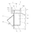
次に、図4を用いて従来の異なる例の蒸気タービンを説明する。ここで、図4は従来の異なる例の蒸気タービンを説明する説明図で、(a)はその要部を示す断面図であり、(b)は図4の(a)におけるB矢視図である。なお、図4(b)では図4(a)に示した締結体731の図示を省略している。なおまた、以下の説明においては、図2、図3に示した従来の一例の蒸気タービン9と同一部分には同じ符号を付し、その説明を省略する。図4にその要部を示した従来の異なる例の蒸気タービン9Aは、図2、図3により示した従来の一例の蒸気タービン9に対し、抽気室95の外周側に隣接させて、バランス管用の接続室部952を追加して設けるようにした蒸気タービンである。この事例の場合には、接続室部952は接続室部951(図4には不図示)に対して、外周板74の外周側にケーシング7の周方向に沿って、接続室部951の両側のそれぞれに隣接させて設けられている。それぞれの接続室部952は、外周板74,端板75,仕切板76,塞ぎ板77と,外周板74の外周側にケーシング7の周方向に沿って配設された不図示の隔壁板とによって周囲を区切ることで形成されており、内部には内部空間953が形成されている。この接続室部952は、外周板74に設けられた開口部742を介して抽気室95と連通されており、端板75の接続室部952を形成している部位には、内部空間953と連通させて、この事例の場合のバランス管64の接続相手であるバランス管用の接続部79が配設されている。
Next, another conventional steam turbine will be described with reference to FIG. Here, FIG. 4 is an explanatory view for explaining a conventional steam turbine of a different example, (a) is a cross-sectional view showing the main part thereof, (b) is a view as seen from arrow B in (a) of FIG. is there. In addition, in FIG.4 (b), illustration of the
蒸気タービン9Aを蒸気タービン9と対比すると、蒸気タービン9が抽気室95側のバランス管用の接続部として抽気管63を利用するのに対し、蒸気タービン9Aは抽気室95側のバランス管用の接続部として、バランス管専用の接続部79を持つと共に、この接続部79が配設された接続室部952を備えるようにしたことが相異点であると言うことができる。蒸気タービン9Aのように、抽気管用の接続部71(図4には不図示)とバランス管用の接続部79との両方を備えるようにした蒸気タービンは、抽気管63(図4には不図示)から供給する蒸気96(図4には不図示)の量が多い場合に一般的に採用されている。蒸気タービン9Aの場合の漏れ蒸気97の通流経路に関して述べると、バランス管64内を通流してきた漏れ蒸気97は、バランス管64から接続部79を経て接続室部952の内部空間953に流れ込み、さらに、開口部742から抽気室95に流れ込んで抽気室95内の蒸気と合流する。漏れ蒸気97の流入による抽気室95内の蒸気の状態の変化は、前述の蒸気タービン9のストップ弁62が閉じられた場合と全く同様に、漏れ蒸気97の有無によって実質的な影響を受けることはない。
When the
なお、蒸気タービン9Aも、蒸気タービン9の場合と同様に、いずれも図4には不図示の、低圧ヒータ61、ストップ弁62、ボイラ、ボイラ給水ポンプなどの補機類が備えられており、蒸気タービン9Aの通常運転時にはストップ弁62が開かれて抽気管63から低圧ヒータ61に蒸気96の供給が行われ、ストップ弁62が閉じられた場合には低圧ヒータ61への蒸気96の供給は停止される。そうして、蒸気タービン9Aの場合には、漏れ蒸気97の通流状態は蒸気タービン9の場合とは異なり、低圧ヒータ61への蒸気96の供給の有無には無関係に、蒸気タービン9Aの運転時には常にバランス管64→接続室部952(接続部79→内部空間953)→抽気室95の経路で通流する。そうして、前述した蒸気タービン9Aに関する説明から、蒸気96と漏れ蒸気97とに関わって接続室部952が果たす役目を整理すると、バランス管用の接続室部952は、バランス管64を介してバラストピストン82の部位に蒸気96を抽気室95から通気させると共に、バラストピストン82で発生した漏れ蒸気97をバランス管64を介して常時流入させて抽気室95に通流させるということになり、また、この場合のバランス管64は、バラストピストン82で発生した高温の漏れ蒸気97が常時通流する管路であるということができる。
前述した従来技術による蒸気タービン9,9Aでは、後記することが問題とされその解決が望まれている。まず、蒸気タービン9Aでは、その運転時には高温の漏れ蒸気97が、バランス管用の接続室部952に常時流入し、さらに開口部742から抽気室95に流れ込んでいる。このために、接続室部952には漏れ蒸気97が充満されて高温となり、これに伴って接続室部952に隣接している部位のフランジ73が部分的に高温となり、この部分的に高温となった部位のフランジ73に局部的に高い熱応力が発生する。低圧ケーシング7Bのフランジ73は、高中圧ケーシング7Aのフランジ78Aと六角ボルトなどの締結体731によって互いに締結されているが、前記局部的に高い熱応力の値やその発生状態によっては、局部的に高い熱応力による影響が締結体731による締結力を上回ってしまう懸念がある。もしも、局部的に高い熱応力による影響が締結体731による締結力を上回ってしまうと、この部位のフランジ73に局部的な熱変形が生じて蒸気漏れが生じてしまうことになる。したがって、接続室部952が漏れ蒸気97によって高温となる問題への対処が強く要望されている。
In the above-described
また、蒸気タービン9では、低圧ヒータ61の保守・点検作業の実施などのために低圧ヒータ61の運転を停止する際にストップ弁62が閉じられるが、ストップ弁62が閉じられると、バランス管64から抽気管63に流入している漏れ蒸気97は、抽気管63内を蒸気タービン9の通常運転時の場合とは逆方向に通流し、抽気管用の接続室部951に流入し、さらに、開口部741から抽気室95に流れ込むことになる。そうして、このことによって、接続室部951に漏れ蒸気97が充満されて高温となり、これに伴って接続室部951に隣接している部位のフランジ73に部分的に高温となる。このフランジ73が部分的に高温となることによって起こる問題は、蒸気タービン9Aに対して前記した内容と同様である。
蒸気タービン9では、高温の漏れ蒸気97によってフランジ73が部分的に高温になる問題は、蒸気タービン9Aの場合とは異なって、低圧ヒータ61を運転停止するという限定的な状態において発生する問題である。しかし、低圧ヒータ61の運転停止時にフランジ73に蒸気漏れが生じてしまうことになると、低圧ヒータ61の保守・点検時には蒸気タービン9を停止しなければならないことになり、蒸気タービン9の停止・再起動には多大な費用と時間を要するので、蒸気タービン9の場合でも、接続室部951が漏れ蒸気97によって高温となる問題への対処が強く要望されている。すなわち、接続室部951,接続室部952などの漏れ蒸気97が通流する管路が接続される接続室部を持つ従来例の蒸気タービン9,9Aは、接続室部に高温の漏れ蒸気97の流入があってもその周辺部に熱的影響を与えないようにするよう、強く要望されている。したがってこの発明の目的は、高温の漏れ蒸気が通流する管路が接続される接続室部に漏れ蒸気の流入があっても、その周辺部に熱的影響を与えないようにした蒸気タービンを提供することにある。
Further, in the
In the
この発明では前述の目的は、
1)高温・高圧の主蒸気が持つエネルギーを回転動力に変換してタービン軸を回転させると共にその回転動力へ変換する部分をケーシングで覆うようにした蒸気タービンであって、このタービン軸に備えられた円板状のバラストピストンの一方の面に高圧の前記主蒸気を与えると共に,他方の面にこの蒸気タービン内の前記主蒸気よりも低い圧力値を持つ低圧蒸気をバランス管を介して与えるようにした蒸気タービンにおいて、
前記低圧蒸気が存在している部位の前記ケーシングの外周板の外周側に形成された接続室部は、前記バランス管を介して前記バラストピストンの他方の面に与える前記低圧蒸気を通気させると共に,前記バラストピストンに一方の面の前記主蒸気の圧力と他方の面の低圧蒸気の圧力との圧力差によって生じた漏れ蒸気をバランス管を介して流入させて低圧蒸気が存在している部位に通流させるものであり、前記バランス管に接続されて前記低圧蒸気の通気と前記漏れ蒸気の通流とをバランス管との間で相互に行うようにする内管と、この内管との間に間隔が形成されるようにして内管を囲んで設けられた外管と、前記内管と前記外管とを管長方向の相対的な移動が可能なようにして気密に接続する薄板材製の支持体とを備え、この内管は前記バランス管に接続される端部とは反対側の端部を前記ケーシングの外周板に設けられた貫通口との間に間隙が形成されるようにしてこの貫通口を貫通させて前記低圧蒸気が存在している部位に突出させるようにしたこと、または、
2)前記1項に記載の手段において、前記接続室部はこの蒸気タービンの低圧ケーシング内に形成されている抽気室の部位の前記低圧ケーシングの外周板の外周側に形成され、前記低圧蒸気として前記抽気室内の低圧蒸気を前記バランス管に通気させるようにするものであることより達成される。
In the present invention, the aforementioned object is
1) A steam turbine in which the energy of high-temperature and high-pressure main steam is converted into rotational power to rotate the turbine shaft and the portion to be converted to the rotational power is covered with a casing, and is provided in this turbine shaft. The high-pressure main steam is applied to one surface of the disc-shaped ballast piston, and low-pressure steam having a pressure value lower than that of the main steam in the steam turbine is applied to the other surface via a balance pipe. In the steam turbine
The connection chamber portion formed on the outer peripheral side of the outer peripheral plate of the casing in the portion where the low-pressure steam is present allows the low-pressure steam to be given to the other surface of the ballast piston through the balance pipe, Leakage steam generated by the pressure difference between the pressure of the main steam on one surface and the pressure of the low pressure steam on the other surface is caused to flow into the ballast piston through a balance pipe and pass through a portion where low pressure steam exists. An inner pipe connected to the balance pipe to allow the low-pressure steam to flow and the leaked steam to flow between the balance pipe and the inner pipe. An outer tube provided to surround the inner tube so that an interval is formed, and a thin plate material that connects the inner tube and the outer tube in an airtight manner so that relative movement in the tube length direction is possible. A support body, the inner tube being A gap is formed between an end opposite to the end connected to the lance pipe and a through-hole provided in the outer peripheral plate of the casing so that the low-pressure steam passes through the through-hole. To project to the existing site, or
2) In the means described in 1 above, the connection chamber portion is formed on the outer peripheral side of the outer peripheral plate of the low pressure casing at a portion of the extraction chamber formed in the low pressure casing of the steam turbine. This is achieved by allowing the low-pressure steam in the extraction chamber to vent through the balance pipe.
この発明による蒸気タービンでは、前記課題を解決するための手段の項で述べた構成とすることで、次記の効果を得られる。まず、接続室部にバランス管から流入した高温の漏れ蒸気は、内管の管路内を通流して抽気室などの低圧蒸気の存在部位内に突出されたその先端部から低圧蒸気の存在部位内に吐出され、漏れ蒸気よりもかなり低温の低圧蒸気に直ちに合流して混じり合う。漏れ蒸気の流量は低圧蒸気の存在部位内の低圧蒸気の蒸気量に対してかなり少量なので、低圧蒸気の存在部位内の低圧蒸気の温度状態は漏れ蒸気の有無によって実質的な影響を受けることはない。また、内管の先端部が貫通される貫通口の内管との間に形成されている間隙から低圧蒸気の存在部位内の低圧蒸気が流入されることで、接続室部の内部空間は低温の低圧蒸気で満たされる。また、接続室部で漏れ蒸気が持つ高温の影響を直接受ける部位は、漏れ蒸気が通流する内管に限定することができる。 In the steam turbine according to the present invention, the following effects can be obtained by adopting the configuration described in the section for solving the problems. First, the high-temperature leaking steam that has flowed into the connection chamber from the balance pipe flows through the inner pipe line and protrudes into the existence area of the low-pressure steam such as the extraction chamber. It is discharged inside and immediately joins and mixes with low-pressure steam that is considerably cooler than leaked steam. Since the flow rate of the leaking steam is considerably smaller than the amount of low-pressure steam in the site where the low-pressure steam is present, the temperature state of the low-pressure steam in the site where the low-pressure steam is present is not substantially affected by the presence or absence of the leaking steam. Absent. In addition, the low-pressure steam in the portion where the low-pressure steam is present flows from a gap formed between the inner pipe of the through-hole through which the tip of the inner pipe penetrates, so that the internal space of the connection chamber portion has a low temperature. Filled with low pressure steam. Moreover, the site | part which receives the influence of the high temperature which a leaking steam has in a connection chamber part can be limited to the inner tube | pipe through which a leaking steam flows.
また、漏れ蒸気が持つ高温の影響を間接的に受ける部位は、内管に熱伝導的に接触したり,内管に近接して配置されたりしている部位のみに限定できる。前者は内管を支持する支持体などであるが、支持体は薄板材製のために支持面積を抑えることができると共に、内部空間内の低圧蒸気で冷却されることで、支持体の外管側の温度を、低圧蒸気の存在部位内の低圧蒸気が持つ温度値にかなり近い温度値に抑制することができる。後者は内管が開口部を貫通する部位であるが、内管と開口部との間には間隙が形成されていて両者の直接な接触が防止されると共に、この開口部が形成されている部材の前記内部空間を形成している部位では、その内部空間側の面は内部空間内の低圧蒸気で冷却され、その反内部空間側の面は低圧蒸気の存在部位内の低圧蒸気で冷却されることで、支持体の外管側の温度を、この場合にも、低圧蒸気の存在部位内の低圧蒸気が持つ温度値にかなり近い温度値に抑制することができる。 Moreover, the part which receives the influence of the high temperature which a leaking steam has indirectly can be limited only to the part which contact | connects an inner pipe thermally conductively, or is arrange | positioned close to the inner pipe. The former is a support that supports the inner tube, but the support is made of a thin plate material, so that the support area can be reduced, and the outer tube of the support is cooled by low-pressure steam in the internal space. The temperature on the side can be suppressed to a temperature value that is considerably close to the temperature value of the low-pressure steam in the site where the low-pressure steam is present. The latter is a part where the inner tube passes through the opening, but a gap is formed between the inner tube and the opening to prevent direct contact between the two, and this opening is formed. In the part forming the internal space of the member, the surface on the internal space side is cooled by the low-pressure steam in the internal space, and the surface on the anti-internal space side is cooled by the low-pressure steam in the site where the low-pressure steam exists. In this case, the temperature on the outer tube side of the support can be suppressed to a temperature value that is considerably close to the temperature value of the low-pressure steam in the site where the low-pressure steam exists.
すなわち、この発明の蒸気タービンの接続室部では、その外管の温度を内部空間内の低圧蒸気の温度、換言すると、前記低圧蒸気の存在部位内の低圧蒸気の温度とほぼ同等程度に保持することが可能になる。このことは、この発明による蒸気タービンでは、その接続室部にバランス管から高温の漏れ蒸気が流入される条件が常時であるか間欠的であるかに係わらず、接続室部の外管の温度を低圧蒸気の存在部位内の低圧蒸気の温度とほぼ同等程度の低温に保持することが可能になることを意味する。これにより、従来例の蒸気タービンで発生していた、接続室部への高温の漏れ蒸気の流入により、接続室部に隣接する部位のフランジが部分的に高温になることが原因での蒸気漏れ発生の懸念を完全に払拭することが可能になるとの効果を得られる。
また、この発明による蒸気タービンの接続室部の内管および外管は、蒸気タービンの運転状態などに従って生じるそれぞれの温度条件に応じてそれぞれに熱膨張をすることになるが、その結果、内管と外管との間にはそれ等の管長方向に相対的な移動が発生することになる。接続室部の支持体にはこの相対的な移動の結果が直接に加えられることになるが、支持体が薄板材製とされていることによって、さしたる応力の発生を伴うことなしに、この相対的な移動に追従することができる。すなわち、この発明による薄板材製の支持体を用いることによって、外管の高温化の抑制と、内管と外管との熱膨張差に基因して発生する応力の抑制とを、同時に得ることが可能になるとの効果を得られる。
That is, in the connection chamber portion of the steam turbine according to the present invention, the temperature of the outer pipe is maintained at substantially the same level as the temperature of the low-pressure steam in the internal space, in other words, the temperature of the low-pressure steam in the portion where the low-pressure steam is present. It becomes possible. This is because in the steam turbine according to the present invention, the temperature of the outer pipe of the connection chamber is not limited regardless of whether the high-temperature leaked steam from the balance pipe flows into the connection chamber at all times or intermittently. Can be maintained at a low temperature substantially equal to the temperature of the low-pressure steam in the site where the low-pressure steam is present. As a result, steam leakage caused by the inflow of high-temperature leaked steam into the connection chamber, which has occurred in the conventional steam turbine, is caused by the part of the flange adjacent to the connection chamber partially becoming hot. It is possible to obtain an effect that it is possible to completely eliminate the concern of occurrence.
Further, the inner pipe and the outer pipe of the connection chamber portion of the steam turbine according to the present invention each thermally expand in accordance with the respective temperature conditions generated according to the operating state of the steam turbine. As a result, the inner pipe A relative movement in the tube length direction occurs between the outer tube and the outer tube. The result of this relative movement is directly applied to the support in the connection chamber part, but since the support is made of a thin plate material, this relative movement can be achieved without generating any significant stress. Can follow a typical movement. That is, by using the support made of a thin plate material according to the present invention, it is possible to simultaneously obtain the suppression of the high temperature of the outer tube and the suppression of the stress generated due to the difference in thermal expansion between the inner tube and the outer tube. When it becomes possible, the effect is obtained.
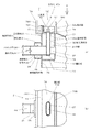
以下この発明を実施するための最良の形態を図1を参照して詳細に説明する。ここで図1は、この発明の実施の形態の一例による蒸気タービンを説明する説明図で、(a)はその要部を示す断面図であり、(b)は図1の(a)におけるA矢視図である。なお、図1(b)では図1(a)に示した締結体731,保護体などの図示を省略している。なおまた、以下の説明においては、図4に示した従来の異なる例による蒸気タービンと同一部分には同じ符号を付し、その説明を省略する。図1にその要部を示したこの発明の一例による蒸気タービン1は、図4により示した従来の異なる例の蒸気タービン9Aに対して、バランス管用の接続室部952に替えて、バランス管用の接続室部2を用いるようにした蒸気タービンである。接続室部2は、蒸気タービン9Aの接続室部952が配設されている部位と同一部位に、蒸気タービン9Aの場合と同様に、外周板74の外周側にケーシング7の周方向に沿って、抽気管用の接続室部951(図1には不図示)の両側のそれぞれに隣接させて配設されている。それぞれの接続室部2は、外周板74,端板75,仕切板76,塞ぎ板77と,外周板74の外周側にケーシング7の周方向に沿って配設された不図示の隔壁板とによって周囲を区切られて形成された室内空間953を備えていることは、従来例による接続室部952と同様である。
The best mode for carrying out the present invention will be described in detail with reference to FIG. Here, FIG. 1 is an explanatory view for explaining a steam turbine according to an example of an embodiment of the present invention, (a) is a cross-sectional view showing the main part thereof, and (b) is an A in FIG. It is an arrow view. In addition, in FIG.1 (b), illustration of the
接続室部2の場合のバランス管64の接続相手であるバランス管用の接続部31は、端板75の室内空間953を形成している部位に設けられた開口34を貫通し、室内空間953内に挿入されており、室内空間953のほぼ中央部付近で挿入用内管32に気密に接合されている。挿入用内管32は、この事例の場合には蒸気タービン1の軸長方向の寸法を増大させないようにする見地から小判形の断面形状を持たせ、その先端部32aは開口部742を貫通させて抽気室95内に突出され、接続部31とはその基部部分で気密に接合されている。なお、挿入用内管32の断面形状・寸法や開口部742の形状・寸法は、挿入用内管32の外周面と開口部742の内周面との間に所定寸法の間隙27が形成されるように設定されている。33は、挿入用内管32の先端部32aとは反対側の端部部分を気密に塞ぐ塞ぎ板である。接続部用外管25は、接続部31よりも大きな径を持つ管材を用いて接続部31とほぼ同心に配置され、端板75の反室内空間953側に開口34を覆うように装着されている。
The
支持体36は接続部31および接続部用外管25の板厚値よりも薄い板厚値を持つ薄板材製であり、接続部31と接続部用外管25との間隔を保持すると共に、接続部31と接続部用外管25とをその管長方向に相互移動が可能なようにして気密に支持する。37は、挿入用内管32を仕切板76に固定するための、必要に応じて設けられる固定体である。固定体37は、この事例の場合には、矩形状に成形された板材が使用され、一方の端部が挿入用内管32の接続部31が接合される側面とは反対側の側面の,接続部31の中心軸線にほぼ合致する部位に接合されると共に、他方の端部が仕切板76に気密に接合されている。保護体4は、挿入用内管32の先端部32aから抽気室95に吐出される漏れ蒸気97によって生じる高温の飛沫が、フランジ73や締結体731などに掛かるのを防ぐために必要に応じて設けられるもので、この事例の場合には薄板材製である。
The support 36 is made of a thin plate material having a plate thickness value that is smaller than the plate thickness value of the
以上のように構成されたバランス管用の接続室部2は、接続部31,挿入用内管32と塞ぎ板33とにより接続室部2全体としての内管部3が構成され、また、接続部用外管25と、室内空間953を形成する外周板74,端板75,仕切板76,塞ぎ板77,不図示の隔壁板とによって、接続室部2全体としての内管部3を囲む外管部2Aが構成されているとすることができる。この場合、内管部3の蒸気96を通気させると共に漏れ蒸気97を通流させる管路は、接続部31および挿入用内管32それぞれの内径部分である。そうして、内管部3と外管部2Aとを持つ接続室部2は、バランス管64が接続される端部側を支持体36によって気密に支持されることで、外管部2A,内管部3および支持体36によって囲まれた空間21が形成されることになる。なお、室内空間953による空間もこの空間21に含まれることになる。
In the
図1に示すこの発明の実施の形態の一例による蒸気タービン1ではバランス管用の接続室部2を前述の構成としたので、蒸気タービン1の場合には、バランス管用の接続室部2にバランス管64から流入した高温の漏れ蒸気97は、内管部3の管路内を通流して挿入用内管32の先端部32aから抽気室95内に吐出されることになる。接続室部2では挿入用内管32の先端部32aは抽気室95内に突出されて配置されているので、先端部32aから吐出された漏れ蒸気97は抽気室95内の蒸気〔この蒸気は蒸気96(図1には不図示)としても使用される蒸気で、漏れ蒸気97よりもかなり低温の蒸気である。〕に直ちに合流して混じり合う。従来例の蒸気タービン9,9Aの場合と同様に、漏れ蒸気97の流量は抽気室95内の蒸気量に対してかなり少量なので、抽気室95内の蒸気の温度状態は漏れ蒸気97の有無によって実質的な影響を受けることはない。また、従来例の蒸気タービン9Aの接続室部952の場合と異なって、接続室部2の空間21には抽気室95内の蒸気が間隙27から流入されるので、空間21内はこの低温の蒸気で満たされることになる。
In the
また、接続室部2で漏れ蒸気97が持つ高温の影響を直接受ける部位は、漏れ蒸気97が通流する内管部3に限定される。また、漏れ蒸気97が持つ高温の影響を間接的に受ける外管部2Aの部位は、内管部3に熱伝導的に接触したり,内管部3に近接して配置されたりしている部位である。接続室部2で内管部3と外管部2Aとが熱伝導的に接触したり,または近接して配置されたりする部位は、この事例のように固定体37が使用される場合であっても、支持体36で支持される部位、固定体37が接合される部位および、先端部32a付近の挿入用内管32が開口部742を貫通する部位の3個所に限定することができる。そうして、支持体36で支持される部位では、内管部3の接続部31はその全周を巡る長さで支持されているが支持体36が薄板材のために支持面積を抑えることができ、しかも支持体36の空間21側の全表面を空間21内の蒸気で冷却されることで、支持体36の外管部2A部側の温度を、抽気室95内の蒸気が持つ温度値にかなり近い温度値に抑制することができる。
Moreover, the part which receives the influence of the high temperature which the leaking
また、固定体37が接合される部位では、内管部3の挿入用内管32に接合される固定体37は、板材製のためにその接合面積はさして広いものではなく、しかも、固定体37がその両面を空間21内の蒸気で冷却されることで、固定体37の外管部2A部側の温度を、抽気室95内の蒸気が持つ温度値にかなり近い温度値に抑制することができる。さらに、挿入用内管32が開口部742を貫通する部位では、両者間には間隙27が形成されていて両者の直接な接触が防止されると共に、この開口部742が形成されている外周板74の空間21を形成している部位の空間21側の面は、空間21内の蒸気で冷却される。外周板74の空間21を形成している部位とは反空間21側の面は抽気室95内の蒸気で冷却されていることもあって、外周板74の空間21を形成している部位の温度を抽気室95内の蒸気が持つ温度値にかなり近い温度値に抑制することができる。すなわち、この発明の接続室部2では、その外管部2Aの温度を空間21内の蒸気の温度、換言すると、抽気室95内の蒸気の温度とほぼ同等程度の低温に保持することができる。
Further, in the portion where the fixing
このことは、この発明による蒸気タービン1のバランス管用の接続室部2では、バランス管64から高温の漏れ蒸気97が常時流入される条件であっても、外管部2Aの温度を抽気室95内の蒸気の温度とほぼ同等程度の低温に保持することができることを意味する。この外管部2Aは図1でも明らかなようにフランジ73に隣接して設けられているので、したがって、接続室部2に隣接している部位のフランジ73の温度は、他の部位のフランジ73の温度と同様に、抽気室95内の蒸気の温度とほぼ同等程度の低温に保持されることになり、従来例の蒸気タービン9Aで発生していたフランジ73が部分的に高温になるという事態が生じることはない。以上説明したことから、この発明による蒸気タービン1では、バランス管用の接続室部2に高温の漏れ蒸気97の流入があっても、接続室部2に隣接する部位のフランジ73が高温になることはなく、抽気室95内の蒸気の温度とほぼ同等程度の低温に保持される。これにより、従来例の蒸気タービン9Aで発生していた、バランス管用の接続室部への漏れ蒸気97の流入により、フランジ73が部分的に高温になることが原因での蒸気漏れ発生の懸念を完全に払拭することができる。
This is because, in the
なおまた、蒸気タービン1の運転状態などによって、接続室部2の内管部3と外管部2Aとは、その温度に応じて熱膨張することになるが、固定体37が使用されるこの事例の場合には、内管部3と外管部2Aの各部の熱膨張差はこの固定体37の接合部位をほぼ中心にして発生する。その結果、接続部31と接続部用外管25との間にはそれ等の管長方向に相対的な移動が発生することになる。支持体36にはこの相対的な移動の結果が直接に加えられることになるが、支持体36は前記したように薄板材製とされていることによって、さしたる応力の発生を伴うことなしに、この相対的な移動に追従することができる。すなわち、薄板材製の支持体36を用いることによって、外管部2Aの高温化の抑制と、接続部31と接続部用外管25との熱膨張差に基因して発生する応力の抑制とを、同時に得ることができることになる。
In addition, depending on the operating state of the
前述の説明では、蒸気タービンが備える接続室部はバランス管用であるとしてきたが、これに限定されるものではなく、例えば、抽気管用の接続室部であってもよいものである。抽気管用の接続室部にこの発明を適用することで、低圧ヒータ61の運転停止時であってもフランジ73に蒸気漏れが生じることがなくなるので、低圧ヒータ61の保守・点検時に蒸気タービンを停止することを不要にできる。
In the above description, the connection chamber part included in the steam turbine has been described as being for a balance pipe. However, the present invention is not limited to this. For example, the connection chamber part for an extraction pipe may be used. By applying the present invention to the connection chamber portion for the extraction pipe, steam leakage does not occur in the
1 蒸気タービン
2 接続室部
2A 外管部
21 空間
25 接続部用外管
3 内管部
31 接続部
32 挿入用内管
32a 先端部
33 塞ぎ板
36 支持体
64 バランス管
742 開口部
95 抽気室
953 室内空間
97 漏れ蒸気
DESCRIPTION OF
Claims (2)
前記低圧蒸気が存在している部位の前記ケーシングの外周板の外周側に形成された接続室部は、前記バランス管を介して前記バラストピストンの他方の面に与える前記低圧蒸気を通気させると共に,前記バラストピストンに一方の面の前記主蒸気の圧力と他方の面の低圧蒸気の圧力との圧力差によって生じた漏れ蒸気をバランス管を介して流入させて低圧蒸気が存在している部位に通流させるものであり、前記バランス管に接続されて前記低圧蒸気の通気と前記漏れ蒸気の通流とをバランス管との間で相互に行うようにする内管と、この内管との間に間隔が形成されるようにして内管を囲んで設けられた外管と、前記内管と前記外管とを管長方向の相対的な移動が可能なようにして気密に接続する薄板材製の支持体とを備え、この内管は前記バランス管に接続される端部とは反対側の端部を前記ケーシングの外周板に設けられた貫通口との間に間隙が形成されるようにしてこの貫通口を貫通させて前記低圧蒸気が存在している部位に突出させるようにしたことを特徴とする蒸気タービン。 A steam turbine that converts the energy of high-temperature, high-pressure main steam into rotational power to rotate the turbine shaft and covers the portion to be converted to the rotational power with a casing. The high-pressure main steam is supplied to one surface of the plate-shaped ballast piston, and low-pressure steam having a lower pressure value than the main steam in the steam turbine is supplied to the other surface via a balance pipe. In the steam turbine,
The connection chamber portion formed on the outer peripheral side of the outer peripheral plate of the casing in the portion where the low-pressure steam is present allows the low-pressure steam to be given to the other surface of the ballast piston through the balance pipe, Leakage steam generated by the pressure difference between the pressure of the main steam on one surface and the pressure of the low pressure steam on the other surface is caused to flow into the ballast piston through a balance pipe and pass through a portion where low pressure steam exists. An inner pipe connected to the balance pipe to allow the low-pressure steam to flow and the leaked steam to flow between the balance pipe and the inner pipe. An outer tube provided to surround the inner tube so that an interval is formed, and a thin plate material that connects the inner tube and the outer tube in an airtight manner so that relative movement in the tube length direction is possible. A support body, the inner tube being A gap is formed between an end opposite to the end connected to the lance pipe and a through-hole provided in the outer peripheral plate of the casing so that the low-pressure steam passes through the through-hole. A steam turbine characterized by projecting to an existing site.
Priority Applications (1)
| Application Number | Priority Date | Filing Date | Title |
|---|---|---|---|
| JP2005024993A JP4586552B2 (en) | 2005-02-01 | 2005-02-01 | Steam turbine |
Applications Claiming Priority (1)
| Application Number | Priority Date | Filing Date | Title |
|---|---|---|---|
| JP2005024993A JP4586552B2 (en) | 2005-02-01 | 2005-02-01 | Steam turbine |
Publications (2)
| Publication Number | Publication Date |
|---|---|
| JP2006214282A JP2006214282A (en) | 2006-08-17 |
| JP4586552B2 true JP4586552B2 (en) | 2010-11-24 |
Family
ID=36977724
Family Applications (1)
| Application Number | Title | Priority Date | Filing Date |
|---|---|---|---|
| JP2005024993A Expired - Lifetime JP4586552B2 (en) | 2005-02-01 | 2005-02-01 | Steam turbine |
Country Status (1)
| Country | Link |
|---|---|
| JP (1) | JP4586552B2 (en) |
Families Citing this family (1)
| Publication number | Priority date | Publication date | Assignee | Title |
|---|---|---|---|---|
| CN113685236B (en) * | 2021-08-23 | 2022-10-14 | 华能铜川照金煤电有限公司 | Balance piston device for single-cylinder single-row counter-pressure steam turbine with multiple speed stages |
Family Cites Families (2)
| Publication number | Priority date | Publication date | Assignee | Title |
|---|---|---|---|---|
| JP3052616B2 (en) * | 1992-11-06 | 2000-06-19 | 富士電機株式会社 | Pressure-balanced expansion joint for exhaust connection pipe |
| JP2002206407A (en) * | 2001-01-10 | 2002-07-26 | Fuji Electric Co Ltd | Axial exhaust type turbine device |
-
2005
- 2005-02-01 JP JP2005024993A patent/JP4586552B2/en not_active Expired - Lifetime
Also Published As
| Publication number | Publication date |
|---|---|
| JP2006214282A (en) | 2006-08-17 |
Similar Documents
| Publication | Publication Date | Title |
|---|---|---|
| JPS59229003A (en) | Main steam inlet structure of steam turbine | |
| JP5543029B2 (en) | Internal cooling system for turbomachine | |
| JP2010216468A (en) | Turbo supercharger | |
| RU2666828C2 (en) | Heat-shield manifold system for midframe case of gas turbine engine | |
| US9234431B2 (en) | Seal assembly for controlling fluid flow | |
| JP5756886B2 (en) | Steam turbine with thrust balance piston | |
| US6880338B2 (en) | Lead-in structure and a fixing flange for a turbo generator | |
| JP2019052641A (en) | Turbocharger | |
| JP6188777B2 (en) | Sealing device | |
| JP4586552B2 (en) | Steam turbine | |
| JP4256304B2 (en) | Twin-shaft gas turbine | |
| JP6189239B2 (en) | Steam turbine | |
| JPH0586901A (en) | Gas turbine | |
| JP4334142B2 (en) | Gas turbine structure | |
| JP3653993B2 (en) | Gland packing device for axial exhaust turbine | |
| JP6249927B2 (en) | Steam turbine | |
| JPH11350914A (en) | Outer casing cooling structure of steam turbine | |
| JP6637064B2 (en) | Axial turbine | |
| JP2004036527A (en) | Casing structure for steam turbine | |
| JP2018523043A (en) | Storage sleeve for turbomachine bearing and turbomachine provided with said sleeve | |
| CN108431375B (en) | Steam turbine cooling device | |
| JP5433535B2 (en) | Steam turbine | |
| JP2008540895A (en) | Steam turbine | |
| KR101855001B1 (en) | System for turbine's cooling and blocking leakage | |
| JP2003148109A (en) | Deformation amount adjusting device for steam turbine casing |
Legal Events
| Date | Code | Title | Description |
|---|---|---|---|
| RD02 | Notification of acceptance of power of attorney |
Free format text: JAPANESE INTERMEDIATE CODE: A7422 Effective date: 20060703 |
|
| RD04 | Notification of resignation of power of attorney |
Free format text: JAPANESE INTERMEDIATE CODE: A7424 Effective date: 20060704 |
|
| A621 | Written request for application examination |
Free format text: JAPANESE INTERMEDIATE CODE: A621 Effective date: 20071213 |
|
| RD02 | Notification of acceptance of power of attorney |
Free format text: JAPANESE INTERMEDIATE CODE: A7422 Effective date: 20081215 |
|
| RD04 | Notification of resignation of power of attorney |
Free format text: JAPANESE INTERMEDIATE CODE: A7424 Effective date: 20090219 |
|
| TRDD | Decision of grant or rejection written | ||
| A01 | Written decision to grant a patent or to grant a registration (utility model) |
Free format text: JAPANESE INTERMEDIATE CODE: A01 Effective date: 20100810 |
|
| A01 | Written decision to grant a patent or to grant a registration (utility model) |
Free format text: JAPANESE INTERMEDIATE CODE: A01 |
|
| A61 | First payment of annual fees (during grant procedure) |
Free format text: JAPANESE INTERMEDIATE CODE: A61 Effective date: 20100823 |
|
| R150 | Certificate of patent or registration of utility model |
Ref document number: 4586552 Country of ref document: JP Free format text: JAPANESE INTERMEDIATE CODE: R150 |
|
| FPAY | Renewal fee payment (event date is renewal date of database) |
Free format text: PAYMENT UNTIL: 20130917 Year of fee payment: 3 |
|
| FPAY | Renewal fee payment (event date is renewal date of database) |
Free format text: PAYMENT UNTIL: 20130917 Year of fee payment: 3 |
|
| S111 | Request for change of ownership or part of ownership |
Free format text: JAPANESE INTERMEDIATE CODE: R313111 |
|
| FPAY | Renewal fee payment (event date is renewal date of database) |
Free format text: PAYMENT UNTIL: 20130917 Year of fee payment: 3 |
|
| R350 | Written notification of registration of transfer |
Free format text: JAPANESE INTERMEDIATE CODE: R350 |
|
| R250 | Receipt of annual fees |
Free format text: JAPANESE INTERMEDIATE CODE: R250 |
|
| R250 | Receipt of annual fees |
Free format text: JAPANESE INTERMEDIATE CODE: R250 |
|
| R250 | Receipt of annual fees |
Free format text: JAPANESE INTERMEDIATE CODE: R250 |
|
| R250 | Receipt of annual fees |
Free format text: JAPANESE INTERMEDIATE CODE: R250 |
|
| R250 | Receipt of annual fees |
Free format text: JAPANESE INTERMEDIATE CODE: R250 |
|
| R250 | Receipt of annual fees |
Free format text: JAPANESE INTERMEDIATE CODE: R250 |
|
| R250 | Receipt of annual fees |
Free format text: JAPANESE INTERMEDIATE CODE: R250 |
|
| R250 | Receipt of annual fees |
Free format text: JAPANESE INTERMEDIATE CODE: R250 |
|
| R250 | Receipt of annual fees |
Free format text: JAPANESE INTERMEDIATE CODE: R250 |
|
| R250 | Receipt of annual fees |
Free format text: JAPANESE INTERMEDIATE CODE: R250 |
|
| R250 | Receipt of annual fees |
Free format text: JAPANESE INTERMEDIATE CODE: R250 |
|
| R250 | Receipt of annual fees |
Free format text: JAPANESE INTERMEDIATE CODE: R250 |
|
| EXPY | Cancellation because of completion of term |