EP2816187A2 - Wing frame of a window or a door with multilayered glazing - Google Patents
Wing frame of a window or a door with multilayered glazing Download PDFInfo
- Publication number
- EP2816187A2 EP2816187A2 EP20140150143 EP14150143A EP2816187A2 EP 2816187 A2 EP2816187 A2 EP 2816187A2 EP 20140150143 EP20140150143 EP 20140150143 EP 14150143 A EP14150143 A EP 14150143A EP 2816187 A2 EP2816187 A2 EP 2816187A2
- Authority
- EP
- European Patent Office
- Prior art keywords
- frame
- oblong
- wing
- adapter
- window
- Prior art date
- Legal status (The legal status is an assumption and is not a legal conclusion. Google has not performed a legal analysis and makes no representation as to the accuracy of the status listed.)
- Withdrawn
Links
- 239000011521 glass Substances 0.000 claims abstract description 73
- 230000015572 biosynthetic process Effects 0.000 claims abstract description 61
- 239000004411 aluminium Substances 0.000 claims abstract description 14
- 229910052782 aluminium Inorganic materials 0.000 claims abstract description 14
- XAGFODPZIPBFFR-UHFFFAOYSA-N aluminium Chemical compound [Al] XAGFODPZIPBFFR-UHFFFAOYSA-N 0.000 claims abstract description 14
- 238000005755 formation reaction Methods 0.000 claims description 57
- 239000002390 adhesive tape Substances 0.000 claims description 12
- 239000000945 filler Substances 0.000 claims description 4
- 230000001788 irregular Effects 0.000 claims 1
- 125000006850 spacer group Chemical group 0.000 description 14
- 238000010276 construction Methods 0.000 description 13
- 238000000034 method Methods 0.000 description 10
- 239000000565 sealant Substances 0.000 description 10
- 238000004026 adhesive bonding Methods 0.000 description 7
- 239000003292 glue Substances 0.000 description 7
- 230000007812 deficiency Effects 0.000 description 6
- 238000004519 manufacturing process Methods 0.000 description 6
- 239000000463 material Substances 0.000 description 4
- 239000004033 plastic Substances 0.000 description 4
- 229920003023 plastic Polymers 0.000 description 4
- 238000007789 sealing Methods 0.000 description 4
- 229920002635 polyurethane Polymers 0.000 description 3
- 239000004814 polyurethane Substances 0.000 description 3
- 239000002023 wood Substances 0.000 description 3
- OKTJSMMVPCPJKN-UHFFFAOYSA-N Carbon Chemical compound [C] OKTJSMMVPCPJKN-UHFFFAOYSA-N 0.000 description 2
- 229920002943 EPDM rubber Polymers 0.000 description 2
- 229920006328 Styrofoam Polymers 0.000 description 2
- 229910002804 graphite Inorganic materials 0.000 description 2
- 239000010439 graphite Substances 0.000 description 2
- 239000008261 styrofoam Substances 0.000 description 2
- 239000006096 absorbing agent Substances 0.000 description 1
- 239000003795 chemical substances by application Substances 0.000 description 1
- 238000005253 cladding Methods 0.000 description 1
- 238000004140 cleaning Methods 0.000 description 1
- 150000001875 compounds Chemical class 0.000 description 1
- 238000005516 engineering process Methods 0.000 description 1
- 239000011261 inert gas Substances 0.000 description 1
- 239000007788 liquid Substances 0.000 description 1
- 229910052751 metal Inorganic materials 0.000 description 1
- 239000002184 metal Substances 0.000 description 1
- 239000000203 mixture Substances 0.000 description 1
- 238000002360 preparation method Methods 0.000 description 1
- 229910052710 silicon Inorganic materials 0.000 description 1
- 239000010703 silicon Substances 0.000 description 1
- 229910001220 stainless steel Inorganic materials 0.000 description 1
- 239000010935 stainless steel Substances 0.000 description 1
- 239000005341 toughened glass Substances 0.000 description 1
- XLYOFNOQVPJJNP-UHFFFAOYSA-N water Substances O XLYOFNOQVPJJNP-UHFFFAOYSA-N 0.000 description 1
Images




Classifications
-
- E—FIXED CONSTRUCTIONS
- E06—DOORS, WINDOWS, SHUTTERS, OR ROLLER BLINDS IN GENERAL; LADDERS
- E06B—FIXED OR MOVABLE CLOSURES FOR OPENINGS IN BUILDINGS, VEHICLES, FENCES OR LIKE ENCLOSURES IN GENERAL, e.g. DOORS, WINDOWS, BLINDS, GATES
- E06B3/00—Window sashes, door leaves, or like elements for closing wall or like openings; Layout of fixed or moving closures, e.g. windows in wall or like openings; Features of rigidly-mounted outer frames relating to the mounting of wing frames
- E06B3/02—Wings made completely of glass
- E06B3/025—Wings made completely of glass consisting of multiple glazing units
-
- E—FIXED CONSTRUCTIONS
- E06—DOORS, WINDOWS, SHUTTERS, OR ROLLER BLINDS IN GENERAL; LADDERS
- E06B—FIXED OR MOVABLE CLOSURES FOR OPENINGS IN BUILDINGS, VEHICLES, FENCES OR LIKE ENCLOSURES IN GENERAL, e.g. DOORS, WINDOWS, BLINDS, GATES
- E06B3/00—Window sashes, door leaves, or like elements for closing wall or like openings; Layout of fixed or moving closures, e.g. windows in wall or like openings; Features of rigidly-mounted outer frames relating to the mounting of wing frames
- E06B3/30—Coverings, e.g. protecting against weather, for decorative purposes
- E06B3/301—Coverings, e.g. protecting against weather, for decorative purposes consisting of prefabricated profiled members or glass
- E06B3/302—Covering wooden frames with metal or plastic profiled members
-
- E—FIXED CONSTRUCTIONS
- E06—DOORS, WINDOWS, SHUTTERS, OR ROLLER BLINDS IN GENERAL; LADDERS
- E06B—FIXED OR MOVABLE CLOSURES FOR OPENINGS IN BUILDINGS, VEHICLES, FENCES OR LIKE ENCLOSURES IN GENERAL, e.g. DOORS, WINDOWS, BLINDS, GATES
- E06B3/00—Window sashes, door leaves, or like elements for closing wall or like openings; Layout of fixed or moving closures, e.g. windows in wall or like openings; Features of rigidly-mounted outer frames relating to the mounting of wing frames
- E06B3/30—Coverings, e.g. protecting against weather, for decorative purposes
- E06B3/301—Coverings, e.g. protecting against weather, for decorative purposes consisting of prefabricated profiled members or glass
- E06B3/306—Covering plastic frames with metal or plastic profiled members
-
- E—FIXED CONSTRUCTIONS
- E06—DOORS, WINDOWS, SHUTTERS, OR ROLLER BLINDS IN GENERAL; LADDERS
- E06B—FIXED OR MOVABLE CLOSURES FOR OPENINGS IN BUILDINGS, VEHICLES, FENCES OR LIKE ENCLOSURES IN GENERAL, e.g. DOORS, WINDOWS, BLINDS, GATES
- E06B3/00—Window sashes, door leaves, or like elements for closing wall or like openings; Layout of fixed or moving closures, e.g. windows in wall or like openings; Features of rigidly-mounted outer frames relating to the mounting of wing frames
- E06B3/30—Coverings, e.g. protecting against weather, for decorative purposes
- E06B3/308—Wing frames covered on the outside by a rigidly-mounted outer frame
Definitions
- the subject of the invention is a wing frame of a window or a door with multilayered glazing, or more precisely, a uniform profile wing frame with the corresponding seal to seal the slot between the internal glass and the window wing, and with the corresponding oblong formations for fixing internal and/or external adapters for building in a larger number of layers of insulating glasses, including cladding of external and/or internal wing surfaces with adapters in the sense of covering or decorating laths.
- this invention belongs to E06B 3/04, E06B 3/14 and, additionally, to E06B 3/30.
- the technical problem solved by this invention is such a construction of a uniform wing frame of a window or a door that will make it possible to quickly and simply fix appropriate internal and/or external adapters that will facilitate building in the glazing, consisting of several layers of insulating glass by using only one, for this purpose uniform and universal wing frame with an additional seal.
- appropriate adapters By inserting appropriate adapters into this uniform wing frame, it will be possible to produce windows and doors with multilayered glazing and with different thermal characteristics for new buildings as well as for improving existing already built in windows or doors.
- the thickness of the wing frame and the number of insulating glasses have a large impact upon thermal characteristics of windows and doors. Because of this the known doors and windows differ primarily by the thickness of the wing frame profile. The more glass layers are built into the wing, the thicker is the frame, which means that there are frames of different thicknesses. Thus, there are at least three standard thicknesses of wing frame profiles: 68 mm, 78 mm and 88 mm. Because of this the known solutions of producing windows and doors with multilayered glazing are based on the request to assure the production of wing frames of windows and doors of different thicknesses, which is additionally conditional upon the production of different tools for working on them. Because of this the preparation phase and the production are longer, which significantly increases production costs.
- the so called compound window produced by Internorm is known, for the construction of which it is characteristic that it consists of an additional hollow aluminium profile, which is fixed on hinges. These hinges make it possible to open together the glass glued to the aluminium profile and the aluminium profile, which makes it possible to clean the dirt or condensed liquid, which is often present in case of such solutions as the chamber between the third and the fourth glass is not airtight.
- the spacer between glass plates also functions as a wing frame of a window.
- the spacer has one shoulder on each side and in the space between the glasses, double-sided adhesive tape coated with a humidity absorber is inserted. Weakness and deficiency of this solution is above all in the fact that the frame constructed in such a way does not enable the flexibility of building three, four or more glasses into a window wing.
- a glazed panel is according to the patent WO 96/16245 , which consists of a frame, glazed with two glass plates and an airtight chamber between them.
- the frame is of a profile construction with corresponding seals. Weakness and deficiency of this solution is above all in the fact that the frame is constructed in such a way that it does not enable flexible fixing of adapters on the internal and external side of a window wing and it also does not make it possible to build three, four or more glasses into the wing frame.
- the production of such a window wing with an airtight chamber between the glasses is very complicated and it is practically very difficult to produce it according to a modern technological procedure.
- the next known solution is according to the patent DE 298 12 574 , which includes a profile wing frame of a window consisting of two metal parts, which are connected with a supporting element between them. Two glass plates with a spacer between them, separated from the two-part frame by a gluing agent, are fixed into and next to the profile frame. The glasses are fixed to the spacer with a layer of glue. Weakness and deficiency of this solution is above all in the fact that it does not make it possible to build in an adapter on the internal and/or external side of the wing frame, because of which it is impossible to build in two, three or more layers of insulating glass and, consequently, it is impossible to achieve better energy efficiency.
- the common characteristic of all the described known solutions of wing frames of windows and doors is above all in the fact that their structures do not enable the flexibility of building in three, four or more layers of insulating glass, while using a uniform profile frame. Because of this window and door frames of various thicknesses are used in practice, depending on the number of layers of built in insulating glass. The common characteristic is also the problem of positioning the internal glass, during and after the procedure of gluing it to the window and door wing, with additional spacers and uneven slot between the edge of the internal glass and the edge of the window or door wing, which is formed during this.
- a uniform wing frame of a window or door is required, which will make it possible to produce a wing with optional multilayered glazing and in relation to which the procedure of positioning of glasses during the gluing procedure with additional spacers will no longer be necessary.
- the described technical problem is resolved with a window or door frame, the structure of which is such that it enables flexible building in of two-, three-, four- or more layered insulating glass in such a way that it ensures the achievement of a high level of energy efficiency and airtight sealing.
- the characteristic of the window or door frame is a uniform construction, regardless of the number of built in insulating glasses, which is made possible by a profile structure, characteristic of it with at least one, two or more oblong formations for fixing suitable adapters.
- the main characteristic of this innovative solution of a window or door frame is its transverse or longitudinal section, which is indicated by at least one oblong formation for fixing at least one adapter and a multifunction seal along the side leg.
- Fixing of at least one or more suitable adapters to a uniform wing frame makes it possible to produce a window or a door with two, three, four or more built in insulating glasses, with very good thermal characteristics.
- the shape and the width of the window wing are the same for all the constructions of window or door wings.
- This solution according to the invention simplifies a uniform and standard frame construction as well as the procedure of producing it and in this way, it reduces production costs.
- a uniform frame with one or two oblong formations and preferentially with only two adapters are required.
- the wing frame of a window or a door is preferentially made from hard PVC, which has, at the edge of one of its side legs, a multifunction seal, preferentially made of EPDMA.
- the procedure preferentially used to apply the seal to the frame leg is coextrusion.
- the outline of the wing frame of a window or a door with the abovementioned seal is formed in such a way that the seal protects the edge of the internal insulating glass, facilitating its simple positioning onto the window or door wing, and at the same time, the seal also automatically seals the slot between the internal glass and the window or door wing.
- the first feasibility example of the frame 2 of a window wing 40 is made from an oblong profile, which, in a transverse section, forms a comb consisting of optional geometrical chambers and of which an oblong protrusion 34 with a leg 27 and an oblong protrusion 42 with a leg 26 are typical, which preferentially are located along the entire length of the frame 2.
- the leg 27 lies preferentially perpendicularly to the oblong protrusion 34, whereas the leg 26 is parallel with the oblong protrusion 42.
- the free end of the leg 27 is constructed as an oblong formation 28 with an oblong slot 7 and a groove 41, which are preferentially located along the entire length of the frame 2.
- the oblong protrusion 33 with a seal 1 is located at the free end of the leg 26 and perpendicularly to it.
- the seal 1 is, with the free longitudinal edge turned back against the leg 26 under an optional angle.
- the oblong protrusion 33 with the seal 1 is preferentially located along the entire length of the leg 26 and, in this way, also along the entire length of the frame 2.
- a frame 2 is presented that differs from the frame 2 presented in Fig. 7 only by having, in addition to the oblong formation 28 on the leg 27, an oblong formation 29 on the leg 30, which are located diametrically opposite to one another and are preferentially of the same shape.
- the oblong formation 29 also has a groove 41 at the top; it also has an oblong slot 7, which is constructed in such a way that it forms a close contact with the oblong formations 31 inserted into it for adapters 6, 17, 24 and 38, which is a precondition for their sides being parallel and/or perpendicular to the glazing 39.
- the adapter 38 is constructed as an oblong lath, which has, on its larger plane and along its entire length, an oblong formation 31 with a slot 32, above which a slot 35 is located and beneath it slots 36 and 37. This is presented in Fig. 9 .
- the adapters 6 and 17 are preferentially of the same construction as the adapter 38, in particular in reference to its oblong formation 31 with the slot 32. The only differences are in their position towards the frame 2 and in their shapes.
- the frame 2 can be constructed with at least one or two oblong formations 28 and/or 29, which can be positioned in a different way in some other feasibility example. Similarly, in some other feasibility example, the frame 2 can be constructed with several oblong formations 28 and/or 29.
- the entire frame 2 is preferentially made of hard PVC, and the seal 1 of EPDM and is applied to the oblong protrusion 33 preferentially by using the process of coextrusion.
- the frame 2 and the seal 1 can be made of other suitable materials, and the seal 1 can be applied to the oblong protrusion 33 also by using some other procedure and/or can be produced separately prior to this and then glued to the oblong protrusion 33 or fixed to it in some other way.
- the frame 2 is fixed to the window wing 40 in such a way that the oblong formation 28 is positioned on the external wing 40, whereas the oblong formation 29 is positioned on the internal wing 40.
- a vertical adapter 24 is put on the oblong formation 28 of the frame 2 at the external side of the window wing 40 so that it abuts against the insulating glass 3.2 with the double-sided adhesive tape between them.
- the adapter 24 is covered with an aluminium profile 11, which is on one side fixed to the ratchet 14 on the external side of the window frame, preferentially made of wood 12 and on the other side it abuts against the adapter 24 via the seal 22.
- the aluminium profile 11 is filled with the insulating filler 21 along the entire length, which significantly improves thermal characteristics in this area of the window wing 40.
- the three-layered glazing 39 consists of the insulating glasses 3, 3.1 and 3.2.
- the inter-glass spacers 15 and 15.1 are inserted between the insulating glasses 3, 3.1 and 3.2 so that they are located on a layer of the secondary sealant 9 and 9.1, respectively.
- the three-layered glazing 39 is fixed to the window frame 2 in such a way that, with the glasses 3.1 and 3.2, it abuts against the shim 20 and a glue layer, preferentially polyurethane 25, respectively, and with the lower edge of the glass 3 on the seal 1.
- the insulating glass 3.2 is positioned next to the adapter 24 on the external side of the window wing 40, whereas the insulating glass 3 is positioned on the internal side of the window wing 40 so that, with its entire lower edge, it tightly abuts against the seal 1 and is glued to the internal side of the window frame 2 with the double-sided adhesive tape 4 and in this way it completes the internal appearance of the wing 40 of the observed window.
- the double-sided adhesive tape 23, on which the adapter 24 is glued, which is put on the oblong formation 28 of the frame 2, ensures a reliable joint between the insulating glass 3.2 and the window frame 2.
- the window wing 40 abuts against the window frame 12 along its entire circumference.
- the sealing between the window wing 40 and the window frame 12 is ensured by the seals 13 and 16, which are located on the oblong protrusion 34 or on the leg 26 of the oblong protrusion 42.
- the insulating glass 3 can be, on the internal side of the window wing 40, limited with the vertical adapter 38, which is presented in relation to the two-layered and four-layered glazing 39 below, in relation to the second and the third feasibility example.
- the adapter 38 with the oblong formation 31 is put into the oblong slot 7 of the adapter 29 on the window frame 2 and similarly, it is glued to it with the double-sided adhesive tape 4.
- the second feasibility example of the window wing 40 with the frame 2 according to the invention with two-layered glazing 39 is presented in Fig. 3 and in Fig. 4 .
- the area between the insulating glass 3.1 and the seal 22, which is inserted into the aluminium profile 11, is filled with the adapter 17.
- the aluminium profile 11 covers the adapter 17 in a similar way as previously described in relation to the first feasibility example.
- the adapter 17 is preferentially filled with the insulating filler 18, which is preferentially made of graphite styrofoam. In this way the thermal characteristics in the area of inter-glass spacer 15 and the secondary sealant 9 is significantly improved.
- the two-layered glazing 39 consists of the insulating glasses 3 and 3.1 and the inter-glass spacer 15, and a layer of the secondary sealant 9 inserted between them.
- the two-layered glazing 39 is fixed to the window frame in such a way that, with the glasses 3 and 3.1, it abuts on the polyurethane glue layer 25, which is located on the upper surface of the window frame 2.
- the insulating glass 3 is positioned next to the adapter 38, which is put on the oblong formation 29 of the window frame 2 on the internal side of the window wing 40 and in this way it completes the internal appearance of the wing 40 of the observed window.
- the adapter 38 with the oblong formation 31 is put into the oblong slot 7 of the oblong formation 29 on the window frame 2 and glued on it with the double-sided adhesive tape 4.
- the sealing of the wing 40 at the wood window frame 12 is ensured with the seals 13 and 16 as described in relation to the first feasibility example.
- the third feasibility example of the window wing 40 with the frame 2 according to the invention and with a four-layered glazing 39 is presented in Fig. 5 and in Fig. 6 .
- the horizontal adapter 6, with which the longitudinal side of the wing 40 is lengthened in such a way that four insulating glasses 3, 3.1, 3.2 and 3.3 can be glued on it, is put on the oblong formation 28 of the frame 2 on the external side of the window wing 40.
- the distance between the insulating glasses 3, 3.1, 3.2 and 3.3 is determined with the inter-glass spacers 15, 15.1 and 15.2, which are, on the lower side, limited with the secondary sealant 9, 9.1 and 9.2.
- the glazing 39 assembled in such a way is inserted into the window wing 40 in such a way that the insulating glass 3 is, on the internal side of the wing 40, positioned on or next to the vertical adapter 38, which is fixed to the oblong formation 29 of the frame 2.
- the adapter 38 is fixed to the oblong formation 29 by means of the oblong formation 31, which is inserted into the oblong slot 7 of the oblong formation 29 of the window frame 2 so that, with its longer lower edge, it tightly abuts against the seal 1 on the oblong protrusion 33 of the leg 26 in the lower part of the frame 2.
- the seal 1 enables correct positioning of the adapter 38 and of the glazing 39 on the window frame 2 within the assembly of the wing 40.
- the double-sided adhesive tape 4 is placed, which prevents the adapter 38 from falling out and, at the same time, it enables a reliable joint between the frame 2 and the adapter 38.
- the two-component polyurethane glue layer 5 and 5.1 is applied. Then the horizontal adapter 6 is put on the internal oblong formation 28 of the window frame 2 in the longitudinal direction so that its unmarked oblong protrusion is pushed into the oblong slot 7 on the external oblong formation 28 of the window frame 2.
- the shim 8 is used, which is preferentially made of plastics.
- the adapter 6 On its lower side, the adapter 6 abuts against the seal 10, which is preferentially made of EDPM and is, along with the seals 13 and 16, intended to ensure the required airtightness and water tightness between the window wing 40 and the window frame 12.
- the seal 10 is inserted into the unmarked slot on the upper side of the aluminium profile 11. It applies for this feasibility example with the horizontal adapter 6 that the number of glass layers of the glazing 39 above the window frame 2 can also be larger, e.g. there can be five layers or more, which depends on the width of the adapter 6.
- the insulating glass 3 can be fixed on the internal side of the wing 40 and glued to the frame 2 with the adhesive tape 4.
- two structures of the frame 2 can be used: only with the external oblong formation 28 or with the external oblong formation 28 and the internal oblong formation 29 at the same time. Therefore, the frame 2 with the oblong formation 28 and/or with the oblong formation 29 can be used.
- the adapter 38 which is via the oblong formation 31 put on or into the internal oblong formation 29 of the frame 2, can be fixed to the internal wing 40.
- the frame 2 with both oblong formations 28 and 29 is used as a rule.
- One of the adapters 6, 17 or 24 can be placed on the oblong formation 28 of the frame 2 on the external side of the wing 40, depending on the number of layers of the glazing 39.
- the adapter 24 is preferentially used for a three-layered construction of the window or door wing 40, with insulating glasses 3, 3.1 and 3.2.
- the adapter 17 is preferentially used for a two-layered construction with the insulating glasses 3 and 3.1.
- the adapter 6 is preferentially used.
- seals 1, 10, 13, 16, 19 and 22 are preferentially made of EPDM
- window frames 2 of PVC insulating glasses 3, 3.1, 3.2 and 3.3 of toughened glass
- adapters 6, 17, 24 and 38 of aluminium shims 8 of plastics
- profiles 11 of aluminium ratchets 14 of plastics
- inter-glass spacers 15 15.1 and 15.2 preferentially of plastics, but also of aluminium or stainless steel
- insulating fillers 18 and 21 of graphite styrofoam are preferentially made of wood.
- window or door wings 40 can also be made of other suitable materials or of a combination of various materials.
Landscapes
- Engineering & Computer Science (AREA)
- Civil Engineering (AREA)
- Structural Engineering (AREA)
- Securing Of Glass Panes Or The Like (AREA)
Abstract
The frame of a window or a door with multilayered glazing solves the technical problem of a typed bearing frame (2), which will be, in combination with suitable adapters (6,17, 24, 38) useful for the wings (40) of a window or a door with multilayered glazing (39), regardless of the number of insulating glasses (3 to 3.n). The frame (2) is constructed as an oblong comb profile, which is characterized by oblong formation (28) and/or the oblong formation (29) in the upper part and the leg (26) with the seal (1) in the lower part. The oblong formation (28) is positioned on the external side of the wing (40) and the oblong formation (29) on the internal side of the wing (40). The internal side of the wing (40) can be finished with the insulating glass (3) or the adapter (38), whereas the external side with the aluminium profile (11).
Description
- The subject of the invention is a wing frame of a window or a door with multilayered glazing, or more precisely, a uniform profile wing frame with the corresponding seal to seal the slot between the internal glass and the window wing, and with the corresponding oblong formations for fixing internal and/or external adapters for building in a larger number of layers of insulating glasses, including cladding of external and/or internal wing surfaces with adapters in the sense of covering or decorating laths.
- According to the international patent classification this invention belongs to
E06B 3/04,E06B 3/14 and, additionally, toE06B 3/30. - The technical problem solved by this invention is such a construction of a uniform wing frame of a window or a door that will make it possible to quickly and simply fix appropriate internal and/or external adapters that will facilitate building in the glazing, consisting of several layers of insulating glass by using only one, for this purpose uniform and universal wing frame with an additional seal. By inserting appropriate adapters into this uniform wing frame, it will be possible to produce windows and doors with multilayered glazing and with different thermal characteristics for new buildings as well as for improving existing already built in windows or doors.
- There are many known solutions of constructions of wing frames of windows and doors with multilayered glazing. It is characteristic for them that the problem of positioning the internal glass during and after the procedure of gluing it to the window and door wing with additional spacers remains unsolved, the consequence of which is an uneven slot between the edge of the internal glass and the edge of the window wing. For sealing and aesthetics reasons, after gluing, this slot is usually filled with silicon or some other suitable sealant. The procedure of aesthetic filling of the slot is time-consuming, besides it must be followed by additional cleaning of window or door surfaces, which were in contact with the sealant.
- It is known that the thickness of the wing frame and the number of insulating glasses have a large impact upon thermal characteristics of windows and doors. Because of this the known doors and windows differ primarily by the thickness of the wing frame profile. The more glass layers are built into the wing, the thicker is the frame, which means that there are frames of different thicknesses. Thus, there are at least three standard thicknesses of wing frame profiles: 68 mm, 78 mm and 88 mm. Because of this the known solutions of producing windows and doors with multilayered glazing are based on the request to assure the production of wing frames of windows and doors of different thicknesses, which is additionally conditional upon the production of different tools for working on them. Because of this the preparation phase and the production are longer, which significantly increases production costs.
- On the market, the so called compound window produced by Internorm is known, for the construction of which it is characteristic that it consists of an additional hollow aluminium profile, which is fixed on hinges. These hinges make it possible to open together the glass glued to the aluminium profile and the aluminium profile, which makes it possible to clean the dirt or condensed liquid, which is often present in case of such solutions as the chamber between the third and the fourth glass is not airtight.
- The next known solution is according to the patent
SI 22343 - According to the patent
SI 22760 - Another known solution of a glazed panel is according to the patent
WO 96/16245 - The next known solution is according to the patent
DE 298 12 574 , which includes a profile wing frame of a window consisting of two metal parts, which are connected with a supporting element between them. Two glass plates with a spacer between them, separated from the two-part frame by a gluing agent, are fixed into and next to the profile frame. The glasses are fixed to the spacer with a layer of glue. Weakness and deficiency of this solution is above all in the fact that it does not make it possible to build in an adapter on the internal and/or external side of the wing frame, because of which it is impossible to build in two, three or more layers of insulating glass and, consequently, it is impossible to achieve better energy efficiency. Furthermore, weakness and deficiency of this solution is also in the fact that the protection of the edge of the internal glass and of the internal edge of the longer side of the window wing is foreseen by a coat of glue or of a sealant. Furthermore, its weakness and deficiency is in the composition of a two-layered insulating glass and in gluing it to the wing profile. Gluing is namely carried out through the wing profile; the secondary sealant has a double function: that of a glue and that of a sealant. In practice it is very difficult to glue through the profile if the slot between the window wing and the inter-glass spacer is to be fully filled. Therefore, it often happens in concern to such window frames that the inert gas, which is located between the glasses, escapes. - The common characteristic of all the described known solutions of wing frames of windows and doors is above all in the fact that their structures do not enable the flexibility of building in three, four or more layers of insulating glass, while using a uniform profile frame. Because of this window and door frames of various thicknesses are used in practice, depending on the number of layers of built in insulating glass. The common characteristic is also the problem of positioning the internal glass, during and after the procedure of gluing it to the window and door wing, with additional spacers and uneven slot between the edge of the internal glass and the edge of the window or door wing, which is formed during this.
- In view of all this, a uniform wing frame of a window or door is required, which will make it possible to produce a wing with optional multilayered glazing and in relation to which the procedure of positioning of glasses during the gluing procedure with additional spacers will no longer be necessary.
- According to the invention, the described technical problem is resolved with a window or door frame, the structure of which is such that it enables flexible building in of two-, three-, four- or more layered insulating glass in such a way that it ensures the achievement of a high level of energy efficiency and airtight sealing. The characteristic of the window or door frame is a uniform construction, regardless of the number of built in insulating glasses, which is made possible by a profile structure, characteristic of it with at least one, two or more oblong formations for fixing suitable adapters.
- The main characteristic of this innovative solution of a window or door frame is its transverse or longitudinal section, which is indicated by at least one oblong formation for fixing at least one adapter and a multifunction seal along the side leg.
- Fixing of at least one or more suitable adapters to a uniform wing frame makes it possible to produce a window or a door with two, three, four or more built in insulating glasses, with very good thermal characteristics. In this case, the shape and the width of the window wing are the same for all the constructions of window or door wings. This solution according to the invention simplifies a uniform and standard frame construction as well as the procedure of producing it and in this way, it reduces production costs. For a door or a window wing constructed in such a way, a uniform frame with one or two oblong formations and preferentially with only two adapters are required.
- The wing frame of a window or a door is preferentially made from hard PVC, which has, at the edge of one of its side legs, a multifunction seal, preferentially made of EPDMA. The procedure preferentially used to apply the seal to the frame leg is coextrusion. The outline of the wing frame of a window or a door with the abovementioned seal is formed in such a way that the seal protects the edge of the internal insulating glass, facilitating its simple positioning onto the window or door wing, and at the same time, the seal also automatically seals the slot between the internal glass and the window or door wing.
- The invention will be more precisely described in relation to the feasibility examples presented in the enclosed figures, which show as follows:
-
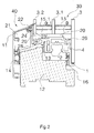
Fig. 1 wing frame of a window or a door according to the invention with three-layered glazing, in projection, first feasibility example; -
Fig. 2 same as inFig. 1 , but in front view; -
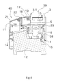
Fig. 3 wing frame of a window or a door according to the invention with two-layered glazing, in projection, second feasibility example; -
Fig. 4 same as inFig. 3 , only in front view; -
Fig. 5 wing frame of a window or a door according to the invention with four-layered glazing, in projection, third feasibility example; -
Fig. 6 same as inFig. 5 , only in front view; -
Fig. 7 wing frame with one oblong formation for an adapter, first feasibility example, in projection; -
Fig. 8 wing frame with two oblong formations for an adapter, second feasibility example, in projection; -
Fig. 9 adapter as a decorative lath, in projection. - Below is the description of the invention based on the
frame 2 of a window ordoor wing 40 withmultilayered glazing 39, presented on the basis of three feasibility examples, with three-layered, two-layered and four-layered glazing. To simplify the description, the description of these feasibility examples refers to theframe 2 of awindow wing 40, however, identical constructions refer also to glazed door wings, in particular, for balconies. - As presented in
Fig. 7 , the first feasibility example of theframe 2 of awindow wing 40 is made from an oblong profile, which, in a transverse section, forms a comb consisting of optional geometrical chambers and of which anoblong protrusion 34 with aleg 27 and anoblong protrusion 42 with aleg 26 are typical, which preferentially are located along the entire length of theframe 2. Theleg 27 lies preferentially perpendicularly to theoblong protrusion 34, whereas theleg 26 is parallel with theoblong protrusion 42. The free end of theleg 27 is constructed as anoblong formation 28 with anoblong slot 7 and agroove 41, which are preferentially located along the entire length of theframe 2. At the free end of theleg 26 and perpendicularly to it, theoblong protrusion 33 with aseal 1 is located. Theseal 1 is, with the free longitudinal edge turned back against theleg 26 under an optional angle. Theoblong protrusion 33 with theseal 1 is preferentially located along the entire length of theleg 26 and, in this way, also along the entire length of theframe 2. - In
Fig. 8 , aframe 2 is presented that differs from theframe 2 presented inFig. 7 only by having, in addition to theoblong formation 28 on theleg 27, anoblong formation 29 on theleg 30, which are located diametrically opposite to one another and are preferentially of the same shape. Similarly as theoblong formation 28, theoblong formation 29 also has agroove 41 at the top; it also has anoblong slot 7, which is constructed in such a way that it forms a close contact with theoblong formations 31 inserted into it foradapters glazing 39. - The
adapter 38 is constructed as an oblong lath, which has, on its larger plane and along its entire length, anoblong formation 31 with aslot 32, above which aslot 35 is located and beneath itslots Fig. 9 . - In concern to fixing to
oblong formations door frame 2, theadapters adapter 38, in particular in reference to itsoblong formation 31 with theslot 32. The only differences are in their position towards theframe 2 and in their shapes. - Based on previously presented and described facts, it is evident that the
frame 2 can be constructed with at least one or twooblong formations 28 and/or 29, which can be positioned in a different way in some other feasibility example. Similarly, in some other feasibility example, theframe 2 can be constructed with severaloblong formations 28 and/or 29. - The
entire frame 2 is preferentially made of hard PVC, and theseal 1 of EPDM and is applied to theoblong protrusion 33 preferentially by using the process of coextrusion. In some other feasibility example, theframe 2 and theseal 1 can be made of other suitable materials, and theseal 1 can be applied to theoblong protrusion 33 also by using some other procedure and/or can be produced separately prior to this and then glued to theoblong protrusion 33 or fixed to it in some other way. - It applies for the presented and described feasibility examples that the
frame 2 is fixed to thewindow wing 40 in such a way that theoblong formation 28 is positioned on theexternal wing 40, whereas theoblong formation 29 is positioned on theinternal wing 40. - The first feasibility example of the
window wing 40 with theframe 2 according to the invention and with a three-layered glazing is presented inFig. 1 and inFig. 2 . For this feasibility example, avertical adapter 24 is put on theoblong formation 28 of theframe 2 at the external side of thewindow wing 40 so that it abuts against the insulating glass 3.2 with the double-sided adhesive tape between them. Theadapter 24 is covered with analuminium profile 11, which is on one side fixed to theratchet 14 on the external side of the window frame, preferentially made ofwood 12 and on the other side it abuts against theadapter 24 via theseal 22. As a rule, in its upper part, thealuminium profile 11 is filled with the insulatingfiller 21 along the entire length, which significantly improves thermal characteristics in this area of thewindow wing 40. - The three-layered
glazing 39 consists of the insulatingglasses 3, 3.1 and 3.2. Theinter-glass spacers 15 and 15.1 are inserted between the insulatingglasses 3, 3.1 and 3.2 so that they are located on a layer of thesecondary sealant 9 and 9.1, respectively. In this assembly, the three-layeredglazing 39 is fixed to thewindow frame 2 in such a way that, with the glasses 3.1 and 3.2, it abuts against theshim 20 and a glue layer, preferentiallypolyurethane 25, respectively, and with the lower edge of theglass 3 on theseal 1. In relation to this, the insulating glass 3.2 is positioned next to theadapter 24 on the external side of thewindow wing 40, whereas the insulatingglass 3 is positioned on the internal side of thewindow wing 40 so that, with its entire lower edge, it tightly abuts against theseal 1 and is glued to the internal side of thewindow frame 2 with the double-sidedadhesive tape 4 and in this way it completes the internal appearance of thewing 40 of the observed window. - The double-sided
adhesive tape 23, on which theadapter 24 is glued, which is put on theoblong formation 28 of theframe 2, ensures a reliable joint between the insulating glass 3.2 and thewindow frame 2. - The
window wing 40 abuts against thewindow frame 12 along its entire circumference. The sealing between thewindow wing 40 and thewindow frame 12 is ensured by theseals oblong protrusion 34 or on theleg 26 of theoblong protrusion 42. - In some other feasibility example, which is not presented in relation to the previously described three-layered
glazing 39 of thewindow wing 40 with theframe 2, the insulatingglass 3 can be, on the internal side of thewindow wing 40, limited with thevertical adapter 38, which is presented in relation to the two-layered and four-layeredglazing 39 below, in relation to the second and the third feasibility example. For this feasibility example, it applies that theadapter 38 with theoblong formation 31 is put into theoblong slot 7 of theadapter 29 on thewindow frame 2 and similarly, it is glued to it with the double-sidedadhesive tape 4. - The second feasibility example of the
window wing 40 with theframe 2 according to the invention with two-layeredglazing 39 is presented inFig. 3 and inFig. 4 . In relation to this feasibility example, avertical adapter 17, which has aseal 19 built in on the other side, through which it tightly abuts on the external insulating glass 3.1, is put on theoblong formation 28 of theframe 2. In this way the area between the insulating glass 3.1 and theseal 22, which is inserted into thealuminium profile 11, is filled with theadapter 17. Thealuminium profile 11 covers theadapter 17 in a similar way as previously described in relation to the first feasibility example. Theadapter 17 is preferentially filled with the insulatingfiller 18, which is preferentially made of graphite styrofoam. In this way the thermal characteristics in the area ofinter-glass spacer 15 and thesecondary sealant 9 is significantly improved. - The two-layered
glazing 39 consists of the insulatingglasses 3 and 3.1 and theinter-glass spacer 15, and a layer of thesecondary sealant 9 inserted between them. In relation to this assembly, the two-layeredglazing 39 is fixed to the window frame in such a way that, with theglasses 3 and 3.1, it abuts on thepolyurethane glue layer 25, which is located on the upper surface of thewindow frame 2. In relation to this, the insulatingglass 3 is positioned next to theadapter 38, which is put on theoblong formation 29 of thewindow frame 2 on the internal side of thewindow wing 40 and in this way it completes the internal appearance of thewing 40 of the observed window. In relation to this feasibility example, theadapter 38 with theoblong formation 31 is put into theoblong slot 7 of theoblong formation 29 on thewindow frame 2 and glued on it with the double-sidedadhesive tape 4. - The sealing of the
wing 40 at thewood window frame 12 is ensured with theseals - The third feasibility example of the
window wing 40 with theframe 2 according to the invention and with a four-layeredglazing 39 is presented inFig. 5 and inFig. 6 . In relation to this feasibility example, thehorizontal adapter 6, with which the longitudinal side of thewing 40 is lengthened in such a way that four insulatingglasses 3, 3.1, 3.2 and 3.3 can be glued on it, is put on theoblong formation 28 of theframe 2 on the external side of thewindow wing 40. The distance between the insulatingglasses 3, 3.1, 3.2 and 3.3 is determined with theinter-glass spacers 15, 15.1 and 15.2, which are, on the lower side, limited with thesecondary sealant 9, 9.1 and 9.2. Theglazing 39 assembled in such a way is inserted into thewindow wing 40 in such a way that the insulatingglass 3 is, on the internal side of thewing 40, positioned on or next to thevertical adapter 38, which is fixed to theoblong formation 29 of theframe 2. Theadapter 38 is fixed to theoblong formation 29 by means of theoblong formation 31, which is inserted into theoblong slot 7 of theoblong formation 29 of thewindow frame 2 so that, with its longer lower edge, it tightly abuts against theseal 1 on theoblong protrusion 33 of theleg 26 in the lower part of theframe 2. Thereby theseal 1 enables correct positioning of theadapter 38 and of theglazing 39 on thewindow frame 2 within the assembly of thewing 40. In the unmarked longitudinal slot of theframe 2, the double-sidedadhesive tape 4 is placed, which prevents theadapter 38 from falling out and, at the same time, it enables a reliable joint between theframe 2 and theadapter 38. - After placing the
glazing 39 into the slot between thewindow frame 2 and thesecondary sealant 9, 9.1 and 9.2 andadapter 38, the two-componentpolyurethane glue layer 5 and 5.1 is applied. Then thehorizontal adapter 6 is put on the internaloblong formation 28 of thewindow frame 2 in the longitudinal direction so that its unmarked oblong protrusion is pushed into theoblong slot 7 on the externaloblong formation 28 of thewindow frame 2. To additionally fix theadapter 6 on theframe 2, the shim 8 is used, which is preferentially made of plastics. On its lower side, theadapter 6 abuts against theseal 10, which is preferentially made of EDPM and is, along with theseals window wing 40 and thewindow frame 12. Theseal 10 is inserted into the unmarked slot on the upper side of thealuminium profile 11. It applies for this feasibility example with thehorizontal adapter 6 that the number of glass layers of theglazing 39 above thewindow frame 2 can also be larger, e.g. there can be five layers or more, which depends on the width of theadapter 6. - It applies for all previously described feasibility examples of the
frame 2 of the window ordoor wing 40 withmultilayered glazing 39 that in relation to some feasibility examples the insulatingglass 3 can be fixed on the internal side of thewing 40 and glued to theframe 2 with theadhesive tape 4. In relation to this feasibility example, two structures of theframe 2 can be used: only with the externaloblong formation 28 or with the externaloblong formation 28 and the internaloblong formation 29 at the same time. Therefore, theframe 2 with theoblong formation 28 and/or with theoblong formation 29 can be used. - In other feasibility examples, the
adapter 38, which is via theoblong formation 31 put on or into the internaloblong formation 29 of theframe 2, can be fixed to theinternal wing 40. In these feasibility examples, theframe 2 with both oblongformations - One of the
adapters oblong formation 28 of theframe 2 on the external side of thewing 40, depending on the number of layers of theglazing 39. For a three-layered construction of the window ordoor wing 40, with insulatingglasses 3, 3.1 and 3.2, theadapter 24 is preferentially used. For a two-layered construction with the insulatingglasses 3 and 3.1, theadapter 17 is preferentially used. For a four-layered construction with the insulatingglasses 3, 3.1, 3.2 and 3.3, or for a construction with more than four layers, theadapter 6 is preferentially used. - Component parts of window or
door wings 40 are preferentially made of the following materials:seals window frames 2 of PVC, insulatingglasses 3, 3.1, 3.2 and 3.3 of toughened glass,adapters inter-glass spacers 15, 15.1 and 15.2 preferentially of plastics, but also of aluminium or stainless steel, insulatingfillers door frames 12 are preferentially made of wood. - It is fully understandable that the listed component parts of window or
door wings 40 can also be made of other suitable materials or of a combination of various materials.
Claims (12)
- The wing frame of a window or a door with multilayered glazing is characterised by the fact that the frame (2), which encompasses the entire circumference of the wing (40), is constructed with at least one external oblong formation (28) and/or at least one internal oblong formation (29) for fixing the adapter (6) and/or adapter (38) and/or adapter (24) and/or adapter (17), and that the frame (2) has, preferentially along its entire length, at least one seal (1) on the oblong protrusion (33) of the leg (26); that, in some feasibility examples, the insulating glass (3), which is glued to the frame (2) with the adhesive tape (4), is fixed on the internal side of the wing (40) at the frame (2) and that, in some other feasibility examples, also the vertical adapter (38), which is via the oblong formation (31) put into or on the oblong formation (29) on the frame (2) and at the same time also glued to it with the adhesive tape (4), can be fixed on the internal side of the wing (40), wherein the insulating glass (3) and the adapter (38), with their longer lower edge, are tightly about on the seal (1); that, on the oblong formation (28) on the frame (2) on the external side of the wing (40), one of the adapters (6) or (17) or (24) is fixed, depending on the number of glass layers in the glazing (39).
- The frame according to Claim 1 is characterised by the fact that the frame (2) is constructed as an oblong profile, which, in the transverse section, forms a comb made of chambers of optional regular or irregular geometric shapes, wherein at least one oblong protrusion (34) with the leg (27) and at least one oblong protrusion (42) with the leg (26), which as a rule are positioned along the entire length of the frame (2) and along the entire circumference of the wing (40), are typical of.
- The frame according to Claim 2 is characterised by the fact that the free ends of the leg (27) and/or of the leg (30) are preferentially finished with the oblong formation (28) and/or with the oblong formation (29) with the oblong slot (7) and the groove (41).
- The frame according to Claim 1 is characterised by the fact that the oblong formations (28) and (29) are preferentially placed diametrically opposite from each other, oriented one from the other in the opposite direction.
- The frame according to Claim 3 is characterised by the fact that the oblong slot (7) is constructed in such a way that it enables close contact with the oblong formations (31) of the adapters (6, 17, 24, 38), inserted into it.
- The frame according to Claim 1 is characterised by the fact that the frame (2) is placed into the wing (40) in such a way that the oblong formation (28) is positioned on the external side of the wing (40) and the oblong formation (29) on the internal side of the wing (40).
- The frame according to Claim 1 is characterised by the fact that the vertical adapter (24) is put on the oblong formation (28) of the frame (2) in such a way that it abuts, with the adhesive tape (24) between them, against the insulating glass (3.2) and is covered with the aluminium profile (11), which is, with one end, fixed to the ratchet (14) on the frame (12) of a door or a window and, with the other end, it abuts against the adapter (24) via the seal (22).
- The frame according to Claim 1 is characterised by the fact that the vertical adapter (17) is put on the oblong formation (28) of the frame (2) so that it tightly abuts against the external insulating glass (3.1) with the seal (19) between them, wherein the adapter (17) is preferentially filled with the insulating filler (18).
- The frame according to Claim 1 is characterised by the fact that the length of the horizontal adapter (6), which is put onto or into the oblong formation (28) on the frame (2), depends on the number of the layers of glass inside of the glazing (39), wherein in this way the longitudinal side of the wing (40) is lengthened appropriately.
- The frame according to Claim 9 is characterised by the fact that the adapter (6), on its underside, tightly abuts against the seal (10), which is inserted into the unmarked slot on the upper side of the aluminium profile (11).
- The frame according to Claim 1 is characterised by the fact that the seal (1) enables correct and precise positioning of the adapter (38) and insulating glass (3) of the glazing (39) to the frame (2) of the wing (40).
- The frame according to Claim 11 is characterised by the fact that the firm joint between the insulating glass (3.2) and the frame (2) is enabled with the adhesive tape (23), onto which the adapter (24), which is put on the oblong formation (28) of the frame (2), is glued.
Applications Claiming Priority (1)
| Application Number | Priority Date | Filing Date | Title |
|---|---|---|---|
| SI201300160A SI24024A (en) | 2013-06-17 | 2013-06-17 | Sash or door leaf with multilayer vitrification |
Publications (1)
| Publication Number | Publication Date |
|---|---|
| EP2816187A2 true EP2816187A2 (en) | 2014-12-24 |
Family
ID=49228574
Family Applications (1)
| Application Number | Title | Priority Date | Filing Date |
|---|---|---|---|
| EP20140150143 Withdrawn EP2816187A2 (en) | 2013-06-17 | 2014-01-03 | Wing frame of a window or a door with multilayered glazing |
Country Status (3)
| Country | Link |
|---|---|
| EP (1) | EP2816187A2 (en) |
| RU (1) | RU2014121728A (en) |
| SI (1) | SI24024A (en) |
Cited By (2)
| Publication number | Priority date | Publication date | Assignee | Title |
|---|---|---|---|---|
| EP3228795A1 (en) | 2016-04-07 | 2017-10-11 | Stolbud Wloszczowa Spólka Akcyjna | Wooden window or door assembly with an external covering |
| US10982484B2 (en) | 2018-06-22 | 2021-04-20 | Pella Corporation | Enhanced field of view for fenestration units |
Citations (2)
| Publication number | Priority date | Publication date | Assignee | Title |
|---|---|---|---|---|
| WO1996016245A1 (en) | 1994-11-22 | 1996-05-30 | Quisten Limited | Glazing panel |
| DE29812574U1 (en) | 1997-08-02 | 1998-11-05 | Vegla Vereinigte Glaswerke Gmbh, 52066 Aachen | Frameless window or door sash |
-
2013
- 2013-06-17 SI SI201300160A patent/SI24024A/en not_active IP Right Cessation
-
2014
- 2014-01-03 EP EP20140150143 patent/EP2816187A2/en not_active Withdrawn
- 2014-05-28 RU RU2014121728/12A patent/RU2014121728A/en not_active Application Discontinuation
Patent Citations (2)
| Publication number | Priority date | Publication date | Assignee | Title |
|---|---|---|---|---|
| WO1996016245A1 (en) | 1994-11-22 | 1996-05-30 | Quisten Limited | Glazing panel |
| DE29812574U1 (en) | 1997-08-02 | 1998-11-05 | Vegla Vereinigte Glaswerke Gmbh, 52066 Aachen | Frameless window or door sash |
Cited By (3)
| Publication number | Priority date | Publication date | Assignee | Title |
|---|---|---|---|---|
| EP3228795A1 (en) | 2016-04-07 | 2017-10-11 | Stolbud Wloszczowa Spólka Akcyjna | Wooden window or door assembly with an external covering |
| US10982484B2 (en) | 2018-06-22 | 2021-04-20 | Pella Corporation | Enhanced field of view for fenestration units |
| US12163372B2 (en) | 2018-06-22 | 2024-12-10 | Pella Corporation | Enhanced field of view for fenestration units |
Also Published As
| Publication number | Publication date |
|---|---|
| SI24024A (en) | 2013-09-30 |
| RU2014121728A (en) | 2015-12-10 |
Similar Documents
| Publication | Publication Date | Title |
|---|---|---|
| EP3568560B1 (en) | Semi-invisible combination for sliding doors which allows the unhindered passage | |
| US10107027B1 (en) | Thermally enhanced multi-component window | |
| US12091906B2 (en) | Thermally enhanced multi-component glass doors and windows | |
| US9453366B2 (en) | Window assemblies including bronze elements | |
| EP3201414B1 (en) | Openable frameless door or window casement arrangement with insulated glazing | |
| KR101784360B1 (en) | Variable composition door frame of window | |
| US11391083B1 (en) | Composite fenestration assembly | |
| EP3228795A1 (en) | Wooden window or door assembly with an external covering | |
| US20080256896A1 (en) | Glazing with a Stepped Pane Element Cemented to a Frame | |
| WO1986001249A1 (en) | Frames | |
| US7836643B2 (en) | Window | |
| GB2514213A (en) | Seal element, assembly, and method | |
| CN211342433U (en) | High-angle-strength energy-saving heat-preservation wood-aluminum composite door and window | |
| EP3721024B1 (en) | Curtain wall | |
| KR200498175Y1 (en) | Door and window including the same | |
| EP2589740B1 (en) | Device for clamping a glazing in a window or door frame | |
| EP3748116B1 (en) | Window or door | |
| KR102478576B1 (en) | Dual composition sliding window | |
| RU2566493C1 (en) | Shape and system of shapes for translucent structures | |
| EP2975206B1 (en) | Reinforced profile for sash frames and set of profiles for window frames and sash frames | |
| SI24024A (en) | Sash or door leaf with multilayer vitrification | |
| RU157890U1 (en) | WINDOW BLOCK | |
| CN111255353A (en) | Split type fireproof section bar and corresponding embedded aluminum-clad steel fireproof window | |
| CN206468191U (en) | A kind of full glass Rimless casement window | |
| CN109746671A (en) | A kind of packaging technology of embedded sliding door and window |
Legal Events
| Date | Code | Title | Description |
|---|---|---|---|
| PUAI | Public reference made under article 153(3) epc to a published international application that has entered the european phase |
Free format text: ORIGINAL CODE: 0009012 |
|
| 17P | Request for examination filed |
Effective date: 20140103 |
|
| AK | Designated contracting states |
Kind code of ref document: A2 Designated state(s): AL AT BE BG CH CY CZ DE DK EE ES FI FR GB GR HR HU IE IS IT LI LT LU LV MC MK MT NL NO PL PT RO RS SE SI SK SM TR |
|
| AX | Request for extension of the european patent |
Extension state: BA ME |
|
| STAA | Information on the status of an ep patent application or granted ep patent |
Free format text: STATUS: THE APPLICATION HAS BEEN WITHDRAWN |
|
| 18W | Application withdrawn |
Effective date: 20150714 |