EP2815900A1 - Trailer coupling - Google Patents
Trailer coupling Download PDFInfo
- Publication number
- EP2815900A1 EP2815900A1 EP14176932.3A EP14176932A EP2815900A1 EP 2815900 A1 EP2815900 A1 EP 2815900A1 EP 14176932 A EP14176932 A EP 14176932A EP 2815900 A1 EP2815900 A1 EP 2815900A1
- Authority
- EP
- European Patent Office
- Prior art keywords
- ball neck
- ball
- trailer coupling
- coupling according
- excitation
- Prior art date
- Legal status (The legal status is an assumption and is not a legal conclusion. Google has not performed a legal analysis and makes no representation as to the accuracy of the status listed.)
- Granted
Links
- 230000008878 coupling Effects 0.000 title claims abstract description 85
- 238000010168 coupling process Methods 0.000 title claims abstract description 85
- 238000005859 coupling reaction Methods 0.000 title claims abstract description 85
- 230000001133 acceleration Effects 0.000 claims abstract description 71
- 238000001514 detection method Methods 0.000 claims abstract description 26
- 230000001960 triggered effect Effects 0.000 claims abstract description 16
- 238000011156 evaluation Methods 0.000 claims description 47
- 230000005284 excitation Effects 0.000 claims description 44
- 230000004913 activation Effects 0.000 claims description 9
- 230000002123 temporal effect Effects 0.000 claims description 6
- 238000000034 method Methods 0.000 claims description 5
- 238000005259 measurement Methods 0.000 claims description 4
- 230000008054 signal transmission Effects 0.000 claims description 4
- 230000005540 biological transmission Effects 0.000 claims description 3
- 230000008569 process Effects 0.000 claims description 3
- 238000013017 mechanical damping Methods 0.000 claims description 2
- 230000000903 blocking effect Effects 0.000 description 34
- 230000006399 behavior Effects 0.000 description 13
- 230000006870 function Effects 0.000 description 6
- 230000008859 change Effects 0.000 description 4
- 230000010358 mechanical oscillation Effects 0.000 description 4
- 238000006243 chemical reaction Methods 0.000 description 3
- 230000002349 favourable effect Effects 0.000 description 3
- 230000008901 benefit Effects 0.000 description 2
- 238000013016 damping Methods 0.000 description 2
- 238000006073 displacement reaction Methods 0.000 description 2
- 238000004519 manufacturing process Methods 0.000 description 2
- 238000012544 monitoring process Methods 0.000 description 2
- 206010039203 Road traffic accident Diseases 0.000 description 1
- 230000037007 arousal Effects 0.000 description 1
- 230000000694 effects Effects 0.000 description 1
- 230000007613 environmental effect Effects 0.000 description 1
- 238000007654 immersion Methods 0.000 description 1
- 230000002452 interceptive effect Effects 0.000 description 1
- 238000001208 nuclear magnetic resonance pulse sequence Methods 0.000 description 1
- 230000010355 oscillation Effects 0.000 description 1
- 230000009467 reduction Effects 0.000 description 1
- 238000001228 spectrum Methods 0.000 description 1
- 230000003068 static effect Effects 0.000 description 1
- 230000001629 suppression Effects 0.000 description 1
- 230000001360 synchronised effect Effects 0.000 description 1
- 230000007704 transition Effects 0.000 description 1
Images


Classifications
-
- B—PERFORMING OPERATIONS; TRANSPORTING
- B60—VEHICLES IN GENERAL
- B60D—VEHICLE CONNECTIONS
- B60D1/00—Traction couplings; Hitches; Draw-gear; Towing devices
- B60D1/01—Traction couplings or hitches characterised by their type
- B60D1/06—Ball-and-socket hitches, e.g. constructional details, auxiliary devices, their arrangement on the vehicle
-
- B—PERFORMING OPERATIONS; TRANSPORTING
- B60—VEHICLES IN GENERAL
- B60D—VEHICLE CONNECTIONS
- B60D1/00—Traction couplings; Hitches; Draw-gear; Towing devices
- B60D1/48—Traction couplings; Hitches; Draw-gear; Towing devices characterised by the mounting
- B60D1/54—Traction couplings; Hitches; Draw-gear; Towing devices characterised by the mounting collapsible or retractable when not in use, e.g. hide-away hitches
-
- B—PERFORMING OPERATIONS; TRANSPORTING
- B60—VEHICLES IN GENERAL
- B60D—VEHICLE CONNECTIONS
- B60D1/00—Traction couplings; Hitches; Draw-gear; Towing devices
- B60D1/58—Auxiliary devices
- B60D1/62—Auxiliary devices involving supply lines, electric circuits, or the like
Definitions
- the invention relates to a towing hitch for motor vehicles, comprising a vehicle-fixed holding unit, a ball neck, which is connected in a working position in the region of a first end with a holding unit, and a coupling ball, which is arranged at a second end of the ball neck.
- an acceleration detection unit detects externally triggered accelerations acting on the ball neck by means of a sensor.
- Such accelerations triggering impulse may arise, for example, that the trailer coupling with the vehicle is involved in an accident together.
- Another type of acceleration may be caused by the vehicle being moved even though it is parked and locked.
- the acceleration detection unit compares the measured values of the externally triggered pulses with reference values.
- the stored reference values make it possible to ignore all irrelevant accelerations detected by the sensor.
- the measured values generated by externally triggered accelerations are stored.
- Such a storage of the measured values can be carried out, for example, directly in the acceleration detection unit.
- Another advantageous possibility provides that a transmission of a signal when an externally triggered acceleration occurs.
- Such a transmission of a signal can be, for example, the transmission of a signal via a mobile network to a mobile device, so that the vehicle owner can be informed about his mobile device in the event that his parked and closed vehicle is involved in an accident.
- an operation of the evaluation unit after attaching a trailer which can be recognized, for example, that an electrical connection between the electrical system of the motor vehicle and the supply network of the trailer is made.
- the evaluation unit can be activated for a certain period of time after such a connection of electrical system and supply network and - possibly still with the vehicle - detect the load on the ball neck, so that it is a pure static load, which is detected by the evaluation and is determined.
- the evaluation unit according to the invention can also be activated during driving to detect, for example, loads on the ball neck during driving, especially during acceleration and deceleration of the motor vehicle, and to determine these loads, for example, to trigger a Verspann istsmodus a Verspann tenuung.
- the acceleration detection unit can be activated during the driving operation of the motor vehicle, so that accelerations during the driving operation and possibly also an accident occurring during the driving operation can be detected.
- the acceleration detection unit can also be activated when the motor vehicle is stationary, in particular when the vehicle is parked and locked, in order to be able to detect accidents occurring in this state of the vehicle or even a theft.
- a sensor is arranged on the ball neck, detects the generated by an excitation in the ball neck mechanical vibrations and the vibrations corresponding measurement values generated, and that cooperating with the sensor evaluation unit is provided which determines the mechanical damping of the coupling ball in the working position from the behavior of the mechanical vibrations in the ball neck.
- the advantage of the solution according to the invention is the fact that by measuring the behavior of the mechanical vibrations there is an easy way to analyze the behavior of the ball neck when generated by an excitation mechanical vibrations and to draw conclusions about the extent to which the ball neck and the coupling ball are burdened by an attacking object.
- the invention is based on the assumption that, in a ball neck, the mechanical vibrations generated by excitation in the unloaded state of the ball neck and in the loaded state of the ball neck each have a different behavior.
- Such a different behavior of the mechanical vibrations may on the one hand be a lower amplitude under load, compared to the unloaded state and / or a modified decay behavior in the loaded state relative to the unloaded state and / or another frequency of self-adjusting vibrations in the loaded state relative to the unloaded Status.
- the evaluation unit compares the measured values with stored reference values.
- the load on the coupling ball and the ball neck can be determined with sufficient accuracy by comparison with reference values recorded during a calibration procedure.
- the evaluation unit determines whether the coupling ball and the ball neck are significantly loaded and / or whether the load is within a predetermined range or within predetermined ranges or outside thereof.
- the sensor can be any type of vibration sensor.
- a particularly expedient solution provides that the sensor is an acceleration sensor with which vibrations in the intended frequency range can be detected particularly favorably.
- the frequencies can be in the audible range.
- the frequencies are higher than 500Hz, even better higher than 1kHz to interference to reduce.
- An upper limit of the frequency range is 15 kHz in a preferred case.
- the acceleration sensor is in the simplest case, for example, not directionally selective.
- the evaluation of the sensor signals can be improved if the sensor detects directional accelerations, in particular a first direction in the direction of travel a second direction transverse, in particular at right angles to the direction of travel and a third direction transversely, in particular at right angles to the direction of travel and transversely to the second direction.
- the excitation of the ball neck is effected by an activation of an excitation generating process by a excitation control unit of the trailer coupling.
- the energization is triggered by the excitation control unit specifically, on the basis of which then the mechanical vibrations arise whose behavior can be evaluated in order to determine the load on the coupling ball and the ball neck.
- the excitation of the ball neck to mechanical vibrations could for example be done without contact via an electrical or magnetic coupling.
- Such a mechanical excitation can take place, for example, in that the exciter control unit triggers at least one pulse acting on the ball neck.
- the pulse is not triggered immediately adjacent to the sensor, but preferably it is provided that the pulse acts on the ball neck at a distance from the sensor, so that the mechanical vibrations over a significant area, that is, for example, at least one-fifth of the ball neck across before they are detected by the sensor.
- the distance can be produced, for example, in that the excitation takes place in the region of one of the ends of the ball neck and that the sensor is arranged in a central region of the ball neck.
- the distance is at least a quarter, more preferably a third, of the length of the ball neck between its ends.
- Such a mechanical excitation can be achieved, for example, by the exciter control unit actuating a vibration generator.
- the exciter control unit drives a pulse generator.
- the excitation control unit controls a blocking device for fixing the ball neck to the holding part in the sense of bracing thereof and thereby generates a mechanical excitation of mechanical vibrations in the ball neck.
- the evaluation of the measured values could be carried out continuously without correlation to the excitation of the mechanical vibrations in the ball neck.
- a particularly advantageous solution provides that the evaluation unit evaluates the measured values in their temporal relation to the excitation of the ball neck.
- a particularly favorable solution provides that the evaluation unit detects and evaluates the transmission of the mechanical vibrations in the ball neck. This means that the evaluation relates to which frequency or Amplitude values has a mechanical vibration in the ball neck after a defined excitation.
- Another advantageous solution provides that the evaluation evaluates a decay of the mechanical vibrations in the ball neck, that is, that the evaluation based on how the Abkling the mechanical vibrations in the ball neck is to draw conclusions about the mechanical stress of the ball neck ,
- a first embodiment of a trailer coupling according to the invention for a motor vehicle K shown in FIG Fig. 1 and 2 in a working position A and in Fig. 3 in a rest position R, comprises a designated as a whole with 10 ball neck, which is held with a first end 12 to a pivot bearing body 14 and at a second end 16 as a whole with 18 designated coupling ball carries, on which a coupling ball receiving a trailer is fixable.
- the pivot bearing body 14 is pivotally mounted about a pivot axis 22 relative to a vehicle-fixed carrier 24 by a generally designated 20 and formed as a pivot bearing unit holding unit, wherein the carrier 24 preferably has a holding unit formed as a pivot bearing unit 20 holding support plate 26 which preferably in a plane perpendicular to the pivot axis 22 extends and a vehicle-fixed cross member 28 which is fastened in a known manner to the rear of a vehicle body KA, in such a way that the pivot bearing unit 20 and the carrier 24 are on a side facing away from a road surface F side of a lower edge 30 of a bumper unit 36 , and are covered by the bumper unit 36 ( Fig. 4 ).
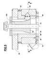
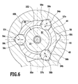
- the pivot bearing unit 20 includes, as in Fig. 5 and 6 shown, a guide body 40 which is fixedly connected to the flange 26 with a support plate 26 and a extending from the flange 42 of the support plate 26 away guide sleeve 44, on which the pivot bearing body 14 is rotatably mounted.
- the guide sleeve 44 comprises a cylindrical outer circumferential surface 46, on which the pivot bearing body 14 rests with a cylindrical inner surface 48 and thereby experiences about the pivot axis 22 a rotation guide, so that the pivot bearing body 14 is rotatable relative to the guide body 40 such that the ball neck 10 of the Working position A in the rest position R and vice versa is pivotable.
- the guide body 40 thus forms by its fixed connection with the support plate 26 and the carrier 24, the vehicle-fixed pivot bearing for the pivot bearing body fourteenth
- the pivot bearing unit 20 is provided with a designated as a whole with 50 rotational blocking device, which comprises an actuating body 52, a plurality acted upon by the actuating body 52 Wheelblockier Sciences 54, such as balls, which in guide receptacles 56 of the guide sleeve 44 in a substantially radially to the pivot axis 22 extending guide direction 57 are movably guided, and starting from the inner surface 48 of the pivot bearing body 14 in this hineinertiernde first receptacles 58 and second receptacles 60, with which the Drehblockier Sciences 54 in the working position A and in the Rest position R can be brought into engagement, wherein the receptacles 58, 60 in the radial direction to the pivot axis 22 increasingly have a smaller distance from each other having wall surfaces 59, 61 have.
- the wall surfaces 59, 61 extend toward one another as conical surfaces.
- a set of three rotational blocking bodies 54a, 54b and 54c the guide sleeve 44 has a set of three guide receptacles 56a, 56b and 56c, in which the rotational blocking bodies 54a, 54b and 54c in the substantially radial to the pivot axis 22nd extending guide direction 57 are slidably guided, and the pivot bearing body 14 is provided with a set of first receptacles 58a, 58b and 58c, with which the Drehblockier stresses 54a, 54b and 54c in the working position A are engageable and with a set of second receptacles 60a , 60b and 60c, with which the Drehblockier stresses 54a, 54b and 54c in the rest position R are engageable.
- a suitable angular distance of the working position A and the rest position R and a set of recordings for the rotation blocking in both positions can be used.
- retracting receptacles 62 which is formed in the simplest case by a relative to the guide body 40 radially recessed to the pivot axis 22 cylindrical surface 63 of the actuator body and with it to the retraction recordings 62nd in the axial direction 64 subsequent pressure surfaces 66, which are formed in the simplest case as a starting from the cylindrical surface 63 radially to the pivot axis 22 conically widening conical surface 67.
- the Drehblockier stresses 54 are in their freewheeling position or release position in the region of the remindzugsfactn 62, that is, the cylindrical surface 63 of the actuator body 52 and are so far moved in the radial direction to the pivot axis 22 in the guide body 40 that they no longer on the outer surface 46 of the Over guide sleeve 44.
- the rotational blocking body 54 With increasing displacement of the actuating body 52 in the axial direction 64 radially to the guide sleeve 44 so far outwardly movable until they are in a first Drehblockier ein are in which the Drehblockier stresses 54 are pushed so far in their guide direction 57 to the outside that they engage either in the receptacles 58 or the receptacles 60 of the pivot bearing body 14 and thus define this relative to the guide sleeve 44.
- the pressure surfaces 66 are shown as conical surfaces 67 for the sake of simplicity. However, instead of a cone, each may increase in size and be provided with continuously expanding bodies radially widening the pivot axis 22, which is capable of moving the rotation blocking bodies 54 in their guiding directions 57 when the operating body 52 is displaced in the axial direction 64.
- the actuating body 52 in the axial direction 64 parallel to the pivot axis 22, in particular coaxially to this, slidably, in such a way that either the withdrawal receptacle 62 faces the respective rotation blocking body 54 and, as in FIG Fig.
- a displacement of the actuating body 52 with seated on the respective retraction seat 62 Drehblockier Sciences 54 in the direction 72 on the support plate 26 causes the respective Drehblockier phenomena 54 from the Retraction receptacle 62 is moved out and is radially moved by the pressure surface 66 in its guide direction 57 to the pivot axis 22 outwardly, thus reaching its first Drehblockier ein and immersed either in the respective first receptacle 58 or in the respective second receptacle 60 and thus the free rotation the pivot bearing body 14 is prevented.
- the actuating body 52 can be moved in the direction 72 in the axial direction 64 in such a way that the rotational blocking bodies 54 initially act on initial areas 68 of the pressure surfaces 66 and then continue to act on the rotational blocking bodies 54 on the outer surfaces of the respective pressure surfaces 66, radially opposite the pivot axis 22 and thus increasingly push them, for example in the working position A of the ball neck 10, into the first receptacles 58a, 58b and 58c, as shown in FIG Fig. 5 and 6 is shown so as to achieve a substantially backlash-free fixation of the pivot bearing body 14 relative to the guide body 40, in this case the guide sleeve 44.
- the Drehblockier stresses 54 of the actuator body 52 is in its active position so that the actuating body 52, as in Fig. 5 and 6 illustrated, approximately on intermediate portions 76 which lie between the initial areas 68 and the greatest radial distance from the pivot axis 22 having end portions 70 of the pressure surfaces 66.
- Drehblockier Sciences 54 can be particularly favorable when the Drehblockier Sciences 54 and the receptacles 58 and 60 are designed so that with increasing immersion of the Drehblockier Sciences 54 in one of the receptacles 58 or 60 and concerns the Drehblockier Sciences 54 on one side of the receptacles 58 and 60 causes each of the Drehblockier stresses 54 with the interactive receptacle 58 or 60, a rotation of the pivot bearing body 14, wherein a total of the sentence Drehblockier Sciencesn 54a to 54c for play-free fixation of the pivot bearing body 14 with acting in opposite directions torques 90, 92 acts on the entirety of the receptacles 58 or 60.
- the Drehblockier stresses 54a, 54b and 54c act in the respective guide direction 57a, 57b and 57c with approximately equal forces Ka, Kb and Kc on the receptacles 58a, 58b and 58c or 60a, 60b and 60c, so that the reaction body 52 acting reaction forces RKa, RKb and RKc are approximately equal.
- the Drehblockier Sciences 54 are arranged in the guide receptacles 56 at equal angular intervals around the pivot axis 22 around, so that by self-centering approximately equal reaction forces RKa, RKb, RKc on one of the Drehblockier Sciences 54a, 54b, 54c itself In equal parts to the other Drehblockier Sciences 54b and 54c, 54a and 54c and 54a and 54b impact and thus cancel altogether, so that the actuator body 52 is in power balance and requires no additional support.
- the Drehblockier Sciences 54 such as in the Fig. 5 shown formed as balls. But it is also possible to form the Drehblockier moments example, as rollers.
- a rotational blocking drive 100 For moving the operating body 52 in the axial direction 64, a rotational blocking drive 100 is provided, which has a threaded spindle designated as a whole by 102, on which the actuating body 52 is seated.
- the threaded spindle 102 is mounted on the support plate 26, for example via an axial / radial bearing 103 in the axial direction 64 immovably.
- This threaded spindle 102 engages with an external thread 104 in an internal thread 106 of the actuating body 54, which thus simultaneously represents a spindle nut to the threaded spindle 102. It is possible to achieve the self-centering of the actuating body 52 by sufficiently large clearance between the external thread 104 and the internal thread 106.
- the actuating body 52 By rotating the threaded spindle 102, the actuating body 52 can thus be displaced in the axial direction 64.
- the axial / radial bearing 103 is formed so that it does not lead the threaded spindle 102 exactly coaxial with the pivot axis 22, but a deflection movement of the threaded spindle 102 allows transverse to the pivot axis 22 to allow the already described self-centering of the actuator body 52 in the guide sleeve 44 ,
- the Drehblockierantrieb 100 To drive the threaded spindle 102, the Drehblockierantrieb 100 includes a seated on a side opposite the actuator body 52 side of the support plate 26 drive wheel 110, which is in engagement with a drive wheel 112 of an electric drive motor 114 of the Drehblockierantriebs 100, wherein the electric drive motor 114, for example, as an electric motor with a Reduction gear is formed.
- the electric drive motor 114 of the Drehblockierantriebs 100 is a in Fig. 8 can be controlled, which comprises a processor 121 and a power stage 122, which generates the drive current for the electric drive motor 114.
- a pivoting of the ball neck 10 can be done manually in the release position of the rotation blocking device 50.
- the ball neck 10 of the pivot bearing body 14 is provided for example with an external toothing 132, in which a drive wheel 134 of a provided with an electric drive motor 136 pivot drive 140 engages.
- the pivot drive 140 is - as in Fig. 13 shown - controllable by a designated as a whole by 150 pivot control, wherein the pivot control 150 includes a processor 151 and generates a power for driving the electric drive motor 136 via a power level 152. Between the power stage 152 and the electric drive motor 136, there is further provided a current detection unit 154, which detects the current through the electric drive motor 136 of the pivot drive 140 and makes it available to the processor 151 of the pivot control 150.
- the pivot control 150 is capable of, upon reaching an end position, which leads to the increase of the current through the electric motor 136, or in a dangerous situation, in which the movement of the ball neck 10 is blocked by an obstacle, the energization of the electric drive motor 136 power stage 152 to terminate or invert.
- the anti-rotation control 120 and the swivel control 150 are part of a generally designated 160 control of the hitch, which, as in Fig. 8 shown, is able to control both the pivot drive 140 and the Drehblockierantrieb 100 so that on the one hand pivoting of the ball neck 10 of the working position A in the rest position R and vice versa is possible, on the other hand in the working position and / or the rest position R to fix the pivot bearing body 14 in the working position A and the rest position R by transferring the rotation blocking device 50 of the freewheeling position in the rotational blocking position.
- the controller 160 includes not only the pan controller 150 and the rotation blocking controller 120, but additionally a tension controller 170 with which the controller 160 is able to clamp the rotation blocking device 50 in the rotation blocking position, that is, the rotation blocking bodies 54 are constantly in such a state to apply that they set the pivot bearing body 14 relative to the guide body 40 without play, for which purpose the actuator body 52 is to be moved so that it constantly acts with a force on the respective Drehblockier stresses 54.
- the reason for such distortion of the rotation blocking drive 50 in the rotation blocking position is that even a slight clearance between the respective outer surface 84 of the respective rotation blocking body 54 and the sides 88 or 89 of the receptacles 58 or the sides 86 of the guide receptacles 56 leads to Material deformations occur that deform the material so that the game increases.
- the electric drive motor 114 of the Drehblockierantriebs 100 is operated by the output stage 122 even when reaching the rotation blocking position until a sufficiently large torque on the electric drive motor 114 occurs, which can be detected by the current sensor 124 and wherein the rotation blocking controller 120 turns off the output stage 122.
- the brace control 170 comprises a processor 171 and an output stage 172, which does not generate a continuous current for operating the electric drive motor 140 in a bracing operation mode, but individual successive current pulses SP, which are separated from one another by pulse pauses PP.
- the current pulses SP result in a pulse sequence PF, which, however, can be of different duration as a function of a distortion during the transition to the clamping operation mode.
- a sensor 180 which is capable of detecting accelerations.
- the senor 180 is provided near a receptacle 182 for an electrical contact unit, wherein the receptacle 182 is formed in the ball neck 10, for example as an opening, which is surrounded by a stiffening ring 184.
- the stiffening ring 184 is provided, for example, with a pocket 186, in which the sensor 180 is seated.
- the sensor 180 is associated with a measured value detection 188 and an evaluation unit 190 arranged subsequently, which detects measured values of the sensor 180. If the sensor 180 is designed as an acceleration sensor, the evaluation unit 190 evaluates the acceleration values of the ball neck 10 detected by the sensor 180.
- the senor 180 is directionally selective, so that it is for example able, in a first, parallel to the direction of travel direction in a second, transverse to the direction of travel and in particular approximately parallel to the cross member 28 direction and in a third, in particular approximately transverse to Direction direction extending accelerations separately detected, evaluated and save if necessary.
- the frequency f when loading the coupling ball 18 and the ball neck 10 be approximately the same, but it can also be the frequency of the change mechanical vibrations, so that deviating from the illustration in Fig. 9 the load of the coupling ball 18 and the ball neck 10, the amplitude A of the oscillation of the amplitude value A u to the amplitude value A b changes and also possibly also the frequency f of the mechanical vibrations under load of the coupling ball 18 and the ball neck 10 relative to the unloaded state Change coupling ball 18 and the ball neck 10.
- the load on the ball neck 18 does not necessarily have to come from the support load, but can also arise only by damping the ball neck when the trailer is attached, without the support load acting in the vertical direction on the coupling ball 18.
- the evaluation unit 190 is now able to detect the amplitude A either at a constant excitation of the mechanical vibration in the ball neck 10 and compare with the amplitude value A u in the unloaded state and from there to a load B of the coupling ball 18 and the ball neck 10 close or able to evaluate the decay behavior according to the Abklingkurve AK in relation to the Abklingkurve AK u at unloaded coupling ball 18 and unloaded ball neck 10 when the mechanical vibration.
- evaluation unit 190 evaluates both the amplitude A and the decay behavior AK and determines from these variables the load B, which acts on the coupling ball 18 and the ball neck 10.
- evaluation unit 190 is assigned a reference value memory 192, which has reference values Either for the amplitudes A and / or the decay curves AK and / or also the frequency f of the mechanical vibrations, so that a conclusion about the load B is possible on the basis of these reference values.
- the reference values in the reference value memory 192 for the respective system comprising the ball neck 10, the coupling ball 18 and the holding unit 20 are to be detected in the course of a calibration process.
- the evaluation unit 190 it is possible to detect whether there is any load B on the coupling ball 18 and in the ball neck 10 in order to detect, for example, the presence of a trailer on the trailer coupling or it is possible to determine how large the load of the coupling ball 18 and the ball neck 10 is.
- Such a determination can be used to determine a support load of the ball neck 10, so that after attaching a trailer, a check is possible to see whether the trailer's trailer load acting on the hitch ball 18 and the ball neck 10, a load B, the is in the range of the intended vertical load or whether the load B is so large that the intended for the trailer hitch allowable vertical load is exceeded.
- a plurality of reference values are to be provided in the reference value memory 192, which are used in the evaluation by the evaluation unit 190.
- the excitation of the mechanical vibrations in the ball neck 10 can be done in various ways.
- Exemplary illustrated first embodiment of the hitch according to the invention is in the region of the first end 12, so for example near the pivot bearing body 14 or the pivot bearing body 14, for exciting mechanical vibrations of the ball neck 10, a vibration generator 200 is provided, which is operable by an exciter activation unit 210, wherein the exciter activation unit 210th and the evaluation unit 190 is part of a monitoring controller 220 for the ball neck 10, which has a sequence processor 222 which operates both the exciter activation unit 210 and the evaluation unit 190 and coordinates their function.
- the vibration generator 200 is operated at sonic frequency f, which may be in the audible range, but preferably higher than 500 Hz, more preferably higher than 800 Hz, and still better than 1 kHz, to reduce noise due to environmental influences.
- sonic frequency f which may be in the audible range, but preferably higher than 500 Hz, more preferably higher than 800 Hz, and still better than 1 kHz, to reduce noise due to environmental influences.
- the frequencies are lower than 15 kHz.
- the vibration generator 200 can operate in continuous operation. An improved interference suppression is possible when the vibration generator 200 operates pulsed, and in particular a synchronized with the pulses signal evaluation, for example in lock-in technique.
- the amplitude values A b and thus also the maximum values Max b are lower than at a lower load B.
- the load B of the coupling ball 18 and the ball neck 10 can then be determined.
- the frequency f of the mechanical vibrations in the ball neck 10 is always the same, since the frequency is predetermined by the vibration generator 200.
- the maximum values Max b of the amplitude values A b and / or the decay curve AK b may depend not only on the vertical load, but on the mass of the trailer so that it is to be considered as a further influencing factor by the evaluation unit 190.
- the reference values are selected as a function of the mass of the trailer.
- An improved evaluation in particular for reducing disturbances, provides for detecting and evaluating the accelerations acting on the sensor 180 in a direction-selective manner.
- the acceleration values provided for the evaluation unit 190 are below 100 m / sec 2 , ie 10 g.
- minimum accelerations of 0.5 m / sec 2 are preferably provided when it comes to evaluating them as measured values.
- accelerations are detected in a directionally selective manner, a comparison with direction-selective reference values also takes place, with the result that it is possible to generate, reduce or suppress the influence of interference sources on the accelerations.
- a pulse generator 230 is provided, which generates a one-time mechanical pulse for generating the mechanical vibrations in the ball neck 10.
- This pulse generator 230 can also be activated by an exciter activation unit 240.
- the mechanical vibrations generated in the ball neck 10 are determined in terms of their frequency f and amplitude A by the shape of the ball neck 10 and the coupling ball 18 and the material parameters thereof, so that in particular the frequency f of the mechanical vibrations after the single pulse according to the predetermined system parameters established.
- the frequencies f are, for example, in the same value ranges as set forth in the first embodiment.
- the evaluation unit 190 therefore detects the decay curves AK of the amplitudes A and evaluates this decay behavior as a function of reference values stored in the reference value memory 192 for the decay curves of the mechanical oscillation after the mechanical pulse has been set.
- the detection of the measured values of the sensor 180 in temporal correlation to the generation of the mechanical pulse by the pulse generator 230, so that no measurement takes place during the delivery of the mechanical pulse to the ball neck 10, but a short time after completion of the generation of the mechanical Pulse the recording of the measured values of the sensor 180 by means of the measured value detection and the evaluation of the same can begin.
- the evaluation unit 190 evaluates the decay behavior AK of the mechanical oscillation on the one hand and optionally also a change in the frequency f of the mechanical oscillation, which depend on whether and how large the load B on the coupling ball 18 and the ball neck 10 acts is.
- the spectrum of the frequencies f of the mechanical vibrations is also in this embodiment, for example, mainly in the value ranges mentioned for the first embodiment.
- the detection of the load B of the coupling ball 18 and the ball neck 10 for example, when the vehicle is stationary and in a period that is faster than walking speed between an attachment of the trailer and driving the vehicle with trailer attached.
- the fact that a trailer has been attached to the towing hitch can be determined, for example, by connecting one between an on-board network 260 of the motor vehicle and the electrical supply network 270 of the trailer, for example by connecting a plug-in connection between a contact unit 262 assigned to the hitch of the motor vehicle and a contact element 272 of the trailer, for example, usually a trailer provided on the plug, takes place.
- the production of this connection between the on-board network 260 of the motor vehicle and the supply network 270 of the trailer is detected by a detector 264 and an associated detector unit 266 and activates the monitoring controller 220 so that it detects the load B of the coupling ball 18 and the ball neck 10 and, as appropriate the result determined by the evaluation unit 190 provided on the motor vehicle Indicator that indicates whether a load on the coupling ball 18 and the ball neck 10 is present and / or whether the load is in the range of the intended vertical load or whether the intended vertical load of the trailer coupling has been exceeded.
- the sensor 180 operating as an acceleration sensor can additionally be used to detect any type of acceleration in the ball neck 10, including accelerations that are unrelated to defined excitation of vibrations in the ball neck 10.
- Such accelerations may be, for example, accelerations occurring during driving, which are also detectable in the ball neck 10.
- accelerations occurring during normal driving accelerations are suppressed and detected only acceleration values that are greater than those at a full braking, for example 50 m / sec 2 or 5g, these accelerations occur in that an impact on the ball neck 10, for example, in connection with an accident takes place.
- an acceleration detecting unit 280 operates to detect, via the measured value detection 188 of the sensor 180, the acceleration values that are above a minimum value of the acceleration stored in a reference value memory 282 Measured values stored in a separate memory 284 and / or a central computer Z of the motor vehicle, which are able to store these measurements either with temporal correlation or possibly also without temporal correlation, so that later from the memory 284 or the central computer Z des Read motor vehicle, whether the trailer coupling, in particular the ball neck 10, were involved in a traffic accident or not.
- the senor 180 with the acceleration detection unit 280 can also be used to monitor a parked and locked vehicle to determine whether the vehicle has been subjected to accelerations in the parked and locked state.
- the bandwidth of the detected accelerations can be selected to be larger, so that acceleration values that are lower than those measured during full braking are also detected.
- the bandwidth of the detected acceleration values may extend to acceleration values that occur when the stationary vehicle is charged onto a transporter.
- the detected accelerations may arise, for example, when the vehicle was parked and locked up by another vehicle and thus involved in an accident or even that it is being stolen.
- the sequence controller 222 can use a transmission unit 300 to cause a signal S transmitting such an unusual acceleration to be sent, for example via the mobile radio network a predefined receiving device, such as a mobile phone is sent, so that in this case the driver is able to recognize that an unusual acceleration state has occurred at his vehicle.
- the device comprising the acceleration sensor 180, the measured value acquisition 188 and the acceleration detection unit 280 with the reference value memory 282 and the memory 284 can also be assigned to the central computer Z of a motor vehicle independently of a trailer coupling, which then acts as a sequence control and the
- Transmitter unit 300 controls, so that all the functions described above in the detection of accelerations of the vehicle and independently of a trailer hitch can be realized.
Abstract
Bei einer Anhängekupplung für Kraftfahrzeuge umfassend eine fahrzeugfest angeordnete Halteeinheit einen Kugelhals welcher in einer Arbeitsstellung im Bereich eines ersten Endes mit der Halteeinheit verbunden ist, und eine Kupplungskugel, welche an einem zweiten Ende des Kugelhalses angeordnet ist, erfasst eine Beschleunigungserfassungseinheit mittels eines Sensors auf den Kugelhals einwirkende fremdausgelöste Beschleunigungen.In a towing hitch for motor vehicles comprising a holding unit arranged fixed to the vehicle a ball neck which is connected in a working position in the region of a first end to the holding unit, and a coupling ball, which is arranged at a second end of the ball neck, detects an acceleration detection unit by means of a sensor on the ball neck acting externally triggered accelerations.
Description
Die Erfindung betrifft eine Anhängekupplung für Kraftfahrzeuge, umfassend eine fahrzeugfest angeordnete Halteeinheit, einen Kugelhals, welcher in einer Arbeitsstellung im Bereich eines ersten Endes mit einer Halteeinheit verbunden ist, und eine Kupplungskugel, welche an einem zweiten Ende des Kugelhalses angeordnet ist.The invention relates to a towing hitch for motor vehicles, comprising a vehicle-fixed holding unit, a ball neck, which is connected in a working position in the region of a first end with a holding unit, and a coupling ball, which is arranged at a second end of the ball neck.
Erfindungsgemäß ist bei einer derartigen Anhängekupplung vorgesehen, dass eine Beschleunigungserfassungseinheit mittels eines Sensors auf den Kugelhals einwirkende fremdausgelöste Beschleunigungen erfasst.According to the invention, in such a trailer coupling it is provided that an acceleration detection unit detects externally triggered accelerations acting on the ball neck by means of a sensor.
Diese Lösung arbeitet unabhängig von einer definierten Erregung von mechanischen Schwingungen im Kugelhals, sondern erfasst generell im Kugelhals auftretende Beschleunigungen, die von unterschiedlichsten Ursachen herrühren können.This solution works regardless of a defined excitation of mechanical vibrations in the ball neck, but recorded generally occurring in the ball neck accelerations, which can originate from a variety of causes.
Ein derartige Beschleunigungen auslösender Impuls kann beispielsweise dadurch entstehen, dass die Anhängekupplung mit dem Fahrzeug zusammen in einen Unfall verwickelt ist.Such accelerations triggering impulse may arise, for example, that the trailer coupling with the vehicle is involved in an accident together.
Eine andere Art von Beschleunigungen kann dadurch entstehen, dass das Fahrzeug bewegt wird, obwohl es abgestellt und abgeschlossen ist.Another type of acceleration may be caused by the vehicle being moved even though it is parked and locked.
Um die Messwerte erkennen zu können, welche von einer signifikanten fremdausgelösten Beschleunigung stammen, ist vorzugsweise vorgesehen, dass die Beschleunigungserfassungseinheit die Messwerte der fremdausgelösten Impulse mit Referenzwerten vergleicht.In order to be able to recognize the measured values which originate from a significant externally triggered acceleration, it is preferably provided that the acceleration detection unit compares the measured values of the externally triggered pulses with reference values.
Beispielsweise besteht durch die abgespeicherten Referenzwerte die Möglichkeit, alle irrelevanten Beschleunigungen, die von dem Sensor erfasst werden, zu ignorieren.For example, the stored reference values make it possible to ignore all irrelevant accelerations detected by the sensor.
Um derartige fremdausgelöste Beschleunigungen später nachvollziehen zu können, ist vorzugsweise vorgesehen, dass ein Abspeichern der durch fremdausgelöste Beschleunigungen erzeugten Messwerte erfolgt.In order to later understand such externally triggered accelerations, it is preferably provided that the measured values generated by externally triggered accelerations are stored.
Ein derartiges Abspeichern der Messwerte kann beispielsweise unmittelbar in der Beschleunigungserfassungseinheit erfolgen.Such a storage of the measured values can be carried out, for example, directly in the acceleration detection unit.
Es besteht aber auch die Möglichkeit, diese Messwerte in einem zentralen Bordcomputer des Fahrzeugs abzuspeichern, so dass die Beschleunigungserfassungseinheit die Messwerte an den zentralen Bordcomputer liefert, der diese dann entweder zeitkorreliert oder nicht zeitkorreliert abspeichern kann.However, it is also possible to store these measured values in a central on-board computer of the vehicle, so that the acceleration detection unit supplies the measured values to the central on-board computer, which can then store them either time-correlated or not time-correlated.
Damit besteht beispielsweise die Möglichkeit, später nachzuvollziehen, ob die Anhängekupplung in einen Unfall verwickelt war oder nicht, was hinsichtlich der für die Anhängekupplung zu erbringenden Garantieleistungen relevant ist.Thus, for example, it is possible later to understand whether or not the trailer coupling was involved in an accident, which is relevant with regard to the guarantee services to be provided for the trailer coupling.
Eine andere vorteilhafte Möglichkeit sieht vor, dass ein Aussenden eines Signals beim Auftreten einer fremdausgelösten Beschleunigung erfolgt.Another advantageous possibility provides that a transmission of a signal when an externally triggered acceleration occurs.
Ein derartiges Aussenden eines Signals kann beispielsweise das Aussenden eines Signals über ein Mobilfunknetz an ein Mobilfunkgerät sein, so dass der Fahrzeugbesitzer für den Fall, dass sein abgestelltes und abgeschlossenes Fahrzeug in einen Unfall verwickelt wird, über sein Mobilfunkgerät informiert werden kann.Such a transmission of a signal can be, for example, the transmission of a signal via a mobile network to a mobile device, so that the vehicle owner can be informed about his mobile device in the event that his parked and closed vehicle is involved in an accident.
Um die erfindungsgemäße Lösung sowohl zum Erfassen von Belastungen des Kugelhalses einzusetzen oder auch generell zum Erfassen von fremdausgelösten Beschleunigungen einzusetzen, besteht die Möglichkeit, die Auswerteeinheit und die Beschleunigungserfassungseinheit in unterschiedlichen Zeiträumen zu betreiben.In order to use the solution according to the invention both for detecting loads on the ball neck or also generally for detecting externally triggered accelerations, it is possible to operate the evaluation unit and the acceleration detection unit at different time intervals.
Beispielsweise erfolgt ein Betrieb der Auswerteeinheit nach einem Anhängen eines Anhängers, was beispielsweise dadurch erkannt werden kann, dass eine elektrische Verbindung zwischen dem Bordnetz des Kraftfahrzeugs und dem Versorgungsnetz des Anhängers hergestellt wird. Die Auswerteeinheit kann dabei während eines bestimmten Zeitraums nach einer derartigen Verbindung von Bordnetz und Versorgungsnetz aktiviert werden und - möglichst noch bei stehendem Fahrzeug - die Belastung des Kugelhalses erfassen, so dass es hier sich um eine reine statische Belastung handelt, die von der Auswerteeinheit erfasst und ermittelt wird.For example, an operation of the evaluation unit after attaching a trailer, which can be recognized, for example, that an electrical connection between the electrical system of the motor vehicle and the supply network of the trailer is made. The evaluation unit can be activated for a certain period of time after such a connection of electrical system and supply network and - possibly still with the vehicle - detect the load on the ball neck, so that it is a pure static load, which is detected by the evaluation and is determined.
Damit entfallen die Störungen, die durch dynamische Belastungen während des Fahrbetriebs entstehen.This eliminates the disturbances caused by dynamic loads during driving.
Die erfindungsgemäße Auswerteeinheit kann aber auch während des Fahrbetriebs aktiviert sein, um beispielsweise Belastungen des Kugelhalses während des Fahrbetriebs, insbesondere beim Beschleunigen und Abbremsen des Kraftfahrzeuges, zu erkennen und diese Belastungen zu ermitteln, beispielsweise um einen Verspannbetriebsmodus einer Verspannsteuerung auszulösen.However, the evaluation unit according to the invention can also be activated during driving to detect, for example, loads on the ball neck during driving, especially during acceleration and deceleration of the motor vehicle, and to determine these loads, for example, to trigger a Verspannbetriebsmodus a Verspannsteuerung.
Die Beschleunigungserfassungseinheit kann einerseits während des Fahrbetriebs des Kraftfahrzeugs aktiviert sein, so dass Beschleunigungen während des Fahrbetriebs und gegebenenfalls auch ein während des Fahrbetriebs auftretender Unfall erfasst werden können.On the one hand, the acceleration detection unit can be activated during the driving operation of the motor vehicle, so that accelerations during the driving operation and possibly also an accident occurring during the driving operation can be detected.
Die Beschleunigungserfassungseinheit kann aber auch bei stehendem Kraftfahrzeug, insbesondere bei geparktem und abgeschlossenem Fahrzeug, aktiviert sein, um in diesem Zustand des Fahrzeugs auftretende Unfälle oder auch einen Diebstahl erfassen zu können.However, the acceleration detection unit can also be activated when the motor vehicle is stationary, in particular when the vehicle is parked and locked, in order to be able to detect accidents occurring in this state of the vehicle or even a theft.
Alternativ oder ergänzend besteht bei Anhängekupplungen das Problem, Bedämpfungen und Belastungen der Kupplungskugel und Kugelhalses zu erfassen, um zu erkennen, ob die Kupplungskugel freistehend ist oder ob an dieser ein Objekt angreift.Alternatively or additionally, in the case of trailer couplings, there is the problem of damping and loading of the coupling ball and ball neck to detect whether the hitch ball is free-standing or whether an object attacks it.
Diese Aufgabe wird bei einer Anhängekupplung der eingangs beschriebenen Art erfindungsgemäß dadurch gelöst, dass an dem Kugelhals ein Sensor angeordnet ist, der durch eine Erregung im Kugelhals erzeugte mechanische Schwingungen erfasst und den Schwingungen entsprechende Messwerte erzeugt, und dass eine mit dem Sensor zusammenwirkende Auswerteeinheit vorgesehen ist, welche aus dem Verhalten der mechanischen Schwingungen im Kugelhals die mechanische Bedämpfung der Kupplungskugel in der Arbeitsstellung ermittelt.This object is achieved in a towing hitch of the type described above according to the invention in that a sensor is arranged on the ball neck, detects the generated by an excitation in the ball neck mechanical vibrations and the vibrations corresponding measurement values generated, and that cooperating with the sensor evaluation unit is provided which determines the mechanical damping of the coupling ball in the working position from the behavior of the mechanical vibrations in the ball neck.
Der Vorteil der erfindungsgemäßen Lösung ist darin zu sehen, dass durch das Messen des Verhaltens der mechanischen Schwingungen eine einfache Möglichkeit besteht, das Verhalten des Kugelhalses bei durch eine Erregung erzeugten mechanischen Schwingungen zu analysieren und hieraus Schlüsse darüber zu ziehen, inwieweit der Kugelhals und die Kupplungskugel durch ein angreifendes Objekt belastet sind.The advantage of the solution according to the invention is the fact that by measuring the behavior of the mechanical vibrations there is an easy way to analyze the behavior of the ball neck when generated by an excitation mechanical vibrations and to draw conclusions about the extent to which the ball neck and the coupling ball are burdened by an attacking object.
Die Erfindung geht dabei davon aus, dass in einem Kugelhals die durch eine Erregung erzeugten mechanischen Schwingungen im unbelasteten Zustand des Kugelhalses und im belasteten Zustand des Kugelhalses jeweils ein anderes Verhalten aufweisen.The invention is based on the assumption that, in a ball neck, the mechanical vibrations generated by excitation in the unloaded state of the ball neck and in the loaded state of the ball neck each have a different behavior.
Ein derart anderes Verhalten der mechanischen Schwingungen kann einerseits eine geringere Amplitude bei Belastung sein, im Vergleich zum unbelasteten Zustand und/oder ein verändertes Abklingverhalten im belasteten Zustand relativ zum unbelasteten Zustand und/oder eine andere Frequenz der sich einstellenden Schwingungen im belasteten Zustand relativ zum unbelasteten Zustand.Such a different behavior of the mechanical vibrations may on the one hand be a lower amplitude under load, compared to the unloaded state and / or a modified decay behavior in the loaded state relative to the unloaded state and / or another frequency of self-adjusting vibrations in the loaded state relative to the unloaded Status.
Diese Effekte können einzeln oder in Kombination dazu ausgenutzt werden, die Belastung der Kupplungskugel und des Kugelhalses dadurch zu erfassen, dass das Verhalten von durch eine Erregung erzeugten mechanischen Schwingungen des Kugelhalses ermittelt wird.These effects can be exploited individually or in combination to thereby detect the load on the coupling ball and the ball neck, that the behavior of generated by an excitation mechanical vibrations of the ball neck is determined.
Um in einfacher Weise die Messwerte des Sensors auswerten zu können, ist vorzugsweise vorgesehen, dass die Auswerteeinheit die Messwerte mit abgespeicherten Referenzwerten vergleicht.In order to be able to evaluate the measured values of the sensor in a simple manner, it is preferably provided that the evaluation unit compares the measured values with stored reference values.
Durch einen Vergleich mit einzelnen oder mehreren Referenzwerten besteht die Möglichkeit, einerseits zu erfassen, ob der Kugelhals belastet oder unbelastet ist und im Übrigen zu erfassen, wie stark der Kugelhals belastet ist. Im optimalen Fall lässt sich aus dem Vergleich mit Referenzwerten, die im Rahmen eines Eichvorgangs aufgenommen werden, die Belastung der Kupplungskugel und des Kugelhalses mit ausreichender Genauigkeit bestimmen.By comparison with individual or several reference values, it is possible to detect on the one hand whether the ball neck is loaded or unloaded and, moreover, to detect how heavily the ball neck is loaded. In the optimal case, the load on the coupling ball and the ball neck can be determined with sufficient accuracy by comparison with reference values recorded during a calibration procedure.
Bei geringeren Anforderungen an das von der Auswerteeinheit ermittelte Ergebnis, kann es aber auch ausreichend sein, festzulegen, ob die Kupplungskugel und der Kugelhals signifikant belastet sind und/oder ob die Belastung innerhalb eines vorgegebenen Bereichs oder innerhalb vorgegebener Bereiche oder außerhalb derselben liegt.If the result determined by the evaluation unit is lower, it may also be sufficient to determine whether the coupling ball and the ball neck are significantly loaded and / or whether the load is within a predetermined range or within predetermined ranges or outside thereof.
Im einfachsten Fall ist es ausreichend, festzustellen, ob die Belastung der Kupplungskugel und des Kugelhalses eine für die Anhängekupplung definierte Schwelle überschreitet oder nicht.In the simplest case, it is sufficient to determine whether or not the load on the coupling ball and the ball neck exceeds a threshold defined for the trailer coupling.
Der Sensor kann jede Art von Schwingungssensor sein. Eine besonders zweckmäßige Lösung sieht vor, dass der Sensor ein Beschleunigungssensor ist, mit dem Schwingungen im vorgesehenen Frequenzbereich besonders günstig erfasst werden können.The sensor can be any type of vibration sensor. A particularly expedient solution provides that the sensor is an acceleration sensor with which vibrations in the intended frequency range can be detected particularly favorably.
Die Frequenzen können dabei im hörbaren Bereich liegen. Vorzugsweise liegen die Frequenzen höher als 500Hz, noch besser höher als 1kHz um Störeinflüsse zu reduzieren. Eine obere Grenze des Frequenzbereichs liegt in einem bevorzugten Fall bei 15 kHz.The frequencies can be in the audible range. Preferably, the frequencies are higher than 500Hz, even better higher than 1kHz to interference to reduce. An upper limit of the frequency range is 15 kHz in a preferred case.
Der Beschleunigungssensor ist im einfachsten Fall beispielsweise nicht richtungsselektiv.The acceleration sensor is in the simplest case, for example, not directionally selective.
Die Auswertung der Sensorsignale lässt sich jedoch verbessern, wenn der Sensor richtungsselektiv Beschleunigungen erfasst, wobei insbesondere eine erste Richtung in Fahrtrichtung eine zweite Richtung quer, insbesondere im rechten Winkel, zur Fahrtrichtung und eine dritte Richtung quer, insbesondere im rechten Winkel, zur Fahrtrichtung und quer zur zweiten Richtung verläuft.However, the evaluation of the sensor signals can be improved if the sensor detects directional accelerations, in particular a first direction in the direction of travel a second direction transverse, in particular at right angles to the direction of travel and a third direction transversely, in particular at right angles to the direction of travel and transversely to the second direction.
Hinsichtlich der Erregung des Kugelhalses zur Erzeugung der mechanischen Schwingungen in diesem wurden bislang keine näheren Angaben gemacht.With regard to the excitation of the ball neck to produce the mechanical vibrations in this no further details have been made.
Beispielsweise könnte vorgesehen sein, die mechanischen Schwingungen des Kugelhalses dann zu analysieren, wenn diese aufgrund externer Ereignisse ausgelöst werden. Dies hätte jedoch den Nachteil, dass damit nicht zu jedem Zeitraum eine Erfassung der Belastung des Kugelhalses möglich wäre.For example, it could be provided to analyze the mechanical vibrations of the ball neck when they are triggered due to external events. However, this would have the disadvantage that it would not be possible to record the load on the ball neck at any time.
Aus diesem Grund ist vorzugsweise vorgesehen, dass die Erregung des Kugelhalses durch eine Ansteuerung eines die Erregung erzeugenden Vorgangs seitens einer Erregersteuerungseinheit der Anhängekupplung erfolgt.For this reason, it is preferably provided that the excitation of the ball neck is effected by an activation of an excitation generating process by a excitation control unit of the trailer coupling.
Das heißt, dass durch die Erregersteuerungseinheit gezielt die Erregung ausgelöst wird, aufgrund welcher dann die mechanischen Schwingungen entstehen, deren Verhalten ausgewertet werden kann, um die Belastung der Kupplungskugel und des Kugelhalses zu ermitteln.This means that the energization is triggered by the excitation control unit specifically, on the basis of which then the mechanical vibrations arise whose behavior can be evaluated in order to determine the load on the coupling ball and the ball neck.
Die Erregung des Kugelhalses zu mechanischen Schwingungen könnte beispielsweise berührungslos über eine elektrische oder magnetische Kopplung erfolgen.The excitation of the ball neck to mechanical vibrations could for example be done without contact via an electrical or magnetic coupling.
Besonders günstig ist es jedoch, wenn der Kugelhals eine mechanische Erregung, das heißt über eine mechanische Kopplung, erfährt.However, it is particularly favorable if the ball neck experiences a mechanical excitation, that is to say via a mechanical coupling.
Eine derartige mechanische Erregung kann beispielsweise dadurch erfolgen, dass die Erregersteuerungseinheit mindestens einen auf den Kugelhals einwirkenden Impuls auslöst.Such a mechanical excitation can take place, for example, in that the exciter control unit triggers at least one pulse acting on the ball neck.
Dabei wird vorzugsweise der Impuls nicht unmittelbar neben dem Sensor ausgelöst, sondern vorzugsweise ist vorgesehen, dass der Impuls auf den Kugelhals im Abstand von dem Sensor einwirkt, so dass sich die mechanischen Schwingungen über einen nennenswerten Bereich, das heißt beispielsweise mindestens ein Fünftel, des Kugelhalses hinweg ausdehnen müssen, bevor sie von dem Sensor erfasst werden.In this case, preferably, the pulse is not triggered immediately adjacent to the sensor, but preferably it is provided that the pulse acts on the ball neck at a distance from the sensor, so that the mechanical vibrations over a significant area, that is, for example, at least one-fifth of the ball neck across before they are detected by the sensor.
Der Abstand ist beispielsweise dadurch herstellbar, dass die Erregung im Bereich eines der Enden des Kugelhalses erfolgt und dass der Sensor in einem mittigen Bereich des Kugelhalses angeordnet ist.The distance can be produced, for example, in that the excitation takes place in the region of one of the ends of the ball neck and that the sensor is arranged in a central region of the ball neck.
Bei einer Ausführung beträgt der Abstand mindestens ein Viertel, noch besser ein Drittel, der Länge des Kugelhalses zwischen dessen Enden.In one embodiment, the distance is at least a quarter, more preferably a third, of the length of the ball neck between its ends.
Eine derartige mechanische Erregung lässt sich beispielsweise dadurch erreichen, dass die Erregersteuerungseinheit einen Vibrationsgenerator ansteuert.Such a mechanical excitation can be achieved, for example, by the exciter control unit actuating a vibration generator.
Ergänzend oder alternativ dazu ist es ebenfalls möglich, dass die Erregersteuerungseinheit einen Impulsgenerator ansteuert.Additionally or alternatively, it is also possible that the exciter control unit drives a pulse generator.
Alternativ oder ergänzend dazu sieht eine weitere Lösung vor, dass die Erregersteuerungseinheit eine Blockiereinrichtung für die Fixierung des Kugelhalses an dem Halteteil im Sinne eines Verspannens derselben ansteuert und dadurch eine mechanische Erregung von mechanischen Schwingungen im Kugelhals erzeugt.Alternatively or additionally, provides a further solution that the excitation control unit controls a blocking device for fixing the ball neck to the holding part in the sense of bracing thereof and thereby generates a mechanical excitation of mechanical vibrations in the ball neck.
Hinsichtlich der Auswertung der Messwerte des Sensors sind die unterschiedlichsten Möglichkeiten denkbar.With regard to the evaluation of the measured values of the sensor, the most diverse possibilities are conceivable.
Beispielsweise könnte die Auswertung der Messwerte ständig ohne Korrelation zur Erregung der mechanischen Schwingungen im Kugelhals erfolgen.For example, the evaluation of the measured values could be carried out continuously without correlation to the excitation of the mechanical vibrations in the ball neck.
Eine besonders vorteilhafte Lösung sieht jedoch vor, dass die Auswerteeinheit die Messwerte in ihrer zeitlichen Relation zur Erregung des Kugelhalses auswertet.However, a particularly advantageous solution provides that the evaluation unit evaluates the measured values in their temporal relation to the excitation of the ball neck.
Eine derartige Auswertung in zeitlicher Relation zur Erregung umfasst eine Vielzahl von Möglichkeiten.Such an evaluation in time relation to the excitement includes a multitude of possibilities.
Eine Möglichkeit sieht vor, nach einem bestimmten Zeitfenster nach der Erregung die Messwerte zu erfassen und auszuwerten.One possibility envisages to record and evaluate the measured values after the excitation after a certain time window.
Alternativ oder ergänzend ist es denkbar, insbesondere bei einer konstanten Erregung der mechanischen Schwingungen über einen bestimmten Zeitraum die Messwerte des Sensors zeitsynchron zur Erregung, das heißt beispielsweise frequenzsynchron zur Erregung, auszuwerten und beispielsweise aus den Messwerten nur die Anteile zu extrahieren, die dieselbe Frequenz wie die Erregung aufweisen.Alternatively or additionally, it is conceivable, in particular for a constant excitation of the mechanical vibrations over a certain period of time, to evaluate the measured values of the sensor synchronously with the excitation, that is to say, for example, in synchronism with the excitation, and to extract from the measured values only the components which have the same frequency have the arousal.
Alternativ oder ergänzend hierzu kann ebenfalls vorgesehen sein, die Auswertung der Messwerte in zeitlicher Relation zur Erregung in mehreren, nach der Erregung folgenden Zeitbereichen mit unterschiedlichen Auswertekriterien vorzunehmen.Alternatively or additionally, it can also be provided to carry out the evaluation of the measured values in temporal relation to the excitation in a plurality of time ranges following the excitation with different evaluation criteria.
Eine besonders günstige Lösung sieht dabei vor, dass die Auswerteeinheit die Übertragung der mechanischen Schwingungen im Kugelhals erfasst und auswertet. Das heißt, dass die Auswertung sich darauf bezieht, welche Frequenzoder Amplitudenwerte eine mechanische Schwingung im Kugelhals nach einer definierten Erregung aufweist.A particularly favorable solution provides that the evaluation unit detects and evaluates the transmission of the mechanical vibrations in the ball neck. This means that the evaluation relates to which frequency or Amplitude values has a mechanical vibration in the ball neck after a defined excitation.
Eine andere vorteilhafte Lösung sieht vor, dass die Auswerteeinheit ein Abklingen der mechanischen Schwingungen im Kugelhals auswertet, das heißt, dass sich die Auswerteeinheit darauf stützt, wie das Abklingverhalten der mechanischen Schwingungen im Kugelhals ist, um hieraus Schlüsse über die mechanische Belastung des Kugelhalses zu ziehen.Another advantageous solution provides that the evaluation evaluates a decay of the mechanical vibrations in the ball neck, that is, that the evaluation based on how the Abklingverhalten the mechanical vibrations in the ball neck is to draw conclusions about the mechanical stress of the ball neck ,
Weitere Merkmale und Vorteile der Erfindung sind Gegenstand der nachfolgenden Beschreibung sowie der zeichnerischen Darstellung eines Ausführungsbeispiels.Further features and advantages of the invention are the subject of the following description and the drawings of an embodiment.
In der Zeichnung zeigen:
- Fig. 1
- eine Rückansicht eines Kraftfahrzeugs mit einer erfindungsgemäßen Anhängekupplung;
- Fig. 2
- eine vergrößerte Darstellung der Rückansicht gemäß
Fig. 1 bei abgenommener Stoßfängereinheit; - Fig. 3
- eine Darstellung ähnlich
Fig. 2 bei abgenommener Stoßfängereinheit und in Ruhestellung stehender Anhängekupplung; - Fig. 4
- eine Ansicht der in Arbeitsstellung stehenden Anhängekupplung in Richtung des Pfeils X in
Fig. 2 ; - Fig. 5
- einen Schnitt durch eine Drehblockiereinrichtung im blockierten Zustand;
- Fig. 6
- einen Schnitt längs Linie 6-6 in
Fig. 5 ; - Fig. 7
- einen Schnitt ähnlich
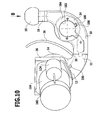
Fig. 5 mit einem Antrieb für die Drehblockiereinrichtung und einem Antrieb für ein Schwenken eines Kugelhalses der Anhängekupplung; - Fig. 8
- eine schematische Ansicht einer Steuereinheit für die Anhängekupplung gemäß
Fig. 1 bis 7 ; - Fig. 9
- eine schematische Darstellung von in dem Kugelhals ausgelösten mechanischen Schwingungen;
- Fig. 10
- eine Darstellung ähnlich
Fig. 4 eines zweiten Ausführungsbeispiels einer erfindungsgemäßen Anhängekupplung; - Fig. 11
- eine schematische Darstellung der Steuerung ähnlich
Fig. 8 des zweiten Ausführungsbeispiels der erfindungsgemäßen Anhängekupplung; - Fig. 12
- eine schematische Darstellung der im Kugelhals auftretenden Schwingungen ähnlich
Fig. 9 bei dem zweiten Ausführungsbeispiel der erfindungsgemäßen Anhängekupplung; - Fig. 13
- eine Darstellung ähnlich
Fig. 4 eines dritten Ausführungsbeispiels einer erfindungsgemäßen Anhängekupplung; - Fig. 14
- eine schematische Darstellung der Steuerung ähnlich
Fig. 8 des dritten Ausführungsbeispiels der erfindungsgemäßen Anhängekupplung und - Fig. 15
- eine Darstellung der mechanischen Schwingungen ähnlich
Fig. 9 bei dem dritten Ausführungsbeispiel der erfindungsgemäßen Anhängekupplung.
- Fig. 1
- a rear view of a motor vehicle with a trailer coupling according to the invention;
- Fig. 2
- an enlarged view of the rear view according to
Fig. 1 with removed bumper unit; - Fig. 3
- a representation similar
Fig. 2 with removed bumper unit and at rest standing trailer hitch; - Fig. 4
- a view of the standing in working position hitch in the direction of arrow X in
Fig. 2 ; - Fig. 5
- a section through a rotation blocking device in the locked state;
- Fig. 6
- a section along line 6-6 in
Fig. 5 ; - Fig. 7
- similar to a cut
Fig. 5 a drive for the rotation blocking device and a drive for pivoting a ball neck of the trailer coupling; - Fig. 8
- a schematic view of a control unit for the trailer coupling according to
Fig. 1 to 7 ; - Fig. 9
- a schematic representation of triggered in the ball neck mechanical vibrations;
- Fig. 10
- a representation similar
Fig. 4 a second embodiment of a trailer coupling according to the invention; - Fig. 11
- a schematic representation of the control similar
Fig. 8 the second embodiment of the trailer coupling according to the invention; - Fig. 12
- a schematic representation of the vibrations occurring in the ball neck similar
Fig. 9 in the second embodiment of the hitch according to the invention; - Fig. 13
- a representation similar
Fig. 4 a third embodiment of a trailer coupling according to the invention; - Fig. 14
- a schematic representation of the control similar
Fig. 8 of the third embodiment of the trailer coupling according to the invention and - Fig. 15
- a representation of the mechanical vibrations similar
Fig. 9 in the third embodiment of the hitch invention.
Ein erstes Ausführungsbeispiel einer erfindungsgemäßen Anhängekupplung für ein Kraftfahrzeug K, dargestellt in
Der Schwenklagerkörper 14 ist durch eine als Ganzes mit 20 bezeichnete und als Schwenklagereinheit ausgebildete Halteeinheit um eine Schwenkachse 22 relativ zu einem fahrzeugfesten Träger 24 schwenkbar gelagert, wobei der Träger 24 vorzugsweise eine die als Schwenklagereinheit 20 ausgebildete Halteeinheit haltende Tragplatte 26 aufweist, welche sich vorzugsweise in einer zur Schwenkachse 22 senkrechten Ebene erstreckt und einen fahrzeugfesten Querträger 28, welcher in bekannter Weise heckseitig einer Fahrzeugkarosserie KA befestigbar ist, und zwar so, dass die Schwenklagereinheit 20 und der Träger 24 auf einer einer Fahrbahnoberfläche F abgewandten Seite einer Unterkante 30 einer Stoßfängereinheit 36 liegen, und durch die Stoßfängereinheit 36 abgedeckt sind (
In der in
Die Schwenklagereinheit 20 umfasst, wie in
Der Führungskörper 40 bildet somit durch seine feste Verbindung mit der Trägerplatte 26 und dem Träger 24 die fahrzeugfeste Drehlagerung für den Schwenklagerkörper 14.The
Zur Fixierung des Schwenklagerkörpers 14 in der Arbeitsstellung A und der Ruhestellung R ist die Schwenklagereinheit 20 mit einer als Ganzes mit 50 bezeichneten Drehblockiereinrichtung versehen, welche einen Betätigungskörper 52, mehrere durch den Betätigungskörper 52 beaufschlagbare Drehblockierkörper 54, beispielsweise Kugeln, welche in Führungsaufnahmen 56 der Führungshülse 44 in einer im wesentlichen radial zur Schwenkachse 22 verlaufenden Führungsrichtung 57 bewegbar geführt sind, sowie sich ausgehend von der Innenfläche 48 des Schwenklagerkörpers 14 in diesen hineinerstreckende erste Aufnahmen 58 und zweite Aufnahmen 60, mit denen die Drehblockierkörper 54 in der Arbeitsstellung A bzw. in der Ruhestellung R in Eingriff bringbar sind, wobei die Aufnahmen 58, 60 in radialer Richtung zur Schwenkachse 22 zunehmend einen geringeren Abstand voneinander aufweisende Wandflächen 59, 61 haben. Im einfachsten Fall verlaufen die Wandflächen 59, 61 als Kegelflächen aufeinanderzu.For fixing the
Umfasst beispielsweise die Drehblockiereinrichtung 50, wie im Zusammenhang mit
Zum geeigneten Bewegen und Positionieren der Drehblockierkörper 54 in der Führungsrichtung 57 ist der Betätigungskörper 52 mit Rückzugsaufnahmen 62 versehen, die im einfachsten Fall durch eine gegenüber dem Führungskörper 40 radial zur Schwenkachse 22 zurückgesetzte zylindrische Fläche 63 des Betätigungskörpers gebildet ist und mit sich an die Rückzugsaufnahmen 62 in axialer Richtung 64 anschließenden Druckflächen 66, welche im einfachsten Fall als eine sich ausgehend von der Zylinderfläche 63 radial zur Schwenkachse 22 konisch erweiternde Konusfläche 67 gebildet sind. Die Drehblockierkörper 54 liegen in ihrer Freilaufstellung oder Lösestellung im Bereich der Rückzugsaufnahmen 62, das heißt der Zylinderfläche 63 des Betätigungskörpers 52 auf und sind damit in radialer Richtung zur Schwenkachse 22 so weit in den Führungskörper 40 hineinbewegt, dass sie nicht mehr über die Außenmantelfläche 46 der Führungshülse 44 überstehen.For suitably moving and positioning the
Mittels der Druckflächen 66 sind die Drehblockierkörper 54 mit zunehmender Verschiebung des Betätigungskörpers 52 in axialer Richtung 64 radial zur Führungshülse 44 so weit nach außen bewegbar, bis sie in einer ersten Drehblockierstellung stehen, in welcher die Drehblockierkörper 54 in ihrer Führungsrichtung 57 so weit nach Außen geschoben sind, dass sie entweder in die Aufnahmen 58 oder die Aufnahmen 60 des Schwenklagerkörpers 14 eingreifen und somit diesen relativ zur Führungshülse 44 festlegen.By means of the pressure surfaces 66, the
Bei dem beschriebenen Ausführungsbeispiel sind der Einfachheit halber die Druckflächen 66 als Konusflächen 67 dargestellt. Anstelle eines Konus kann jedoch jeder sich zunehmen und kontinuierlich radial zur Schwenkachse 22 erweiternde Körper vorgesehen sein, welcher in der Lage ist, beim Verschieben des Betätigungskörpers 52 in der axialen Richtung 64 die Drehblockierkörper 54 in ihren Führungsrichtungen 57 zu bewegen.In the described embodiment, the pressure surfaces 66 are shown as
Um die Drehblockierkörper 54 entweder in ihrer Drehblockierstellung durch Beaufschlagen derselben mit den Druckflächen 66 zu halten oder in der Freilaufstellung auf der Rückzugsaufnahme 62 aufliegen zu lassen, ist der Betätigungskörper 52 in der axialen Richtung 64 parallel zur Schwenkachse 22, insbesondere koaxial zu dieser, verschiebbar, und zwar so, dass entweder die Rückzugsaufnahme 62 dem jeweiligen Drehblockierkörper 54 zugewandt ist und diesem, wie in
Eine Verschiebung des Betätigungskörpers 52 bei auf der jeweiligen Rückzugsaufnahme 62 sitzendem Drehblockierkörper 54 in der Richtung 72 auf die Tragplatte 26 zu bewirkt, dass der jeweilige Drehblockierkörper 54 aus der Rückzugsaufnahme 62 heraus bewegt wird und durch die Druckfläche 66 in seiner Führungsrichtung 57 radial zur Schwenkachse 22 nach außen bewegt wird, somit seine erste Drehblockierstellung erreicht und dabei entweder in die jeweilige erste Aufnahme 58 oder in die jeweilige zweite Aufnahme 60 eintaucht und damit die freie Drehbarkeit des Schwenklagerkörpers 14 unterbindet.A displacement of the
Der Betätigungskörper 52 lässt sich in der Richtung 72 in der axialen Richtung 64 so bewegen, dass auf die Drehblockierkörper 54 zunächst auf Anfangsbereichen 68 der Druckflächen 66 wirken und dann immer weiter radial gegenüber der Schwenkachse 22 außenliegende Bereiche der jeweiligen Druckflächen 66 auf die Drehblockierkörper 54 wirken und diese somit zunehmend, beispielsweise in der Arbeitsstellung A des Kugelhalses 10, in die ersten Aufnahmen 58a, 58b und 58c hineindrücken, wie dies in
In dieser Drehblockierstellung der Drehblockierkörper 54 steht der Betätigungskörper 52 in seiner aktiven Stellung so, dass die Betätigungskörper 52, wie in
Eine spielfreie Verriegelung des Schwenklagerkörpers 14 durch die in ihrer Drehblockierstellung stehenden Drehblockierkörper 54 lässt sich besonders günstig dann erreichen, wenn der Drehblockierkörper 54 und die Aufnahmen 58 und 60 so gestaltet sind, dass bei zunehmendem Eintauchen eines der Drehblockierkörper 54 in eine der Aufnahmen 58 oder 60 und Anliegen der Drehblockierkörper 54 an einer Seite der Aufnahmen 58 und 60 jeder der Drehblockierkörper 54 mit der wechselwirkenden Aufnahme 58 oder 60 eine Verdrehung des Schwenklagerkörpers 14 bewirkt, wobei insgesamt der Satz von Drehblockierkörpern 54a bis 54c zur spielfreien Fixierung des Schwenklagerkörpers 14 mit in entgegengesetzten Richtungen wirkenden Drehmomenten 90, 92 auf die Gesamtheit der Aufnahmen 58 oder 60 einwirkt.A play-free locking of the
Um dem Betätigungskörper 52 die Möglichkeit zu eröffnen, in der Drehblockierstellung jeweils jeden der drei Drehblockierkörper 54 optimal zu beaufschlagen, ist vorgesehen, dass in der aktiven Stellung eine Zentrierung des Betätigungskörpers 52 entsprechend der Lage der Drehblockierkörper 54 erfolgt, so dass sich der Betätigungskörper 52 relativ zur Schwenkachse 22 bewegen und entsprechend der durch Fertigungstoleranzen bedingten Lage der Drehblockierkörper 54 sich innerhalb des Führungskörpers 40 selbstzentrieren kann, wobei die Selbstzentrierung des Betätigungskörpers 52 geringfügig von einer koaxialen Anordnung zur geometrischen Schwenkachse 22 abweichen kann.In order to open up the possibility to the
Aufgrund der Selbstzentrierung wirken die Drehblockierkörper 54a, 54b und 54c in der jeweiligen Führungsrichtung 57a, 57b und 57c mit ungefähr gleich großen Kräften Ka, Kb und Kc auf die Aufnahmen 58a, 58b und 58c oder 60a, 60b und 60c, so dass auch die auf den Betätigungskörper 52 wirkenden Reaktionskräfte RKa, RKb und RKc ungefähr gleich groß sind.Due to the self-centering the
Bei dem dargestellten Ausführungsbeispiel der erfindungsgemäßen Lösung sind die Drehblockierkörper 54 in den Führungsaufnahmen 56 in gleichen Winkelabständen um die Schwenkachse 22 herum angeordnet, so dass die durch die Selbstzentrierung ungefähr gleich großen Reaktionskräfte RKa, RKb, RKc auf einen der Drehblockierkörper 54a, 54b, 54c sich zu gleichen Teilen auf die anderen Drehblockierkörper 54b und 54c, 54a und 54c sowie 54a und 54b auswirken und sich somit insgesamt aufheben, so dass der Betätigungskörper 52 im Kräftegleichgewicht steht und keine zusätzliche Abstützung benötigt. Im dargestellten Ausführungsbeispiel sind die Drehblockierkörper 54, wie beispielsweise in der
Zum Bewegen des Betätigungskörpers 52 in der axialen Richtung 64 ist ein Drehblockierantrieb 100 vorgesehen, der eine als Ganzes mit 102 bezeichnete Gewindespindel aufweist, auf welcher der Betätigungskörper 52 sitzt. Die Gewindespindel 102 ist an der Tragplatte 26 beispielsweise über ein Axial-/Radiallager 103 in der axialen Richtung 64 unverschieblich gelagert.For moving the operating
Diese Gewindespindel 102 greift mit einem Außengewinde 104 in ein Innengewinde 106 des Betätigungskörpers 54 ein, der somit gleichzeitig eine Spindelmutter zu der Gewindespindel 102 darstellt. Es besteht die Möglichkeit, die Selbstzentrierung des Betätigungskörpers 52 durch ausreichend großes Spiel zwischen dem Außengewinde 104 und dem Innengewinde 106 zu erreichen.This threaded
Durch Drehen der Gewindespindel 102 lässt sich somit der Betätigungskörper 52 in der axialen Richtung 64 verschieben.By rotating the threaded
Vorzugsweise ist das Axial-/Radiallager 103 so ausgebildet, dass es die Gewindespindel 102 nicht exakt koaxial zur Schwenkachse 22 führt, sondern eine Ausweichbewegung der Gewindespindel 102 quer zur Schwenkachse 22 zulässt, um die bereits beschriebene Selbstzentrierung des Betätigungskörpers 52 in der Führungshülse 44 zu ermöglichen.Preferably, the axial /
Zum Antreiben der Gewindespindel 102 umfasst der Drehblockierantrieb 100 ein auf einer dem Betätigungskörper 52 gegenüberliegenden Seite der Tragplatte 26 sitzendes Antriebsrad 110, welches mit einem Antriebsrad 112 eines elektrischen Antriebsmotors 114 des Drehblockierantriebs 100 in Eingriff steht, wobei der elektrische Antriebsmotor 114 beispielsweise als Elektromotor mit einem Untersetzungsgetriebe ausgebildet ist.To drive the threaded
Der elektrische Antriebsmotor 114 des Drehblockierantriebs 100 ist über eine in
Ein Verschwenken des Kugelhalses 10 kann in der Freigabestellung der Drehblockiereinrichtung 50 manuell erfolgen.A pivoting of the
Bei dem dargestellten ersten Ausführungsbeispiel ist zum Verschwenken des Kugelhalses 10 der Schwenklagerkörper 14 beispielsweise mit einer externen Verzahnung 132 versehen, in welche ein Antriebsrad 134 eines mit einem elektrischen Antriebsmotor 136 versehenen Schwenkantriebs 140 eingreift.In the illustrated first embodiment, for pivoting the
Der Schwenkantrieb 140 ist - wie in
Damit ist die Schwenksteuerung 150 in der Lage, bei Erreichen einer Endstellung, die zum Anstieg des Stroms durch den Elektromotor 136 führt, oder in einem Gefahrenfall, in dem die Bewegung des Kugelhalses 10 durch ein Hindernis blockiert ist, die Bestromung des elektrischen Antriebsmotors 136 durch die Leistungsstufe 152 zu beenden oder zu invertieren.Thus, the
Beispielsweise sind Funktionen einer derartigen Schwenksteuerung 150 in der europäischen Patentanmeldung
Die Drehblockiersteuerung 120 und die Schwenksteuerung 150 sind Teil einer als Ganzes mit 160 bezeichneten Steuerung der Anhängekupplung, die, wie in
Wie in
Der Grund für ein derartiges Verspannen des Drehblockierantriebs 50 in der Drehblockierstellung ist der, dass sich bereits ein geringes Spiel zwischen der jeweiligen Außenfläche 84 des jeweiligen Drehblockierkörpers 54 sowie den Seiten 88 oder 89 der Aufnahmen 58 oder den Seiten 86 der Führungsaufnahmen 56 dazu führt, dass Materialdeformationen auftreten, die das Material so weit deformieren, dass sich das Spiel vergrößert.The reason for such distortion of the
Liegt jedoch zwischen der Außenfläche 84 und den Seiten 88 oder 89 und den Seiten 86 kein Spiel vor, so wird die Materialdeformation vermieden und somit vermieden, dass sich das Spiel vergrößert und sich im Laufe der Zeit ein Zustand der Drehblockiereinrichtung 50 einstellt, in welchem diese keine spielfreie Fixierung zwischen dem Schwenklagerkörper 14 und dem Führungskörper 40 mehr zulässt.However, if there is no clearance between the outer surface 84 and the sides 88 or 89 and the sides 86, the material deformation is avoided, thus avoiding that the play increases and over time a state of the
Um diesen Verspannzustand der Drehblockiereinrichtung 50 zu erreichen, wird der elektrische Antriebsmotor 114 des Drehblockierantriebs 100 durch die Endstufe 122 auch bei Erreichen der Drehblockierstellung so lange betrieben, bis ein ausreichend großes Drehmoment am elektrischen Antriebsmotor 114 auftritt, das durch den Stromsensor 124 erkannt werden kann und bei welchem die Drehblockiersteuerung 120 die Endstufe 122 abschaltet.In order to achieve this Verspannzustand the
Die Verspannsteuerung 170 umfasst einen Prozessor 171 und eine Endstufe 172, die in einem Verspannbetriebsmodus allerdings keinen Dauerstrom zum Betreiben des elektrischen Antriebsmotors 140 erzeugt, sondern einzelne aufeinanderfolgende Strompulse SP, welche durch Pulspausen PP voneinander getrennt sind.The
Die Strompulse SP ergeben eine Pulsfolge PF, die allerdings in Abhängigkeit von einer Verspannung beim Übergang in den Verspannbetriebsmodus von unterschiedlicher Dauer sein kann.The current pulses SP result in a pulse sequence PF, which, however, can be of different duration as a function of a distortion during the transition to the clamping operation mode.
Um eine Belastung B der Kupplungskugel 18 durch ein an dieser angreifendes Objekt zu erfassen, welche im Fall eines Anhängers, der mit einer Stützlast auf die Kupplungskugel 18 wirkt, in erster Näherung in der Arbeitsstellung des Kugelhalses 10 ungefähr vertikal ausgerichtet ist, ist, wie in
Vorzugsweise ist der Sensor 180 nahe einer Aufnahme 182 für eine elektrische Kontakteinheit vorgesehen, wobei die Aufnahme 182 im Kugelhals 10 beispielsweise als Durchbruch ausgebildet ist, welcher von einem Versteifungsring 184 umgeben ist. Der Versteifungsring 184 ist dabei beispielsweise mit einer Tasche 186 versehen, in welcher der Sensor 180 sitzt.Preferably, the
Wie in
Vorzugsweise ist der Sensor 180 richtungsselektiv, so dass dieser beispielsweise in der Lage ist, in einer ersten, parallel zur Fahrtrichtung verlaufenden Richtung in einer zweiten, quer zur Fahrtrichtung und insbesondere ungefähr parallel zum Querträger 28 verlaufenden Richtung und in einer dritten, insbesondere ungefähr quer zur Fahrtrichtung verlaufenden Richtung gerichtete Beschleunigungen voneinander getrennt zu erfassen, auszuwerten und gegebenenfalls abzuspeichern.Preferably, the
Die Erfassung der Belastung B der Kupplungskugel 18 erfolgt über eine Auswertung eines Verhaltens des Kugelhalses 10 im Falle von durch eine Erregung im Kugelhals 10 erzeugten mechanischen Schwingungen, wobei die mechanischen Schwingungen im Kugelhals 10 eine Frequenz f und eine Amplitude A aufweisen, die bei Nichtbelastung der Kupplungskugel 18 und des Kugelhalses 10, wie in
Erfolgt jedoch eine Belastung der Kupplungskugel 18 und des Kugelhalses 10, so weisen die mechanischen Schwingungen Amplitudenwerte Ab auf, die, wie ebenfalls in
Dabei kann, wie beispielsweise exemplarisch in
Die Belastung des Kugelhalses 18 muss nicht zwingend von der Stützlast herrühren, sondern kann auch nur durch eine Bedämpfung des Kugelhalses bei angehängtem Anhänger entstehen, ohne dass die Stützlast in vertikaler Richtung auf die Kupplungskugel 18 wirkt.The load on the
Die Auswerteeinheit 190 ist nun in der Lage, entweder bei einer konstanten Erregung der mechanischen Schwingung im Kugelhals 10 die Amplitude A zu erfassen und mit dem Amplitudenwert Au im unbelasteten Zustand zu vergleichen und daraus auf eine Belastung B der Kupplungskugel 18 und des Kugelhalses 10 zu schließen oder in der Lage, bei Abklingen der mechanischen Schwingung das Abklingverhalten gemäß der Abklingkurve AK in Relation zur Abklingkurve AKu bei unbelasteter Kupplungskugel 18 und unbelastetem Kugelhals 10 auszuwerten.The
Es besteht aber auch die Möglichkeit, dass die Auswerteeinheit 190 sowohl die Amplitude A als auch das Abklingverhalten AK auswertet und aus diesen Größen die Belastung B, die auf die Kupplungskugel 18 und den Kugelhals 10 einwirkt, ermittelt. Hierzu ist der Auswerteeinheit 190 ein Referenzwertspeicher 192 zugeordnet, welcher Referenzwerte Entweder für die Amplituden A und/oder die Abklingkurven AK und/oder auch die Frequenz f der mechanischen Schwingungen aufweist, so dass anhand dieser Referenzwerte ein Rückschluss auf die Belastung B möglich ist. Hierzu sind die Referenzwerte im Referenzwertspeicher 192 für das jeweilige System umfassend den Kugelhals 10, die Kupplungskugel 18 sowie die Halteeinheit 20 im Zuge eines Eichvorgangs zu erfassen.However, there is also the possibility that the
Mit der Auswerteeinheit 190 besteht somit die Möglichkeit, zu erfassen, ob überhaupt eine Belastung B an der Kupplungskugel 18 und im Kugelhals 10 vorliegt, um dadurch beispielsweise die Präsenz eines Anhängers an der Anhängekupplung zu erkennen oder es besteht die Möglichkeit, zu ermitteln, wie groß die Belastung der Kupplungskugel 18 und des Kugelhalses 10 ist.Thus, with the
Eine derartige Ermittlung kann zur Ermittlung einer Stützlast des Kugelhalses 10 herangezogen werden, so dass nach dem Anhängen eines Anhängers eine Prüfung dahingehend möglich ist, ob die Stützlast des Anhängers, die auf die Kupplungskugel 18 und den Kugelhals 10 wirkt, eine Belastung B darstellt, die im Bereich der vorgesehenen Stützlast liegt oder ob die Belastung B so groß ist, dass die für die Anhängekupplung vorgesehene zulässige Stützlast überschritten ist.Such a determination can be used to determine a support load of the
Für eine derartige quantitative Erfassung der Stützlast, die auf die Kupplungskugel 18 und den Kugelhals 10 wirkt, sind mehrere Referenzwerte im Referenzwertspeicher 192 vorzusehen, die bei der Auswertung durch die Auswerteeinheit 190 herangezogen werden.For such a quantitative detection of the vertical load, which acts on the
Die Erregung der mechanischen Schwingungen in dem Kugelhals 10 kann in unterschiedlichster Art und Weise erfolgen.The excitation of the mechanical vibrations in the
Bei dem in
Beispielsweise wird der Vibrationsgenerator 200 bei Schallfrequenz f betrieben, die im hörbaren Bereich liegen können, vorzugsweise jedoch höher sind als 500 Hz, noch besser höher als 800 Hz und noch besser höher als 1 kHz, um Störungen durch Umgebungseinflüsse zu reduzieren.For example, the
Zweckmäßigerweise ist vorgesehen, dass die Frequenzen niedriger sind als 15 kHz.Appropriately, it is provided that the frequencies are lower than 15 kHz.
Der Vibrationsgenerator 200 kann dabei im Dauerbetrieb arbeiten. Eine verbesserte Störunterdrückung ist dann möglich, wenn der Vibrationsgenerator 200 gepulst arbeitet und dabei insbesondere eine mit den Pulsen synchronisierte Signalauswertung, beispielsweise in Lock-in Technik erfolgt.The
Aus diesem Grund ist bei dem ersten Ausführungsbeispiel, wie in
So sind beispielsweise bei größerer Belastung B der Kupplungskugel 18 und des Kugelhalses 10 die Amplitudenwerte Ab und somit auch die Maximalwerte Maxb niedriger als bei weniger großer Belastung B.For example, at greater load B of the
Ferner kann nach Beendigung der Aktivierung des Vibrationsgenerators 200 noch eine Auswertung des Abklingens der mechanischen Schwingung durch Auswertung der Abklingkurven AK erfolgen und somit bei belasteter Kupplungskugel 18 und belastetem Kugelhals 10 eine Auswertung der Amplituden Ab, und der Abklingkurve AKb, wie ebenfalls in
Durch Vergleich der Amplitudenwerte Ab mit den im Referenzwertspeicher 192 abgelegten Referenzwerten für die Amplituden A und/oder Vergleich der Abklingkurve AKb mit im Referenzwertspeicher 192 abgelegten Referenzwerten für die Abklingkurve AK lässt sich dann die Belastung B der Kupplungskugel 18 und des Kugelhalses 10 ermitteln. Wie in
Die Maximalwerte Maxb der Amplitudenwerte Ab und/oder die Abklingkurve AKb können nicht nur von der Stützlast abhängig sein, sondern auf von der Masse des Anhängers, so dass diese als weiterer Einflussfaktor von der Auswerteeinheit 190 zu berücksichtigen ist. Im einfachsten Fall erfolgt eine Auswahl der Referenzwerte in Abhängigkeit von der Masse des Anhängers.The maximum values Max b of the amplitude values A b and / or the decay curve AK b may depend not only on the vertical load, but on the mass of the trailer so that it is to be considered as a further influencing factor by the
Eine verbesserte Auswertung, insbesondere zum Reduzieren von Störungen, sieht vor, die auf den Sensor 180 einwirkenden Beschleunigungen richtungsselektiv zu erfassen und auszuwerten.An improved evaluation, in particular for reducing disturbances, provides for detecting and evaluating the accelerations acting on the
Dabei können außerdem zu geringe Beschleunigungswerte ignoriert werden. Die für die Auswerteeinheit 190 vorgesehenen Beschleunigungswerte liegen unterhalb von 100 m/sec2, d.h. 10g.In addition, too low acceleration values can be ignored. The acceleration values provided for the
Vorzugsweise sind als Voraussetzung für die Erfassung der Messwerte Mindestbeschleunigungen von 0,5 m/sec2 vorgesehen, wenn es darum geht, diese als Messwerte auszuwerten.As a prerequisite for acquiring the measured values, minimum accelerations of 0.5 m / sec 2 are preferably provided when it comes to evaluating them as measured values.
Werden die Beschleunigungen richtungsselektiv erfasst, so erfolgt auch ein Vergleich mit richtungsselektiven Referenzwerten, wodurch die Möglichkeit besteht, den Einfluss von Störquellen die Beschleunigungen erzeugen, zu reduzieren oder zu unterdrücken.If the accelerations are detected in a directionally selective manner, a comparison with direction-selective reference values also takes place, with the result that it is possible to generate, reduce or suppress the influence of interference sources on the accelerations.
Alternativ zum Vorsehen des Vibrationsgenerators 200 ist bei einem zweiten Ausführungsbeispiel, dargestellt in den
Die dabei im Kugelhals 10 erzeugten mechanischen Schwingungen sind hinsichtlich ihrer Frequenz f und Amplitude A durch die Form des Kugelhalses 10 und der Kupplungskugel 18 sowie die Materialparameter derselben mitbestimmt, so dass insbesondere sich die Frequenz f der mechanischen Schwingungen nach dem einmaligen Impuls entsprechend den vorgegebenen Systemparametern einstellt.The mechanical vibrations generated in the
Die Frequenzen f liegen beispielsweise in denselben Wertebereichen wie beim ersten Ausführungsbeispiel dargelegt.The frequencies f are, for example, in the same value ranges as set forth in the first embodiment.
Ferner liegt in diesem Fall auch kein Zeitraum t1 mit einer konstanten Erregung der mechanischen Schwingungen vor, sondern es wird unmittelbar nach dem Impuls sich eine mechanische Schwingung einstellen, die während des Zeitraums t2 abklingt. Die Auswerteeinheit 190 erfasst daher die Abklingkurven AK der Amplituden A und wertet dieses Abklingverhalten in Abhängigkeit von im Referenzwertspeicher 192 gespeicherten Referenzwerten für die Abklingkurven der mechanischen Schwingung nach Setzen des mechanischen Impulses aus.Furthermore, in this case there is no time interval t 1 with a constant excitation of the mechanical vibrations, but immediately after the pulse a mechanical oscillation will occur which decays during the period t 2 . The
Darüber hinaus besteht noch die Möglichkeit, auch die Frequenz f der sich einstellenden mechanischen Schwingungen auszuwerten, die bei diesem Ausführungsbeispiel bei nicht vorliegender Belastung B an der Kupplungskugel 18 und im Kugelhals 10 anders sein kann als bei an der Kupplungskugel 18 und im Kugelhals 10 vorliegender Belastung B. Bei diesem Ausführungsbeispiel besteht somit die Möglichkeit, dass abhängig von der Belastung B der Kupplungskugel 18 und des Kugelhalses 10 sowohl das Abklingverhalten AK als auch die Frequenz f der mechanischen Schwingung sich ändern, so dass die Auswerteeinheit 190 beide Größen durch Vergleich mit im Referenzwertspeicher 192 abgelegten Referenzwerten auswerten kann.In addition, there is also the possibility to evaluate the frequency f of the adjusting mechanical vibrations, which may be different in this embodiment in the absence of load B on the
Bei diesem Ausführungsbeispiel erfolgt ferner die Erfassung der Messwerte des Sensors 180 in zeitlicher Korrelation zur Erzeugung des mechanischen Impulses durch den Impulsgenerator 230, so dass während der Abgabe des mechanischen Impulses an den Kugelhals 10 keine Messung erfolgt, jedoch kurze Zeit nach Beendigung der Erzeugung des mechanischen Impulses die Aufnahme der Messwerte des Sensors 180 mittels der Messwerterfassung und die Auswertung derselben beginnen kann.In this embodiment, further, the detection of the measured values of the
Bei einer dritten Ausführungsform einer erfindungsgemäßen Anhängekupplung, dargestellt in den
Das heißt, dass auch bei diesem Ausführungsbeispiel die Auswerteeinheit 190 einerseits das Abklingverhalten AK der mechanischen Schwingung und andererseits gegebenenfalls auch eine Änderung der Frequenz f der mechanischen Schwingung auswertet, die davon abhängig sind, ob und wie groß die Belastung B, die auf die Kupplungskugel 18 und den Kugelhals 10 wirkt, ist.This means that in this embodiment too, the
Das Spektrum der Frequenzen f der mechanischen Schwingungen liegt auch bei diesem Ausführungsbeispiel beispielsweise schwerpunktmäßig in den zum ersten Ausführungsbeispiel genannten Wertebereichen.The spectrum of the frequencies f of the mechanical vibrations is also in this embodiment, for example, mainly in the value ranges mentioned for the first embodiment.
Bei allen vorstehend beschriebenen Ausführungsbeispielen erfolgt die Erfassung der Belastung B der Kupplungskugel 18 und des Kugelhalses 10 beispielsweise bei stehendem Fahrzeug und in einem Zeitraum, der zwischen einem Anhängen des Anhängers und einem Fahren des Fahrzeugs mit angehängtem Anhänger schneller als Schrittgeschwindigkeit liegt.In all the embodiments described above, the detection of the load B of the
Die Tatsache, dass an die Anhängekupplung ein Anhänger angehängt wurde, lässt sich beispielsweise dadurch ermitteln, dass eine Verbindung einer zwischen einem Bordnetz 260 des Kraftfahrzeugs und dem elektrischen Versorgungsnetz 270 des Anhängers erfolgt, beispielsweise dadurch, dass eine Steckverbindung zwischen einem der Anhängekupplung zugeordneten Kontakteinheit 262 des Kraftfahrzeugs und einem Kontaktelement 272 des Anhängers, beispielsweise üblicherweise einem am Anhänger vorgesehenen Stecker, erfolgt.The fact that a trailer has been attached to the towing hitch can be determined, for example, by connecting one between an on-
Die Herstellung dieser Verbindung zwischen dem Bordnetz 260 des Kraftfahrzeugs und dem Versorgungsnetz 270 des Anhängers wird von einem Detektor 264 und einer zugeordneten Detektoreinheit 266 erkannt und aktiviert die Überwachungssteuerung 220, so dass diese die Belastung B der Kupplungskugel 18 und des Kugelhalses 10 erfasst und je nach dem von der Auswerteeinheit 190 ermittelten Ergebnis eine am Kraftfahrzeug vorgesehene Anzeige ansteuert, die anzeigt, ob eine Belastung der Kupplungskugel 18 und des Kugelhalses 10 vorliegt und/oder ob die Belastung im Bereich der vorgesehenen Stützlast liegt oder ob die vorgesehene Stützlast der Anhängekupplung überschritten wurde.The production of this connection between the on-
Bei einer weiteren Ausführungsform der erfindungsgemäßen Anhängekupplung kann ergänzend der als Beschleunigungssensor arbeitende Sensor 180 auch dazu eingesetzt werden, jede Art von Beschleunigungen im Kugelhals 10 zu erfassen, und zwar auch Beschleunigungen, die in keinem Zusammenhang mit einer definierten Erregung von Schwingungen im Kugelhals 10 sind.In a further embodiment of the towing hitch according to the invention, the
Derartige Beschleunigungen können beispielsweise beim Fahrbetrieb auftretende Beschleunigungen sein, die auch im Kugelhals 10 feststellbar sind.Such accelerations may be, for example, accelerations occurring during driving, which are also detectable in the
In diesem Fall werden im normalen Fahrbetrieb auftretende Beschleunigungen unterdrückt und nur Beschleunigungswerte erfasst, die größer sind als die bei einer Vollbremsung, beispielsweise 50 m/sec2 oder 5g, wobei diese Beschleunigungen dadurch auftreten, dass ein Aufprall auf den Kugelhals 10 beispielsweise im Zusammenhang mit einem Unfall erfolgt.In this case, occurring during normal driving accelerations are suppressed and detected only acceleration values that are greater than those at a full braking, for example 50 m / sec 2 or 5g, these accelerations occur in that an impact on the
In diesem Fall arbeitet eine Beschleunigungserfassungseinheit 280 unabhängig davon, ob ein Anhänger an der Anhängekupplung angehängt ist oder nicht, so dass diese über die Messwerterfassung 188 des Sensors 180 die Beschleunigungswerte erfasst, die über einem in einem Referenzwertspeicher 282 abgelegten Minimalwert der Beschleunigung liegen, und diese Messwerte in einem eigenen Speicher 284 speichert und/oder einem Zentralcomputer Z des Kraftfahrzeugs übermittelt, die in der Lage sind, diese Messwerte entweder mit zeitlicher Korrelation oder gegebenenfalls auch ohne zeitliche Korrelation abzuspeichern, so dass sich später aus dem Speicher 284 oder dem Zentralcomputer Z des Kraftfahrzeugs auslesen lässt, ob die Anhängekupplung, insbesondere der Kugelhals 10, in einen Verkehrsunfall verwickelt waren oder nicht.In this case, regardless of whether or not a trailer is attached to the trailer hitch, an
Alternativ oder ergänzend dazu lässt sich der Sensor 180 mit der Beschleunigungserfassungseinheit 280 aber auch dazu einsetzen, ein abgestelltes und verschlossenes Fahrzeug auch dahingehend zu überwachen, ob das Fahrzeug im abgestellten und abgeschlossenen Zustand Beschleunigungen unterworfen wurde. In diesem Fall kann die Bandbreite der erfassten Beschleunigungen größer gewählt werden, so dass auch Beschleunigungswerte, die niedriger sind als die bei einer Vollbremsung erfasst werden. Die Bandbreite der erfassten Beschleunigungswerte kann insbesondere bis zu Beschleunigungswerten reichen, die bei einem Aufladen des stehenden Fahrzeugs auf einen Transporter auftreten.Alternatively or additionally, however, the
Die erfassten Beschleunigungen können beispielsweise dadurch entstehen, dass das Fahrzeug im abgestellten und abgeschlossenen Zustand von einem weiteren Fahrzeug angefahren und somit in einen Unfall verwickelt wurde oder auch darin, dass es gestohlen wird.The detected accelerations may arise, for example, when the vehicle was parked and locked up by another vehicle and thus involved in an accident or even that it is being stolen.
Erkennt in diesen Fällen die Ablaufsteuerung 222 aufgrund einer Meldung der Beschleunigungserfassungseinheit 280 dass eine ungewöhnlich große Beschleunigung an dem Kugelhals 10 festgestellt wird, so kann die Ablaufsteuerung 222 über eine Sendeeinheit 300 veranlassen, dass ein eine derartige ungewöhnliche Beschleunigung übermittelndes Signal S beispielsweise über das Mobilfunknetz an ein vorab definiertes Empfangsgerät, beispielsweise ein Mobiltelefon, gesendet wird, so dass in diesem Fall der Fahrer in der Lage ist, zu erkennen, dass an seinem Fahrzeug ein unüblicher Beschleunigungszustand aufgetreten ist.If, in these cases, the
Die Einrichtung umfassend den Beschleunigungssensor 180, die Messwerterfassung 188 und die Beschleunigungserfassungseinheit 280 mit dem Referenzwertspeicher 282 und dem Speicher 284 kann aber auch unabhängig von einer Anhängekupplung dem Zentralcomputer Z eines Kraftfahrzeugs zugeordnet werden, der dann als Ablaufsteuerung wirkt und dieThe device comprising the
Sendeeinheit 300 ansteuert, so dass alle vorstehend beschriebenen Funktionen bei der Erfassung von Beschleunigungen des Fahrzeugs auch unabhängig von einer Anhängerkupplung realisierbar sind.
Claims (15)
eine fahrzeugfest angeordnete Halteeinheit (20),
einen Kugelhals (10) welcher in einer Arbeitsstellung (A) im Bereich eines ersten Endes (12) mit der Halteeinheit (20) verbunden ist, und eine Kupplungskugel (18), welche an einem zweiten Ende (16) des Kugelhalses (10) angeordnet ist,
dadurch gekennzeichnet, dass eine Beschleunigungserfassungseinheit (280) mittels eines Sensors (180) auf den Kugelhals (10) einwirkende fremdausgelöste Beschleunigungen erfasst.Includes trailer hitch for motor vehicles
a vehicle-mounted holding unit (20),
a ball neck (10) which is connected in a working position (A) in the region of a first end (12) with the holding unit (20), and a coupling ball (18) arranged at a second end (16) of the ball neck (10) is
characterized in that an acceleration detection unit (280) detects externally triggered accelerations acting on the ball neck (10) by means of a sensor (180).
Applications Claiming Priority (2)
| Application Number | Priority Date | Filing Date | Title |
|---|---|---|---|
| DE102009046179A DE102009046179A1 (en) | 2009-10-29 | 2009-10-29 | Towing |
| EP10188249.6A EP2316669B2 (en) | 2009-10-29 | 2010-10-20 | Tow bar |
Related Parent Applications (2)
| Application Number | Title | Priority Date | Filing Date |
|---|---|---|---|
| EP10188249.6A Division EP2316669B2 (en) | 2009-10-29 | 2010-10-20 | Tow bar |
| EP10188249.6A Division-Into EP2316669B2 (en) | 2009-10-29 | 2010-10-20 | Tow bar |
Publications (3)
| Publication Number | Publication Date |
|---|---|
| EP2815900A1 true EP2815900A1 (en) | 2014-12-24 |
| EP2815900B1 EP2815900B1 (en) | 2016-04-27 |
| EP2815900B2 EP2815900B2 (en) | 2021-07-28 |
Family
ID=43480856
Family Applications (2)
| Application Number | Title | Priority Date | Filing Date |
|---|---|---|---|
| EP14176932.3A Active EP2815900B2 (en) | 2009-10-29 | 2010-10-20 | Trailer coupling |
| EP10188249.6A Active EP2316669B2 (en) | 2009-10-29 | 2010-10-20 | Tow bar |
Family Applications After (1)
| Application Number | Title | Priority Date | Filing Date |
|---|---|---|---|
| EP10188249.6A Active EP2316669B2 (en) | 2009-10-29 | 2010-10-20 | Tow bar |
Country Status (2)
| Country | Link |
|---|---|
| EP (2) | EP2815900B2 (en) |
| DE (1) | DE102009046179A1 (en) |
Cited By (1)
| Publication number | Priority date | Publication date | Assignee | Title |
|---|---|---|---|---|
| DE102015204900A1 (en) * | 2015-03-18 | 2016-09-22 | Zf Friedrichshafen Ag | Ball pivot module and method for operating a ball pivot module |
Families Citing this family (13)
| Publication number | Priority date | Publication date | Assignee | Title |
|---|---|---|---|---|
| DE102009046179A1 (en) | 2009-10-29 | 2011-05-05 | Scambia Industrial Developments Aktiengesellschaft | Towing |
| EP3357717B2 (en) | 2011-11-03 | 2023-11-22 | WESTFALIA - Automotive GmbH | Draw bar with an evaluation device |
| DE102013007726A1 (en) * | 2013-05-07 | 2014-11-13 | Westfalia-Automotive Gmbh | Trailer coupling with an evaluation device |
| DE102014008077A1 (en) * | 2014-05-30 | 2015-12-03 | Westfalia-Automotive Gmbh | Trailer coupling with a clutch usage sensor |
| US10704972B2 (en) | 2016-02-23 | 2020-07-07 | Brink Towing Systems B.V. | Method for measuring a load on a towing hook and a towing hook arrangement |
| EP3379222B1 (en) | 2017-03-22 | 2020-12-30 | Methode Electronics Malta Ltd. | Magnetoelastic based sensor assembly |
| US11135882B2 (en) | 2018-02-27 | 2021-10-05 | Methode Electronics, Inc. | Towing systems and methods using magnetic field sensing |
| US11491832B2 (en) | 2018-02-27 | 2022-11-08 | Methode Electronics, Inc. | Towing systems and methods using magnetic field sensing |
| DE18907724T1 (en) | 2018-02-27 | 2021-03-25 | Methode Electronics, Inc. | Towing systems and methods using magnetic field measurement |
| US11084342B2 (en) | 2018-02-27 | 2021-08-10 | Methode Electronics, Inc. | Towing systems and methods using magnetic field sensing |
| US11221262B2 (en) | 2018-02-27 | 2022-01-11 | Methode Electronics, Inc. | Towing systems and methods using magnetic field sensing |
| WO2021219209A1 (en) * | 2020-04-29 | 2021-11-04 | HELLA GmbH & Co. KGaA | Trailer hitch with a swivellable hitch hook and a motor for swivelling the hitch hook |
| DE102021121092A1 (en) * | 2021-08-13 | 2023-02-16 | ACPS Automotive GmbH | hitch |
Citations (4)
| Publication number | Priority date | Publication date | Assignee | Title |
|---|---|---|---|---|
| US6053521A (en) * | 1998-04-16 | 2000-04-25 | Schertler; Stephen James | Load sensing trailer ball-hitch drawbar |
| EP1002671A2 (en) | 1996-04-01 | 2000-05-24 | ORIS FAHRZEUGTEILE HANS RIEHLE GmbH | Trailer coupling |
| EP1160105A2 (en) * | 2000-06-02 | 2001-12-05 | ORIS FAHRZEUGTEILE HANS RIEHLE GmbH | Trailer coupling |
| EP2233326A1 (en) * | 2009-03-25 | 2010-09-29 | SCAMBIA Industrial Developments Aktiengesellschaft | Tow bar |
Family Cites Families (20)
| Publication number | Priority date | Publication date | Assignee | Title |
|---|---|---|---|---|
| DE3617426C1 (en) | 1986-05-23 | 1987-09-10 | Audi Ag | Hitching (coupling) device |
| DE3703655A1 (en) * | 1987-02-06 | 1988-08-18 | Industrieanlagen Betriebsges | Acoustic damping detector for nondestructive material tests |
| DE3818126A1 (en) * | 1988-05-27 | 1989-11-30 | Pfister Gmbh | Force measuring device |
| DE19612962A1 (en) * | 1996-04-01 | 1997-10-02 | Oris Fahrzeugteile Riehle H | Trailer coupling |
| GB9907523D0 (en) | 1999-04-01 | 1999-05-26 | Evans Kenneth S | Tow coupling sensor |
| GB2353340B (en) | 1999-08-20 | 2003-11-05 | Vincent Roy Garvey | Trailer safety |
| US6636791B2 (en) | 2001-01-05 | 2003-10-21 | Calsonic Kansei Corporation | Collision record apparatus, collision state estimation method, and record medium |
| DE10127567A1 (en) | 2001-06-06 | 2002-12-12 | Bpw Bergische Achsen Kg | Method for determining the weight load of an air-tired vehicle axle that is sprung against the vehicle body |
| JP4685289B2 (en) | 2001-09-03 | 2011-05-18 | 本田技研工業株式会社 | Collision detection system |
| WO2004012051A2 (en) * | 2002-07-26 | 2004-02-05 | Zielinski Reuben Q | Computer controlled positioning device |
| NL1024538C1 (en) | 2003-10-14 | 2005-04-15 | Sybe Sijbesma | Ball loading and trailer mass measurement is effected with aid of suitable towing hook or tow bar and involves application of elastic strips on hook or tow bar and an acceleration sensor measuring acceleration in two directions |
| US7190258B2 (en) | 2004-10-21 | 2007-03-13 | Richard Lee | Alarm for a livestock trailer and method of use thereof |
| US7191089B2 (en) | 2004-12-01 | 2007-03-13 | Freescale Semiconductor, Inc. | System and method for fall detection |
| DE102005026188A1 (en) | 2005-06-06 | 2006-12-07 | Daimlerchrysler Ag | Control method for an accident prevention device in a vehicle |
| KR101281273B1 (en) * | 2005-07-06 | 2013-07-03 | 내셔날 리서치 카운실 오브 캐나다 | Method and system for determining material properties using ultrasonic attenuation |
| US20070194557A1 (en) | 2006-01-27 | 2007-08-23 | Lockheed Martin, Corporation | Intelligent tow bar |
| DE102006012110A1 (en) | 2006-02-23 | 2007-08-30 | Benteler Automobiltechnik Gmbh | landing gear assembly |
| WO2008141695A2 (en) | 2007-03-30 | 2008-11-27 | Uwe Rehwald | Arrangement and method for determining and/or evaluating bodies and/or structures moved by vibrations and/or having a drive |
| DE102007039699C5 (en) | 2007-08-22 | 2022-03-03 | Sew-Eurodrive Gmbh & Co Kg | Method of monitoring vibration level values in an industrial transmission and system |
| DE102009046179A1 (en) | 2009-10-29 | 2011-05-05 | Scambia Industrial Developments Aktiengesellschaft | Towing |
-
2009
- 2009-10-29 DE DE102009046179A patent/DE102009046179A1/en not_active Ceased
-
2010
- 2010-10-20 EP EP14176932.3A patent/EP2815900B2/en active Active
- 2010-10-20 EP EP10188249.6A patent/EP2316669B2/en active Active
Patent Citations (4)
| Publication number | Priority date | Publication date | Assignee | Title |
|---|---|---|---|---|
| EP1002671A2 (en) | 1996-04-01 | 2000-05-24 | ORIS FAHRZEUGTEILE HANS RIEHLE GmbH | Trailer coupling |
| US6053521A (en) * | 1998-04-16 | 2000-04-25 | Schertler; Stephen James | Load sensing trailer ball-hitch drawbar |
| EP1160105A2 (en) * | 2000-06-02 | 2001-12-05 | ORIS FAHRZEUGTEILE HANS RIEHLE GmbH | Trailer coupling |
| EP2233326A1 (en) * | 2009-03-25 | 2010-09-29 | SCAMBIA Industrial Developments Aktiengesellschaft | Tow bar |
Cited By (1)
| Publication number | Priority date | Publication date | Assignee | Title |
|---|---|---|---|---|
| DE102015204900A1 (en) * | 2015-03-18 | 2016-09-22 | Zf Friedrichshafen Ag | Ball pivot module and method for operating a ball pivot module |
Also Published As
| Publication number | Publication date |
|---|---|
| EP2316669B1 (en) | 2014-07-16 |
| EP2815900B1 (en) | 2016-04-27 |
| DE102009046179A1 (en) | 2011-05-05 |
| EP2815900B2 (en) | 2021-07-28 |
| EP2316669B2 (en) | 2021-07-07 |
| EP2316669A1 (en) | 2011-05-04 |
Similar Documents
| Publication | Publication Date | Title |
|---|---|---|
| EP2815900B1 (en) | Trailer coupling | |
| EP0636074B1 (en) | Procedure and device for protecting vehicle occupants | |
| EP2233326B1 (en) | Tow bar | |
| EP2480432B1 (en) | Apparatus and method for the adaptive decrease of crash energy | |
| EP3360703B2 (en) | Trailer coupling | |
| DE102007015187A1 (en) | Occupant restraint system, has seat belt lock and positioning mechanism, which moves seat belt lock situation-dependently in three positions relative to components fixed to vehicle | |
| DE10160071B4 (en) | Method for controlling a reversible belt tensioner | |
| WO2008052608A1 (en) | Method for triggering a reversible belt tensioner of a safety belt in a motor vehicle | |
| EP3875292A1 (en) | Trailer coupling | |
| EP0850807A2 (en) | Energy absorbing device for a motor vehicle | |
| DE102012004007A1 (en) | Method for controlling safety belt device of car, involves determining collision severeness associated with safety belt and driving belt pretensioner based on collision parameter, occupant parameter and/or safety belt parameter | |
| EP3594027B1 (en) | Control module and method of controlling a trailer coupling | |
| EP1449720A2 (en) | External rear view mirror control | |
| EP1795422A1 (en) | Overrun brake for a vehicle trailer having a displacement sensor on the tow bar | |
| DE102017125123A1 (en) | Obstacle detection device for a vehicle tailgate | |
| EP1747942A1 (en) | Seat belt pretensioner system for a motor vehicle and a safety system with such a pretensioner system | |
| DE10057151A1 (en) | Side impact protection device for motor vehicle has impact sensor element to detect side impact and send signal to control unit to activate side stabilizing element which supports side of vehicle | |
| WO2021239505A1 (en) | Test rig and test setup for testing a safety belt system and/or for testing components of a safety belt system, and method for operating a test rig | |
| EP3609744B1 (en) | Safety belt device for a vehicle | |
| DE102016209153B3 (en) | Belt retractor with a first electric motor for a safety belt device of a motor vehicle | |
| DE102006013495A1 (en) | Passenger mass determining method for use during crash fall of vehicle, involves determining belt force acting on passenger by belt force sensor, where value for passenger mass is derived from division of belt force by sum of accelerations | |
| WO2024083826A1 (en) | Method and device for determining a mass of a vehicle, computer program, and data carrier signal | |
| DE102022202614A1 (en) | Method for assessing a shock to a battery of a vehicle using an elastic hollow tube | |
| DE102006044456A1 (en) | Safety belt retractor's electric motor controlling method for vehicle, involves examining whether blocking system reaches into blocking condition, in which belt coil is blocked in winding up direction when safety belt is tightened | |
| DE102016211885A1 (en) | Method for setting an attachment for a motor vehicle and attachment |
Legal Events
| Date | Code | Title | Description |
|---|---|---|---|
| PUAI | Public reference made under article 153(3) epc to a published international application that has entered the european phase |
Free format text: ORIGINAL CODE: 0009012 |
|
| 17P | Request for examination filed |
Effective date: 20140714 |
|
| AC | Divisional application: reference to earlier application |
Ref document number: 2316669 Country of ref document: EP Kind code of ref document: P |
|
| AK | Designated contracting states |
Kind code of ref document: A1 Designated state(s): AL AT BE BG CH CY CZ DE DK EE ES FI FR GB GR HR HU IE IS IT LI LT LU LV MC MK MT NL NO PL PT RO RS SE SI SK SM TR |
|
| RAP1 | Party data changed (applicant data changed or rights of an application transferred) |
Owner name: SCAMBIA HOLDINGS CYPRUS LIMITED |
|
| R17P | Request for examination filed (corrected) |
Effective date: 20150622 |
|
| RBV | Designated contracting states (corrected) |
Designated state(s): AL AT BE BG CH CY CZ DE DK EE ES FI FR GB GR HR HU IE IS IT LI LT LU LV MC MK MT NL NO PL PT RO RS SE SI SK SM TR |
|
| GRAP | Despatch of communication of intention to grant a patent |
Free format text: ORIGINAL CODE: EPIDOSNIGR1 |
|
| INTG | Intention to grant announced |
Effective date: 20151104 |
|
| GRAS | Grant fee paid |
Free format text: ORIGINAL CODE: EPIDOSNIGR3 |
|
| GRAA | (expected) grant |
Free format text: ORIGINAL CODE: 0009210 |
|
| STAA | Information on the status of an ep patent application or granted ep patent |
Free format text: STATUS: THE PATENT HAS BEEN GRANTED |
|
| AC | Divisional application: reference to earlier application |
Ref document number: 2316669 Country of ref document: EP Kind code of ref document: P |
|
| AK | Designated contracting states |
Kind code of ref document: B1 Designated state(s): AL AT BE BG CH CY CZ DE DK EE ES FI FR GB GR HR HU IE IS IT LI LT LU LV MC MK MT NL NO PL PT RO RS SE SI SK SM TR |
|
| REG | Reference to a national code |
Ref country code: GB Ref legal event code: FG4D Free format text: NOT ENGLISH |
|
| REG | Reference to a national code |
Ref country code: CH Ref legal event code: EP |
|
| REG | Reference to a national code |
Ref country code: AT Ref legal event code: REF Ref document number: 794323 Country of ref document: AT Kind code of ref document: T Effective date: 20160515 |
|
| REG | Reference to a national code |
Ref country code: IE Ref legal event code: FG4D Free format text: LANGUAGE OF EP DOCUMENT: GERMAN |
|
| REG | Reference to a national code |
Ref country code: DE Ref legal event code: R096 Ref document number: 502010011570 Country of ref document: DE |
|
| REG | Reference to a national code |
Ref country code: LT Ref legal event code: MG4D |
|
| REG | Reference to a national code |
Ref country code: NL Ref legal event code: MP Effective date: 20160427 |
|
| PG25 | Lapsed in a contracting state [announced via postgrant information from national office to epo] |
Ref country code: NL Free format text: LAPSE BECAUSE OF FAILURE TO SUBMIT A TRANSLATION OF THE DESCRIPTION OR TO PAY THE FEE WITHIN THE PRESCRIBED TIME-LIMIT Effective date: 20160427 |
|
| REG | Reference to a national code |
Ref country code: FR Ref legal event code: PLFP Year of fee payment: 7 |
|
| PG25 | Lapsed in a contracting state [announced via postgrant information from national office to epo] |
Ref country code: LT Free format text: LAPSE BECAUSE OF FAILURE TO SUBMIT A TRANSLATION OF THE DESCRIPTION OR TO PAY THE FEE WITHIN THE PRESCRIBED TIME-LIMIT Effective date: 20160427 Ref country code: FI Free format text: LAPSE BECAUSE OF FAILURE TO SUBMIT A TRANSLATION OF THE DESCRIPTION OR TO PAY THE FEE WITHIN THE PRESCRIBED TIME-LIMIT Effective date: 20160427 Ref country code: PL Free format text: LAPSE BECAUSE OF FAILURE TO SUBMIT A TRANSLATION OF THE DESCRIPTION OR TO PAY THE FEE WITHIN THE PRESCRIBED TIME-LIMIT Effective date: 20160427 Ref country code: NO Free format text: LAPSE BECAUSE OF FAILURE TO SUBMIT A TRANSLATION OF THE DESCRIPTION OR TO PAY THE FEE WITHIN THE PRESCRIBED TIME-LIMIT Effective date: 20160727 |
|
| PG25 | Lapsed in a contracting state [announced via postgrant information from national office to epo] |
Ref country code: ES Free format text: LAPSE BECAUSE OF FAILURE TO SUBMIT A TRANSLATION OF THE DESCRIPTION OR TO PAY THE FEE WITHIN THE PRESCRIBED TIME-LIMIT Effective date: 20160427 Ref country code: SE Free format text: LAPSE BECAUSE OF FAILURE TO SUBMIT A TRANSLATION OF THE DESCRIPTION OR TO PAY THE FEE WITHIN THE PRESCRIBED TIME-LIMIT Effective date: 20160427 Ref country code: HR Free format text: LAPSE BECAUSE OF FAILURE TO SUBMIT A TRANSLATION OF THE DESCRIPTION OR TO PAY THE FEE WITHIN THE PRESCRIBED TIME-LIMIT Effective date: 20160427 Ref country code: GR Free format text: LAPSE BECAUSE OF FAILURE TO SUBMIT A TRANSLATION OF THE DESCRIPTION OR TO PAY THE FEE WITHIN THE PRESCRIBED TIME-LIMIT Effective date: 20160728 Ref country code: LV Free format text: LAPSE BECAUSE OF FAILURE TO SUBMIT A TRANSLATION OF THE DESCRIPTION OR TO PAY THE FEE WITHIN THE PRESCRIBED TIME-LIMIT Effective date: 20160427 Ref country code: RS Free format text: LAPSE BECAUSE OF FAILURE TO SUBMIT A TRANSLATION OF THE DESCRIPTION OR TO PAY THE FEE WITHIN THE PRESCRIBED TIME-LIMIT Effective date: 20160427 Ref country code: PT Free format text: LAPSE BECAUSE OF FAILURE TO SUBMIT A TRANSLATION OF THE DESCRIPTION OR TO PAY THE FEE WITHIN THE PRESCRIBED TIME-LIMIT Effective date: 20160829 |
|
| PG25 | Lapsed in a contracting state [announced via postgrant information from national office to epo] |
Ref country code: IT Free format text: LAPSE BECAUSE OF FAILURE TO SUBMIT A TRANSLATION OF THE DESCRIPTION OR TO PAY THE FEE WITHIN THE PRESCRIBED TIME-LIMIT Effective date: 20160427 |
|
| REG | Reference to a national code |
Ref country code: DE Ref legal event code: R026 Ref document number: 502010011570 Country of ref document: DE |
|
| PLBI | Opposition filed |
Free format text: ORIGINAL CODE: 0009260 |
|
| PG25 | Lapsed in a contracting state [announced via postgrant information from national office to epo] |
Ref country code: CZ Free format text: LAPSE BECAUSE OF FAILURE TO SUBMIT A TRANSLATION OF THE DESCRIPTION OR TO PAY THE FEE WITHIN THE PRESCRIBED TIME-LIMIT Effective date: 20160427 Ref country code: EE Free format text: LAPSE BECAUSE OF FAILURE TO SUBMIT A TRANSLATION OF THE DESCRIPTION OR TO PAY THE FEE WITHIN THE PRESCRIBED TIME-LIMIT Effective date: 20160427 Ref country code: DK Free format text: LAPSE BECAUSE OF FAILURE TO SUBMIT A TRANSLATION OF THE DESCRIPTION OR TO PAY THE FEE WITHIN THE PRESCRIBED TIME-LIMIT Effective date: 20160427 Ref country code: RO Free format text: LAPSE BECAUSE OF FAILURE TO SUBMIT A TRANSLATION OF THE DESCRIPTION OR TO PAY THE FEE WITHIN THE PRESCRIBED TIME-LIMIT Effective date: 20160427 Ref country code: SK Free format text: LAPSE BECAUSE OF FAILURE TO SUBMIT A TRANSLATION OF THE DESCRIPTION OR TO PAY THE FEE WITHIN THE PRESCRIBED TIME-LIMIT Effective date: 20160427 |
|
| PLBI | Opposition filed |
Free format text: ORIGINAL CODE: 0009260 |
|
| PG25 | Lapsed in a contracting state [announced via postgrant information from national office to epo] |
Ref country code: SM Free format text: LAPSE BECAUSE OF FAILURE TO SUBMIT A TRANSLATION OF THE DESCRIPTION OR TO PAY THE FEE WITHIN THE PRESCRIBED TIME-LIMIT Effective date: 20160427 Ref country code: BE Free format text: LAPSE BECAUSE OF NON-PAYMENT OF DUE FEES Effective date: 20161031 |
|
| 26 | Opposition filed |
Opponent name: WESTFALIA - AUTOMOTIVE GMBH Effective date: 20170123 |
|
| PLAX | Notice of opposition and request to file observation + time limit sent |
Free format text: ORIGINAL CODE: EPIDOSNOBS2 |
|
| 26 | Opposition filed |
Opponent name: BRINK TOWING SYSTEMS B.V. Effective date: 20170127 |
|
| PG25 | Lapsed in a contracting state [announced via postgrant information from national office to epo] |
Ref country code: SI Free format text: LAPSE BECAUSE OF FAILURE TO SUBMIT A TRANSLATION OF THE DESCRIPTION OR TO PAY THE FEE WITHIN THE PRESCRIBED TIME-LIMIT Effective date: 20160427 |
|
| REG | Reference to a national code |
Ref country code: CH Ref legal event code: PL |
|
| PLBB | Reply of patent proprietor to notice(s) of opposition received |
Free format text: ORIGINAL CODE: EPIDOSNOBS3 |
|
| REG | Reference to a national code |
Ref country code: IE Ref legal event code: MM4A |
|
| PG25 | Lapsed in a contracting state [announced via postgrant information from national office to epo] |
Ref country code: CH Free format text: LAPSE BECAUSE OF NON-PAYMENT OF DUE FEES Effective date: 20161031 Ref country code: LI Free format text: LAPSE BECAUSE OF NON-PAYMENT OF DUE FEES Effective date: 20161031 |
|
| PG25 | Lapsed in a contracting state [announced via postgrant information from national office to epo] |
Ref country code: LU Free format text: LAPSE BECAUSE OF NON-PAYMENT OF DUE FEES Effective date: 20161020 |
|
| REG | Reference to a national code |
Ref country code: FR Ref legal event code: PLFP Year of fee payment: 8 |
|
| PG25 | Lapsed in a contracting state [announced via postgrant information from national office to epo] |
Ref country code: IE Free format text: LAPSE BECAUSE OF NON-PAYMENT OF DUE FEES Effective date: 20161020 |
|
| REG | Reference to a national code |
Ref country code: BE Ref legal event code: MM Effective date: 20161031 |
|
| REG | Reference to a national code |
Ref country code: AT Ref legal event code: MM01 Ref document number: 794323 Country of ref document: AT Kind code of ref document: T Effective date: 20161020 |
|
| REG | Reference to a national code |
Ref country code: DE Ref legal event code: R081 Ref document number: 502010011570 Country of ref document: DE Owner name: ACPS AUTOMOTIVE GMBH, DE Free format text: FORMER OWNER: SCAMBIA HOLDINGS CYPRUS LIMITED, LIMASSOL, CY Ref country code: DE Ref legal event code: R082 Ref document number: 502010011570 Country of ref document: DE Representative=s name: HOEGER, STELLRECHT & PARTNER PATENTANWAELTE MB, DE Ref country code: DE Ref legal event code: R081 Ref document number: 502010011570 Country of ref document: DE Owner name: BOSAL ACPS HOLDING 2 B.V., NL Free format text: FORMER OWNER: SCAMBIA HOLDINGS CYPRUS LIMITED, LIMASSOL, CY |
|
| RAP2 | Party data changed (patent owner data changed or rights of a patent transferred) |
Owner name: BOSAL ACPS HOLDING 2 B.V. |
|
| PG25 | Lapsed in a contracting state [announced via postgrant information from national office to epo] |
Ref country code: AT Free format text: LAPSE BECAUSE OF NON-PAYMENT OF DUE FEES Effective date: 20161020 |
|
| PG25 | Lapsed in a contracting state [announced via postgrant information from national office to epo] |
Ref country code: HU Free format text: LAPSE BECAUSE OF FAILURE TO SUBMIT A TRANSLATION OF THE DESCRIPTION OR TO PAY THE FEE WITHIN THE PRESCRIBED TIME-LIMIT; INVALID AB INITIO Effective date: 20101020 |
|
| PG25 | Lapsed in a contracting state [announced via postgrant information from national office to epo] |
Ref country code: MT Free format text: LAPSE BECAUSE OF FAILURE TO SUBMIT A TRANSLATION OF THE DESCRIPTION OR TO PAY THE FEE WITHIN THE PRESCRIBED TIME-LIMIT Effective date: 20160427 Ref country code: IS Free format text: LAPSE BECAUSE OF FAILURE TO SUBMIT A TRANSLATION OF THE DESCRIPTION OR TO PAY THE FEE WITHIN THE PRESCRIBED TIME-LIMIT Effective date: 20160427 Ref country code: CY Free format text: LAPSE BECAUSE OF FAILURE TO SUBMIT A TRANSLATION OF THE DESCRIPTION OR TO PAY THE FEE WITHIN THE PRESCRIBED TIME-LIMIT Effective date: 20160427 Ref country code: MK Free format text: LAPSE BECAUSE OF FAILURE TO SUBMIT A TRANSLATION OF THE DESCRIPTION OR TO PAY THE FEE WITHIN THE PRESCRIBED TIME-LIMIT Effective date: 20160427 Ref country code: MC Free format text: LAPSE BECAUSE OF FAILURE TO SUBMIT A TRANSLATION OF THE DESCRIPTION OR TO PAY THE FEE WITHIN THE PRESCRIBED TIME-LIMIT Effective date: 20160427 |
|
| PG25 | Lapsed in a contracting state [announced via postgrant information from national office to epo] |
Ref country code: BG Free format text: LAPSE BECAUSE OF FAILURE TO SUBMIT A TRANSLATION OF THE DESCRIPTION OR TO PAY THE FEE WITHIN THE PRESCRIBED TIME-LIMIT Effective date: 20160427 |
|
| REG | Reference to a national code |
Ref country code: GB Ref legal event code: 732E Free format text: REGISTERED BETWEEN 20180719 AND 20180725 |
|
| REG | Reference to a national code |
Ref country code: FR Ref legal event code: PLFP Year of fee payment: 9 |
|
| PG25 | Lapsed in a contracting state [announced via postgrant information from national office to epo] |
Ref country code: TR Free format text: LAPSE BECAUSE OF FAILURE TO SUBMIT A TRANSLATION OF THE DESCRIPTION OR TO PAY THE FEE WITHIN THE PRESCRIBED TIME-LIMIT Effective date: 20160427 Ref country code: AL Free format text: LAPSE BECAUSE OF FAILURE TO SUBMIT A TRANSLATION OF THE DESCRIPTION OR TO PAY THE FEE WITHIN THE PRESCRIBED TIME-LIMIT Effective date: 20160427 |
|
| APBM | Appeal reference recorded |
Free format text: ORIGINAL CODE: EPIDOSNREFNO |
|
| APBP | Date of receipt of notice of appeal recorded |
Free format text: ORIGINAL CODE: EPIDOSNNOA2O |
|
| APAH | Appeal reference modified |
Free format text: ORIGINAL CODE: EPIDOSCREFNO |
|
| APBM | Appeal reference recorded |
Free format text: ORIGINAL CODE: EPIDOSNREFNO |
|
| APBP | Date of receipt of notice of appeal recorded |
Free format text: ORIGINAL CODE: EPIDOSNNOA2O |
|
| APBQ | Date of receipt of statement of grounds of appeal recorded |
Free format text: ORIGINAL CODE: EPIDOSNNOA3O |
|
| APBQ | Date of receipt of statement of grounds of appeal recorded |
Free format text: ORIGINAL CODE: EPIDOSNNOA3O |
|
| REG | Reference to a national code |
Ref country code: DE Ref legal event code: R082 Ref document number: 502010011570 Country of ref document: DE Representative=s name: HOEGER, STELLRECHT & PARTNER PATENTANWAELTE MB, DE Ref country code: DE Ref legal event code: R081 Ref document number: 502010011570 Country of ref document: DE Owner name: ACPS AUTOMOTIVE GMBH, DE Free format text: FORMER OWNER: BOSAL ACPS HOLDING 2 B.V., VIANEN, NL |
|
| RAP2 | Party data changed (patent owner data changed or rights of a patent transferred) |
Owner name: ACPS AUTOMOTIVE GMBH |
|
| APBU | Appeal procedure closed |
Free format text: ORIGINAL CODE: EPIDOSNNOA9O |
|
| APAN | Information on closure of appeal procedure modified |
Free format text: ORIGINAL CODE: EPIDOSCNOA9O |
|
| PLAB | Opposition data, opponent's data or that of the opponent's representative modified |
Free format text: ORIGINAL CODE: 0009299OPPO |
|
| R26 | Opposition filed (corrected) |
Opponent name: BRINK TOWING SYSTEMS B.V. Effective date: 20170127 |
|
| PUAH | Patent maintained in amended form |
Free format text: ORIGINAL CODE: 0009272 |
|
| STAA | Information on the status of an ep patent application or granted ep patent |
Free format text: STATUS: PATENT MAINTAINED AS AMENDED |
|
| 27A | Patent maintained in amended form |
Effective date: 20210728 |
|
| AK | Designated contracting states |
Kind code of ref document: B2 Designated state(s): AL AT BE BG CH CY CZ DE DK EE ES FI FR GB GR HR HU IE IS IT LI LT LU LV MC MK MT NL NO PL PT RO RS SE SI SK SM TR |
|
| REG | Reference to a national code |
Ref country code: DE Ref legal event code: R102 Ref document number: 502010011570 Country of ref document: DE |
|
| REG | Reference to a national code |
Ref country code: GB Ref legal event code: 732E Free format text: REGISTERED BETWEEN 20220224 AND 20220302 |
|
| REG | Reference to a national code |
Ref country code: DE Ref legal event code: R081 Ref document number: 502010011570 Country of ref document: DE Owner name: ACPS AUTOMOTIVE GMBH, DE Free format text: FORMER OWNER: ACPS AUTOMOTIVE GMBH, 71706 MARKGROENINGEN, DE |
|
| P01 | Opt-out of the competence of the unified patent court (upc) registered |
Effective date: 20230517 |
|
| PGFP | Annual fee paid to national office [announced via postgrant information from national office to epo] |
Ref country code: GB Payment date: 20231020 Year of fee payment: 14 |
|
| PGFP | Annual fee paid to national office [announced via postgrant information from national office to epo] |
Ref country code: FR Payment date: 20231025 Year of fee payment: 14 Ref country code: DE Payment date: 20231020 Year of fee payment: 14 |