EP2815672A1 - Slider assembly - Google Patents
Slider assembly Download PDFInfo
- Publication number
- EP2815672A1 EP2815672A1 EP13749462.1A EP13749462A EP2815672A1 EP 2815672 A1 EP2815672 A1 EP 2815672A1 EP 13749462 A EP13749462 A EP 13749462A EP 2815672 A1 EP2815672 A1 EP 2815672A1
- Authority
- EP
- European Patent Office
- Prior art keywords
- slider
- stoppers
- locking unit
- anchor
- main body
- Prior art date
- Legal status (The legal status is an assumption and is not a legal conclusion. Google has not performed a legal analysis and makes no representation as to the accuracy of the status listed.)
- Granted
Links
Images


Classifications
-
- A—HUMAN NECESSITIES
- A44—HABERDASHERY; JEWELLERY
- A44B—BUTTONS, PINS, BUCKLES, SLIDE FASTENERS, OR THE LIKE
- A44B19/00—Slide fasteners
- A44B19/24—Details
- A44B19/26—Sliders
-
- A—HUMAN NECESSITIES
- A44—HABERDASHERY; JEWELLERY
- A44B—BUTTONS, PINS, BUCKLES, SLIDE FASTENERS, OR THE LIKE
- A44B19/00—Slide fasteners
- A44B19/02—Slide fasteners with a series of separate interlocking members secured to each stringer tape
- A44B19/04—Stringers arranged edge-to-edge when fastened, e.g. abutting stringers
- A44B19/06—Stringers arranged edge-to-edge when fastened, e.g. abutting stringers with substantially rectangular members having interlocking projections and pieces
-
- A—HUMAN NECESSITIES
- A44—HABERDASHERY; JEWELLERY
- A44B—BUTTONS, PINS, BUCKLES, SLIDE FASTENERS, OR THE LIKE
- A44B19/00—Slide fasteners
- A44B19/24—Details
-
- A—HUMAN NECESSITIES
- A44—HABERDASHERY; JEWELLERY
- A44B—BUTTONS, PINS, BUCKLES, SLIDE FASTENERS, OR THE LIKE
- A44B19/00—Slide fasteners
- A44B19/24—Details
- A44B19/26—Sliders
- A44B19/30—Sliders with means for locking in position
-
- A—HUMAN NECESSITIES
- A44—HABERDASHERY; JEWELLERY
- A44B—BUTTONS, PINS, BUCKLES, SLIDE FASTENERS, OR THE LIKE
- A44B19/00—Slide fasteners
- A44B19/24—Details
- A44B19/36—Means for permanently uniting the stringers at the end; Means for stopping movement of slider at the end
-
- A—HUMAN NECESSITIES
- A44—HABERDASHERY; JEWELLERY
- A44B—BUTTONS, PINS, BUCKLES, SLIDE FASTENERS, OR THE LIKE
- A44B19/00—Slide fasteners
- A44B19/24—Details
- A44B19/38—Means at the end of stringer by which the slider can be freed from one stringer, e.g. stringers can be completely separated from each other
- A44B19/384—Separable slide fasteners with quick opening devices
- A44B19/388—Bottom end stop means for quick opening slide fasteners
-
- A—HUMAN NECESSITIES
- A44—HABERDASHERY; JEWELLERY
- A44B—BUTTONS, PINS, BUCKLES, SLIDE FASTENERS, OR THE LIKE
- A44B19/00—Slide fasteners
- A44B19/42—Making by processes not fully provided for in one other class, e.g. B21D53/50, B21F45/18, B22D17/16, B29D5/00
- A44B19/60—Applying end stops upon stringer tapes
-
- Y—GENERAL TAGGING OF NEW TECHNOLOGICAL DEVELOPMENTS; GENERAL TAGGING OF CROSS-SECTIONAL TECHNOLOGIES SPANNING OVER SEVERAL SECTIONS OF THE IPC; TECHNICAL SUBJECTS COVERED BY FORMER USPC CROSS-REFERENCE ART COLLECTIONS [XRACs] AND DIGESTS
- Y10—TECHNICAL SUBJECTS COVERED BY FORMER USPC
- Y10T—TECHNICAL SUBJECTS COVERED BY FORMER US CLASSIFICATION
- Y10T24/00—Buckles, buttons, clasps, etc.
- Y10T24/25—Zipper or required component thereof
- Y10T24/2511—Zipper or required component thereof with distinct, stationary means for anchoring slider
- Y10T24/2513—Zipper or required component thereof with distinct, stationary means for anchoring slider and for aligning surfaces or obstructing slider movement
-
- Y—GENERAL TAGGING OF NEW TECHNOLOGICAL DEVELOPMENTS; GENERAL TAGGING OF CROSS-SECTIONAL TECHNOLOGIES SPANNING OVER SEVERAL SECTIONS OF THE IPC; TECHNICAL SUBJECTS COVERED BY FORMER USPC CROSS-REFERENCE ART COLLECTIONS [XRACs] AND DIGESTS
- Y10—TECHNICAL SUBJECTS COVERED BY FORMER USPC
- Y10T—TECHNICAL SUBJECTS COVERED BY FORMER US CLASSIFICATION
- Y10T24/00—Buckles, buttons, clasps, etc.
- Y10T24/25—Zipper or required component thereof
- Y10T24/2561—Slider having specific configuration, construction, adaptation, or material
- Y10T24/2566—Slider having specific configuration, construction, adaptation, or material including position locking-means attached thereto
Definitions
- the present invention relates to a slider assembly applied to a zipper.
- a zipper is installed in bags, clothes, etc. to bind the edges of an opening, and is so very simple and convenient that it is widely used.
- teeth are arranged at each of opposing edges of a pair of tapes of fabric, and a slider with a structure that a front side and a rear side communicate with each other is coupled to one of the pair of tapes.
- a bottom stop of an end of a tape where the slider is not coupled should be inserted into the slider through the front side of the slider.
- a user wears, for example, gloves, the user cannot perform a detail action and thus has a difficulty in inserting the bottom stop.
- the conventional zipper has a limitation in that the foregoing drawbacks cannot be solved if the structure thereof is not basically changed.
- US Patent 4,326,319 discloses a slider fastener which includes a first terminal provided with a locking element, and a second terminal coupled with the first terminal as the first terminal is inserted into the second terminal and rotates.
- the second terminal is shaped in a container and is coupled with the first terminal as the first terminal rotates, two continuous operations should be performed for the coupling.
- the slider fastener has a fatal drawback in that the coupling is not achieved.
- an object of the present invention is to provide a slider assembly with a completely novel concept and structure.
- Another object of the present invention is to provide a slider assembly which can secure reliability for coupling and separation of teeth.
- a further another object of the present invention is to provide a slider assembly which can perform coupling and separation of teeth.
- Still another object of the present invention is to provide a slider assembly with a slider always maintaining a constant position in a state that the teeth are separated.
- a slider assembly including: a slider shaped in a cylinder having an opened bottom, the slider of which both edges coupled with teeth are curved inward; a bottom stop fixed to an end of one side tape; and a locking unit fixed to an end of the other side tape to limit movement of the slider, wherein the locking unit allows for the movement of the slider by coupling with or separation from the bottom stop, and the teeth has a space for receiving the edge of the slider.
- the slider may include a hook piece which is protruded from an inner wall of the slider, the locking unit may have stoppers in one pair which are coupled with facing each other with a spring in-between to be subject to a restoring force of the spring, the bottom stop has a anchor protruded vertically, and as the anchor is coupled with the stoppers, the stoppers in one pair are repelled each other or near each other such that the hook piece is hooked or not hooked to each of the stoppers.
- the slider may include a pressure hook piece which is further protruded than the hook piece and is formed on the inner wall at a front side spaced apart from the hook piece, and as the pressure hook piece pressurizes each of the stoppers in one pair, the anchor is separated from the stoppers.
- the locking unit may comprise: a main body formed at a center thereof with an opening; stoppers in one pair which are received on a surface of the main body, coupled to each other with a spring in-between and have a contact formed at a position intersecting each other; and a cover separably coupled to the main body so as to cover the surface of the main body.
- the locking unit may include: a flange which is protruded in a lengthwise direction from both sides of the main body such that each of the edges of the slider is positioned under the flange; and a stop jaw may be horizontally protruded from both sides of a rear end of the main body to limit reward movement of the slider.
- the bottom stop may have a hemi-spherical anchor protruded vertically, the anchor being supported by a supporter having a width less than a diameter of the anchor, wherein as the anchor passes between the contacts and is hooked on a hook jaw formed at a boundary between the anchor and the supporter, the separation of the anchor is prevented.
- the teeth may have a meshing part and an attachment part integrally formed, the meshing part may have a groove formed at one side surface thereof for meshing, a protrusion formed at an opposing side surface, and the attachment part may be shaped in "C” and have a space for receiving the edge of the slider in the "C"-shaped attachment part, and the tape is fixed under the attachment part.
- a rapid coupling between the teeth and the slider can be obtained by a single simple action, i.e., pressure in the vertical direction.
- the slider can always maintain a constant position.
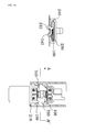
- FIG. 1 shows a state that a slider assembly according to the present invention is coupled to tapes
- FIG. 2 is a disassembled perspective view of the slider assembly shown in FIG. 1 .
- a slider assembly includes: a slider 100 which is shaped in a container having an opened bottom and has a channel 101 formed by both edges, through which teeth 20 pass; a locking unit 200 fixed to an end of a tape 12 to limit movement of the slider 100, and a bottom stop 300 which is fixed to an end of the tape 12 and allows the locking unit 200 to control the movement of the slider 100.
- Teeth 20 and 30 have a space receiving both edges of the slider 100.
- FIGS. 3A and 3B show a slider 100 applied to the present invention, respectively.
- the slider 100 has a single body 101, and is shaped in a rectangular box of which a front inlet and a rear outlet communicate with the inside of the rectangular body.
- both inner sidewalls 103 are curved inward to form edges 104 and 105 facing each other, and thus a channel 101 is resultantly defined in a lengthwise direction by the edges 104 and 105 and the inner sidewalls 103.
- edges 104 and 105 in the inlet of the body 102 form a smooth curved portion such that the edges 104 and 105 are smoothly coupled with the teeth 20 and 30.
- a position determining protrusion 107 is protruded from a rear surface at a middle position of the inlet.
- hook pieces 106 and 108 spaced apart by a predetermined interval from each other are protruded from both inner sidewalls, and interact with a stopper of the locking unit 200 to be described later.
- the hook piece 106 positioned at the front side is further protruded than the hook piece 108 positioned at the rear side, and a taper is formed at the rear side of each of the hook pieces 106 and 108.
- the hook piece 106 is installed for the purpose of pressurizing the stopper of the locking unit 200, and the hook piece 108 is installed for the hooking thereof to the stopper of the locking unit 200.
- a tap holder 110 is formed to a surface of the body 102, for example, by a screw, and is fixedly inserted into a full tap 120 as shown in FIG. 1 .
- FIGS. 4A , 4B , 4C , and 4D show a locking unit 200 according to the present invention, respectively.
- the locking unit 200 includes a main body 210 with an insertion hole 217 formed at the center thereof, stoppers 230 and 240 in one pair, which are mounted on a surface of the main body 210 and are coupled to each other with the spring 234 in-between while facing each other, and a cover 220 separably coupled to the main body 210 so as to cover the surface of the main body 210.
- a support protrusion 215 is horizontally protruded from the front side of the main body 210 and contacts and supports the first teeth 20 and 30 together with a protrusion of the bottom stop 300 to be described later.
- a groove 216 is formed at an upper surface of the support protrusion 215.
- a receiving space 212 for receiving the stoppers 230 and 240 is formed in the main body 210, a boss 214 into which an insert 233 with a thread groove formed at an outer circumference thereof for coupling with the cover 220 is inserted is integrally, protrudingly formed in the main body 210, and an insertion opening 217 positioned between the facing stoppers 230 and 240 is formed. Also, flanges 213 are protruded in the lengthwise direction from both sides of the main body 210, and the edges of the slider 100 are positioned under the flanges 213 such that the slider 100 is prevented from being released upward.
- Stop jaws 218 are formed at both sides of the main body 210 such that the slider 100 no longer moves backward.
- the stoppers 230 and 240 are positioned at edges of the insertion opening 217 and are provided with contacts 232 and 242 facing each other.
- the contacts 232 and 242 are positioned under the stoppers 230 and 240 positioned oppositely. That is, the state that the stoppers 230 and 240 are spaced apart from each other is shown in FIG. 4D , but in the state that the stoppers 230 and 240 are coupled with the spring 234 in-between, the contacts 232 and 242 are positioned under the stoppers 230 and 240 positioned oppositely.
- contact surfaces of the contacts 232 and 242 are inclined so as to be matched with the shape of the anchor contacting the contacts 232 and 242.
- FIGS. 5A and 5B show a bottom stop 300 applied to the present invention, respectively.
- the bottom stop 300 is fixed to an end portion of one of the tapes 12 and is coupled with or separated from the locking unit 200 to control the operation of the stoppers 230 and 240 of the locking unit 200.
- An anchor 310 is protrudingly formed on a surface of the bottom stop 300 and is inserted into the insertion opening 217 formed in the main body 210.
- a support protrusion 320 is vertically protruded from the front surface of the bottom stop 300, and a groove 322 is formed at an upper portion of the support protrusion 320.
- the anchor 310 shaped in a hemisphere is supported by a cylindrical support 312, and the support 312 has a diameter which is less than the diameter of the hemispherical anchor 310 such that a hook jaw 314 is formed at a boundary therebetween.
- FIG. 6 shows one of teeth 20 applied to the present invention.
- Each of the teeth 20 is formed in an integral body, and includes a meshing part 26 and attachment parts 21 and 22.
- the meshing part 26 has a groove 25 formed at one side and a protrusion formed at the opposite side for the meshing. Therefore, the teeth 20 in one side are meshed with the teeth 30 in the other side in such a way that the protrusions of the teeth 20 in one side are received in the grooves of the teeth 30 in the other side as shown in FIG. 1 .
- the attachment parts 21 and 22 are shaped in "C" such that a space 24 receiving the edges 104 and 105 of the slider 100 is formed therebetween.
- the lower attachment part 22 is formed relatively longer than the upper attachment part 21, and a coupling protrusion 23 is formed on the lower attachment part 22 and is inserted in the tape 10 such that the teeth 20 are fixed to the tape 10.
- FIGS. 7A to 7C show movement of the stoppers 230 and 240 depending on forward and backward movement of the bottom stop 300 and hooking operation of the hook pieces 106 and 108 of the slider 100, in which left drawings of FIGS. 7A to 7C are sectional views taken along lines A-A' of right drawings.
- the locking unit 200 is fixed at the end portion of the tape 10 where the teeth 20 are disposed, and the bottom stop 300 is fixed at the end portion where the teeth 30 are disposed.
- the edges 104 and 105 of the slider 100 move along the bottoms of the flanges 213 formed at both sides of the main body 210 of the locking unit 200, as described above.
- the restoring force of the spring 234 allows the stoppers 230 and 240 spaced far to forcibly narrow, and simultaneously when the hook piece 108 passes through the stoppers 230 and 240 and moves backward, the stoppers 230 and 240 are again protruded between the hook pieces 106 and 108 due to the restoring force of the spring 234.
- FIG. 7A shows a state of the stoppers 230 and 240 before the bottom stop 300 is coupled to the locking unit 200.
- the first coupled state when the stoppers 230 and 240 are pushed in a direction distant from each other, the contacts 232 and 242 approach each other on the contrary. Since the restoring force of the spring 234 fully acts on the stoppers 230 and 240, the stoppers 230 and 240 are in the most distant state.
- the hook piece 108 is hooked by the stoppers 230 and 240 such that the hook piece 108 does not move forward and also dose not move backward due to the stop jaw 218 of the main body 210 of the locking unit 200.
- the slider 100 is fixed to a constant position before the bottom stop 300 is coupled, a user can find the slider 100 rapidly and conveniently when fastening the zipper.
- FIG. 7B shows a state that the bottom stop 300 is coupled with the locking unit 200.
- the support protrusion 215 of the main body 210 of the locking unit 200 and the support protrusion 320 of the bottom stop 300 come close to each other and are coupled to thereby support the first teeth 20 and 30, and the groove 216 of the support protrusion 215 and the groove 322 of the support protrusion 320 are joined to form a groove, which receives the position determining protrusion 107.
- both edges of the stoppers 230 and 240 are pushed inward further than the end portion of the hook piece 108 such that the hook piece 108 can move freely.
- the slider 100 moves in a state that the edges 104 and 105 of the slider 100 are received in the receiving space 24 of the teeth 20 and 30, and in this state, the protrusions of the adjacent teeth 20 and 30 are inserted into the groove 25 and thus the teeth 20 and 30 are meshed, i.e., the zipper is fastened.
- FIG. 7C shows a state that the bottom stop 300 is separated from the locking unit 200.
- the hook piece 106 pushes the stoppers 230 and 240 and thus the stoppers 230 and 240 are brought to the nearest position, but the interval between the contacts 232 and 242 goes to the farthest position. Since the interval is wider than the diameter of the anchor 310 of the bottom stop 300, the bottom stop 300 can be smoothly separated.
Abstract
Description
- The present invention relates to a slider assembly applied to a zipper.
- Generally, a zipper is installed in bags, clothes, etc. to bind the edges of an opening, and is so very simple and convenient that it is widely used.
- In a brief examination of a conventional zipper structure, teeth are arranged at each of opposing edges of a pair of tapes of fabric, and a slider with a structure that a front side and a rear side communicate with each other is coupled to one of the pair of tapes.
- When the slider moves in a forward direction and the rows of teeth enter into the slider, the rows of teeth are interlocked with each other inside the slider and then are released through the rear side. On the contrary, when the slider moves in a backward direction, the interlocked teeth are separated and then the separated teeth are released through the front side.
- However, the conventional zipper has several problems.
- In detail, in order to fasten a zipper, a bottom stop of an end of a tape where the slider is not coupled should be inserted into the slider through the front side of the slider. However, if a user wears, for example, gloves, the user cannot perform a detail action and thus has a difficulty in inserting the bottom stop.
- Also, in case some of a seam in the back side of the tape rear is taken to the inside of the slider, the movement of the slider stops. If the slider is forcibly moved, the seam is further taken so that the slider does not operate.
- Further, since the slider does not stay at a constant site but moves forward or backward, users sometimes have a difficulty in rapidly grasping the slider.
- Thus, the conventional zipper has a limitation in that the foregoing drawbacks cannot be solved if the structure thereof is not basically changed.
- Meanwhile,
US Patent 4,326,319 discloses a slider fastener which includes a first terminal provided with a locking element, and a second terminal coupled with the first terminal as the first terminal is inserted into the second terminal and rotates. However, since the second terminal is shaped in a container and is coupled with the first terminal as the first terminal rotates, two continuous operations should be performed for the coupling. Also, if a foreign material is introduced into the second terminal, the slider fastener has a fatal drawback in that the coupling is not achieved. - Accordingly, an object of the present invention is to provide a slider assembly with a completely novel concept and structure.
- Another object of the present invention is to provide a slider assembly which can secure reliability for coupling and separation of teeth.
- A further another object of the present invention is to provide a slider assembly which can perform coupling and separation of teeth.
- Still another object of the present invention is to provide a slider assembly with a slider always maintaining a constant position in a state that the teeth are separated.
- According to an aspect of the present invention, there is provided a slider assembly including: a slider shaped in a cylinder having an opened bottom, the slider of which both edges coupled with teeth are curved inward; a bottom stop fixed to an end of one side tape; and a locking unit fixed to an end of the other side tape to limit movement of the slider, wherein the locking unit allows for the movement of the slider by coupling with or separation from the bottom stop, and the teeth has a space for receiving the edge of the slider.
- The slider may include a hook piece which is protruded from an inner wall of the slider, the locking unit may have stoppers in one pair which are coupled with facing each other with a spring in-between to be subject to a restoring force of the spring, the bottom stop has a anchor protruded vertically, and as the anchor is coupled with the stoppers, the stoppers in one pair are repelled each other or near each other such that the hook piece is hooked or not hooked to each of the stoppers.
- The slider may include a pressure hook piece which is further protruded than the hook piece and is formed on the inner wall at a front side spaced apart from the hook piece, and as the pressure hook piece pressurizes each of the stoppers in one pair, the anchor is separated from the stoppers.
- The locking unit may comprise: a main body formed at a center thereof with an opening; stoppers in one pair which are received on a surface of the main body, coupled to each other with a spring in-between and have a contact formed at a position intersecting each other; and a cover separably coupled to the main body so as to cover the surface of the main body.
- The locking unit may include: a flange which is protruded in a lengthwise direction from both sides of the main body such that each of the edges of the slider is positioned under the flange; and a stop jaw may be horizontally protruded from both sides of a rear end of the main body to limit reward movement of the slider.
- The bottom stop may have a hemi-spherical anchor protruded vertically, the anchor being supported by a supporter having a width less than a diameter of the anchor, wherein as the anchor passes between the contacts and is hooked on a hook jaw formed at a boundary between the anchor and the supporter, the separation of the anchor is prevented.
- The teeth may have a meshing part and an attachment part integrally formed, the meshing part may have a groove formed at one side surface thereof for meshing, a protrusion formed at an opposing side surface, and the attachment part may be shaped in "C" and have a space for receiving the edge of the slider in the "C"-shaped attachment part, and the tape is fixed under the attachment part.
- According to the above structure, even when a user cannot perform a detail action by hand, the coupling and separation of the teeth can be always performed reliably.
- Also, a rapid coupling between the teeth and the slider can be obtained by a single simple action, i.e., pressure in the vertical direction.
- Further, in a state that the teeth are separated, the slider can always maintain a constant position.
- Furthermore, the possibility that some of a seam is taken to the inside of the slider can be minimized.
- The above objects and other advantages of the present invention will become more apparent by describing in detail exemplary embodiments thereof with reference to the attached drawings in which:
-
FIG. 1 shows a state that a slider assembly according to the present invention is coupled to tapes. -
FIG. 2 is a disassembled perspective view of a slider assembly according to the present invention. -
FIGS. 3A and 3B show aslider 100 applied to the present invention, respectively. -
FIGS. 4A ,4B ,4C , and4D show alocking unit 200 according to the present invention, respectively. -
FIGS. 5A and 5B show abottom stop 300 applied to the present invention, respectively. -
FIG. 6 shows atooth 20 applied to the present invention. -
FIGS. 7A to 7C show movement of the stopper depending on forward and backward movement of the bottom stop and hooking operation of the hook piece of the slider, in which left drawings ofFIGS. 7A to 7C are sectional views taken along lines A-A' of right drawings. - Now, exemplary embodiments of the present invention will be described in detail with reference to the accompanying drawings.
-
FIG. 1 shows a state that a slider assembly according to the present invention is coupled to tapes, andFIG. 2 is a disassembled perspective view of the slider assembly shown inFIG. 1 . - As shown in
FIGS. 1 and2 , a slider assembly includes: aslider 100 which is shaped in a container having an opened bottom and has achannel 101 formed by both edges, through whichteeth 20 pass; alocking unit 200 fixed to an end of atape 12 to limit movement of theslider 100, and abottom stop 300 which is fixed to an end of thetape 12 and allows thelocking unit 200 to control the movement of theslider 100.Teeth slider 100. - Hereinafter, respective elements constituting the slider assembly will be described in detail. For the convenience of description, the movement of the
slider 100 for coupling ofteeth slider 100 for separation of theengaged teeth -
FIGS. 3A and 3B show aslider 100 applied to the present invention, respectively. - The
slider 100 has asingle body 101, and is shaped in a rectangular box of which a front inlet and a rear outlet communicate with the inside of the rectangular body. - End portions of both
inner sidewalls 103 are curved inward to formedges channel 101 is resultantly defined in a lengthwise direction by theedges inner sidewalls 103. - Preferably, the
edges body 102 form a smooth curved portion such that theedges teeth position determining protrusion 107 is protruded from a rear surface at a middle position of the inlet. - Referring to
FIG. 3B ,hook pieces locking unit 200 to be described later. Thehook piece 106 positioned at the front side is further protruded than thehook piece 108 positioned at the rear side, and a taper is formed at the rear side of each of thehook pieces - As described later, the
hook piece 106 is installed for the purpose of pressurizing the stopper of thelocking unit 200, and thehook piece 108 is installed for the hooking thereof to the stopper of thelocking unit 200. - A
tap holder 110 is formed to a surface of thebody 102, for example, by a screw, and is fixedly inserted into afull tap 120 as shown inFIG. 1 . -
FIGS. 4A ,4B ,4C , and4D show alocking unit 200 according to the present invention, respectively. - The
locking unit 200 includes amain body 210 with aninsertion hole 217 formed at the center thereof,stoppers main body 210 and are coupled to each other with thespring 234 in-between while facing each other, and acover 220 separably coupled to themain body 210 so as to cover the surface of themain body 210. - Preferably, a
support protrusion 215 is horizontally protruded from the front side of themain body 210 and contacts and supports thefirst teeth bottom stop 300 to be described later. Agroove 216 is formed at an upper surface of thesupport protrusion 215. - A receiving
space 212 for receiving thestoppers main body 210, aboss 214 into which aninsert 233 with a thread groove formed at an outer circumference thereof for coupling with thecover 220 is inserted is integrally, protrudingly formed in themain body 210, and aninsertion opening 217 positioned between the facingstoppers flanges 213 are protruded in the lengthwise direction from both sides of themain body 210, and the edges of theslider 100 are positioned under theflanges 213 such that theslider 100 is prevented from being released upward. - Stop
jaws 218 are formed at both sides of themain body 210 such that theslider 100 no longer moves backward. - The
stoppers insertion opening 217 and are provided withcontacts contacts stoppers stoppers FIG. 4D , but in the state that thestoppers spring 234 in-between, thecontacts stoppers - Therefore, when the
contacts stoppers contacts - Preferably, contact surfaces of the
contacts contacts -
FIGS. 5A and 5B show abottom stop 300 applied to the present invention, respectively. - The
bottom stop 300 is fixed to an end portion of one of thetapes 12 and is coupled with or separated from thelocking unit 200 to control the operation of thestoppers locking unit 200. - An
anchor 310 is protrudingly formed on a surface of thebottom stop 300 and is inserted into theinsertion opening 217 formed in themain body 210. - Also, a
support protrusion 320 is vertically protruded from the front surface of thebottom stop 300, and agroove 322 is formed at an upper portion of thesupport protrusion 320. - Referring to
FIG. 5B , theanchor 310 shaped in a hemisphere is supported by acylindrical support 312, and thesupport 312 has a diameter which is less than the diameter of thehemispherical anchor 310 such that ahook jaw 314 is formed at a boundary therebetween. -
FIG. 6 shows one ofteeth 20 applied to the present invention. - Each of the
teeth 20 is formed in an integral body, and includes a meshingpart 26 andattachment parts part 26 has agroove 25 formed at one side and a protrusion formed at the opposite side for the meshing. Therefore, theteeth 20 in one side are meshed with theteeth 30 in the other side in such a way that the protrusions of theteeth 20 in one side are received in the grooves of theteeth 30 in the other side as shown inFIG. 1 . - The
attachment parts space 24 receiving theedges slider 100 is formed therebetween. Thelower attachment part 22 is formed relatively longer than theupper attachment part 21, and acoupling protrusion 23 is formed on thelower attachment part 22 and is inserted in thetape 10 such that theteeth 20 are fixed to thetape 10. - Hereinafter, the coupling and operation of the slider assembly with above-described structure will be described.
-
FIGS. 7A to 7C show movement of thestoppers bottom stop 300 and hooking operation of thehook pieces slider 100, in which left drawings ofFIGS. 7A to 7C are sectional views taken along lines A-A' of right drawings. - The
locking unit 200 is fixed at the end portion of thetape 10 where theteeth 20 are disposed, and thebottom stop 300 is fixed at the end portion where theteeth 30 are disposed. - When the
slider 100 is horizontally pushed with respect to thelocking unit 200, theedges slider 100 move along the bottoms of theflanges 213 formed at both sides of themain body 210 of thelocking unit 200, as described above. - At this time, as shown in
FIG. 7A , since thestoppers locking unit 200 are in a state protruded to the most external positions, thehook piece 108 is hooked to thestoppers slider 100 moves. - When the
slider 100 is forcibly pushed backward, the restoring force of thespring 234 allows thestoppers hook piece 108 passes through thestoppers stoppers hook pieces spring 234. - In this state, when the force applied to the
slider 100 is removed, theslider 100 is locked in the state as shown inFIG. 7A , and thus the coupling of theslider 100 and thelocking unit 200 are completed. -
FIG. 7A shows a state of thestoppers bottom stop 300 is coupled to thelocking unit 200. In the first coupled state, when thestoppers contacts spring 234 fully acts on thestoppers stoppers - In this state, the
hook piece 108 is hooked by thestoppers hook piece 108 does not move forward and also dose not move backward due to thestop jaw 218 of themain body 210 of thelocking unit 200. As a result, since theslider 100 is fixed to a constant position before thebottom stop 300 is coupled, a user can find theslider 100 rapidly and conveniently when fastening the zipper. -
FIG. 7B shows a state that thebottom stop 300 is coupled with thelocking unit 200. - Upon coupling, when the
hemispherical anchor 310 rises to pressurize thecontacts stoppers contacts anchor 310 so that the distance between thecontacts hook jaw 314 formed at a boundary with thesupport 312. As a result, both edges of thestoppers hook jaw 108. This is because the diameter of thesupport 312 is less than the diameter of theanchor 310, as described above. - Also, the
support protrusion 215 of themain body 210 of thelocking unit 200 and thesupport protrusion 320 of thebottom stop 300 come close to each other and are coupled to thereby support thefirst teeth groove 216 of thesupport protrusion 215 and thegroove 322 of thesupport protrusion 320 are joined to form a groove, which receives theposition determining protrusion 107. - In this state, as shown in
FIG. 7B , both edges of thestoppers hook piece 108 such that thehook piece 108 can move freely. - Therefore, when a user pulls the
full tap 120 upward and moves the same forward, theslider 100 moves in a state that theedges slider 100 are received in the receivingspace 24 of theteeth adjacent teeth groove 25 and thus theteeth -
FIG. 7C shows a state that thebottom stop 300 is separated from thelocking unit 200. - When a user tries to unfasten the zipper by separating the
teeth slider 100 downward to move the slider backward, whereby thehook piece 106 positioned at the front side contacts thestoppers - At this time, when the
slider 100 is strongly pulled, thehook piece 106 pushes thestoppers stoppers contacts anchor 310 of thebottom stop 300, thebottom stop 300 can be smoothly separated. - While this invention has been particularly shown and described with reference to preferred embodiments thereof, it will be understood by those skilled in the art that various changes in form and details may be made therein without departing from the spirit and scope of the invention. Thus, the scope of the present invention is to be determined by the broadest permissible interpretation of the following claims and their equivalents, and shall not be restricted or limited by the foregoing detailed description.
Claims (7)
- A slider assembly comprising:a slider shaped in a cylinder having an opened bottom, the slider of which both edges coupled with teeth are curved inward;a bottom stop fixed to an end of one side tape; anda locking unit fixed to an end of the other side tape, the locking unit being separably coupled with the slider disposed above the locking unit to limit movement of the slider,wherein the locking unit allows for or blocks the movement of the slider by coupling with or separation, in a vertical direction, from the bottom stop.
- The slider assembly of claim 1, wherein the slider comprises a hook piece which is protruded from an inner wall of the slider,
the locking unit has stoppers in one pair which are coupled with facing each other with a spring in-between to experience a restoring force of the spring,
the bottom stop has a anchor protruded vertically, and
as the anchor is coupled with the stoppers, the stoppers in one pair are repelled each other or near each other such that the hook piece is hooked or not hooked to each of the stoppers. - The slider assembly of claim 2, wherein the slider comprises a pressure hook piece which is further protruded than the hook piece and is formed on the inner wall at a front side spaced apart from the hook piece, and as the pressure hook piece pressurizes each of the stoppers in one pair, the anchor is separated from the stoppers.
- The slider assembly of claim 1, wherein the locking unit comprises:a main body formed at a center thereof with an opening;stoppers in one pair which are received on a surface of the main body, coupled to each other while facing each other with a spring in-between and have a contact formed at a position intersecting each other; anda cover separably coupled to the main body so as to cover the surface of the main body.
- The slider assembly of claim 4, wherein the locking unit comprises:a flange which is protruded in a lengthwise direction from both sides of the main body such that each of the edges of the slider is positioned under the flange; anda stop jaw which is horizontally protruded from both sides of a rear end of the main body to limit reward movement of the slider.
- The slider assembly of claim 4, wherein the bottom stop has a hemispherical anchor protruded vertically, the anchor being supported by a supporter having a width less than a diameter of the anchor,
wherein as the anchor passes between the contacts and is hooked on a hook jaw formed at a boundary between the anchor and the supporter, the separation of the anchor is prevented. - The slider assembly of claim 1, wherein the teeth have a meshing part and an attachment part integrally formed,
the meshing part has a groove formed at one side surface thereof for meshing, and a protrusion formed at an opposing side surface,
the attachment part is shaped in 'C' and has a space for receiving the edge of the slider in the C-shaped attachment part, and
the tape is fixed to a lower portion of the attachment part.
Applications Claiming Priority (2)
| Application Number | Priority Date | Filing Date | Title |
|---|---|---|---|
| KR1020120014943A KR101196382B1 (en) | 2012-02-14 | 2012-02-14 | Slider assembly |
| PCT/KR2013/001034 WO2013122357A1 (en) | 2012-02-14 | 2013-02-08 | Slider assembly |
Publications (3)
| Publication Number | Publication Date |
|---|---|
| EP2815672A1 true EP2815672A1 (en) | 2014-12-24 |
| EP2815672A4 EP2815672A4 (en) | 2015-09-30 |
| EP2815672B1 EP2815672B1 (en) | 2017-04-12 |
Family
ID=47563748
Family Applications (1)
| Application Number | Title | Priority Date | Filing Date |
|---|---|---|---|
| EP13749462.1A Not-in-force EP2815672B1 (en) | 2012-02-14 | 2013-02-08 | Slider assembly |
Country Status (7)
| Country | Link |
|---|---|
| US (1) | US9173457B2 (en) |
| EP (1) | EP2815672B1 (en) |
| JP (1) | JP5886959B2 (en) |
| KR (1) | KR101196382B1 (en) |
| CN (1) | CN104125787B (en) |
| CA (1) | CA2795095C (en) |
| WO (1) | WO2013122357A1 (en) |
Families Citing this family (8)
| Publication number | Priority date | Publication date | Assignee | Title |
|---|---|---|---|---|
| US9661900B2 (en) * | 2012-07-05 | 2017-05-30 | Ykk Corporation | Slide fastener attachment method |
| US9693606B2 (en) | 2012-12-31 | 2017-07-04 | KMK Zipper Co., Ltd. | Slider assembly and zipper comprising same |
| USD803096S1 (en) * | 2016-06-17 | 2017-11-21 | Ykk Corporation | Slider for slide fastener |
| USD803095S1 (en) * | 2016-06-17 | 2017-11-21 | Ykk Corporation | Slider for slide fastener |
| CN108024601A (en) * | 2016-07-19 | 2018-05-11 | 李知惠 | Zipper for slide fastener chain |
| CN106723698A (en) * | 2017-03-10 | 2017-05-31 | 惠安惠诚手袋有限公司 | Water-proof air-tight slide fastener |
| CN106820471A (en) * | 2017-03-27 | 2017-06-13 | 浙江伟星实业发展股份有限公司 | A kind of slide fastener |
| CN108813830B (en) * | 2018-04-02 | 2024-04-02 | 王元林 | Multifunctional pull head |
Family Cites Families (20)
| Publication number | Priority date | Publication date | Assignee | Title |
|---|---|---|---|---|
| US2123512A (en) * | 1936-10-22 | 1938-07-12 | Whitehall Patents Corp | Separable fastener |
| US2583386A (en) * | 1945-03-28 | 1952-01-22 | Conmar Prod Corp | Separable slide fastener |
| US2728125A (en) * | 1954-02-05 | 1955-12-27 | Scovill Manufacturing Co | Zippers of the separable end type |
| US3238285A (en) * | 1963-02-19 | 1966-03-01 | Louis H Morin | Method of forming scoop structures to accommodate sliders operating on one face of the scoop structures |
| US4326319A (en) | 1979-03-15 | 1982-04-27 | Friedberg Martin F | Slide fastener with improved end connections |
| US4232429A (en) * | 1978-09-07 | 1980-11-11 | Friedberg Martin F | Sliding fastener |
| US4232430A (en) * | 1979-03-15 | 1980-11-11 | Friedberg Martin F | Device for connecting the ends of a separable zipper |
| KR900005050Y1 (en) * | 1988-01-18 | 1990-06-08 | 김삼홍 | Slide fastener having a lock and seperating device |
| JPH0793888B2 (en) * | 1990-12-27 | 1995-10-11 | ワイケイケイ株式会社 | Slide fastener open / close fitting |
| US5131120A (en) * | 1991-12-23 | 1992-07-21 | Yoshida Kogyo K.K. | Separable bottom end assembly for slide fastener |
| JP2774218B2 (en) * | 1992-07-31 | 1998-07-09 | ワイケイケイ株式会社 | Hidden slide fastener separable bottom end stop fitting and separable bottom end stop insertion method |
| KR940025967U (en) * | 1993-05-14 | 1994-12-08 | 조현민 | Slide Fasteners and Sliders |
| US5396685A (en) * | 1994-01-14 | 1995-03-14 | Wilk; Peter J. | Zipper-type closure method |
| JPH08313A (en) * | 1994-06-27 | 1996-01-09 | Ykk Kk | Slide fastener |
| JPH11221105A (en) * | 1997-11-20 | 1999-08-17 | Ykk Corp | Opening and fitting tool for slide fasteners |
| JP3541270B2 (en) | 1999-02-05 | 2004-07-07 | モリト株式会社 | Slide fastener slider |
| US6502285B2 (en) | 2001-03-16 | 2003-01-07 | Alice Mary Kiely | Immobilized and aligned closure systems |
| DE10146151B4 (en) * | 2001-07-13 | 2008-05-08 | Shih-Chang Wang | zipper |
| JP3733343B2 (en) * | 2002-05-20 | 2006-01-11 | Ykk株式会社 | Separation insert for slide fastener |
| JP4651634B2 (en) * | 2007-03-15 | 2011-03-16 | Ykk株式会社 | Hidden slide fastener |
-
2012
- 2012-02-14 KR KR1020120014943A patent/KR101196382B1/en active IP Right Grant
- 2012-11-06 US US13/669,581 patent/US9173457B2/en not_active Expired - Fee Related
- 2012-11-08 CA CA2795095A patent/CA2795095C/en not_active Expired - Fee Related
-
2013
- 2013-02-08 JP JP2014522767A patent/JP5886959B2/en not_active Expired - Fee Related
- 2013-02-08 WO PCT/KR2013/001034 patent/WO2013122357A1/en active Application Filing
- 2013-02-08 CN CN201380009496.2A patent/CN104125787B/en not_active Expired - Fee Related
- 2013-02-08 EP EP13749462.1A patent/EP2815672B1/en not_active Not-in-force
Also Published As
| Publication number | Publication date |
|---|---|
| KR101196382B1 (en) | 2012-11-02 |
| CN104125787A (en) | 2014-10-29 |
| US9173457B2 (en) | 2015-11-03 |
| CA2795095A1 (en) | 2013-08-14 |
| EP2815672A4 (en) | 2015-09-30 |
| CA2795095C (en) | 2018-04-24 |
| CN104125787B (en) | 2016-12-14 |
| JP5886959B2 (en) | 2016-03-16 |
| WO2013122357A1 (en) | 2013-08-22 |
| EP2815672B1 (en) | 2017-04-12 |
| US20130205549A1 (en) | 2013-08-15 |
| JP2014523788A (en) | 2014-09-18 |
Similar Documents
| Publication | Publication Date | Title |
|---|---|---|
| EP2815672B1 (en) | Slider assembly | |
| KR101153549B1 (en) | Slider for concealed type slide fastener with separable bottom end stop | |
| TWI355904B (en) | Slider for slide fastener | |
| US10292461B2 (en) | Slide fastener | |
| KR100592487B1 (en) | Reverse-separating device for slide fastener | |
| KR101413400B1 (en) | Slider for slide fastener | |
| US7204002B2 (en) | Buckle and baby carrier using the same | |
| JPS6324361B2 (en) | ||
| JP6688305B2 (en) | Zipper slider | |
| US10212992B2 (en) | Slider for slide fastener | |
| KR20130124580A (en) | Slide fastener with openable/meshable strips | |
| US10588383B2 (en) | Buckle | |
| US9693606B2 (en) | Slider assembly and zipper comprising same | |
| KR101069091B1 (en) | Buckle | |
| KR101721337B1 (en) | Control device, band and band adjusting device including the same | |
| CN108741458B (en) | Zipper | |
| CN208114135U (en) | Rope fastener | |
| WO2020161848A1 (en) | Slider for concealed slide fastener | |
| US10882665B1 (en) | Child resistant slider zipper | |
| EP2517589A1 (en) | Buckle | |
| US11388960B2 (en) | Snap button, and a female component for such snap button | |
| TW201424618A (en) | Slider for slide fasteners | |
| CN111150180B (en) | Fastener for slide fastener | |
| WO2021090494A1 (en) | Slide fastener | |
| CN110710764A (en) | Slide fastener |
Legal Events
| Date | Code | Title | Description |
|---|---|---|---|
| PUAI | Public reference made under article 153(3) epc to a published international application that has entered the european phase |
Free format text: ORIGINAL CODE: 0009012 |
|
| 17P | Request for examination filed |
Effective date: 20140812 |
|
| AK | Designated contracting states |
Kind code of ref document: A1 Designated state(s): AL AT BE BG CH CY CZ DE DK EE ES FI FR GB GR HR HU IE IS IT LI LT LU LV MC MK MT NL NO PL PT RO RS SE SI SK SM TR |
|
| AX | Request for extension of the european patent |
Extension state: BA ME |
|
| DAX | Request for extension of the european patent (deleted) | ||
| REG | Reference to a national code |
Ref country code: DE Ref legal event code: R079 Ref document number: 602013019788 Country of ref document: DE Free format text: PREVIOUS MAIN CLASS: A44B0019260000 Ipc: A44B0019360000 |
|
| RA4 | Supplementary search report drawn up and despatched (corrected) |
Effective date: 20150902 |
|
| RIC1 | Information provided on ipc code assigned before grant |
Ipc: A44B 19/30 20060101ALI20150827BHEP Ipc: A44B 19/06 20060101ALI20150827BHEP Ipc: A44B 19/38 20060101ALI20150827BHEP Ipc: A44B 19/60 20060101ALI20150827BHEP Ipc: A44B 19/24 20060101ALI20150827BHEP Ipc: A44B 19/36 20060101AFI20150827BHEP Ipc: A44B 19/26 20060101ALI20150827BHEP |
|
| RAP1 | Party data changed (applicant data changed or rights of an application transferred) |
Owner name: KMK CO., LTD |
|
| RIN1 | Information on inventor provided before grant (corrected) |
Inventor name: LEE, OK-KYUNG |
|
| GRAP | Despatch of communication of intention to grant a patent |
Free format text: ORIGINAL CODE: EPIDOSNIGR1 |
|
| INTG | Intention to grant announced |
Effective date: 20161018 |
|
| GRAS | Grant fee paid |
Free format text: ORIGINAL CODE: EPIDOSNIGR3 |
|
| GRAA | (expected) grant |
Free format text: ORIGINAL CODE: 0009210 |
|
| AK | Designated contracting states |
Kind code of ref document: B1 Designated state(s): AL AT BE BG CH CY CZ DE DK EE ES FI FR GB GR HR HU IE IS IT LI LT LU LV MC MK MT NL NO PL PT RO RS SE SI SK SM TR |
|
| REG | Reference to a national code |
Ref country code: GB Ref legal event code: FG4D |
|
| REG | Reference to a national code |
Ref country code: CH Ref legal event code: EP |
|
| REG | Reference to a national code |
Ref country code: IE Ref legal event code: FG4D |
|
| REG | Reference to a national code |
Ref country code: AT Ref legal event code: REF Ref document number: 883008 Country of ref document: AT Kind code of ref document: T Effective date: 20170515 |
|
| REG | Reference to a national code |
Ref country code: DE Ref legal event code: R096 Ref document number: 602013019788 Country of ref document: DE |
|
| REG | Reference to a national code |
Ref country code: NL Ref legal event code: MP Effective date: 20170412 |
|
| REG | Reference to a national code |
Ref country code: LT Ref legal event code: MG4D |
|
| REG | Reference to a national code |
Ref country code: AT Ref legal event code: MK05 Ref document number: 883008 Country of ref document: AT Kind code of ref document: T Effective date: 20170412 |
|
| PG25 | Lapsed in a contracting state [announced via postgrant information from national office to epo] |
Ref country code: NL Free format text: LAPSE BECAUSE OF FAILURE TO SUBMIT A TRANSLATION OF THE DESCRIPTION OR TO PAY THE FEE WITHIN THE PRESCRIBED TIME-LIMIT Effective date: 20170412 |
|
| PG25 | Lapsed in a contracting state [announced via postgrant information from national office to epo] |
Ref country code: GR Free format text: LAPSE BECAUSE OF FAILURE TO SUBMIT A TRANSLATION OF THE DESCRIPTION OR TO PAY THE FEE WITHIN THE PRESCRIBED TIME-LIMIT Effective date: 20170713 Ref country code: LT Free format text: LAPSE BECAUSE OF FAILURE TO SUBMIT A TRANSLATION OF THE DESCRIPTION OR TO PAY THE FEE WITHIN THE PRESCRIBED TIME-LIMIT Effective date: 20170412 Ref country code: AT Free format text: LAPSE BECAUSE OF FAILURE TO SUBMIT A TRANSLATION OF THE DESCRIPTION OR TO PAY THE FEE WITHIN THE PRESCRIBED TIME-LIMIT Effective date: 20170412 Ref country code: HR Free format text: LAPSE BECAUSE OF FAILURE TO SUBMIT A TRANSLATION OF THE DESCRIPTION OR TO PAY THE FEE WITHIN THE PRESCRIBED TIME-LIMIT Effective date: 20170412 Ref country code: FI Free format text: LAPSE BECAUSE OF FAILURE TO SUBMIT A TRANSLATION OF THE DESCRIPTION OR TO PAY THE FEE WITHIN THE PRESCRIBED TIME-LIMIT Effective date: 20170412 Ref country code: ES Free format text: LAPSE BECAUSE OF FAILURE TO SUBMIT A TRANSLATION OF THE DESCRIPTION OR TO PAY THE FEE WITHIN THE PRESCRIBED TIME-LIMIT Effective date: 20170412 Ref country code: NO Free format text: LAPSE BECAUSE OF FAILURE TO SUBMIT A TRANSLATION OF THE DESCRIPTION OR TO PAY THE FEE WITHIN THE PRESCRIBED TIME-LIMIT Effective date: 20170712 |
|
| PG25 | Lapsed in a contracting state [announced via postgrant information from national office to epo] |
Ref country code: LV Free format text: LAPSE BECAUSE OF FAILURE TO SUBMIT A TRANSLATION OF THE DESCRIPTION OR TO PAY THE FEE WITHIN THE PRESCRIBED TIME-LIMIT Effective date: 20170412 Ref country code: IS Free format text: LAPSE BECAUSE OF FAILURE TO SUBMIT A TRANSLATION OF THE DESCRIPTION OR TO PAY THE FEE WITHIN THE PRESCRIBED TIME-LIMIT Effective date: 20170812 Ref country code: RS Free format text: LAPSE BECAUSE OF FAILURE TO SUBMIT A TRANSLATION OF THE DESCRIPTION OR TO PAY THE FEE WITHIN THE PRESCRIBED TIME-LIMIT Effective date: 20170412 Ref country code: SE Free format text: LAPSE BECAUSE OF FAILURE TO SUBMIT A TRANSLATION OF THE DESCRIPTION OR TO PAY THE FEE WITHIN THE PRESCRIBED TIME-LIMIT Effective date: 20170412 Ref country code: BG Free format text: LAPSE BECAUSE OF FAILURE TO SUBMIT A TRANSLATION OF THE DESCRIPTION OR TO PAY THE FEE WITHIN THE PRESCRIBED TIME-LIMIT Effective date: 20170712 Ref country code: PL Free format text: LAPSE BECAUSE OF FAILURE TO SUBMIT A TRANSLATION OF THE DESCRIPTION OR TO PAY THE FEE WITHIN THE PRESCRIBED TIME-LIMIT Effective date: 20170412 |
|
| REG | Reference to a national code |
Ref country code: DE Ref legal event code: R097 Ref document number: 602013019788 Country of ref document: DE |
|
| PG25 | Lapsed in a contracting state [announced via postgrant information from national office to epo] |
Ref country code: CZ Free format text: LAPSE BECAUSE OF FAILURE TO SUBMIT A TRANSLATION OF THE DESCRIPTION OR TO PAY THE FEE WITHIN THE PRESCRIBED TIME-LIMIT Effective date: 20170412 Ref country code: RO Free format text: LAPSE BECAUSE OF FAILURE TO SUBMIT A TRANSLATION OF THE DESCRIPTION OR TO PAY THE FEE WITHIN THE PRESCRIBED TIME-LIMIT Effective date: 20170412 Ref country code: EE Free format text: LAPSE BECAUSE OF FAILURE TO SUBMIT A TRANSLATION OF THE DESCRIPTION OR TO PAY THE FEE WITHIN THE PRESCRIBED TIME-LIMIT Effective date: 20170412 Ref country code: SK Free format text: LAPSE BECAUSE OF FAILURE TO SUBMIT A TRANSLATION OF THE DESCRIPTION OR TO PAY THE FEE WITHIN THE PRESCRIBED TIME-LIMIT Effective date: 20170412 Ref country code: DK Free format text: LAPSE BECAUSE OF FAILURE TO SUBMIT A TRANSLATION OF THE DESCRIPTION OR TO PAY THE FEE WITHIN THE PRESCRIBED TIME-LIMIT Effective date: 20170412 |
|
| PLBE | No opposition filed within time limit |
Free format text: ORIGINAL CODE: 0009261 |
|
| STAA | Information on the status of an ep patent application or granted ep patent |
Free format text: STATUS: NO OPPOSITION FILED WITHIN TIME LIMIT |
|
| PG25 | Lapsed in a contracting state [announced via postgrant information from national office to epo] |
Ref country code: IT Free format text: LAPSE BECAUSE OF FAILURE TO SUBMIT A TRANSLATION OF THE DESCRIPTION OR TO PAY THE FEE WITHIN THE PRESCRIBED TIME-LIMIT Effective date: 20170412 Ref country code: SM Free format text: LAPSE BECAUSE OF FAILURE TO SUBMIT A TRANSLATION OF THE DESCRIPTION OR TO PAY THE FEE WITHIN THE PRESCRIBED TIME-LIMIT Effective date: 20170412 |
|
| REG | Reference to a national code |
Ref country code: FR Ref legal event code: PLFP Year of fee payment: 6 |
|
| 26N | No opposition filed |
Effective date: 20180115 |
|
| PGFP | Annual fee paid to national office [announced via postgrant information from national office to epo] |
Ref country code: DE Payment date: 20180227 Year of fee payment: 6 |
|
| PG25 | Lapsed in a contracting state [announced via postgrant information from national office to epo] |
Ref country code: SI Free format text: LAPSE BECAUSE OF FAILURE TO SUBMIT A TRANSLATION OF THE DESCRIPTION OR TO PAY THE FEE WITHIN THE PRESCRIBED TIME-LIMIT Effective date: 20170412 |
|
| REG | Reference to a national code |
Ref country code: CH Ref legal event code: PL |
|
| PG25 | Lapsed in a contracting state [announced via postgrant information from national office to epo] |
Ref country code: MC Free format text: LAPSE BECAUSE OF FAILURE TO SUBMIT A TRANSLATION OF THE DESCRIPTION OR TO PAY THE FEE WITHIN THE PRESCRIBED TIME-LIMIT Effective date: 20170412 |
|
| REG | Reference to a national code |
Ref country code: IE Ref legal event code: MM4A |
|
| REG | Reference to a national code |
Ref country code: BE Ref legal event code: MM Effective date: 20180228 |
|
| PG25 | Lapsed in a contracting state [announced via postgrant information from national office to epo] |
Ref country code: CH Free format text: LAPSE BECAUSE OF NON-PAYMENT OF DUE FEES Effective date: 20180228 Ref country code: LU Free format text: LAPSE BECAUSE OF NON-PAYMENT OF DUE FEES Effective date: 20180208 Ref country code: LI Free format text: LAPSE BECAUSE OF NON-PAYMENT OF DUE FEES Effective date: 20180228 |
|
| PG25 | Lapsed in a contracting state [announced via postgrant information from national office to epo] |
Ref country code: IE Free format text: LAPSE BECAUSE OF NON-PAYMENT OF DUE FEES Effective date: 20180208 |
|
| PG25 | Lapsed in a contracting state [announced via postgrant information from national office to epo] |
Ref country code: BE Free format text: LAPSE BECAUSE OF NON-PAYMENT OF DUE FEES Effective date: 20180228 |
|
| PGFP | Annual fee paid to national office [announced via postgrant information from national office to epo] |
Ref country code: GB Payment date: 20190226 Year of fee payment: 7 |
|
| PGFP | Annual fee paid to national office [announced via postgrant information from national office to epo] |
Ref country code: FR Payment date: 20190226 Year of fee payment: 7 |
|
| REG | Reference to a national code |
Ref country code: DE Ref legal event code: R119 Ref document number: 602013019788 Country of ref document: DE |
|
| PG25 | Lapsed in a contracting state [announced via postgrant information from national office to epo] |
Ref country code: DE Free format text: LAPSE BECAUSE OF NON-PAYMENT OF DUE FEES Effective date: 20190903 Ref country code: MT Free format text: LAPSE BECAUSE OF NON-PAYMENT OF DUE FEES Effective date: 20180208 |
|
| PG25 | Lapsed in a contracting state [announced via postgrant information from national office to epo] |
Ref country code: TR Free format text: LAPSE BECAUSE OF FAILURE TO SUBMIT A TRANSLATION OF THE DESCRIPTION OR TO PAY THE FEE WITHIN THE PRESCRIBED TIME-LIMIT Effective date: 20170412 |
|
| PG25 | Lapsed in a contracting state [announced via postgrant information from national office to epo] |
Ref country code: HU Free format text: LAPSE BECAUSE OF FAILURE TO SUBMIT A TRANSLATION OF THE DESCRIPTION OR TO PAY THE FEE WITHIN THE PRESCRIBED TIME-LIMIT; INVALID AB INITIO Effective date: 20130208 Ref country code: PT Free format text: LAPSE BECAUSE OF FAILURE TO SUBMIT A TRANSLATION OF THE DESCRIPTION OR TO PAY THE FEE WITHIN THE PRESCRIBED TIME-LIMIT Effective date: 20170412 |
|
| PG25 | Lapsed in a contracting state [announced via postgrant information from national office to epo] |
Ref country code: MK Free format text: LAPSE BECAUSE OF NON-PAYMENT OF DUE FEES Effective date: 20170412 Ref country code: CY Free format text: LAPSE BECAUSE OF FAILURE TO SUBMIT A TRANSLATION OF THE DESCRIPTION OR TO PAY THE FEE WITHIN THE PRESCRIBED TIME-LIMIT Effective date: 20170412 |
|
| PG25 | Lapsed in a contracting state [announced via postgrant information from national office to epo] |
Ref country code: AL Free format text: LAPSE BECAUSE OF FAILURE TO SUBMIT A TRANSLATION OF THE DESCRIPTION OR TO PAY THE FEE WITHIN THE PRESCRIBED TIME-LIMIT Effective date: 20170412 |
|
| GBPC | Gb: european patent ceased through non-payment of renewal fee |
Effective date: 20200208 |
|
| PG25 | Lapsed in a contracting state [announced via postgrant information from national office to epo] |
Ref country code: FR Free format text: LAPSE BECAUSE OF NON-PAYMENT OF DUE FEES Effective date: 20200229 Ref country code: GB Free format text: LAPSE BECAUSE OF NON-PAYMENT OF DUE FEES Effective date: 20200208 |