EP2815120B1 - Ensemble à cartouche de filtre et procédé de fabrication de celui-ci - Google Patents
Ensemble à cartouche de filtre et procédé de fabrication de celui-ci Download PDFInfo
- Publication number
- EP2815120B1 EP2815120B1 EP12868540.1A EP12868540A EP2815120B1 EP 2815120 B1 EP2815120 B1 EP 2815120B1 EP 12868540 A EP12868540 A EP 12868540A EP 2815120 B1 EP2815120 B1 EP 2815120B1
- Authority
- EP
- European Patent Office
- Prior art keywords
- arms
- retention
- fuel
- end cap
- filter element
- Prior art date
- Legal status (The legal status is an assumption and is not a legal conclusion. Google has not performed a legal analysis and makes no representation as to the accuracy of the status listed.)
- Active
Links
- 238000000034 method Methods 0.000 title claims description 4
- 238000004519 manufacturing process Methods 0.000 title description 5
- 239000000446 fuel Substances 0.000 claims description 75
- 230000014759 maintenance of location Effects 0.000 claims description 52
- 230000037361 pathway Effects 0.000 claims description 4
- 230000002250 progressing effect Effects 0.000 claims 1
- XLYOFNOQVPJJNP-UHFFFAOYSA-N water Substances O XLYOFNOQVPJJNP-UHFFFAOYSA-N 0.000 description 6
- 239000000853 adhesive Substances 0.000 description 5
- 230000001070 adhesive effect Effects 0.000 description 5
- 239000002245 particle Substances 0.000 description 5
- 238000001914 filtration Methods 0.000 description 4
- 239000012530 fluid Substances 0.000 description 3
- 239000002283 diesel fuel Substances 0.000 description 2
- 238000009434 installation Methods 0.000 description 2
- 229920002678 cellulose Polymers 0.000 description 1
- 239000001913 cellulose Substances 0.000 description 1
- 230000005465 channeling Effects 0.000 description 1
- 238000002485 combustion reaction Methods 0.000 description 1
- 239000000356 contaminant Substances 0.000 description 1
- 230000007613 environmental effect Effects 0.000 description 1
- 239000002657 fibrous material Substances 0.000 description 1
- 230000008014 freezing Effects 0.000 description 1
- 238000007710 freezing Methods 0.000 description 1
- 238000002347 injection Methods 0.000 description 1
- 239000007924 injection Substances 0.000 description 1
- 239000007788 liquid Substances 0.000 description 1
- 239000000463 material Substances 0.000 description 1
- 239000002184 metal Substances 0.000 description 1
- 239000012466 permeate Substances 0.000 description 1
- 238000011085 pressure filtration Methods 0.000 description 1
- 239000000047 product Substances 0.000 description 1
- 239000000243 solution Substances 0.000 description 1
- 239000002699 waste material Substances 0.000 description 1
Images


Classifications
-
- B—PERFORMING OPERATIONS; TRANSPORTING
- B01—PHYSICAL OR CHEMICAL PROCESSES OR APPARATUS IN GENERAL
- B01D—SEPARATION
- B01D29/00—Filters with filtering elements stationary during filtration, e.g. pressure or suction filters, not covered by groups B01D24/00 - B01D27/00; Filtering elements therefor
- B01D29/11—Filters with filtering elements stationary during filtration, e.g. pressure or suction filters, not covered by groups B01D24/00 - B01D27/00; Filtering elements therefor with bag, cage, hose, tube, sleeve or like filtering elements
- B01D29/13—Supported filter elements
- B01D29/15—Supported filter elements arranged for inward flow filtration
- B01D29/21—Supported filter elements arranged for inward flow filtration with corrugated, folded or wound sheets
-
- B—PERFORMING OPERATIONS; TRANSPORTING
- B01—PHYSICAL OR CHEMICAL PROCESSES OR APPARATUS IN GENERAL
- B01D—SEPARATION
- B01D2201/00—Details relating to filtering apparatus
- B01D2201/29—Filter cartridge constructions
- B01D2201/291—End caps
-
- B—PERFORMING OPERATIONS; TRANSPORTING
- B01—PHYSICAL OR CHEMICAL PROCESSES OR APPARATUS IN GENERAL
- B01D—SEPARATION
- B01D2201/00—Details relating to filtering apparatus
- B01D2201/30—Filter housing constructions
- B01D2201/301—Details of removable closures, lids, caps, filter heads
- B01D2201/305—Snap, latch or clip connecting means
-
- B—PERFORMING OPERATIONS; TRANSPORTING
- B01—PHYSICAL OR CHEMICAL PROCESSES OR APPARATUS IN GENERAL
- B01D—SEPARATION
- B01D2201/00—Details relating to filtering apparatus
- B01D2201/40—Special measures for connecting different parts of the filter
- B01D2201/4084—Snap or Seeger ring connecting means
-
- Y—GENERAL TAGGING OF NEW TECHNOLOGICAL DEVELOPMENTS; GENERAL TAGGING OF CROSS-SECTIONAL TECHNOLOGIES SPANNING OVER SEVERAL SECTIONS OF THE IPC; TECHNICAL SUBJECTS COVERED BY FORMER USPC CROSS-REFERENCE ART COLLECTIONS [XRACs] AND DIGESTS
- Y10—TECHNICAL SUBJECTS COVERED BY FORMER USPC
- Y10T—TECHNICAL SUBJECTS COVERED BY FORMER US CLASSIFICATION
- Y10T29/00—Metal working
- Y10T29/49—Method of mechanical manufacture
- Y10T29/49826—Assembling or joining
Definitions
- This disclosure relates generally to devices for filtering and separating liquids. More particularly, the present invention relates to fuel filters for removing foreign particles and separating water from fuel in an internal combustion engine.
- Fuel filter cartridges are a well-known solution for removing water and abrasive particles from diesel fuel before the fuel is pumped into sensitive engine systems.
- Prior art fuel filter cartridges typically have a housing which defines an axial opening at one end thereof to provide fuel communication between the fuel delivery system and a filter element disposed within the cartridge housing.
- the cartridge housing comprises two separate shell portions, one of which defines the axial opening.
- Filter elements typically comprise a ring of fuel filter media and a pair of end caps.
- the filter media typically comprises non-woven material, while one end cap is typically an imperforate cover to which one end of the fuel filter media is permanently affixed.
- Prior art filters are manufactured by affixing the ends of the filter media to first and second end caps.
- the filter element is affixed to the shell portion defining the axial opening using an adhesive. After the adhesive cures, the filter cartridges are typically completed by joining the two shell portions.
- Use of adhesive to secure the filter element within the housing complicates cartridge manufacture.
- US 2007/0227963 A1 a fluid filter arrangement comprising a cartridge housing and a filter element is known.
- the filter element comprises first and second end caps, wherein the first end cap is affixed to the cartridge housing by means of an adaptor element.
- the adaptor element comprises a plurality of vertically extending prongs adapted to secure the adaptor element and filter element to the cartridge housing by engaging behind a lid of the housing.
- the current disclosure is an improved fuel filter element.
- the filter element has a longitudinal axis and comprises a first (upper) end cap, a second (lower) end cap, and a continuous ring of filter media attached between the two end caps.
- the first end cap has a main body portion, which defines a fuel flow port.
- the fuel flow port is coaxial with the longitudinal axis of the filter element.
- a plurality of resilient filter element retention arms extend axially from the main body portion axially opposite the filter media. The arms surround the fuel flow port, and terminate in retention barbs.
- a filter cartridge housing is contemplated for use in connection with the improved fuel filter element disclosed herein.
- the cartridge housing also has a longitudinal axis and comprises first (upper) and second (lower) shell portions.
- the first shell portion has a cartridge housing opening and an annular element retention lip.
- the annular element retention lip is disposed axially inward of the opening of the cartridge housing and is coaxial with the cartridge's longitudinal axis.
- the fuel filter element is mounted within the cartridge housing by affixing the filter element to the first shell portion.
- the fuel filter element is affixed by advancing the first end cap towards the first shell portion. As the first end cap is brought towards the first shell portion, the barbs of the first end cap ride over the element retention lip. Once the barbs ride past the lip, the barbs snap into the lip and, along with the arms, suspend the filter element within the cartridge housing.
- the fuel filter element and associated filter cartridge disclosed herein provides reliable filtration of fuel, and a strong mechanical connection between the cartridge housing and filter element.
- the mechanical connection between the first end cap and the first shell portion provides strong retention forces, without the need for an adhesive connection between the element and the housing.
- the method of mounting the fuel filter element within the cartridge streamlines the cartridge manufacturing process and reduces the time required for assembly of a complete product.
- the disclosed configuration of the filter element and cartridge housing allows for complete pre-manufacture of the filter element before installation of the filter element into the housing, eliminating the use of adhesive within the housing.
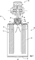
- a housing 12 and a filter element 14 are provided in connection with the fuel filter cartridge 10 disclosed herein.
- the filter element 14 is configured to create an improved connection between the cartridge 12 and element 14, in addition to simplifying the cartridge manufacturing process.
- the filter element 14 When completely installed, the filter element 14 is suspended within the cartridge housing 12. First (upper) and second (lower) cartridge shell portions (16 and 18 respectively) of the cartridge housing are connected after the filter element 14 is installed within the housing 12, to form a complete filter cartridge 10.
- the first shell portion 16 is a unitary housing which extends the length of the filter cartridge.
- a second shell portion 18 is attached at an end opposite a cartridge housing opening 20.
- the first shell portion 16 is attached to the second shell portion 18 at a joint 21.
- the joint 21 of the embodiment is intermediate the opening 20 and a base 23 of the second shell portion.
- the opening 20 in the first shell portion is located on a longitudinal axis of the cartridge.
- the opening 20 and first shell portion 16 may be configured to be compatible with any number of fuel filtration system mounts.
- An annular element retention lip 22 extends axially inward from the opening 20. As shown in Figures 1 and 2 , in one embodiment of the fuel filter cartridge, the lip 22 projects radially toward a longitudinal axis A-A of the filter cartridge. In an alternate embodiment illustrated in Figures 3-7 , the lip 22 projects radially away from a longitudinal axis of the first (upper) end cap B-B. As discussed below, the annular element retention lip 22 works in concert with a first end cap to suspend the filter element 14 within the housing 12.
- a continuous ring of filter media 27 extends between first (upper) and second (lower) end caps of the filter element (24 and 26 respectively).
- the filter media 27 may be constructed of cellulose paper or any other permeate fibrous material.
- the first end cap 24 mechanically connects the filter element 14 to the fuel filter housing 12.
- a main body portion 28 of the first end cap is depicted surrounding a fuel flow port 30, which is located on the longitudinal axis B-B.
- the fuel flow port 30 is configured as a receptacle to receive a fuel outlet conduit 31, thus allowing fuel to exit the fuel filter cartridge 10.
- filter media retention arms 32 project axially from the main body portion 28 of the first end cap 24 at the perimeter of the fuel flow port 30.
- the set of filter element retention arms 32 surround the fuel flow port 30 in a circle coaxial with the longitudinal axes of the filter cartridge A-A and first (upper) end cap B-B.
- the characteristics of the filter media retention arms 32 may be adapted to ensure a more secure connection. As one of skill in the art will appreciate, increasing the width of the arms 32, increasing the thickness of the arms 32, or multiplying the number of arms 32 will increase the retention force the arms can exert on the retention lip 22.
- Filter element retention barbs 34 project radially from the terminal end of the filter media retention arms 32.
- the barbs have an engagement ramp 36 oriented towards the annular lip 22 of the first shell 16 of the cartridge housing 12. Proceeding from the terminal end of the arms 34 and moving towards the main body portion 28, the barbs 34 increase in width while traveling along the engagement ramp 36. At the end of the engagement ramp 36 nearest the main body the barbs 34 terminate in a retention ledge 38.
- the ledge 38 shown in the figures is a flat surface that projects radially away from a surface of the arms 32 and abuts the engagement ramp 36.
- the characteristics of the ledge 38 and the annular lip 22 of the housing 12 may be altered to provide a more secure connection to the cartridge housing 12 in higher pressure filtration environments. For example, increasing the length of the ledge 38 and the radial width of the annular lip 22 will increase the retention forces exerted by the barbs 34 on the retention lip 22.
- the barbs 34 may be located on the surface of the retention arms 32 oriented towards a longitudinal axis B-B of the first end cap 24.
- the ledge 38 projects radially toward the longitudinal axis B-B of the first end cap 24.
- the barbs 34 are located on the surface of the arms 32 oriented away from longitudinal axis of the cartridge housing A-A.
- the alternate embodiments of the cartridge housing lip 22 are configured to cooperate with the alternate embodiments of the barbs 34.
- the embodiment of the housing where the lip 22 extends radially outwardly mates with the embodiment of the filter element where the ledge 38 extends radially inwardly, as shown in Figure 4 .
- the embodiment of the cartridge in which the lip 22 extends radially inwardly mates with the embodiment of the filter element in which the ledge 38 extends radially outwardly, as shown in Figures 1 and 2 .
- a plurality of support ribs 40 extend radially from the filter media retention arms.
- the support ribs 40 are connected to a surface of the arms 32 facing away from the fuel flow port 30 and provide biasing forces to aid in retention of the filter element 14 within the cartridge housing 12.
- the support ribs exert forces biasing the arms toward the longitudinal axis B-B.
- the ribs 40 ensure that the first end cap 28 is centered within the first shell portion 16. By extending to the perimeter of the main body 28, the ribs 40 abut the first shell portion 16 when installed, preventing the first end cap 24 from moving from side to side within the cartridge housing 12.
- the ribs 40 also act to define a plurality of fuel flow pathways 42.
- the ribs 40 extend to the periphery of main body portion 28 and abut the inside surface of the first shell portion 16.
- the ribs 40 are axially raised from the main body portion 28, creating a gap between the main body 28 and the first shell portion 16 of the cartridge housing.
- the ribs 40 define fuel flow paths extending radially outwardly across the main body of the first end cap.
- the embodiment of the filter cartridge 10 depicted in Fig. 4 is different, however, in that the ribs 40 aid in channeling fuel across the main body portion 28.
- the ribs 40 channel incoming fuel from the header (not shown) into the gap created between the main body 28 and the inside surface of the first shell portion 16.
- the ribs 40 channel unfiltered fuel around the periphery of the main body portion 28 and into the second shell portion (not shown).
- the fuel flows radially inwardly through the filter element (not shown).
- the filter media 26 removes water and abrasive particles, fuel flows axially toward the outlet conduit (not shown) and exits the cartridge.
- the configuration of the first end cap 24 and the first shell portion 16 facilitates assembly of fuel filter cartridges.
- the resilient filter element retention arms 32 provide a biasing spring-effect against the annular lip 22.
- the engagement ramps 36 of the filter element retention barbs 34 ride along the annular lip 22, radially flexing the retention arms 32 away from the annular lip 22.
- the biasing force of the retention arms 32 snap the barbs 34 into place, seating the retention ledge 38 of the filter element retention barbs 34 against the annular lip 22.
- the support ribs 40 discussed above may provide additional biasing forces to facilitate installation and retention of the filter element 14 within the cartridge housing 12.
Landscapes
- Chemical & Material Sciences (AREA)
- Chemical Kinetics & Catalysis (AREA)
- Filtration Of Liquid (AREA)
Claims (9)
- Élément de filtre ayant un axe longitudinal comprenant :un premier capuchon d'extrémité (24) ayant une partie corps principal (28), ledit corps principal (28) définissant un orifice d'écoulement de carburant (30) coaxial audit axe longitudinal, et une pluralité de bras de retenue (32) d'élément de filtre élastiques s'étendant axialement depuis ladite partie corps principal (28) et entourant ledit orifice d'écoulement de carburant (30), lesdits bras de retenue (32) étant terminés dans des crans de retenue (34),un second capuchon d'extrémité (26), etun anneau continu de matériau filtrant (27) ayant une extrémité fixée audit premier capuchon d'extrémité (24) et une extrémité opposée fixée audit second capuchon d'extrémité (26), caractérisé en ce quedes nervures de support (40) s'étendent radialement vers l'extérieur à partir desdits bras de retenue (32) d'élément de filtre élastiques jusqu'à un périmètre dudit premier capuchon d'extrémité (24), lesdites nervures de support (40) définissant une pluralité de passages d'écoulement de carburant (42) dirigeant le carburant radialement vers l'extérieur depuis ledit orifice d'écoulement de carburant (30).
- Élément de filtre selon la revendication 1, lesdits bras de retenue (32) d'élément de filtre élastiques ayant une surface intérieure et une surface extérieure, ladite surface intérieure comprenant la surface desdits bras (32) tournée vers ledit orifice d'écoulement de carburant (30) et ledit axe longitudinal, ladite surface extérieure comprenant la surface desdits bras (32) tournée à l'opposé dudit orifice d'écoulement de carburant (30) et dudit axe, et lesdits crans de retenue (34) d'élément de filtre étant situés sur la surface intérieure desdits bras (32) et faisant saillie vers ledit axe.
- Élément de filtre selon la revendication 1, lesdits bras de retenue (32) d'élément de filtre élastiques ayant une surface intérieure et une surface extérieure, ladite surface intérieure comprenant la surface desdits bras (32) tournée vers ledit orifice d'écoulement de carburant (30) et ledit axe longitudinal, ladite surface extérieure comprenant la surface desdits bras (32) tournée à l'opposé dudit orifice d'écoulement de carburant (30) et dudit axe, et lesdits crans de retenue (34) d'élément de filtre étant situés sur la surface extérieure desdits bras (32) et faisant saillie à l'opposé dudit axe.
- Cartouche de filtre ayant un axe longitudinal comprenant :un boîtier de cartouche (12) ayant des première et second parties coques (16, 18), ladite première partie coque (16) ayant une ouverture (20) de boîtier de cartouche et une lèvre de retenue (22) d'élément annulaire disposée axialement vers l'intérieur de ladite ouverture (20) et coaxiale audit axe longitudinal ;un élément de filtre (14) ayant un premier capuchon d'extrémité (24), un second capuchon d'extrémité (26) et un anneau continu de matériau filtrant (27) disposé entre lesdits premier et second capuchons d'extrémité (24, 26), ledit premier capuchon d'extrémité (24) ayant une partie corps principal (28) définissant un orifice d'écoulement de carburant (30) coaxial audit axe,le premier capuchon d'extrémité (24) ayant en outre une pluralité de bras de retenue (32) d'élément élastiques s'étendant axialement à partir dudit premier capuchon d'extrémité (24) et entourant ledit orifice d'écoulement de carburant (30), lesdits bras (32) se terminant dans des crans de retenue (34) pouvant être accouplés avec ladite lèvre annulaire (22),lesdits bras de retenue élastiques (32) maintenant lesdits crans de retenue (34) contre ladite lèvre annulaire (22) suspendant ledit élément de filtre (14) dans ledit boîtier de cartouche (12), caractérisée en ce quedes nervures de support (40) s'étendent radialement vers l'extérieur à partir desdits bras de retenue (32) d'élément de filtre élastiques jusqu'à un périmètre dudit premier capuchon d'extrémité (24), lesdites nervures de support (40) définissant au moins un passage d'écoulement de carburant (42) dirigeant le carburant radialement vers l'extérieur depuis ledit orifice d'écoulement de carburant (30).
- Cartouche de filtre selon la revendication 4, lesdits bras de retenue (32) d'élément élastiques ayant une surface intérieure et une surface extérieure, ladite surface intérieure comprenant la surface desdits bras (32) tournée vers ledit orifice d'écoulement de carburant (30), ladite surface extérieure comprenant la surface desdits bras (32) tournée à l'opposé dudit orifice d'écoulement de carburant (30), ladite lèvre annulaire (22) faisant saillie d'un axe central de ladite ouverture (20) de boîtier de cartouche, et lesdits crans de retenue (34) étant sur la surface intérieure desdits bras (32).
- Cartouche de filtre selon la revendication 4, lesdits bras de retenue (32) d'élément élastiques ayant une surface intérieure et une surface extérieure, ladite surface intérieure comprenant la surface desdits bras (32) tournée vers ledit orifice d'écoulement de carburant (30), ladite surface extérieure comprenant la surface desdits bras (32) tournée à l'opposé dudit orifice d'écoulement de carburant (30), ladite lèvre annulaire (22) faisant saillie vers un axe central de ladite ouverture (20) de boîtier de cartouche, et lesdits crans de retenue (34) étant sur la surface extérieure desdits bras (32).
- Cartouche de filtre selon la revendication 4, lesdites nervures de support (40) définissant une pluralité de passages d'écoulement de carburant dirigeant le carburant radialement vers l'extérieur depuis ledit orifice d'écoulement de carburant (30).
- Cartouche de filtre selon la revendication 4, lesdits crans (34) ayant une rampe de mise en prise (36) faisant face à ladite lèvre (22), ladite rampe de mise en prise (36) augmentant généralement en épaisseur progressant de l'extrémité des bras de retenue (32) vers la partie corps principal (28), et un rebord de mise en prise (38) venant en butée contre ladite rampe de mise en prise (36), ledit rebord de mise en prise (38) se terminant au niveau desdits bras de retenue (32).
- Procédé de fabrication d'une cartouche de filtre à carburant (10) selon la revendication 4, caractérisé par les étapes consistant à :fournir un boîtier de cartouche de filtre à carburant (12) ayant des première et seconde coques de boîtier (16, 18), ladite première coque (16) ayant une ouverture (20) de boîtier de cartouche et une lèvre de retenue d'élément annulaire (22) disposée axialement à l'intérieur de ladite ouverture (20) ;fournir l'élément de filtre (14) selon la revendication 1, lesdits crans de retenue (34) ayant une rampe de mise en prise (36) et un rebord de mise en prise (38) ;fixer ledit élément de filtre (14) sur ladite première coque (16) en faisant avancer ledit premier capuchon d'extrémité (24) vers ladite première coque (16), ladite rampe de mise en prise (36) desdits crans (34) passant par-dessus ladite lèvre (22) tout en faisant avancer ledit premier capuchon d'extrémité (24), et enclenchant lesdits crans (34) dans ladite lèvre (22) lorsque la rampe de mise en prise (36) passe la lèvre (22) maintenant ledit rebord (38) contre ladite lèvre (36).
Applications Claiming Priority (2)
| Application Number | Priority Date | Filing Date | Title |
|---|---|---|---|
| US13/371,562 US9067156B2 (en) | 2012-02-13 | 2012-02-13 | Filter cartridge assembly and method of manufacture thereof |
| PCT/US2012/028468 WO2013122612A1 (fr) | 2012-02-13 | 2012-03-09 | Ensemble à cartouche de filtre et procédé de fabrication de celui-ci |
Publications (3)
| Publication Number | Publication Date |
|---|---|
| EP2815120A1 EP2815120A1 (fr) | 2014-12-24 |
| EP2815120A4 EP2815120A4 (fr) | 2015-12-09 |
| EP2815120B1 true EP2815120B1 (fr) | 2019-08-07 |
Family
ID=48944736
Family Applications (1)
| Application Number | Title | Priority Date | Filing Date |
|---|---|---|---|
| EP12868540.1A Active EP2815120B1 (fr) | 2012-02-13 | 2012-03-09 | Ensemble à cartouche de filtre et procédé de fabrication de celui-ci |
Country Status (5)
| Country | Link |
|---|---|
| US (1) | US9067156B2 (fr) |
| EP (1) | EP2815120B1 (fr) |
| ES (1) | ES2749662T3 (fr) |
| IN (1) | IN2014MN01634A (fr) |
| WO (1) | WO2013122612A1 (fr) |
Families Citing this family (9)
| Publication number | Priority date | Publication date | Assignee | Title |
|---|---|---|---|---|
| US10195548B2 (en) | 2014-08-08 | 2019-02-05 | Clarcor Engine Mobile Solutions, Llc | Filter cartridge with integral lock ring |
| USD751170S1 (en) * | 2014-09-17 | 2016-03-08 | Rapid Pure, Inc. | Water filter mount assembly |
| AU2015376292B2 (en) * | 2015-01-07 | 2021-02-25 | Brita Se | Liquid treatment cartridge, set of such cartridges and method of manufacturing it |
| DE102015207231B4 (de) * | 2015-04-21 | 2017-09-14 | Mahle International Gmbh | Filtereinrichtung |
| EP3519075A4 (fr) | 2016-10-03 | 2020-05-27 | Parker-Hannifin Corporation | Élément de filtre avec verrou de torsion et ensemble |
| EP3551315B1 (fr) * | 2016-12-06 | 2022-06-08 | MANN+HUMMEL GmbH | Disque d'extrémité, élément filtre à disque d'extrémité et système de filtration |
| CN110769913B (zh) | 2017-05-31 | 2021-11-16 | 帕克-汉尼芬公司 | 带有扭锁和/或滑动活塞的过滤元件、组件和方法 |
| EP3441123B1 (fr) | 2017-08-11 | 2020-06-24 | Donaldson Company, Inc. | Dispositif de traitement de fluide amovible et procé?dé?s |
| DE102022209325A1 (de) * | 2022-09-07 | 2024-03-07 | Filtration Group Gmbh | Filterelement und Filtereinrichtung |
Family Cites Families (11)
| Publication number | Priority date | Publication date | Assignee | Title |
|---|---|---|---|---|
| US5985144A (en) | 1997-07-03 | 1999-11-16 | Stanadyne Automotive Corp. | Reverse flow cartridge |
| EP1008375A1 (fr) | 1998-12-11 | 2000-06-14 | Baldwin Filters, Inc. | Ensemble de filtre à carburant et couvercle jetable |
| US6187188B1 (en) | 1999-07-19 | 2001-02-13 | Stanadyne Automotive Corp. | Filter cartridge retention system |
| JP2006517864A (ja) | 2003-01-28 | 2006-08-03 | ドナルドソン カンパニー,インコーポレイティド | 濾過組立体及び濾過方法 |
| WO2005005014A1 (fr) * | 2003-07-01 | 2005-01-20 | Parker-Hannifin Corporation | Ensemble de filtre a filetage coulissant |
| WO2006023748A2 (fr) | 2004-08-20 | 2006-03-02 | Stanadyne Corporation | Filtre a carburant a ecoulement inverse |
| US7882961B2 (en) | 2005-11-01 | 2011-02-08 | Cummins Filtration Ip, Inc. | Replaceable fuel filter element and fuel filter assembly |
| US20070227963A1 (en) * | 2006-03-31 | 2007-10-04 | Baldwin Filters, Inc. | Fluid filter element and bypass adaptor |
| WO2007140247A2 (fr) | 2006-05-24 | 2007-12-06 | Parker-Hannifin Corporation | Élément de filtre à écoulement triple avec purge |
| JP4984271B2 (ja) * | 2006-09-05 | 2012-07-25 | ポール・コーポレーション | フィルタエレメントおよび組立体 |
| CN201099628Y (zh) * | 2007-09-30 | 2008-08-13 | 周奇迪 | 一种管道式净水器及管道式净水器快速接头 |
-
2012
- 2012-02-13 US US13/371,562 patent/US9067156B2/en active Active
- 2012-02-13 IN IN1634MUN2014 patent/IN2014MN01634A/en unknown
- 2012-03-09 ES ES12868540T patent/ES2749662T3/es active Active
- 2012-03-09 EP EP12868540.1A patent/EP2815120B1/fr active Active
- 2012-03-09 WO PCT/US2012/028468 patent/WO2013122612A1/fr active Application Filing
Non-Patent Citations (1)
| Title |
|---|
| None * |
Also Published As
| Publication number | Publication date |
|---|---|
| EP2815120A4 (fr) | 2015-12-09 |
| WO2013122612A1 (fr) | 2013-08-22 |
| EP2815120A1 (fr) | 2014-12-24 |
| ES2749662T3 (es) | 2020-03-23 |
| US9067156B2 (en) | 2015-06-30 |
| US20130206680A1 (en) | 2013-08-15 |
| IN2014MN01634A (fr) | 2015-05-15 |
Similar Documents
| Publication | Publication Date | Title |
|---|---|---|
| EP2815120B1 (fr) | Ensemble à cartouche de filtre et procédé de fabrication de celui-ci | |
| EP3055548B1 (fr) | Elément filtrant avec scellage ondulé | |
| US11318398B2 (en) | Coalescing filter element | |
| US7662216B1 (en) | In-line filter and service method | |
| EP2135658B1 (fr) | Filtre de fluide et ensemble de filtre de fluide | |
| EP3250305B1 (fr) | Ensemble filtre comprenant un capuchon d'écoulement | |
| EP3250304B1 (fr) | Bouchon de coupure de flux et procédé pour l'envoi d'un fluide dans un filtre | |
| US20190240602A1 (en) | Facial sealing system for a filter | |
| WO2015050540A1 (fr) | Cartouche de filtre à carburant et procédé d'utilisation de cette dernière | |
| US20180200652A1 (en) | Filter Element With Offset Fluid Passage | |
| KR20080004479A (ko) | 개선된 디젤 연료 필터 | |
| CN109843409B (zh) | 过滤器组件的碗体 | |
| US20080179235A1 (en) | Fluid Filter Arrangement and Method | |
| EP3906108B9 (fr) | Élément d'étanchéité d'embout d'extrémité multifonctionnel intégré | |
| US10195548B2 (en) | Filter cartridge with integral lock ring | |
| WO2018136047A1 (fr) | Élément filtrant à passage de fluide décentré | |
| EP3427804A1 (fr) | Bol d'eau à indexage radial et profil bas comportant connecteur wi-fi intégré | |
| CN116710186A (zh) | 带疏水滤网的多级过滤器 |
Legal Events
| Date | Code | Title | Description |
|---|---|---|---|
| PUAI | Public reference made under article 153(3) epc to a published international application that has entered the european phase |
Free format text: ORIGINAL CODE: 0009012 |
|
| 17P | Request for examination filed |
Effective date: 20140909 |
|
| AK | Designated contracting states |
Kind code of ref document: A1 Designated state(s): AL AT BE BG CH CY CZ DE DK EE ES FI FR GB GR HR HU IE IS IT LI LT LU LV MC MK MT NL NO PL PT RO RS SE SI SK SM TR |
|
| AX | Request for extension of the european patent |
Extension state: BA ME |
|
| DAX | Request for extension of the european patent (deleted) | ||
| RA4 | Supplementary search report drawn up and despatched (corrected) |
Effective date: 20151105 |
|
| RIC1 | Information provided on ipc code assigned before grant |
Ipc: B01D 27/08 20060101ALI20151030BHEP Ipc: F02M 37/22 20060101AFI20151030BHEP Ipc: B01D 35/30 20060101ALI20151030BHEP |
|
| STAA | Information on the status of an ep patent application or granted ep patent |
Free format text: STATUS: EXAMINATION IS IN PROGRESS |
|
| 17Q | First examination report despatched |
Effective date: 20170920 |
|
| GRAP | Despatch of communication of intention to grant a patent |
Free format text: ORIGINAL CODE: EPIDOSNIGR1 |
|
| STAA | Information on the status of an ep patent application or granted ep patent |
Free format text: STATUS: GRANT OF PATENT IS INTENDED |
|
| INTG | Intention to grant announced |
Effective date: 20190313 |
|
| GRAS | Grant fee paid |
Free format text: ORIGINAL CODE: EPIDOSNIGR3 |
|
| GRAA | (expected) grant |
Free format text: ORIGINAL CODE: 0009210 |
|
| STAA | Information on the status of an ep patent application or granted ep patent |
Free format text: STATUS: THE PATENT HAS BEEN GRANTED |
|
| AK | Designated contracting states |
Kind code of ref document: B1 Designated state(s): AL AT BE BG CH CY CZ DE DK EE ES FI FR GB GR HR HU IE IS IT LI LT LU LV MC MK MT NL NO PL PT RO RS SE SI SK SM TR |
|
| REG | Reference to a national code |
Ref country code: GB Ref legal event code: FG4D |
|
| REG | Reference to a national code |
Ref country code: CH Ref legal event code: EP Ref country code: AT Ref legal event code: REF Ref document number: 1164265 Country of ref document: AT Kind code of ref document: T Effective date: 20190815 |
|
| REG | Reference to a national code |
Ref country code: DE Ref legal event code: R096 Ref document number: 602012062825 Country of ref document: DE |
|
| REG | Reference to a national code |
Ref country code: IE Ref legal event code: FG4D |
|
| REG | Reference to a national code |
Ref country code: NL Ref legal event code: MP Effective date: 20190807 |
|
| REG | Reference to a national code |
Ref country code: LT Ref legal event code: MG4D |
|
| PG25 | Lapsed in a contracting state [announced via postgrant information from national office to epo] |
Ref country code: NO Free format text: LAPSE BECAUSE OF FAILURE TO SUBMIT A TRANSLATION OF THE DESCRIPTION OR TO PAY THE FEE WITHIN THE PRESCRIBED TIME-LIMIT Effective date: 20191107 Ref country code: FI Free format text: LAPSE BECAUSE OF FAILURE TO SUBMIT A TRANSLATION OF THE DESCRIPTION OR TO PAY THE FEE WITHIN THE PRESCRIBED TIME-LIMIT Effective date: 20190807 Ref country code: HR Free format text: LAPSE BECAUSE OF FAILURE TO SUBMIT A TRANSLATION OF THE DESCRIPTION OR TO PAY THE FEE WITHIN THE PRESCRIBED TIME-LIMIT Effective date: 20190807 Ref country code: LT Free format text: LAPSE BECAUSE OF FAILURE TO SUBMIT A TRANSLATION OF THE DESCRIPTION OR TO PAY THE FEE WITHIN THE PRESCRIBED TIME-LIMIT Effective date: 20190807 Ref country code: SE Free format text: LAPSE BECAUSE OF FAILURE TO SUBMIT A TRANSLATION OF THE DESCRIPTION OR TO PAY THE FEE WITHIN THE PRESCRIBED TIME-LIMIT Effective date: 20190807 Ref country code: BG Free format text: LAPSE BECAUSE OF FAILURE TO SUBMIT A TRANSLATION OF THE DESCRIPTION OR TO PAY THE FEE WITHIN THE PRESCRIBED TIME-LIMIT Effective date: 20191107 Ref country code: NL Free format text: LAPSE BECAUSE OF FAILURE TO SUBMIT A TRANSLATION OF THE DESCRIPTION OR TO PAY THE FEE WITHIN THE PRESCRIBED TIME-LIMIT Effective date: 20190807 Ref country code: PT Free format text: LAPSE BECAUSE OF FAILURE TO SUBMIT A TRANSLATION OF THE DESCRIPTION OR TO PAY THE FEE WITHIN THE PRESCRIBED TIME-LIMIT Effective date: 20191209 |
|
| REG | Reference to a national code |
Ref country code: AT Ref legal event code: MK05 Ref document number: 1164265 Country of ref document: AT Kind code of ref document: T Effective date: 20190807 |
|
| PG25 | Lapsed in a contracting state [announced via postgrant information from national office to epo] |
Ref country code: GR Free format text: LAPSE BECAUSE OF FAILURE TO SUBMIT A TRANSLATION OF THE DESCRIPTION OR TO PAY THE FEE WITHIN THE PRESCRIBED TIME-LIMIT Effective date: 20191108 Ref country code: AL Free format text: LAPSE BECAUSE OF FAILURE TO SUBMIT A TRANSLATION OF THE DESCRIPTION OR TO PAY THE FEE WITHIN THE PRESCRIBED TIME-LIMIT Effective date: 20190807 Ref country code: RS Free format text: LAPSE BECAUSE OF FAILURE TO SUBMIT A TRANSLATION OF THE DESCRIPTION OR TO PAY THE FEE WITHIN THE PRESCRIBED TIME-LIMIT Effective date: 20190807 Ref country code: IS Free format text: LAPSE BECAUSE OF FAILURE TO SUBMIT A TRANSLATION OF THE DESCRIPTION OR TO PAY THE FEE WITHIN THE PRESCRIBED TIME-LIMIT Effective date: 20191207 Ref country code: LV Free format text: LAPSE BECAUSE OF FAILURE TO SUBMIT A TRANSLATION OF THE DESCRIPTION OR TO PAY THE FEE WITHIN THE PRESCRIBED TIME-LIMIT Effective date: 20190807 |
|
| REG | Reference to a national code |
Ref country code: ES Ref legal event code: FG2A Ref document number: 2749662 Country of ref document: ES Kind code of ref document: T3 Effective date: 20200323 |
|
| PG25 | Lapsed in a contracting state [announced via postgrant information from national office to epo] |
Ref country code: RO Free format text: LAPSE BECAUSE OF FAILURE TO SUBMIT A TRANSLATION OF THE DESCRIPTION OR TO PAY THE FEE WITHIN THE PRESCRIBED TIME-LIMIT Effective date: 20190807 Ref country code: AT Free format text: LAPSE BECAUSE OF FAILURE TO SUBMIT A TRANSLATION OF THE DESCRIPTION OR TO PAY THE FEE WITHIN THE PRESCRIBED TIME-LIMIT Effective date: 20190807 Ref country code: PL Free format text: LAPSE BECAUSE OF FAILURE TO SUBMIT A TRANSLATION OF THE DESCRIPTION OR TO PAY THE FEE WITHIN THE PRESCRIBED TIME-LIMIT Effective date: 20190807 Ref country code: DK Free format text: LAPSE BECAUSE OF FAILURE TO SUBMIT A TRANSLATION OF THE DESCRIPTION OR TO PAY THE FEE WITHIN THE PRESCRIBED TIME-LIMIT Effective date: 20190807 Ref country code: EE Free format text: LAPSE BECAUSE OF FAILURE TO SUBMIT A TRANSLATION OF THE DESCRIPTION OR TO PAY THE FEE WITHIN THE PRESCRIBED TIME-LIMIT Effective date: 20190807 |
|
| PG25 | Lapsed in a contracting state [announced via postgrant information from national office to epo] |
Ref country code: CZ Free format text: LAPSE BECAUSE OF FAILURE TO SUBMIT A TRANSLATION OF THE DESCRIPTION OR TO PAY THE FEE WITHIN THE PRESCRIBED TIME-LIMIT Effective date: 20190807 Ref country code: SM Free format text: LAPSE BECAUSE OF FAILURE TO SUBMIT A TRANSLATION OF THE DESCRIPTION OR TO PAY THE FEE WITHIN THE PRESCRIBED TIME-LIMIT Effective date: 20190807 Ref country code: IS Free format text: LAPSE BECAUSE OF FAILURE TO SUBMIT A TRANSLATION OF THE DESCRIPTION OR TO PAY THE FEE WITHIN THE PRESCRIBED TIME-LIMIT Effective date: 20200224 Ref country code: SK Free format text: LAPSE BECAUSE OF FAILURE TO SUBMIT A TRANSLATION OF THE DESCRIPTION OR TO PAY THE FEE WITHIN THE PRESCRIBED TIME-LIMIT Effective date: 20190807 |
|
| REG | Reference to a national code |
Ref country code: DE Ref legal event code: R097 Ref document number: 602012062825 Country of ref document: DE |
|
| PLBE | No opposition filed within time limit |
Free format text: ORIGINAL CODE: 0009261 |
|
| STAA | Information on the status of an ep patent application or granted ep patent |
Free format text: STATUS: NO OPPOSITION FILED WITHIN TIME LIMIT |
|
| PG2D | Information on lapse in contracting state deleted |
Ref country code: IS |
|
| 26N | No opposition filed |
Effective date: 20200603 |
|
| PG25 | Lapsed in a contracting state [announced via postgrant information from national office to epo] |
Ref country code: SI Free format text: LAPSE BECAUSE OF FAILURE TO SUBMIT A TRANSLATION OF THE DESCRIPTION OR TO PAY THE FEE WITHIN THE PRESCRIBED TIME-LIMIT Effective date: 20190807 |
|
| PG25 | Lapsed in a contracting state [announced via postgrant information from national office to epo] |
Ref country code: MC Free format text: LAPSE BECAUSE OF FAILURE TO SUBMIT A TRANSLATION OF THE DESCRIPTION OR TO PAY THE FEE WITHIN THE PRESCRIBED TIME-LIMIT Effective date: 20190807 |
|
| REG | Reference to a national code |
Ref country code: CH Ref legal event code: PL |
|
| REG | Reference to a national code |
Ref country code: BE Ref legal event code: MM Effective date: 20200331 |
|
| PG25 | Lapsed in a contracting state [announced via postgrant information from national office to epo] |
Ref country code: LU Free format text: LAPSE BECAUSE OF NON-PAYMENT OF DUE FEES Effective date: 20200309 |
|
| PG25 | Lapsed in a contracting state [announced via postgrant information from national office to epo] |
Ref country code: LI Free format text: LAPSE BECAUSE OF NON-PAYMENT OF DUE FEES Effective date: 20200331 Ref country code: CH Free format text: LAPSE BECAUSE OF NON-PAYMENT OF DUE FEES Effective date: 20200331 Ref country code: IE Free format text: LAPSE BECAUSE OF NON-PAYMENT OF DUE FEES Effective date: 20200309 |
|
| PG25 | Lapsed in a contracting state [announced via postgrant information from national office to epo] |
Ref country code: BE Free format text: LAPSE BECAUSE OF NON-PAYMENT OF DUE FEES Effective date: 20200331 |
|
| PG25 | Lapsed in a contracting state [announced via postgrant information from national office to epo] |
Ref country code: MT Free format text: LAPSE BECAUSE OF FAILURE TO SUBMIT A TRANSLATION OF THE DESCRIPTION OR TO PAY THE FEE WITHIN THE PRESCRIBED TIME-LIMIT Effective date: 20190807 Ref country code: CY Free format text: LAPSE BECAUSE OF FAILURE TO SUBMIT A TRANSLATION OF THE DESCRIPTION OR TO PAY THE FEE WITHIN THE PRESCRIBED TIME-LIMIT Effective date: 20190807 |
|
| PG25 | Lapsed in a contracting state [announced via postgrant information from national office to epo] |
Ref country code: MK Free format text: LAPSE BECAUSE OF FAILURE TO SUBMIT A TRANSLATION OF THE DESCRIPTION OR TO PAY THE FEE WITHIN THE PRESCRIBED TIME-LIMIT Effective date: 20190807 |
|
| PGFP | Annual fee paid to national office [announced via postgrant information from national office to epo] |
Ref country code: FR Payment date: 20230327 Year of fee payment: 12 |
|
| PGFP | Annual fee paid to national office [announced via postgrant information from national office to epo] |
Ref country code: TR Payment date: 20230223 Year of fee payment: 12 Ref country code: IT Payment date: 20230321 Year of fee payment: 12 |
|
| P01 | Opt-out of the competence of the unified patent court (upc) registered |
Effective date: 20230524 |
|
| PGFP | Annual fee paid to national office [announced via postgrant information from national office to epo] |
Ref country code: ES Payment date: 20230403 Year of fee payment: 12 |
|
| PGFP | Annual fee paid to national office [announced via postgrant information from national office to epo] |
Ref country code: DE Payment date: 20240327 Year of fee payment: 13 Ref country code: GB Payment date: 20240327 Year of fee payment: 13 |