EP2815120B1 - Filter cartridge assembly and method of manufacture thereof - Google Patents
Filter cartridge assembly and method of manufacture thereof Download PDFInfo
- Publication number
- EP2815120B1 EP2815120B1 EP12868540.1A EP12868540A EP2815120B1 EP 2815120 B1 EP2815120 B1 EP 2815120B1 EP 12868540 A EP12868540 A EP 12868540A EP 2815120 B1 EP2815120 B1 EP 2815120B1
- Authority
- EP
- European Patent Office
- Prior art keywords
- arms
- retention
- fuel
- end cap
- filter element
- Prior art date
- Legal status (The legal status is an assumption and is not a legal conclusion. Google has not performed a legal analysis and makes no representation as to the accuracy of the status listed.)
- Active
Links
- 238000000034 method Methods 0.000 title claims description 4
- 238000004519 manufacturing process Methods 0.000 title description 5
- 239000000446 fuel Substances 0.000 claims description 75
- 230000014759 maintenance of location Effects 0.000 claims description 52
- 230000037361 pathway Effects 0.000 claims description 4
- 230000002250 progressing effect Effects 0.000 claims 1
- XLYOFNOQVPJJNP-UHFFFAOYSA-N water Substances O XLYOFNOQVPJJNP-UHFFFAOYSA-N 0.000 description 6
- 239000000853 adhesive Substances 0.000 description 5
- 230000001070 adhesive effect Effects 0.000 description 5
- 239000002245 particle Substances 0.000 description 5
- 238000001914 filtration Methods 0.000 description 4
- 239000012530 fluid Substances 0.000 description 3
- 239000002283 diesel fuel Substances 0.000 description 2
- 238000009434 installation Methods 0.000 description 2
- 229920002678 cellulose Polymers 0.000 description 1
- 239000001913 cellulose Substances 0.000 description 1
- 230000005465 channeling Effects 0.000 description 1
- 238000002485 combustion reaction Methods 0.000 description 1
- 239000000356 contaminant Substances 0.000 description 1
- 230000007613 environmental effect Effects 0.000 description 1
- 239000002657 fibrous material Substances 0.000 description 1
- 230000008014 freezing Effects 0.000 description 1
- 238000007710 freezing Methods 0.000 description 1
- 238000002347 injection Methods 0.000 description 1
- 239000007924 injection Substances 0.000 description 1
- 239000007788 liquid Substances 0.000 description 1
- 239000000463 material Substances 0.000 description 1
- 239000002184 metal Substances 0.000 description 1
- 239000012466 permeate Substances 0.000 description 1
- 238000011085 pressure filtration Methods 0.000 description 1
- 239000000047 product Substances 0.000 description 1
- 239000000243 solution Substances 0.000 description 1
- 239000002699 waste material Substances 0.000 description 1
Images


Classifications
-
- B—PERFORMING OPERATIONS; TRANSPORTING
- B01—PHYSICAL OR CHEMICAL PROCESSES OR APPARATUS IN GENERAL
- B01D—SEPARATION
- B01D29/00—Filters with filtering elements stationary during filtration, e.g. pressure or suction filters, not covered by groups B01D24/00 - B01D27/00; Filtering elements therefor
- B01D29/11—Filters with filtering elements stationary during filtration, e.g. pressure or suction filters, not covered by groups B01D24/00 - B01D27/00; Filtering elements therefor with bag, cage, hose, tube, sleeve or like filtering elements
- B01D29/13—Supported filter elements
- B01D29/15—Supported filter elements arranged for inward flow filtration
- B01D29/21—Supported filter elements arranged for inward flow filtration with corrugated, folded or wound sheets
-
- B—PERFORMING OPERATIONS; TRANSPORTING
- B01—PHYSICAL OR CHEMICAL PROCESSES OR APPARATUS IN GENERAL
- B01D—SEPARATION
- B01D2201/00—Details relating to filtering apparatus
- B01D2201/29—Filter cartridge constructions
- B01D2201/291—End caps
-
- B—PERFORMING OPERATIONS; TRANSPORTING
- B01—PHYSICAL OR CHEMICAL PROCESSES OR APPARATUS IN GENERAL
- B01D—SEPARATION
- B01D2201/00—Details relating to filtering apparatus
- B01D2201/30—Filter housing constructions
- B01D2201/301—Details of removable closures, lids, caps, filter heads
- B01D2201/305—Snap, latch or clip connecting means
-
- B—PERFORMING OPERATIONS; TRANSPORTING
- B01—PHYSICAL OR CHEMICAL PROCESSES OR APPARATUS IN GENERAL
- B01D—SEPARATION
- B01D2201/00—Details relating to filtering apparatus
- B01D2201/40—Special measures for connecting different parts of the filter
- B01D2201/4084—Snap or Seeger ring connecting means
-
- Y—GENERAL TAGGING OF NEW TECHNOLOGICAL DEVELOPMENTS; GENERAL TAGGING OF CROSS-SECTIONAL TECHNOLOGIES SPANNING OVER SEVERAL SECTIONS OF THE IPC; TECHNICAL SUBJECTS COVERED BY FORMER USPC CROSS-REFERENCE ART COLLECTIONS [XRACs] AND DIGESTS
- Y10—TECHNICAL SUBJECTS COVERED BY FORMER USPC
- Y10T—TECHNICAL SUBJECTS COVERED BY FORMER US CLASSIFICATION
- Y10T29/00—Metal working
- Y10T29/49—Method of mechanical manufacture
- Y10T29/49826—Assembling or joining
Landscapes
- Chemical & Material Sciences (AREA)
- Chemical Kinetics & Catalysis (AREA)
- Filtration Of Liquid (AREA)
Description
- This disclosure relates generally to devices for filtering and separating liquids. More particularly, the present invention relates to fuel filters for removing foreign particles and separating water from fuel in an internal combustion engine.
- It is well-documented that significant quantities of contaminants such as water and various abrasive particles are found in diesel fuel. In addition to corroding metal components, water may obstruct the fuel lines when environmental temperatures fall below freezing. Likewise, abrasive particles may damage sensitive engine components such as the fuel injection pump.
- Fuel filter cartridges are a well-known solution for removing water and abrasive particles from diesel fuel before the fuel is pumped into sensitive engine systems. Prior art fuel filter cartridges typically have a housing which defines an axial opening at one end thereof to provide fuel communication between the fuel delivery system and a filter element disposed within the cartridge housing. Customarily, the cartridge housing comprises two separate shell portions, one of which defines the axial opening. Filter elements typically comprise a ring of fuel filter media and a pair of end caps. The filter media typically comprises non-woven material, while one end cap is typically an imperforate cover to which one end of the fuel filter media is permanently affixed.
- Prior art filters are manufactured by affixing the ends of the filter media to first and second end caps. Typically the filter element is affixed to the shell portion defining the axial opening using an adhesive. After the adhesive cures, the filter cartridges are typically completed by joining the two shell portions. Use of adhesive to secure the filter element within the housing complicates cartridge manufacture. There is a need for a simple, robust means for securing a filter element within a cartridge housing. From
US 2007/0227963 A1 a fluid filter arrangement comprising a cartridge housing and a filter element is known. The filter element comprises first and second end caps, wherein the first end cap is affixed to the cartridge housing by means of an adaptor element. The adaptor element comprises a plurality of vertically extending prongs adapted to secure the adaptor element and filter element to the cartridge housing by engaging behind a lid of the housing. - Briefly stated, in one embodiment the current disclosure is an improved fuel filter element. The filter element has a longitudinal axis and comprises a first (upper) end cap, a second (lower) end cap, and a continuous ring of filter media attached between the two end caps. The first end cap has a main body portion, which defines a fuel flow port. The fuel flow port is coaxial with the longitudinal axis of the filter element. A plurality of resilient filter element retention arms extend axially from the main body portion axially opposite the filter media. The arms surround the fuel flow port, and terminate in retention barbs.
- Additionally, a filter cartridge housing is contemplated for use in connection with the improved fuel filter element disclosed herein. The cartridge housing also has a longitudinal axis and comprises first (upper) and second (lower) shell portions. The first shell portion has a cartridge housing opening and an annular element retention lip. The annular element retention lip is disposed axially inward of the opening of the cartridge housing and is coaxial with the cartridge's longitudinal axis.
- The fuel filter element is mounted within the cartridge housing by affixing the filter element to the first shell portion. The fuel filter element is affixed by advancing the first end cap towards the first shell portion. As the first end cap is brought towards the first shell portion, the barbs of the first end cap ride over the element retention lip. Once the barbs ride past the lip, the barbs snap into the lip and, along with the arms, suspend the filter element within the cartridge housing.
- The apparatus and method of the present disclosure provides advantages over and relative to the above discussed prior art. For example, the fuel filter element and associated filter cartridge disclosed herein provides reliable filtration of fuel, and a strong mechanical connection between the cartridge housing and filter element. The mechanical connection between the first end cap and the first shell portion provides strong retention forces, without the need for an adhesive connection between the element and the housing. Furthermore, the method of mounting the fuel filter element within the cartridge streamlines the cartridge manufacturing process and reduces the time required for assembly of a complete product. The disclosed configuration of the filter element and cartridge housing allows for complete pre-manufacture of the filter element before installation of the filter element into the housing, eliminating the use of adhesive within the housing. Other advantages and features of the present invention will become apparent to those skilled in the art from the following detailed description, from the claims, and from the accompanying drawings.
- The present disclosure may be better understood and its numerous objects and advantages will become apparent to those skilled in the art by reference to the accompanying drawings in which:
-
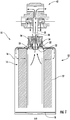
Fig. 1 is a cross-sectional view of one embodiment of the disclosed fuel filter cartridge shown with an accompanying fuel filter header; -
Fig. 2 is an enlarged cross-sectional view of the embodiment of the fuel filter depicted inFig. 1 ; -
Fig. 3 is a perspective view of an alternate embodiment of a first (upper) end cap of the disclosed filter element, the cartridge housing, second end cap, and filter media are omitted for clarity; -
Fig. 4 is a cross sectional view of the embodiment of the first end cap ofFig. 3 as configured when the first end cap is installed in an alternate embodiment of the first cartridge shell portion; the second shell portion, second end cap, and filter media are omitted for clarity; -
Fig. 5 is a close up of the embodiment of the filter cartridge first end cap depicted inFig. 4 ; the first shell portion, second shell portion, second end cap, and filter media are omitted for clarity; -
Fig. 6 is a perspective view of the embodiment of the first end cap and first shell portion ofFigs. 3-5 ; the second shell portion, second end cap, and filter media are omitted for clarity; and -
Fig. 7 is a cross sectional view of the embodiment of the first shell portion depicted inFig. 4 , further showing a second shell portion and a joint between the shell portions; a water waste outlet valve is additionally shown, while the filter element is omitted for clarity. - With reference to the drawings wherein like numerals represent like parts throughout the several figures, a
housing 12 and afilter element 14 are provided in connection with thefuel filter cartridge 10 disclosed herein. Thefilter element 14 is configured to create an improved connection between thecartridge 12 andelement 14, in addition to simplifying the cartridge manufacturing process. - When completely installed, the
filter element 14 is suspended within thecartridge housing 12. First (upper) and second (lower) cartridge shell portions (16 and 18 respectively) of the cartridge housing are connected after thefilter element 14 is installed within thehousing 12, to form acomplete filter cartridge 10. As shown inFig. 1 , in one embodiment thefirst shell portion 16 is a unitary housing which extends the length of the filter cartridge. Asecond shell portion 18 is attached at an end opposite a cartridge housing opening 20. In an alternate embodiment shown inFig. 7 , thefirst shell portion 16 is attached to thesecond shell portion 18 at ajoint 21. As shown inFig. 7 , thejoint 21 of the embodiment is intermediate the opening 20 and abase 23 of the second shell portion. - The opening 20 in the first shell portion is located on a longitudinal axis of the cartridge. The opening 20 and
first shell portion 16 may be configured to be compatible with any number of fuel filtration system mounts. An annularelement retention lip 22 extends axially inward from the opening 20. As shown inFigures 1 and2 , in one embodiment of the fuel filter cartridge, thelip 22 projects radially toward a longitudinal axis A-A of the filter cartridge. In an alternate embodiment illustrated inFigures 3-7 , thelip 22 projects radially away from a longitudinal axis of the first (upper) end cap B-B. As discussed below, the annularelement retention lip 22 works in concert with a first end cap to suspend thefilter element 14 within thehousing 12. - Referring to
Figs. 1 and2 , a continuous ring offilter media 27 extends between first (upper) and second (lower) end caps of the filter element (24 and 26 respectively). Thefilter media 27 may be constructed of cellulose paper or any other permeate fibrous material. As shown inFigs. 1 ,2 , and4 , thefirst end cap 24 mechanically connects thefilter element 14 to thefuel filter housing 12. Amain body portion 28 of the first end cap is depicted surrounding afuel flow port 30, which is located on the longitudinal axis B-B. Thefuel flow port 30 is configured as a receptacle to receive afuel outlet conduit 31, thus allowing fuel to exit thefuel filter cartridge 10. - As depicted in
Figs. 2-5 , filtermedia retention arms 32 project axially from themain body portion 28 of thefirst end cap 24 at the perimeter of thefuel flow port 30. The set of filterelement retention arms 32 surround thefuel flow port 30 in a circle coaxial with the longitudinal axes of the filter cartridge A-A and first (upper) end cap B-B. Depending on the pressure within the filtration environment, the characteristics of the filtermedia retention arms 32 may be adapted to ensure a more secure connection. As one of skill in the art will appreciate, increasing the width of thearms 32, increasing the thickness of thearms 32, or multiplying the number ofarms 32 will increase the retention force the arms can exert on theretention lip 22. - Filter
element retention barbs 34 project radially from the terminal end of the filtermedia retention arms 32. In the embodiment illustrated inFig. 5 , the barbs have anengagement ramp 36 oriented towards theannular lip 22 of thefirst shell 16 of thecartridge housing 12. Proceeding from the terminal end of thearms 34 and moving towards themain body portion 28, thebarbs 34 increase in width while traveling along theengagement ramp 36. At the end of theengagement ramp 36 nearest the main body thebarbs 34 terminate in aretention ledge 38. Theledge 38 shown in the figures is a flat surface that projects radially away from a surface of thearms 32 and abuts theengagement ramp 36. Like the arms, the characteristics of theledge 38 and theannular lip 22 of thehousing 12 may be altered to provide a more secure connection to thecartridge housing 12 in higher pressure filtration environments. For example, increasing the length of theledge 38 and the radial width of theannular lip 22 will increase the retention forces exerted by thebarbs 34 on theretention lip 22. - As shown in
Fig. 3 , thebarbs 34 may be located on the surface of theretention arms 32 oriented towards a longitudinal axis B-B of thefirst end cap 24. Thus, in this configuration, theledge 38 projects radially toward the longitudinal axis B-B of thefirst end cap 24. In an alternate embodiment depicted inFigs. 1 and2 , thebarbs 34 are located on the surface of thearms 32 oriented away from longitudinal axis of the cartridge housing A-A. The alternate embodiments of thecartridge housing lip 22 are configured to cooperate with the alternate embodiments of thebarbs 34. The embodiment of the housing where thelip 22 extends radially outwardly mates with the embodiment of the filter element where theledge 38 extends radially inwardly, as shown inFigure 4 . The embodiment of the cartridge in which thelip 22 extends radially inwardly mates with the embodiment of the filter element in which theledge 38 extends radially outwardly, as shown inFigures 1 and2 . - As shown in
Figures 3-6 , a plurality ofsupport ribs 40 extend radially from the filter media retention arms. Thesupport ribs 40 are connected to a surface of thearms 32 facing away from thefuel flow port 30 and provide biasing forces to aid in retention of thefilter element 14 within thecartridge housing 12. In the embodiment illustrated inFigs. 4 and5 , the support ribs exert forces biasing the arms toward the longitudinal axis B-B. Furthermore, in one embodiment where theribs 40 extend from thearms 32 to a perimeter of thefirst end cap 28, theribs 40 ensure that thefirst end cap 28 is centered within thefirst shell portion 16. By extending to the perimeter of themain body 28, theribs 40 abut thefirst shell portion 16 when installed, preventing thefirst end cap 24 from moving from side to side within thecartridge housing 12. - In the embodiment in which the
ribs 40 extend to the periphery of themain body portion 28, theribs 40 also act to define a plurality offuel flow pathways 42. For example, inFig. 4 theribs 40 extend to the periphery ofmain body portion 28 and abut the inside surface of thefirst shell portion 16. At the periphery, theribs 40 are axially raised from themain body portion 28, creating a gap between themain body 28 and thefirst shell portion 16 of the cartridge housing. Theribs 40 define fuel flow paths extending radially outwardly across the main body of the first end cap. - Fluid flow through the
filter cartridge 10 will now be described, where the fuel flow is indicated with arrows. In the embodiment of the filter cartridge depicted inFigs. 1 and2 , unfiltered fuel enters the cartridge from theheader 42. When installed, thefuel outlet conduit 31 of the header prevents unfiltered fuel from entering thefuel flow port 30. Fuel flows radially across themain body portion 28 through gaps in the filter media retention arms, and around the periphery of themain body portion 28. After flowing around the periphery, fuel flows radially inwardly through thefilter element 27, and axially toward thefuel outlet conduit 31. Fuel then flows intofuel outlet conduit 31, and exits theheader 42. - In the embodiment depicted in
Fig. 4 , fluid flows through thefilter cartridge 10 in a similar pattern to the path described in connection withFigs. 1 and2 . The embodiment of thefilter cartridge 10 depicted inFig. 4 is different, however, in that theribs 40 aid in channeling fuel across themain body portion 28. Theribs 40 channel incoming fuel from the header (not shown) into the gap created between themain body 28 and the inside surface of thefirst shell portion 16. Thus, theribs 40 channel unfiltered fuel around the periphery of themain body portion 28 and into the second shell portion (not shown). Once the fuel flows into the second shell portion (not shown), the fuel flows radially inwardly through the filter element (not shown). After the filter media 26 removes water and abrasive particles, fuel flows axially toward the outlet conduit (not shown) and exits the cartridge. - The configuration of the
first end cap 24 and thefirst shell portion 16 facilitates assembly of fuel filter cartridges. When installing thefirst end cap 24 into the filter cartridge, the resilient filterelement retention arms 32 provide a biasing spring-effect against theannular lip 22. As thefirst end cap 24 is installed the engagement ramps 36 of the filterelement retention barbs 34 ride along theannular lip 22, radially flexing theretention arms 32 away from theannular lip 22. Once theannular lip 22 reaches theretention ledge 38, the biasing force of theretention arms 32 snap thebarbs 34 into place, seating theretention ledge 38 of the filterelement retention barbs 34 against theannular lip 22. Alternately, thesupport ribs 40 discussed above may provide additional biasing forces to facilitate installation and retention of thefilter element 14 within thecartridge housing 12.
Claims (9)
- A filter element having a longitudinal axis comprising:a first end cap (24) having a main body portion (28), said main body (28) defining a fuel flow port (30) coaxial with said longitudinal axis, and a plurality of resilient filter element retention arms (32) extending axially from said main body portion (28) and surrounding said fuel flow port (30), said retention arms (32) terminating in retention barbs (34),a second end cap (26), anda continuous ring of filter media (27) having one end attached to said first end cap (24) and an opposing end attached to said second end cap (26), characterized in thatsupport ribs (40) extend radially outwardly from said resilient filter element retention arms (32) to a perimeter of said first end cap (24), whereby said support ribs (40) define a plurality of fuel-flow pathways (42) directing fuel radially outwardly from said fuel flow port (30) .
- The filter element of claim 1, wherein said resilient filter element retention arms (32) have an interior surface and an exterior surface, said interior surface comprising the surface of said arms (32) facing toward said fuel flow port (30) and said longitudinal axis, said exterior surface comprising the surface of said arms (32) facing away from said fuel flow port (30) and said axis, and said filter element retention barbs (34) are located on the interior surface of said arms (32) and project toward said axis.
- The filter element of claim 1, wherein said resilient filter element retention arms (32) have an interior surface and an exterior surface, said interior surface comprising the surface of said arms (32) facing toward said fuel flow port (30) and said longitudinal axis, said exterior surface comprising the surface of said arms (32) facing away from said fuel flow port (30) and said axis, and said filter element retention barbs (34) are located on the exterior surface of said arms (32) and project away from said axis.
- A filter cartridge having a longitudinal axis comprising:a cartridge housing (12) having first and second shell portions (16, 18), said first shell portion (16) having a cartridge housing opening (20) and an annular element retention lip (22) disposed axially inward of said opening (20) and coaxial with said longitudinal axis;a filter element (14) having a first end cap (24), a second end cap (26), and a continuous ring of filter media (27) disposed between said first and said second end caps (24, 26), said first end cap (24) having a main body portion (28) defining a fuel flow port (30) coaxial with said axis, whereinthe first end cap (24) further has a plurality of resilient element retention arms (32) extending axially from said first end cap (24) and surrounding said fuel flow port (30), said arms (32) terminating in retention barbs (34) mateable with said annular lip (22),whereby said resilient retention arms (32) hold said retention barbs (34) against said annular lip (22) suspending said filter element (14) within said cartridge housing (12), characterized in thatsupport ribs (40) extend radially outwardly from said resilient filter element retention arms (32) to a perimeter of said first end cap (24), whereby said support ribs (40) define at least one fuel-flow pathway (42) directing fuel radially outwardly from said fuel flow port (30).
- The filter cartridge of claim 4, wherein said resilient element retention arms (32) have an interior surface and an exterior surface, said interior surface comprising the surface of said arms (32) facing toward said fuel flow port (30), said exterior surface comprising the surface of said arms (32) facing away from said fuel flow port (30), said annular lip (22) projects away from a central axis of said cartridge housing opening (20), and said retention barbs (34) are on the interior surface of said arms (32).
- The filter cartridge of claim 4, wherein said resilient element retention arms (32) have an interior surface and an exterior surface, said interior surface comprising the surface of said arms (32) facing toward said fuel flow port (30), said exterior surface comprising the surface of said arms (32) facing away from said fuel flow port (30), said annular lip (22) projects towards a central axis of said cartridge housing opening (20), and said retention barbs (34) are on the exterior surface of said arms (32).
- The filter cartridge of claim 4, wherein said support ribs (40) define a plurality of fuel-flow pathways directing fuel radially outwardly from said fuel flow port (30) .
- The filter cartridge of claim 4, wherein said barbs (34) have an engagement ramp (36) facing said lip (22), said engagement ramp (36) generally increasing in thickness progressing from the terminus of the retention arms (32) towards the main body portion (28), and an engagement ledge (38) abuts said engagement ramp (36) said engagement ledge (38) terminating at said retention arms (32).
- A method of producing a fuel filter cartridge (10) according to claim 4, characterized by the steps of:providing a fuel filter cartridge housing (12) having first and second housing shells (16, 18), said first shell (16) having a cartridge housing opening (20) and an annular element retention lip (22) disposed axially inward of said opening (20);providing the filter element (14) of claim 1, wherein said retention barbs (34) have an engagement ramp (36) and an engagement ledge (38);affixing said filter element (14) to said first shell (16) by advancing said first end cap (24) toward said first shell (16), said engagement ramp (36) of said barbs (34) riding over said lip (22) while advancing said first end cap (24), and snapping said barbs (34) into said lip (22) once the engagement ramp (36) rides past the lip (22) holding said ledge (38) against said lip (36).
Applications Claiming Priority (2)
| Application Number | Priority Date | Filing Date | Title |
|---|---|---|---|
| US13/371,562 US9067156B2 (en) | 2012-02-13 | 2012-02-13 | Filter cartridge assembly and method of manufacture thereof |
| PCT/US2012/028468 WO2013122612A1 (en) | 2012-02-13 | 2012-03-09 | Filter cartridge assembly and method of manufacture thereof |
Publications (3)
| Publication Number | Publication Date |
|---|---|
| EP2815120A1 EP2815120A1 (en) | 2014-12-24 |
| EP2815120A4 EP2815120A4 (en) | 2015-12-09 |
| EP2815120B1 true EP2815120B1 (en) | 2019-08-07 |
Family
ID=48944736
Family Applications (1)
| Application Number | Title | Priority Date | Filing Date |
|---|---|---|---|
| EP12868540.1A Active EP2815120B1 (en) | 2012-02-13 | 2012-03-09 | Filter cartridge assembly and method of manufacture thereof |
Country Status (5)
| Country | Link |
|---|---|
| US (1) | US9067156B2 (en) |
| EP (1) | EP2815120B1 (en) |
| ES (1) | ES2749662T3 (en) |
| IN (1) | IN2014MN01634A (en) |
| WO (1) | WO2013122612A1 (en) |
Families Citing this family (9)
| Publication number | Priority date | Publication date | Assignee | Title |
|---|---|---|---|---|
| WO2016022913A1 (en) | 2014-08-08 | 2016-02-11 | Clarcor Engine Mobile Solutions, Llc | Filter cartridge with integral lock ring |
| USD751170S1 (en) * | 2014-09-17 | 2016-03-08 | Rapid Pure, Inc. | Water filter mount assembly |
| ES2959441T3 (en) * | 2015-01-07 | 2024-02-26 | Brita Se | Liquid treatment cartridge, assembly of such cartridges and method of manufacturing the same |
| DE102015207231B4 (en) * | 2015-04-21 | 2017-09-14 | Mahle International Gmbh | filtering device |
| WO2018067437A1 (en) | 2016-10-03 | 2018-04-12 | Parker-Hannifin Corporation | Filter element with torsion lock and assembly |
| WO2018104416A1 (en) * | 2016-12-06 | 2018-06-14 | Mann+Hummel Gmbh | End disk, filter element with end disk, and filter system |
| CN110769913B (en) | 2017-05-31 | 2021-11-16 | 帕克-汉尼芬公司 | Filter element with twist lock and/or sliding piston, assembly and method |
| PL3441123T3 (en) | 2017-08-11 | 2020-12-14 | Donaldson Company, Inc. | A spin-on fluid treatment device and methods |
| DE102022209325A1 (en) * | 2022-09-07 | 2024-03-07 | Filtration Group Gmbh | Filter element and filter device |
Family Cites Families (11)
| Publication number | Priority date | Publication date | Assignee | Title |
|---|---|---|---|---|
| US5985144A (en) | 1997-07-03 | 1999-11-16 | Stanadyne Automotive Corp. | Reverse flow cartridge |
| AU6318399A (en) | 1998-12-11 | 2000-06-15 | Baldwin Filters, Inc. | Disposal fuel filter element and lid assembly |
| US6187188B1 (en) | 1999-07-19 | 2001-02-13 | Stanadyne Automotive Corp. | Filter cartridge retention system |
| EP1596957A1 (en) | 2003-01-28 | 2005-11-23 | Donaldson Company, Inc. | Filter assemblies and methods |
| DE602004002596T2 (en) * | 2003-07-01 | 2007-08-23 | Parker-Hannifin Corp., Cleveland | FILTER ARRANGEMENT |
| WO2006023748A2 (en) | 2004-08-20 | 2006-03-02 | Stanadyne Corporation | Reverse flow fuel filter |
| US7882961B2 (en) | 2005-11-01 | 2011-02-08 | Cummins Filtration Ip, Inc. | Replaceable fuel filter element and fuel filter assembly |
| US20070227963A1 (en) * | 2006-03-31 | 2007-10-04 | Baldwin Filters, Inc. | Fluid filter element and bypass adaptor |
| MX2008014931A (en) | 2006-05-24 | 2009-02-11 | Parker Hannifin Corp | Tri-flow filter element with venting. |
| EP2059320B1 (en) * | 2006-09-05 | 2014-09-24 | Pall Corporation | Filter elements and assemblies |
| CN201099628Y (en) * | 2007-09-30 | 2008-08-13 | 周奇迪 | Pipe type water purification equipment and pipe type water purification equipment fast joint |
-
2012
- 2012-02-13 US US13/371,562 patent/US9067156B2/en active Active
- 2012-02-13 IN IN1634MUN2014 patent/IN2014MN01634A/en unknown
- 2012-03-09 WO PCT/US2012/028468 patent/WO2013122612A1/en active Application Filing
- 2012-03-09 EP EP12868540.1A patent/EP2815120B1/en active Active
- 2012-03-09 ES ES12868540T patent/ES2749662T3/en active Active
Non-Patent Citations (1)
| Title |
|---|
| None * |
Also Published As
| Publication number | Publication date |
|---|---|
| EP2815120A4 (en) | 2015-12-09 |
| US9067156B2 (en) | 2015-06-30 |
| IN2014MN01634A (en) | 2015-05-15 |
| WO2013122612A1 (en) | 2013-08-22 |
| US20130206680A1 (en) | 2013-08-15 |
| EP2815120A1 (en) | 2014-12-24 |
| ES2749662T3 (en) | 2020-03-23 |
Similar Documents
| Publication | Publication Date | Title |
|---|---|---|
| EP2815120B1 (en) | Filter cartridge assembly and method of manufacture thereof | |
| EP3055548B1 (en) | Filter element with undulating seal | |
| US11318398B2 (en) | Coalescing filter element | |
| US7662216B1 (en) | In-line filter and service method | |
| AU2021200155B2 (en) | Flow cap and method for directing a fluid through a filter | |
| EP2135658B1 (en) | Fluid filter and fluid filter assembly | |
| EP3250305B1 (en) | Filter assembly including flow cap | |
| US20190240602A1 (en) | Facial sealing system for a filter | |
| EP3055547A1 (en) | Fuel filter cartridge and method of use thereof | |
| US20180200652A1 (en) | Filter Element With Offset Fluid Passage | |
| KR20080004479A (en) | Improved diesel fuel filter | |
| CN109843409B (en) | Bowl of filter assembly | |
| US20080179235A1 (en) | Fluid Filter Arrangement and Method | |
| EP3906108B1 (en) | Integrated multifunctional endcap seal member | |
| US10195548B2 (en) | Filter cartridge with integral lock ring | |
| WO2018136047A1 (en) | Filter element with offset fluid passage | |
| EP3427804A1 (en) | Low profile radial indexing water bowl with integrated wif/connector | |
| CN116710186A (en) | Multi-stage filter with hydrophobic filter screen |
Legal Events
| Date | Code | Title | Description |
|---|---|---|---|
| PUAI | Public reference made under article 153(3) epc to a published international application that has entered the european phase |
Free format text: ORIGINAL CODE: 0009012 |
|
| 17P | Request for examination filed |
Effective date: 20140909 |
|
| AK | Designated contracting states |
Kind code of ref document: A1 Designated state(s): AL AT BE BG CH CY CZ DE DK EE ES FI FR GB GR HR HU IE IS IT LI LT LU LV MC MK MT NL NO PL PT RO RS SE SI SK SM TR |
|
| AX | Request for extension of the european patent |
Extension state: BA ME |
|
| DAX | Request for extension of the european patent (deleted) | ||
| RA4 | Supplementary search report drawn up and despatched (corrected) |
Effective date: 20151105 |
|
| RIC1 | Information provided on ipc code assigned before grant |
Ipc: B01D 27/08 20060101ALI20151030BHEP Ipc: F02M 37/22 20060101AFI20151030BHEP Ipc: B01D 35/30 20060101ALI20151030BHEP |
|
| STAA | Information on the status of an ep patent application or granted ep patent |
Free format text: STATUS: EXAMINATION IS IN PROGRESS |
|
| 17Q | First examination report despatched |
Effective date: 20170920 |
|
| GRAP | Despatch of communication of intention to grant a patent |
Free format text: ORIGINAL CODE: EPIDOSNIGR1 |
|
| STAA | Information on the status of an ep patent application or granted ep patent |
Free format text: STATUS: GRANT OF PATENT IS INTENDED |
|
| INTG | Intention to grant announced |
Effective date: 20190313 |
|
| GRAS | Grant fee paid |
Free format text: ORIGINAL CODE: EPIDOSNIGR3 |
|
| GRAA | (expected) grant |
Free format text: ORIGINAL CODE: 0009210 |
|
| STAA | Information on the status of an ep patent application or granted ep patent |
Free format text: STATUS: THE PATENT HAS BEEN GRANTED |
|
| AK | Designated contracting states |
Kind code of ref document: B1 Designated state(s): AL AT BE BG CH CY CZ DE DK EE ES FI FR GB GR HR HU IE IS IT LI LT LU LV MC MK MT NL NO PL PT RO RS SE SI SK SM TR |
|
| REG | Reference to a national code |
Ref country code: GB Ref legal event code: FG4D |
|
| REG | Reference to a national code |
Ref country code: CH Ref legal event code: EP Ref country code: AT Ref legal event code: REF Ref document number: 1164265 Country of ref document: AT Kind code of ref document: T Effective date: 20190815 |
|
| REG | Reference to a national code |
Ref country code: DE Ref legal event code: R096 Ref document number: 602012062825 Country of ref document: DE |
|
| REG | Reference to a national code |
Ref country code: IE Ref legal event code: FG4D |
|
| REG | Reference to a national code |
Ref country code: NL Ref legal event code: MP Effective date: 20190807 |
|
| REG | Reference to a national code |
Ref country code: LT Ref legal event code: MG4D |
|
| PG25 | Lapsed in a contracting state [announced via postgrant information from national office to epo] |
Ref country code: NO Free format text: LAPSE BECAUSE OF FAILURE TO SUBMIT A TRANSLATION OF THE DESCRIPTION OR TO PAY THE FEE WITHIN THE PRESCRIBED TIME-LIMIT Effective date: 20191107 Ref country code: FI Free format text: LAPSE BECAUSE OF FAILURE TO SUBMIT A TRANSLATION OF THE DESCRIPTION OR TO PAY THE FEE WITHIN THE PRESCRIBED TIME-LIMIT Effective date: 20190807 Ref country code: HR Free format text: LAPSE BECAUSE OF FAILURE TO SUBMIT A TRANSLATION OF THE DESCRIPTION OR TO PAY THE FEE WITHIN THE PRESCRIBED TIME-LIMIT Effective date: 20190807 Ref country code: LT Free format text: LAPSE BECAUSE OF FAILURE TO SUBMIT A TRANSLATION OF THE DESCRIPTION OR TO PAY THE FEE WITHIN THE PRESCRIBED TIME-LIMIT Effective date: 20190807 Ref country code: SE Free format text: LAPSE BECAUSE OF FAILURE TO SUBMIT A TRANSLATION OF THE DESCRIPTION OR TO PAY THE FEE WITHIN THE PRESCRIBED TIME-LIMIT Effective date: 20190807 Ref country code: BG Free format text: LAPSE BECAUSE OF FAILURE TO SUBMIT A TRANSLATION OF THE DESCRIPTION OR TO PAY THE FEE WITHIN THE PRESCRIBED TIME-LIMIT Effective date: 20191107 Ref country code: NL Free format text: LAPSE BECAUSE OF FAILURE TO SUBMIT A TRANSLATION OF THE DESCRIPTION OR TO PAY THE FEE WITHIN THE PRESCRIBED TIME-LIMIT Effective date: 20190807 Ref country code: PT Free format text: LAPSE BECAUSE OF FAILURE TO SUBMIT A TRANSLATION OF THE DESCRIPTION OR TO PAY THE FEE WITHIN THE PRESCRIBED TIME-LIMIT Effective date: 20191209 |
|
| REG | Reference to a national code |
Ref country code: AT Ref legal event code: MK05 Ref document number: 1164265 Country of ref document: AT Kind code of ref document: T Effective date: 20190807 |
|
| PG25 | Lapsed in a contracting state [announced via postgrant information from national office to epo] |
Ref country code: GR Free format text: LAPSE BECAUSE OF FAILURE TO SUBMIT A TRANSLATION OF THE DESCRIPTION OR TO PAY THE FEE WITHIN THE PRESCRIBED TIME-LIMIT Effective date: 20191108 Ref country code: AL Free format text: LAPSE BECAUSE OF FAILURE TO SUBMIT A TRANSLATION OF THE DESCRIPTION OR TO PAY THE FEE WITHIN THE PRESCRIBED TIME-LIMIT Effective date: 20190807 Ref country code: RS Free format text: LAPSE BECAUSE OF FAILURE TO SUBMIT A TRANSLATION OF THE DESCRIPTION OR TO PAY THE FEE WITHIN THE PRESCRIBED TIME-LIMIT Effective date: 20190807 Ref country code: IS Free format text: LAPSE BECAUSE OF FAILURE TO SUBMIT A TRANSLATION OF THE DESCRIPTION OR TO PAY THE FEE WITHIN THE PRESCRIBED TIME-LIMIT Effective date: 20191207 Ref country code: LV Free format text: LAPSE BECAUSE OF FAILURE TO SUBMIT A TRANSLATION OF THE DESCRIPTION OR TO PAY THE FEE WITHIN THE PRESCRIBED TIME-LIMIT Effective date: 20190807 |
|
| REG | Reference to a national code |
Ref country code: ES Ref legal event code: FG2A Ref document number: 2749662 Country of ref document: ES Kind code of ref document: T3 Effective date: 20200323 |
|
| PG25 | Lapsed in a contracting state [announced via postgrant information from national office to epo] |
Ref country code: RO Free format text: LAPSE BECAUSE OF FAILURE TO SUBMIT A TRANSLATION OF THE DESCRIPTION OR TO PAY THE FEE WITHIN THE PRESCRIBED TIME-LIMIT Effective date: 20190807 Ref country code: AT Free format text: LAPSE BECAUSE OF FAILURE TO SUBMIT A TRANSLATION OF THE DESCRIPTION OR TO PAY THE FEE WITHIN THE PRESCRIBED TIME-LIMIT Effective date: 20190807 Ref country code: PL Free format text: LAPSE BECAUSE OF FAILURE TO SUBMIT A TRANSLATION OF THE DESCRIPTION OR TO PAY THE FEE WITHIN THE PRESCRIBED TIME-LIMIT Effective date: 20190807 Ref country code: DK Free format text: LAPSE BECAUSE OF FAILURE TO SUBMIT A TRANSLATION OF THE DESCRIPTION OR TO PAY THE FEE WITHIN THE PRESCRIBED TIME-LIMIT Effective date: 20190807 Ref country code: EE Free format text: LAPSE BECAUSE OF FAILURE TO SUBMIT A TRANSLATION OF THE DESCRIPTION OR TO PAY THE FEE WITHIN THE PRESCRIBED TIME-LIMIT Effective date: 20190807 |
|
| PG25 | Lapsed in a contracting state [announced via postgrant information from national office to epo] |
Ref country code: CZ Free format text: LAPSE BECAUSE OF FAILURE TO SUBMIT A TRANSLATION OF THE DESCRIPTION OR TO PAY THE FEE WITHIN THE PRESCRIBED TIME-LIMIT Effective date: 20190807 Ref country code: SM Free format text: LAPSE BECAUSE OF FAILURE TO SUBMIT A TRANSLATION OF THE DESCRIPTION OR TO PAY THE FEE WITHIN THE PRESCRIBED TIME-LIMIT Effective date: 20190807 Ref country code: IS Free format text: LAPSE BECAUSE OF FAILURE TO SUBMIT A TRANSLATION OF THE DESCRIPTION OR TO PAY THE FEE WITHIN THE PRESCRIBED TIME-LIMIT Effective date: 20200224 Ref country code: SK Free format text: LAPSE BECAUSE OF FAILURE TO SUBMIT A TRANSLATION OF THE DESCRIPTION OR TO PAY THE FEE WITHIN THE PRESCRIBED TIME-LIMIT Effective date: 20190807 |
|
| REG | Reference to a national code |
Ref country code: DE Ref legal event code: R097 Ref document number: 602012062825 Country of ref document: DE |
|
| PLBE | No opposition filed within time limit |
Free format text: ORIGINAL CODE: 0009261 |
|
| STAA | Information on the status of an ep patent application or granted ep patent |
Free format text: STATUS: NO OPPOSITION FILED WITHIN TIME LIMIT |
|
| PG2D | Information on lapse in contracting state deleted |
Ref country code: IS |
|
| 26N | No opposition filed |
Effective date: 20200603 |
|
| PG25 | Lapsed in a contracting state [announced via postgrant information from national office to epo] |
Ref country code: SI Free format text: LAPSE BECAUSE OF FAILURE TO SUBMIT A TRANSLATION OF THE DESCRIPTION OR TO PAY THE FEE WITHIN THE PRESCRIBED TIME-LIMIT Effective date: 20190807 |
|
| PG25 | Lapsed in a contracting state [announced via postgrant information from national office to epo] |
Ref country code: MC Free format text: LAPSE BECAUSE OF FAILURE TO SUBMIT A TRANSLATION OF THE DESCRIPTION OR TO PAY THE FEE WITHIN THE PRESCRIBED TIME-LIMIT Effective date: 20190807 |
|
| REG | Reference to a national code |
Ref country code: CH Ref legal event code: PL |
|
| REG | Reference to a national code |
Ref country code: BE Ref legal event code: MM Effective date: 20200331 |
|
| PG25 | Lapsed in a contracting state [announced via postgrant information from national office to epo] |
Ref country code: LU Free format text: LAPSE BECAUSE OF NON-PAYMENT OF DUE FEES Effective date: 20200309 |
|
| PG25 | Lapsed in a contracting state [announced via postgrant information from national office to epo] |
Ref country code: LI Free format text: LAPSE BECAUSE OF NON-PAYMENT OF DUE FEES Effective date: 20200331 Ref country code: CH Free format text: LAPSE BECAUSE OF NON-PAYMENT OF DUE FEES Effective date: 20200331 Ref country code: IE Free format text: LAPSE BECAUSE OF NON-PAYMENT OF DUE FEES Effective date: 20200309 |
|
| PG25 | Lapsed in a contracting state [announced via postgrant information from national office to epo] |
Ref country code: BE Free format text: LAPSE BECAUSE OF NON-PAYMENT OF DUE FEES Effective date: 20200331 |
|
| PG25 | Lapsed in a contracting state [announced via postgrant information from national office to epo] |
Ref country code: MT Free format text: LAPSE BECAUSE OF FAILURE TO SUBMIT A TRANSLATION OF THE DESCRIPTION OR TO PAY THE FEE WITHIN THE PRESCRIBED TIME-LIMIT Effective date: 20190807 Ref country code: CY Free format text: LAPSE BECAUSE OF FAILURE TO SUBMIT A TRANSLATION OF THE DESCRIPTION OR TO PAY THE FEE WITHIN THE PRESCRIBED TIME-LIMIT Effective date: 20190807 |
|
| PG25 | Lapsed in a contracting state [announced via postgrant information from national office to epo] |
Ref country code: MK Free format text: LAPSE BECAUSE OF FAILURE TO SUBMIT A TRANSLATION OF THE DESCRIPTION OR TO PAY THE FEE WITHIN THE PRESCRIBED TIME-LIMIT Effective date: 20190807 |
|
| PGFP | Annual fee paid to national office [announced via postgrant information from national office to epo] |
Ref country code: FR Payment date: 20230327 Year of fee payment: 12 |
|
| PGFP | Annual fee paid to national office [announced via postgrant information from national office to epo] |
Ref country code: TR Payment date: 20230223 Year of fee payment: 12 Ref country code: IT Payment date: 20230321 Year of fee payment: 12 |
|
| P01 | Opt-out of the competence of the unified patent court (upc) registered |
Effective date: 20230524 |
|
| PGFP | Annual fee paid to national office [announced via postgrant information from national office to epo] |
Ref country code: ES Payment date: 20230403 Year of fee payment: 12 |
|
| PGFP | Annual fee paid to national office [announced via postgrant information from national office to epo] |
Ref country code: DE Payment date: 20240327 Year of fee payment: 13 Ref country code: GB Payment date: 20240327 Year of fee payment: 13 |