EP2815041B1 - Modulare plattform/modulares gerüst - Google Patents
Modulare plattform/modulares gerüst Download PDFInfo
- Publication number
- EP2815041B1 EP2815041B1 EP12868576.5A EP12868576A EP2815041B1 EP 2815041 B1 EP2815041 B1 EP 2815041B1 EP 12868576 A EP12868576 A EP 12868576A EP 2815041 B1 EP2815041 B1 EP 2815041B1
- Authority
- EP
- European Patent Office
- Prior art keywords
- beams
- frame
- frame beams
- pair
- deck support
- Prior art date
- Legal status (The legal status is an assumption and is not a legal conclusion. Google has not performed a legal analysis and makes no representation as to the accuracy of the status listed.)
- Active
Links
Images




Classifications
-
- E—FIXED CONSTRUCTIONS
- E04—BUILDING
- E04G—SCAFFOLDING; FORMS; SHUTTERING; BUILDING IMPLEMENTS OR AIDS, OR THEIR USE; HANDLING BUILDING MATERIALS ON THE SITE; REPAIRING, BREAKING-UP OR OTHER WORK ON EXISTING BUILDINGS
- E04G3/00—Scaffolds essentially supported by building constructions, e.g. adjustable in height
- E04G3/28—Mobile scaffolds; Scaffolds with mobile platforms
- E04G3/30—Mobile scaffolds; Scaffolds with mobile platforms suspended by flexible supporting elements, e.g. cables
-
- E—FIXED CONSTRUCTIONS
- E04—BUILDING
- E04B—GENERAL BUILDING CONSTRUCTIONS; WALLS, e.g. PARTITIONS; ROOFS; FLOORS; CEILINGS; INSULATION OR OTHER PROTECTION OF BUILDINGS
- E04B1/00—Constructions in general; Structures which are not restricted either to walls, e.g. partitions, or floors or ceilings or roofs
- E04B1/18—Structures comprising elongated load-supporting parts, e.g. columns, girders, skeletons
- E04B1/24—Structures comprising elongated load-supporting parts, e.g. columns, girders, skeletons the supporting parts consisting of metal
- E04B1/2403—Connection details of the elongated load-supporting parts
- E04B2001/2415—Brackets, gussets, joining plates
-
- E—FIXED CONSTRUCTIONS
- E04—BUILDING
- E04B—GENERAL BUILDING CONSTRUCTIONS; WALLS, e.g. PARTITIONS; ROOFS; FLOORS; CEILINGS; INSULATION OR OTHER PROTECTION OF BUILDINGS
- E04B1/00—Constructions in general; Structures which are not restricted either to walls, e.g. partitions, or floors or ceilings or roofs
- E04B1/18—Structures comprising elongated load-supporting parts, e.g. columns, girders, skeletons
- E04B1/24—Structures comprising elongated load-supporting parts, e.g. columns, girders, skeletons the supporting parts consisting of metal
- E04B1/2403—Connection details of the elongated load-supporting parts
- E04B2001/2433—Connection details of the elongated load-supporting parts using a removable key
-
- E—FIXED CONSTRUCTIONS
- E04—BUILDING
- E04B—GENERAL BUILDING CONSTRUCTIONS; WALLS, e.g. PARTITIONS; ROOFS; FLOORS; CEILINGS; INSULATION OR OTHER PROTECTION OF BUILDINGS
- E04B1/00—Constructions in general; Structures which are not restricted either to walls, e.g. partitions, or floors or ceilings or roofs
- E04B1/18—Structures comprising elongated load-supporting parts, e.g. columns, girders, skeletons
- E04B1/24—Structures comprising elongated load-supporting parts, e.g. columns, girders, skeletons the supporting parts consisting of metal
- E04B1/2403—Connection details of the elongated load-supporting parts
- E04B2001/2448—Connections between open section profiles
-
- E—FIXED CONSTRUCTIONS
- E04—BUILDING
- E04B—GENERAL BUILDING CONSTRUCTIONS; WALLS, e.g. PARTITIONS; ROOFS; FLOORS; CEILINGS; INSULATION OR OTHER PROTECTION OF BUILDINGS
- E04B1/00—Constructions in general; Structures which are not restricted either to walls, e.g. partitions, or floors or ceilings or roofs
- E04B1/18—Structures comprising elongated load-supporting parts, e.g. columns, girders, skeletons
- E04B1/24—Structures comprising elongated load-supporting parts, e.g. columns, girders, skeletons the supporting parts consisting of metal
- E04B1/2403—Connection details of the elongated load-supporting parts
- E04B2001/2457—Beam to beam connections
-
- E—FIXED CONSTRUCTIONS
- E04—BUILDING
- E04C—STRUCTURAL ELEMENTS; BUILDING MATERIALS
- E04C3/00—Structural elongated elements designed for load-supporting
- E04C3/005—Girders or columns that are rollable, collapsible or otherwise adjustable in length or height
Definitions
- the present invention relates generally to platforms such as may be erected below a bridge deck for cleaning, painting, or other maintenance work thereon.
- platforms such as may be erected below a bridge deck for cleaning, painting, or other maintenance work thereon.
- platform is meant to include other forms of scaffolding.
- a modular trussed platform is described in Australian patent 774316 (based on Australian application AU 200138987 ), which utilizes cluster posts between which truss units are attached, which allows the trusses to span in both longitudinal and transverse directions.
- Each cluster post has 4 circumferentially spaced slots for receiving end edges of the truss units.
- the truss units are attached to the cluster posts by lock pins. It is stated on page 7 thereof that each section can be cantilevered prior to hanging.
- Fig. 7 thereof shows a structure suspended by suspension wire attached to cluster posts or trusses.
- Fig. 9 thereof shows cluster posts extending below the trusses to support a deck from below. Such a system requires cranes or the like to move the trusses into position for attachment, which is cumbersome and expensive.
- U.S. patent application publication 2005/0217936 published October 6, 2005 (and PCT application publication WO2005096725, published October 20, 2005 , is believed to correspond and be cumulative thereto), discloses a work platform wherein a plurality of joists, such as trusses, are pivotally attached to a plurality of hubs.
- the trusses have upper and lower flanges with corresponding apertures in both flanges.
- the apertures are aligned along the longitudinal axis of the joist.
- the hubs have cylindrical middle sections and upper and lower planar elements with circumferentially spaced holes therein for connecting the joists.
- Pins are received in the holes and in apertures in the joists for connecting the joists to the hubs so that the joists articulate.
- the articulation permits the joist to swing from a side-to-side position and to a end-to-end position.
- the position of the joist can be fixed.
- a hub can attach several joists in different directions, but a joist may only be attached to a maximum of two hubs, one in each end of the joist.
- Hubs are suspended from a bridge or other structure by cables or chains. Erection of the structure requires the workers to hold the heavy joists adjacent the edges of previously installed platform segments, apply the pins, then push the articulated heavy joists into position. Such a process is very dangerous due to the chances of slipping and falling. In addition, there is difficulty with such a truss structure in building around obstacles and in tight areas.
- frame beams have apertures spaced in their flanges (along each side) over their lengths to receive pins for swingably receiving the ends of deck support beams thereby to allow flexibility in locating the deck support beams along the lengths of the frame beams.
- the ends of two frame beams are connected by pins received in end ones of the frame beam apertures and in a first connector, in a manner allowing one frame beam to be substantially side-by-side with the other frame beam while being connected and then allowing it to be swung into a position wherein the frame beams are co-axial and then rigidly secured in that position by pins received in the other end apertures (on respectively opposite sides of the respective frame beam flanges) and in a second connector.
- the platform 20 includes a group of pluralities of interconnected frame beams 24 extending cross-wise of the bridge 22 and deck support beams 26 extending length-wise of the bridge 22 between frame beams 24, it being understood that, alternatively, the frame beams may extend length-wise of the bridge 22 and the deck support beams may extend width-wise of the bridge 22.
- Vertical cables or chains 28 (only one shown) or the like connect the frame beams 24 to the overhanging bridge structure 22 for support of the platform 20.
- the cables 28 are connected to shackles 29 which are in turn attached to the frame beams 24, as shown in FIG. 12 .
- a single frame beam 24 may be supported by two or more cables 28.
- platform 20 may be supported from below, for example, by columns on which some or all of the frame beams 24 are supported, or may otherwise be suitably supported.
- the platform 20 may of course be used for other purposes such as for scaffolding.
- FIG. 1 shows two groups of frame beams 24 each group having two frame beams 24 shown connected end-to-end co-axially, as illustrated by their having a common longitudinal axis, illustrated at 25.
- the platform 20 may have any number of groups of frame beams 24 and any number of frame beams 24 in each group, for example, the number of groups may be determined by the bridge length or portion thereof to be spanned, and the number of frame beams 24 in each group determined by the bridge width or portion thereof to be spanned.
- the number of groups may be determined by the bridge length or portion thereof to be spanned, and the number of frame beams 24 in each group determined by the bridge width or portion thereof to be spanned.
- three deck panels 30 are shown covering a portion of the platform portion 20 of FIG. 1 , it being understood that three other deck panels 30 would cover the other portion thereof.
- Each of the deck panels 30 is shown to be laid to extend between and be connected to two deck support beams 26, as hereinafter discussed in greater detail, and to overlie, centrally thereof, another deck support beam 26, it being understood that various other deck panel layouts are envisioned, for example, the number of deck panels may vary and they may overlie none or a greater number of deck support beams 26.
- Each beam 24 and 26 is composed of aluminum or other suitable light-weight strong material and is suitably short so that its weight is such (less than about 50 pounds) that it can be easily and quickly manipulated and connected and unconnected by a single person.
- each of the frame beams 24 may be about 8 to 10 feet long, and each of the deck support beams 26 may be about 12 feet long.
- the deck support beams 26 have a smaller depth for reasons discussed hereinafter.
- the frame and deck support beams 24 and 26 respectively may be, for example, I-beams having sizes 1-6 and 1-4 respectively, i.e., depths, along their central webs, of 6 and 4 inches respectively, with the result that the deck support beams 26 can be inserted between the flanges of the frame beams 24, as discussed hereinafter.
- Each of the plywood panels 30 may, for example, be composed of treated fire resistant plywood and be 4 feet by 8 feet and have a thickness of about 3/4 inch, so that, weighing, for example, less than about 50 pounds, it may be easily and quickly manipulated and connected and disconnected by a single person.
- the short aluminum beams 24 and 26 are, for example, lighter than the plywood panels 30, so that each of the platform components has a weight (less than about 50 pounds) such that it can be easily and quickly manipulated and connected and disconnected by a single person, thus reducing the amount of required manpower for erecting and disassembling the platform 20.
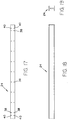
- Each of the frame beams 24 comprises upper and lower flanges 32 and 34 respectively connected by a central vertical web 36.
- a quantity of spaced apertures, illustrated at 38 which may, for example, have a diameter of about 11/16 inch, are provided along and adjacent each edge of the upper and lower flanges 32 and 34 respectively.
- the apertures 38 are preferably spaced closely together, preferably in equal increments.
- the apertures 38 may be spaced about 12 inches (on centers) apart, as illustrated at 39, with end apertures, illustrated at 40, (on centers) being spaced, for example, about 3 1 ⁇ 2 inches from the frame beam edge and about 2 3/8 inches from the adjacent set of apertures 38.
- end apertures, illustrated at 40 on centers
- Each group of frame beams 24 comprises a plurality of frame beams 24 connected end-to-end co-axially to extend the width of the bridge 22 or otherwise desired distance, with additional groups of frame beams 24 laid parallel thereto along the bridge length or otherwise desired distance (with the deck support beams 26 inserted between and attached at their ends to respective frame beams 24 to extend normal or perpendicular thereto).
- a pair of end-to-end co-axial frame beams 24 are connected by a pair of connectors 52, which may, for example, be blocks composed of extruded aluminum or other suitable material and having a pair of spaced apertures 54, whose spacing is such as to allow them to be aligned with the apertures 40 adjacent the ends of the respective frame beams 24, leaving the gap 41.
- the pair of connectors 52 span the ends of the flanges 32 and 34 respectively on the respective flange sides.
- each frame beam 24 is by means of a pin 56 which is received in the respective upper and lower flange apertures 40 and in the respective connector aperture 54, which may, for example, have a diameter of about 5/8 inch, as discussed in greater detail hereinafter.
- the pin 56 may be composed, for example, of suitably hardened steel or stainless steel and have an upper cap portion 58 to rest on top of the upper flange 32 and a lower tapered or pointed end 60 for ease of insertion.
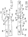
- the frame beam 24 to be installed may be held in a substantially side-by-side relation relative to the previously installed frame beam 24, as illustrated in FIG. 27 , and one of the connectors 52 attached by insertion of the pins 56 respectively.
- the frame beam 24 to be installed is then swung (about the off-center attachment of the pins 56) around, as illustrated at 57 in FIG. 27 , to position it in the desired end-to-end co-axial relation with the previously installed frame beam 24, as illustrated in FIG. 28 , and the second connector 52 attached by insertion of the pins 56 respectively.
- the beams 24 and 26 may be provided in different lengths to allow flexibility in construction, but the beams 24 are otherwise desirably identical and the beams 26 are otherwise desirably identical and the connectors 48 are desirably identical to allow minimization of the types of parts needed for erecting the modular platform. Likewise, the first and second connectors 52 and the pins 56 are desirably identical.
- a deck support beam 26 is attached to a frame beam 24 by means of block 48.
- the block 48 may advantageously be formed by machining an extruded block 52 to form therefrom a portion 62 containing one of the apertures 54 and two spaced flanges 64 (only one seen in FIG. 5 ) extending laterally therefrom.
- Each of the flanges 64 is sized height-wise to fit between the deck support beam flanges 42 and 44 and is shown to have three aligned triangularly-spaced apertures, illustrated at 66, which also align with apertures (not shown) in the respective end of the deck support beam web 46 wherein the web 46 is sandwiched between the flanges 64, and bolts 68 are inserted in the apertures 66 and the deck support beam web apertures respectively and nuts (not shown) suitably applied to rigidly secure the machined block 62 to the respective end of the deck support beam 26.
- the block portion 62 is received between the flanges 32 and 34 with its aperture 54 aligned with the apertures 38 and a pin 56 inserted within the respective flange apertures 38 and the block aperture 54, similarly as the pins 56 attach the extruded blocks 52 to the ends of two frame beams 24 to connect them together, as discussed in greater detail herein.
- the deck support beam 26 may desirably be held next to or alongside the frame beam 24, i.e., in a substantially side-by-side relation, as illustrated in FIG. 28 , then swung into position, as illustrated at 59 in FIG. 28 , after the pin 56 has been inserted, to the position shown in FIG.
- deck support beam 26 is normal or perpendicular to the respective frame beam 24.
- the ends of the flanges 42 and 44 are suitably chamfered, as illustrated at 67, for example, over a distance of about 6 inches, to narrow ends 70 to prevent interference with the corresponding frame beam 24.
- the close spacing of the frame beam apertures 38 allows flexibility for positioning of the deck support beams 26 generally anywhere there along, including flexibility for erecting around obstacles and in tight areas.
- the attachment of a second frame beam 24 to the other ends of deck support beams 26 previously attached to a first frame beam 24 may be with the deck support beams 26 rotated or swung into a position adjacent (substantially side-by-side with) the first frame beam 24, then the assembly rotated out into position for attachment of the second frame beam 24 in end-to-end co-axial relation with a previously attached frame beam 24.
- the frame beams 24 and the deck support beams 26 may desirably be attached in either order, allowing flexibility for erection.
- each flooring panel 30 is suitably attached to extruded aluminum (or other suitable material) elongate members 72 which are in turn attached to respective deck support beams 26, as described hereinafter.
- each of the members 72 has an upper slot, illustrated at 76, extending into one side thereof and defined by a thin upper lip 78 and in which is frictionally or snugly received the respective edge portion of the respective flooring panel 30.
- a notch, illustrated at 74, is formed in the other side lower corner of the member 72 in which is receivable the respective one side of the upper flange 42.
- FIGS. 8 and 9 illustrate the member 72 as applied to one panel edge and the means for its attachment to the respective deck support beam 26 and
- FIGS. 10 and 11 illustrate the member 72 as applied to the opposite panel edge and the means for its attachment to the respective deck support beam 26.
- a pair of spaced plates 75 are suitably attached such as by screws or bolts or welding (not shown) to the lower surface of the member 72, the plates 75 extending inwardly to overlap the notch 74 and form therewith a slot, illustrated at 77, in which the respective facing side or half of the upper flange 42 is received for the purpose of securing the one side of the panel 30.
- a suitably spring-loaded locking mechanism 86 having a protrudable bolt or tongue 88 is suitably attached such as by screws or bolts (not shown) to the lower surface of the member 72, centrally thereof, the bolt 88 when protruding extending inwardly to overlap the notch 74 and form therewith a slot, illustrated at 77, in which the respective facing side or half of the upper flange 42 is received for the purpose of securing the other side of the panel 30.
- the locking mechanism 86 and bolt 88 are similar to mechanisms and bolts found on many doors to cause a door to automatically lock when pulled closed.
- the bolt 88 is adapted to be pushed into the locking mechanism 86, which is spring-loaded to bias the bolt 88 to the outward position shown in FIG. 11 .
- the bolt 88 lower surface is suitably shaped to cause the bolt 88 to be pushed inwardly of the locking mechanism 86 when force is applied to it from above against the upper flange 42.
- the spring-loaded mechanism 86 forces the bolt 88 outwardly into the position shown in FIG. 11 once the upper flange 42 is cleared.
- the principles of construction of such a locking mechanism 86 and bolt 88 are well known to those of ordinary skill in the art to which the present invention pertains.
- the connectors 72 are applied to the opposite panel edges and may be suitably glued thereto, the two connectors 72 for one edge having the members 75 attached and the connector 72 for the other edge having the locking mechanism 86 and bolt 88 attached.
- the panel 30 is positioned so that the flange 42 is received in the slot 77 formed by the member 75.
- downward force is applied, causing the bolt 88 to retract into the locking mechanism 86 so that the flange 42 can be received in the slot 77 formed by the bolt 88.
- the spring force of the locking mechanism 86 forces the bolt 88 back outwardly to again form the slot 77 with the flange 42 securely received therein.
- the panels 30 make the platform portion rigid.
- the lower surface of the slot 76 is even with or slightly higher than the surface formed by the notch 74 which rests on top of the deck support beam flange 42 which allows the panels 30 to be positioned height-wise to clear other deck support beams 26, as desired.
- a deck support beams 26 may be positioned centrally under the three panels 30 for added support thereof as well as making erection easier.
- the lip 78 can be formed to be very thin, such as, for example, 1/8 inch, so that a substantially even or almost flush walking surface may desirably be achieved.
- an extruded block 90 of aluminum or other suitable material is provided to attach each shackle 29 (for example, a 3/4 inch shackle) to a frame beam 24.
- the block 90 is formed to have two apertures, illustrated at 92, extending vertically therethrough and spaced to be alignable with a pair of inner and outer apertures 38 on the frame beams 24.
- the block 90 is attached by suitable means such as, for example, a pair of bolts 94 (for example, 5/8 inch bolts) received in the apertures 92 and 38 respectively and nuts 96 applied to the bolts 94 to rigidly secure the block 90.
- a slot, illustrated at 98 is suitably formed in the lower surface of the block 90. When attached to the respective frame beam 24, it forms therewith an opening in which is receivable a fastener member 100 for attaching the shackle 29 to the frame beam 24.
- an elastomeric seal member or self-sealing rubber seal 102 has a central portion 104 which is received within the gap 41 between adjacent flanges 32 of frame beams 24 respectively and terminates in an enlarged lower portion 106 which is receivable below and engages the lower surfaces of the flanges 32 so that it is securely held within the gap 41.
- the seal 102 extends over the entire length of the gap 41.
- the upper end of the central portion 104 terminates in a cap portion 108 which is sized to cover the caps 58 of the pins 56 to protect and secure them against dislodgement.
- the elastomeric material is such as to allow the portion 106 to be compressible to be passed through the gap 41 then expand to secure the seal 102 against dislodgement. During disassembly, the portion 106 can then be compressed again by application of suitable pulling force for passage through the gap 41 and removal of the seal 102. Similar seals may be provided in other gaps in the platform such as, for example, in gaps between panels 30.
- the apertures 40 are not needed for attachment of another frame beam.
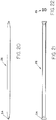
- FIG. 16 there is shown schematically the attachment of an elongate vertical railing post 110 at one of these ends for a hand rail for perimeter protection, the hooks 112 being for the running of cables or lines between posts 110.
- the post 110 may be attached in any suitable way, for example, by supporting locking mechanisms which contain bolts or tongues or pins, illustrated at 111, which are suitably caused to lockingly pop into the apertures 40 in a manner commonly known to those of ordinary skill in the art to which the present invention pertains.
- each of the washers 114 has a tubular portion 116 and a flat portion 118 extending laterally and radially outwardly from one end thereof.
- the flat portions 118 of two washers 114 are received between the upper end surface of the connector 52 and the lower surface of the lower flange 32, the tubular portion of the upper of the two upper washers 114 extends upwardly and is received between the pin 56 and the wall of the aperture 40, and the tubular portion of the lower of the two upper washers 114 extends downwardly and is received between the pin 56 and the wall of the aperture 54.
- the two lower washers 114 are similarly positioned, as shown in FIG. 26 .
- the provision of the washers 114 leaves a gap, illustrated at 120, over most of the height of the aperture 54 between the ends, illustrated at 122, of the lower of the upper washers 114 and the upper of the lower washers 114.
- the washers 114 are sized so that the tubular portion 116 of the upper one of the washers 114 has a terminal upper end portion 126 which extends slightly above the upper flange 32, for example, about 1/16 inch, so as to prevent rubbing contact with the flange 32 by the pin cap 58. These washers 114 may be glued in place. These washers are not depicted in FIG. 14 . Similar washers of Teflon polymer are used similarly in connecting the deck support beams 26 to the frame beams 24.
- the washers 114 may be made of other suitable polymer or other materials which provide reduced friction contact for easier movements while preventing undesirable metal-to-metal contact.
- each of the components is sized and made of a material so that it weighs less than about 50 pounds.
- the heaviest of the components in the platform 20 as described herein, which is a plywood panel 30, is sized to weigh less than 50 pounds, and the remaining components are sized and made of a material to also weigh less than 50 pounds.
- aluminum is the material of which most of the components is made, aluminum having a density of about 0.1 pounds per cubic inch, as compared to steel having a density of about 0.28 pounds per cubic inch.
- substantially lesser density of aluminum desirably allows the achievement of the component weight of less than 50 pounds for all components of the platform 20.
- the light-weight components of the modular platform 20 may be connected together easily and safely and quickly without the need for cranes or other heavy equipment and while allowing flexibility for erecting around obstacles and in tight areas.
- Most of the major parts are advantageously extruded from aluminum or other suitable light-weight material, and the deck support beam connector blocks 48 advantageously machined from the frame beam connector blocks 52, thus desirably providing ease of manufacture with little or no welding, thereby further allowing more uniform preciseness for ease of assembly.
Landscapes
- Engineering & Computer Science (AREA)
- Architecture (AREA)
- Mechanical Engineering (AREA)
- Civil Engineering (AREA)
- Structural Engineering (AREA)
- Bridges Or Land Bridges (AREA)
Claims (15)
- Plattform (20), bestehend aus einer Kombination von Teilen, einschließlich Rahmenträger (24), Blöcke (52) und Stifte (56), die dazu montiert und demontiert werden können, um die Plattform (20) auf- und abzubauen, wobei die Rahmenträger (24) jeweils einen oberen Gurt (32) und einen unteren Gurt (34) aufweisen und die Rahmenträger (24) Ende an Ende angeordnet sind, wodurch ein Endabschnitt eines der Rahmenträger (24) neben einem Endabschnitt eines anderen der Rahmenträger (24) liegt, wobei ein Paar der Blöcke (52) jeweils zwischen dem oberen (32) und unteren (34) Gurt sowohl des Endabschnitts des einen Rahmenträgers (24) als auch des Endabschnitts des anderen Rahmenträgers (24) entfernbar aufgenommen wird, um die Rahmenträger (24) Ende an Ende zu verbinden, wobei jeder der Blöcke (52) ein Paar Bohrlöcher (54) aufweist, wobei jeder der Endabschnitte der Rahmenträger ein Paar Öffnungen (40) im oberen Gurt (32) und ein Paar Öffnungen (40) im unteren Gurt (34) aufweist, wobei ein erster der Stifte (56) in einem des Paars Bohrlöcher (54) in jedem der Blöcke (52) sowie in den entsprechenden Öffnungen (40) im oberen und unteren Gurt (32, 34) des einen Rahmenträgers (24) entfernbar aufgenommen wird, wobei ein zweiter der Stifte (56) in einem anderen des Paars Bohrlöcher (54) in jedem der Blöcke (52) sowie in den entsprechenden Öffnungen (40) im oberen und unteren Gurt (32, 34) des anderen Rahmenträgers (24) entfernbar aufgenommen wird, wodurch das Paar Blöcke (52) mit dem einen und dem anderen Rahmenträger (24) verbunden wird, wodurch, wenn nur einer der Blöcke (52) den einen und den anderen Rahmenträger (24) verbindet, der andere Rahmenträger (24) relativ zu dem einen Rahmenträger (24) schwingbar ist, und zwar aus einer Position, in welcher sich der eine und der andere Rahmenträger (24) im Wesentlichen Seite an Seite zu der Ende-an-Ende-Position verhalten, und wodurch der eine und der andere Rahmenträger (24) in der Ende-an-Ende-Position gehalten werden können, wenn der eine und der andere Rahmenträger (24) mit beiden des Paars Blöcke (52) verbunden sind.
- Plattform (20) nach Anspruch 1, wobei die Kombination von Teilen ferner eine Vielzahl von Deckstützbalken (26) umfasst, eine Vielzahl von Deckstützbalken-Verbindungselementen (48) zum Verbinden der Deckstützbalken (26) mit den Rahmenträgern (24), damit sie senkrecht zu diesen verlaufen, wobei jeder Rahmenträger (24) eine Vielzahl von Öffnungen (38) aufweist, die zur Aufnahme von Stiften (56) gleichmäßig über eine Länge desselben beabstandet sind, um die Deckstützbalken-Verbindungselemente (48) daran zu befestigen, was die Befestigung der Deckstützbalken-Verbindungselemente (48) an verschiedenen Stellen über die Länge des jeweiligen Rahmenträgers (24) ermöglicht.
- Plattform (20) nach Anspruch 1, wobei die Kombination von Teilen ferner eine Vielzahl von Deckstützbalken (26) zur Querverbindung der Rahmenträger (24), eine Vielzahl von Platten (30), eine erste Vielzahl von Plattenverbindern (72) zum Verbinden von Rändern der Platten (30) mit den Deckstützbalken (26) und eine zweite Vielzahl von Plattenverbindern (72) zum Verbinden von Rändern der Platten (30) mit den Deckstützbalken (26) umfasst, wobei die ersten und zweiten Plattenverbinder (72) einen ersten Schlitz (76) aufweisen, um einen Randabschnitt einer der Platten (30) aufzunehmen, wobei jeder der ersten Plattenverbinder (72) einen zweiten Schlitz (77) aufweist, um einen Gurt (42, 44) eines der Deckstützbalken (26) aufzunehmen, und wobei jeder der zweiten Plattenverbinder (72) einen dritten Schlitz (77) aufweist, um einen Gurt (42, 44) eines der Deckstützbalken (26) aufzunehmen, wobei der zweite Plattenverbinder (72) einen federbelasteten Bolzen (88) umfasst, der teilweise den dritten Schlitz (77) definiert, und der bewegbar ist, um es einem Randabschnitt der jeweiligen Platte (30) zu ermöglichen, in dem dritten Schlitz aufgenommen zu werden, und der vorgespannt ist, um den jeweiligen Plattenrandabschnitt im dritten Schlitz zu halten.
- Kombination von Teilen aus Anspruch 1 zum Errichten einer Plattform (20), Folgendes umfassend: eine Vielzahl von Rahmenträgern (24), eine Vielzahl von Blöcken (52) zum Verbinden der Rahmenträger (24), sodass diese Ende an Ende angeordnet sind, wobei die Rahmenträger (24) und die Blöcke (52) so ausgestaltet sind, dass sie ein Paar der Blöcke (52) mit jedem Ende der Rahmenträger (24) derart verbinden, dass einer des Paars der Blöcke (52) mit einem Paar der Rahmenträger (24) verbindbar ist, wenn sich das Paar der Rahmenträger (24) im Wesentlichen Seite an Seite befindet, und, während der eine des Paars der Blöcke (52) mit dem Paar der Rahmenträger (24) verbunden ist, wobei einer des Paars der Rahmenträger (24) relativ zu einem anderen des Paars der Rahmenträger (24) in ein koaxiales Verhältnis dazu schwingbar ist, und zwar derart, dass ein anderer des Paars der Blöcke (52) mit dem Paar der Rahmenträger (24) verbindbar ist, wenn sich das Paar der Rahmenträger (24) in dem koaxialen Verhältnis befindet, um das Paar der Rahmenträger (24) in dem koaxialen Verhältnis zu halten, wobei die Rahmenträger (24) I-Träger mit einem Paar Gurte (32, 34) sind, die durch einen Steg (36) verbunden sind, wobei die Blöcke (52) so bemessen sind, dass sie zwischen den Gurten (32, 34) aufgenommen werden können, wobei jeder der Blöcke (52) ein Paar Bohrlöcher (54) aufweist, die sich dadurch erstrecken, wobei die Gurte (32, 34) Öffnungen (40) darin auf beiden Seiten des Stegs (36) sowie neben jedem Ende des jeweiligen Rahmenträgers (24) aufweisen, wobei die Bohrlöcher (54) so beabstandet sind, dass sie sich jeweils auf die Gurtöffnungen (40) auf einer Seite des Stegs (36) in einem Endabschnitt eines der Rahmenträgers (24) sowie auf die Gurtöffnungen (40) auf einer Seite des Stegs (36) in einem Endabschnitt eines anderen Rahmenträgers (24) ausrichten lassen, wenn der andere Rahmenträger (24) allgemein Ende an Ende mit dem einen Rahmenträger (24) angeordnet ist, und wobei die Kombination ferner Stifte (56) umfasst, die in den Borlöchern (54) und den jeweiligen Öffnungen (40) entfernbar aufgenommen werden können, um die Rahmenblöcke (52) mit den Rahmenträgern (24) zu verbinden.
- Kombination nach Anspruch 4, wobei die Öffnungen (40) von den jeweiligen Enden der jeweiligen Rahmenträger (24) in einem Abstand beabstandet sind, der einen Zwischenraum(41) zwischen den jeweiligen Rahmenträgern (24) ermöglicht, wenn diese in dem koaxialen Verhältnis verbunden sind, wobei die Kombination ferner eine Vielzahl von Elastomerelementen (102) umfasst, die sich in die Zwischenräume (41) einfügen lassen, um jeweils die Zwischenräume (41) zu füllen, und Kappenabschnitte (108) aufweisen, die so bemessen sind, dass sie jeweils die Stifte (56) abdecken.
- Kombination nach Anspruch 4, wobei jedes der Teile weniger als circa 50 Pfund bzw. 22,68 kg wiegt.
- Kombination nach Anspruch 4, ferner eine Vielzahl von Deckstützbalken (26) umfassend, die sich jeweils zwischen einem Paar paralleler Rahmenträger (24) erstrecken und diese verbinden, und eine Vielzahl von Deckstützbalken-Verbindungselemente (48) zum Verbinden der Deckstützbalken (26) mit den Rahmenträgern (24), auf eine Art und Weise, dass einer der Deckstützbalken (26) mit einem der Rahmenträger (24) verbunden werden kann, während einer der Deckstützbalken (26) im Wesentlichen Seite an Seite mit einem der Rahmenträger (24) angeordnet ist, und um es dem einen der Deckstützbalken (26) zu ermöglichen, in eine Position gedreht zu werden, die senkrecht zu einem der Rahmenträger (24) ist, während er mit dem einen der Rahmenträger (24) verbunden ist.
- Kombination nach Anspruch 7, wobei die Stifte (56) so bemessen sind, dass sie jeweils auch die Deckstützbalken-Verbindungselemente (48) mit den Deckstützbalken (26) verbinden.
- Kombination nach Anspruch 4, ferner eine Vielzahl von identischen nichtmetallischen Lagerelementen (114) umfassend, die jeweils einen zylinderförmigen Abschnitt (116), um den jeweiligen Stift (56) aufzunehmen, sowie einen flachen Abschnitt (118) aufweisen, um eine jeweilige Oberfläche eines beliebigen der Rahmenträger-Verbindungselemente (52), der Rahmenträger (24), der Deckstützbalken-Verbindungselemente (48) und der Deckstützbalken (26) zu greifen, um einen Metall-an-Metall-Kontakt durch die Stifte (56) zu vermeiden.
- Kombination nach Anspruch 7, wobei jeder der Gurte (32, 34) des jeweiligen Rahmenträgers (24) eine Vielzahl von Öffnungen (38) aufweist, die jeweils entlang dessen Länge beabstandet sind, und wobei jedes Deckstützbalken-Verbindungselement (48) einen ersten Abschnitt umfasst, der dazu bemessen ist, zwischen den Gurten (32, 34) aufgenommen zu werden, und ein Bohrloch (50) aufweist, das sich dadurch erstreckt, wobei die Kombination ferner eine Vielzahl von Stiften (56) umfasst, die in der Vielzahl von Öffnungen (38) und dem Bohrloch (50) jeweils aufgenommen werden können, um jeweils eine drehbare Bewegung der Deckstützbalken-Verbindungselemente (48) um die Stifte (56) zu ermöglichen.
- Kombination nach Anspruch 7, wobei jeder der Rahmenträger (24) und jeder der Deckstützbalken (26) aus Aluminium besteht.
- Verfahren zum Errichten einer Plattform nach Anspruch 1, die folgenden Schritte umfassend:(a) Einfügen eines ersten einer Vielzahl von Blöcken (52) zwischen dem oberen und unteren Gurt (32, 34) in einem Endabschnitt jedes der beiden eines Paars Rahmenträger (24), Einfügen eines ersten Stifts (56) in ein erstes Bohrloch (54) im ersten Block (52) und in Öffnungen (40) im oberen und unteren Gurt (32, 34) eines ersten des Paars Rahmenträger (24), und Einfügen eines zweiten Stifts (56) in ein zweites Bohrloch (54) im ersten Block (52) und in Öffnungen (40) im oberen und unteren Gurt (32, 34) eines zweiten des Paars Rahmenträger (24), wodurch das Paar Rahmenträger (24) verbunden wird, während das Paar Rahmenträger (24) im Wesentlichen Seite an Seite angeordnet ist;(b) Schwingen des zweiten des Paars Rahmenträger (24) relativ zum ersten des Paars Rahmenträger (24) in eine koaxiale Position des Paars Rahmenträgers (24) relativ zueinander; und(c) Einfügen eines zweiten der Blöcke (52) zwischen den oberen und unteren Gurt (32, 34) im Endabschnitt jedes der beiden des Paars Rahmenträger (24), während sich das Paar Rahmenträger (24) in der koaxialen Position befindet, Einfügen eines dritten Stifts (56) in ein Bohrloch im zweiten Block (52) und in andere Öffnungen (40) im oberen und unteren Gurt (32, 34) des ersten des Paars Rahmenträger (24), und Einfügen eines vierten Stifts (56) in ein anderes Bohrloch (54) im zweiten Block (52) und in andere Öffnungen (40) im oberen und unteren Gurt (32, 34) des zweiten des Paars Rahmenträger (24), wodurch das Paar Rahmenträger (24) in der koaxialen Position gehalten wird.
- Verfahren nach Anspruch 12, ferner umfassend das Verbinden eines Deckstützbalkens (26) mit einem der Rahmenträger (24), während der Deckstützbalken (26) im Wesentlichen Seite an Seite dazu angeordnet ist; Schwingen des Deckstützbalkens (26) in eine Position, die senkrecht zu dem einen der Rahmenträger (24) verläuft; und Verbinden des Deckstützbalkens (26) mit einem anderen der Rahmenträger (24).
- Verfahren nach Anspruch 12, ferner umfassend das Einfügen eines Abschnitts eines Blocks (52), an dem ein Deckstützbalken (26) befestigt ist, und zwar zwischen dem oberen und unteren Gurt (32, 34) eines der Endabschnitte der Rahmenträger (24), während sich der Deckstützbalken (26) im Wesentlichen Seite an Seite damit befindet; Einfügen eines fünften Stifts (56) in ein erstes Bohrloch (54) im Deckstützbalkenblock (52) und in entsprechende Öffnungen (40) im oberen und unteren Gurt (32, 34) des einen Rahmenträgers (24); Schwingen des Deckstützbalkens (26) in eine Position, die senkrecht zu dem einen Rahmenträger verläuft (24); und Verbinden des Deckstützbalkens (26) mit einem anderen der Rahmenträger (24).
- Verfahren nach Anspruch 12, ferner das Auswählen von Rahmenträgern (24), Blöcken und Stiften (56) umfassend, sodass jedes der Teile weniger als circa 50 Pfund bzw. 22,68 kg wiegt.
Applications Claiming Priority (1)
| Application Number | Priority Date | Filing Date | Title |
|---|---|---|---|
| PCT/US2012/025702 WO2013122607A1 (en) | 2012-02-17 | 2012-02-17 | Modular platform/scaffolding |
Publications (3)
| Publication Number | Publication Date |
|---|---|
| EP2815041A1 EP2815041A1 (de) | 2014-12-24 |
| EP2815041A4 EP2815041A4 (de) | 2015-10-21 |
| EP2815041B1 true EP2815041B1 (de) | 2017-09-13 |
Family
ID=48984575
Family Applications (1)
| Application Number | Title | Priority Date | Filing Date |
|---|---|---|---|
| EP12868576.5A Active EP2815041B1 (de) | 2012-02-17 | 2012-02-17 | Modulare plattform/modulares gerüst |
Country Status (2)
| Country | Link |
|---|---|
| EP (1) | EP2815041B1 (de) |
| WO (1) | WO2013122607A1 (de) |
Families Citing this family (5)
| Publication number | Priority date | Publication date | Assignee | Title |
|---|---|---|---|---|
| US9388589B2 (en) | 2013-05-21 | 2016-07-12 | Safway Services, Llc | Work platform system including suspended paneled portion and method of implementing same |
| US9410333B2 (en) | 2013-05-21 | 2016-08-09 | Safway Services, Llc | Work platform system including suspended paneled portion and method of implementing same |
| US9976264B2 (en) | 2013-05-21 | 2018-05-22 | Safway Services, Llc | Work platform system including suspended paneled portion and method of implementing same |
| US20160312481A1 (en) | 2015-04-27 | 2016-10-27 | Rolling Easy Platforms, LLC | Work platform rail system |
| JP6783011B1 (ja) * | 2020-03-05 | 2020-11-11 | ▲蔦▼井株式会社 | 吊り足場 |
Family Cites Families (4)
| Publication number | Priority date | Publication date | Assignee | Title |
|---|---|---|---|---|
| US2744590A (en) * | 1950-12-12 | 1956-05-08 | Alfred M Butts | Load-supporting structures |
| SU1470837A1 (ru) * | 1987-08-20 | 1989-04-07 | Харьковский инженерно-строительный институт | Стыковое прессовое соединение |
| JPH1113276A (ja) * | 1997-06-20 | 1999-01-19 | Anzen Kigu Kk | 足場構造体 |
| US7779599B2 (en) * | 2004-03-31 | 2010-08-24 | Safway Services, Llc | Articulating work platform support system, work platform system, and methods of use thereof |
-
2012
- 2012-02-17 WO PCT/US2012/025702 patent/WO2013122607A1/en not_active Ceased
- 2012-02-17 EP EP12868576.5A patent/EP2815041B1/de active Active
Also Published As
| Publication number | Publication date |
|---|---|
| EP2815041A4 (de) | 2015-10-21 |
| EP2815041A1 (de) | 2014-12-24 |
| WO2013122607A1 (en) | 2013-08-22 |
Similar Documents
| Publication | Publication Date | Title |
|---|---|---|
| US8123001B1 (en) | Modular platform/ scaffolding | |
| US5730245A (en) | Safety cable deck anchor | |
| US12173501B2 (en) | Modular space frame support system, work platform system and methods of erecting the same | |
| US10329781B2 (en) | Safety barrier netting system | |
| EP3147425B1 (de) | Nabe | |
| US10435895B2 (en) | Adjustable platform extension bracket for work platform systems and related methods | |
| US6264002B1 (en) | Scaffolding for bridges and other structures | |
| US5263296A (en) | Modular scaffolding assembly | |
| US2233901A (en) | System of adaptable elements for temporary or permanent structural framing | |
| US4965903A (en) | Modular bridge | |
| US4602470A (en) | Dismountable framework | |
| US4276959A (en) | Quick way scaffold | |
| WO2013122607A1 (en) | Modular platform/scaffolding | |
| JP2016511345A (ja) | 協働して仮設ステアケースを形成するステアモジュール | |
| JPH0819759B2 (ja) | モジュール型足場装置とその接続ジョイント | |
| US5911288A (en) | Bridge painting platform | |
| EP4007835B1 (de) | Monoschienenbaugruppe und monoschienensystem | |
| EP0117643B1 (de) | Zerlegbares Rahmenwerk | |
| US4098045A (en) | Wall forming construction unit | |
| US20060135005A1 (en) | Snappy structural system | |
| CA3010470A1 (en) | Modular scaffolding system | |
| US20230265645A1 (en) | Modular space frame support system, work platform system and methods of erecting the same | |
| AU2012101509B4 (en) | Improvements in Brackets |
Legal Events
| Date | Code | Title | Description |
|---|---|---|---|
| PUAI | Public reference made under article 153(3) epc to a published international application that has entered the european phase |
Free format text: ORIGINAL CODE: 0009012 |
|
| 17P | Request for examination filed |
Effective date: 20140915 |
|
| AK | Designated contracting states |
Kind code of ref document: A1 Designated state(s): AL AT BE BG CH CY CZ DE DK EE ES FI FR GB GR HR HU IE IS IT LI LT LU LV MC MK MT NL NO PL PT RO RS SE SI SK SM TR |
|
| AX | Request for extension of the european patent |
Extension state: BA ME |
|
| DAX | Request for extension of the european patent (deleted) | ||
| RA4 | Supplementary search report drawn up and despatched (corrected) |
Effective date: 20150918 |
|
| RIC1 | Information provided on ipc code assigned before grant |
Ipc: E04B 5/14 20060101ALI20150914BHEP Ipc: E04C 3/00 20060101ALI20150914BHEP Ipc: E04G 3/30 20060101ALI20150914BHEP Ipc: E04B 1/24 20060101ALN20150914BHEP Ipc: E01D 22/00 20060101ALN20150914BHEP Ipc: E04G 3/00 20060101AFI20150914BHEP |
|
| GRAP | Despatch of communication of intention to grant a patent |
Free format text: ORIGINAL CODE: EPIDOSNIGR1 |
|
| RIC1 | Information provided on ipc code assigned before grant |
Ipc: E04B 1/24 20060101ALN20170112BHEP Ipc: E04C 3/00 20060101ALI20170112BHEP Ipc: E01D 22/00 20060101ALN20170112BHEP Ipc: E04G 3/00 20060101AFI20170112BHEP Ipc: E04G 3/30 20060101ALI20170112BHEP Ipc: E04B 5/14 20060101ALI20170112BHEP |
|
| INTG | Intention to grant announced |
Effective date: 20170201 |
|
| GRAS | Grant fee paid |
Free format text: ORIGINAL CODE: EPIDOSNIGR3 |
|
| GRAA | (expected) grant |
Free format text: ORIGINAL CODE: 0009210 |
|
| AK | Designated contracting states |
Kind code of ref document: B1 Designated state(s): AL AT BE BG CH CY CZ DE DK EE ES FI FR GB GR HR HU IE IS IT LI LT LU LV MC MK MT NL NO PL PT RO RS SE SI SK SM TR |
|
| REG | Reference to a national code |
Ref country code: GB Ref legal event code: FG4D |
|
| REG | Reference to a national code |
Ref country code: CH Ref legal event code: EP |
|
| REG | Reference to a national code |
Ref country code: IE Ref legal event code: FG4D |
|
| REG | Reference to a national code |
Ref country code: AT Ref legal event code: REF Ref document number: 928297 Country of ref document: AT Kind code of ref document: T Effective date: 20171015 |
|
| REG | Reference to a national code |
Ref country code: DE Ref legal event code: R096 Ref document number: 602012037449 Country of ref document: DE |
|
| REG | Reference to a national code |
Ref country code: NL Ref legal event code: MP Effective date: 20170913 |
|
| REG | Reference to a national code |
Ref country code: LT Ref legal event code: MG4D |
|
| PG25 | Lapsed in a contracting state [announced via postgrant information from national office to epo] |
Ref country code: FI Free format text: LAPSE BECAUSE OF FAILURE TO SUBMIT A TRANSLATION OF THE DESCRIPTION OR TO PAY THE FEE WITHIN THE PRESCRIBED TIME-LIMIT Effective date: 20170913 Ref country code: SE Free format text: LAPSE BECAUSE OF FAILURE TO SUBMIT A TRANSLATION OF THE DESCRIPTION OR TO PAY THE FEE WITHIN THE PRESCRIBED TIME-LIMIT Effective date: 20170913 Ref country code: NO Free format text: LAPSE BECAUSE OF FAILURE TO SUBMIT A TRANSLATION OF THE DESCRIPTION OR TO PAY THE FEE WITHIN THE PRESCRIBED TIME-LIMIT Effective date: 20171213 Ref country code: LT Free format text: LAPSE BECAUSE OF FAILURE TO SUBMIT A TRANSLATION OF THE DESCRIPTION OR TO PAY THE FEE WITHIN THE PRESCRIBED TIME-LIMIT Effective date: 20170913 Ref country code: HR Free format text: LAPSE BECAUSE OF FAILURE TO SUBMIT A TRANSLATION OF THE DESCRIPTION OR TO PAY THE FEE WITHIN THE PRESCRIBED TIME-LIMIT Effective date: 20170913 |
|
| REG | Reference to a national code |
Ref country code: AT Ref legal event code: MK05 Ref document number: 928297 Country of ref document: AT Kind code of ref document: T Effective date: 20170913 |
|
| PG25 | Lapsed in a contracting state [announced via postgrant information from national office to epo] |
Ref country code: RS Free format text: LAPSE BECAUSE OF FAILURE TO SUBMIT A TRANSLATION OF THE DESCRIPTION OR TO PAY THE FEE WITHIN THE PRESCRIBED TIME-LIMIT Effective date: 20170913 Ref country code: BG Free format text: LAPSE BECAUSE OF FAILURE TO SUBMIT A TRANSLATION OF THE DESCRIPTION OR TO PAY THE FEE WITHIN THE PRESCRIBED TIME-LIMIT Effective date: 20171213 Ref country code: GR Free format text: LAPSE BECAUSE OF FAILURE TO SUBMIT A TRANSLATION OF THE DESCRIPTION OR TO PAY THE FEE WITHIN THE PRESCRIBED TIME-LIMIT Effective date: 20171214 Ref country code: LV Free format text: LAPSE BECAUSE OF FAILURE TO SUBMIT A TRANSLATION OF THE DESCRIPTION OR TO PAY THE FEE WITHIN THE PRESCRIBED TIME-LIMIT Effective date: 20170913 Ref country code: ES Free format text: LAPSE BECAUSE OF FAILURE TO SUBMIT A TRANSLATION OF THE DESCRIPTION OR TO PAY THE FEE WITHIN THE PRESCRIBED TIME-LIMIT Effective date: 20170913 |
|
| PG25 | Lapsed in a contracting state [announced via postgrant information from national office to epo] |
Ref country code: NL Free format text: LAPSE BECAUSE OF FAILURE TO SUBMIT A TRANSLATION OF THE DESCRIPTION OR TO PAY THE FEE WITHIN THE PRESCRIBED TIME-LIMIT Effective date: 20170913 |
|
| PG25 | Lapsed in a contracting state [announced via postgrant information from national office to epo] |
Ref country code: CZ Free format text: LAPSE BECAUSE OF FAILURE TO SUBMIT A TRANSLATION OF THE DESCRIPTION OR TO PAY THE FEE WITHIN THE PRESCRIBED TIME-LIMIT Effective date: 20170913 Ref country code: RO Free format text: LAPSE BECAUSE OF FAILURE TO SUBMIT A TRANSLATION OF THE DESCRIPTION OR TO PAY THE FEE WITHIN THE PRESCRIBED TIME-LIMIT Effective date: 20170913 Ref country code: PL Free format text: LAPSE BECAUSE OF FAILURE TO SUBMIT A TRANSLATION OF THE DESCRIPTION OR TO PAY THE FEE WITHIN THE PRESCRIBED TIME-LIMIT Effective date: 20170913 |
|
| PG25 | Lapsed in a contracting state [announced via postgrant information from national office to epo] |
Ref country code: EE Free format text: LAPSE BECAUSE OF FAILURE TO SUBMIT A TRANSLATION OF THE DESCRIPTION OR TO PAY THE FEE WITHIN THE PRESCRIBED TIME-LIMIT Effective date: 20170913 Ref country code: IT Free format text: LAPSE BECAUSE OF FAILURE TO SUBMIT A TRANSLATION OF THE DESCRIPTION OR TO PAY THE FEE WITHIN THE PRESCRIBED TIME-LIMIT Effective date: 20170913 Ref country code: SM Free format text: LAPSE BECAUSE OF FAILURE TO SUBMIT A TRANSLATION OF THE DESCRIPTION OR TO PAY THE FEE WITHIN THE PRESCRIBED TIME-LIMIT Effective date: 20170913 Ref country code: AT Free format text: LAPSE BECAUSE OF FAILURE TO SUBMIT A TRANSLATION OF THE DESCRIPTION OR TO PAY THE FEE WITHIN THE PRESCRIBED TIME-LIMIT Effective date: 20170913 Ref country code: IS Free format text: LAPSE BECAUSE OF FAILURE TO SUBMIT A TRANSLATION OF THE DESCRIPTION OR TO PAY THE FEE WITHIN THE PRESCRIBED TIME-LIMIT Effective date: 20180113 Ref country code: SK Free format text: LAPSE BECAUSE OF FAILURE TO SUBMIT A TRANSLATION OF THE DESCRIPTION OR TO PAY THE FEE WITHIN THE PRESCRIBED TIME-LIMIT Effective date: 20170913 |
|
| REG | Reference to a national code |
Ref country code: DE Ref legal event code: R097 Ref document number: 602012037449 Country of ref document: DE |
|
| PLBE | No opposition filed within time limit |
Free format text: ORIGINAL CODE: 0009261 |
|
| STAA | Information on the status of an ep patent application or granted ep patent |
Free format text: STATUS: NO OPPOSITION FILED WITHIN TIME LIMIT |
|
| PG25 | Lapsed in a contracting state [announced via postgrant information from national office to epo] |
Ref country code: DK Free format text: LAPSE BECAUSE OF FAILURE TO SUBMIT A TRANSLATION OF THE DESCRIPTION OR TO PAY THE FEE WITHIN THE PRESCRIBED TIME-LIMIT Effective date: 20170913 |
|
| 26N | No opposition filed |
Effective date: 20180614 |
|
| REG | Reference to a national code |
Ref country code: DE Ref legal event code: R119 Ref document number: 602012037449 Country of ref document: DE |
|
| REG | Reference to a national code |
Ref country code: CH Ref legal event code: PL |
|
| PG25 | Lapsed in a contracting state [announced via postgrant information from national office to epo] |
Ref country code: MC Free format text: LAPSE BECAUSE OF FAILURE TO SUBMIT A TRANSLATION OF THE DESCRIPTION OR TO PAY THE FEE WITHIN THE PRESCRIBED TIME-LIMIT Effective date: 20170913 |
|
| REG | Reference to a national code |
Ref country code: IE Ref legal event code: MM4A |
|
| REG | Reference to a national code |
Ref country code: BE Ref legal event code: MM Effective date: 20180228 |
|
| PG25 | Lapsed in a contracting state [announced via postgrant information from national office to epo] |
Ref country code: LI Free format text: LAPSE BECAUSE OF NON-PAYMENT OF DUE FEES Effective date: 20180228 Ref country code: LU Free format text: LAPSE BECAUSE OF NON-PAYMENT OF DUE FEES Effective date: 20180217 Ref country code: CH Free format text: LAPSE BECAUSE OF NON-PAYMENT OF DUE FEES Effective date: 20180228 Ref country code: SI Free format text: LAPSE BECAUSE OF FAILURE TO SUBMIT A TRANSLATION OF THE DESCRIPTION OR TO PAY THE FEE WITHIN THE PRESCRIBED TIME-LIMIT Effective date: 20170913 |
|
| REG | Reference to a national code |
Ref country code: FR Ref legal event code: ST Effective date: 20181031 |
|
| PG25 | Lapsed in a contracting state [announced via postgrant information from national office to epo] |
Ref country code: IE Free format text: LAPSE BECAUSE OF NON-PAYMENT OF DUE FEES Effective date: 20180217 Ref country code: DE Free format text: LAPSE BECAUSE OF NON-PAYMENT OF DUE FEES Effective date: 20180901 |
|
| PG25 | Lapsed in a contracting state [announced via postgrant information from national office to epo] |
Ref country code: FR Free format text: LAPSE BECAUSE OF NON-PAYMENT OF DUE FEES Effective date: 20180228 Ref country code: BE Free format text: LAPSE BECAUSE OF NON-PAYMENT OF DUE FEES Effective date: 20180228 |
|
| PG25 | Lapsed in a contracting state [announced via postgrant information from national office to epo] |
Ref country code: MT Free format text: LAPSE BECAUSE OF NON-PAYMENT OF DUE FEES Effective date: 20180217 |
|
| PG25 | Lapsed in a contracting state [announced via postgrant information from national office to epo] |
Ref country code: TR Free format text: LAPSE BECAUSE OF FAILURE TO SUBMIT A TRANSLATION OF THE DESCRIPTION OR TO PAY THE FEE WITHIN THE PRESCRIBED TIME-LIMIT Effective date: 20170913 |
|
| PG25 | Lapsed in a contracting state [announced via postgrant information from national office to epo] |
Ref country code: HU Free format text: LAPSE BECAUSE OF FAILURE TO SUBMIT A TRANSLATION OF THE DESCRIPTION OR TO PAY THE FEE WITHIN THE PRESCRIBED TIME-LIMIT; INVALID AB INITIO Effective date: 20120217 Ref country code: PT Free format text: LAPSE BECAUSE OF FAILURE TO SUBMIT A TRANSLATION OF THE DESCRIPTION OR TO PAY THE FEE WITHIN THE PRESCRIBED TIME-LIMIT Effective date: 20170913 |
|
| PG25 | Lapsed in a contracting state [announced via postgrant information from national office to epo] |
Ref country code: MK Free format text: LAPSE BECAUSE OF NON-PAYMENT OF DUE FEES Effective date: 20170913 Ref country code: CY Free format text: LAPSE BECAUSE OF FAILURE TO SUBMIT A TRANSLATION OF THE DESCRIPTION OR TO PAY THE FEE WITHIN THE PRESCRIBED TIME-LIMIT Effective date: 20170913 |
|
| PG25 | Lapsed in a contracting state [announced via postgrant information from national office to epo] |
Ref country code: AL Free format text: LAPSE BECAUSE OF FAILURE TO SUBMIT A TRANSLATION OF THE DESCRIPTION OR TO PAY THE FEE WITHIN THE PRESCRIBED TIME-LIMIT Effective date: 20170913 |
|
| PGFP | Annual fee paid to national office [announced via postgrant information from national office to epo] |
Ref country code: GB Payment date: 20260202 Year of fee payment: 15 |