EP2814042A1 - Power line shifting device - Google Patents
Power line shifting device Download PDFInfo
- Publication number
- EP2814042A1 EP2814042A1 EP12868300.0A EP12868300A EP2814042A1 EP 2814042 A1 EP2814042 A1 EP 2814042A1 EP 12868300 A EP12868300 A EP 12868300A EP 2814042 A1 EP2814042 A1 EP 2814042A1
- Authority
- EP
- European Patent Office
- Prior art keywords
- wire
- portions
- mechanism portions
- driving mechanism
- gripping
- Prior art date
- Legal status (The legal status is an assumption and is not a legal conclusion. Google has not performed a legal analysis and makes no representation as to the accuracy of the status listed.)
- Granted
Links
- 230000007246 mechanism Effects 0.000 claims abstract description 484
- 238000002788 crimping Methods 0.000 claims description 41
- 230000032258 transport Effects 0.000 description 57
- 238000005520 cutting process Methods 0.000 description 11
- 238000004519 manufacturing process Methods 0.000 description 9
- 230000007723 transport mechanism Effects 0.000 description 6
- 238000010586 diagram Methods 0.000 description 3
- 238000000034 method Methods 0.000 description 2
- 229920003002 synthetic resin Polymers 0.000 description 2
- 239000000057 synthetic resin Substances 0.000 description 2
- 238000011144 upstream manufacturing Methods 0.000 description 2
- 238000005452 bending Methods 0.000 description 1
- 230000000694 effects Effects 0.000 description 1
- 238000007689 inspection Methods 0.000 description 1
- 239000000463 material Substances 0.000 description 1
- 239000007769 metal material Substances 0.000 description 1
- 238000012986 modification Methods 0.000 description 1
- 230000004048 modification Effects 0.000 description 1
- 238000000465 moulding Methods 0.000 description 1
- 230000008569 process Effects 0.000 description 1
- 238000004080 punching Methods 0.000 description 1
- 230000009467 reduction Effects 0.000 description 1
- 238000003860 storage Methods 0.000 description 1
Images




Classifications
-
- H—ELECTRICITY
- H01—ELECTRIC ELEMENTS
- H01B—CABLES; CONDUCTORS; INSULATORS; SELECTION OF MATERIALS FOR THEIR CONDUCTIVE, INSULATING OR DIELECTRIC PROPERTIES
- H01B13/00—Apparatus or processes specially adapted for manufacturing conductors or cables
- H01B13/012—Apparatus or processes specially adapted for manufacturing conductors or cables for manufacturing wire harnesses
- H01B13/01263—Tying, wrapping, binding, lacing, strapping or sheathing harnesses
-
- H—ELECTRICITY
- H01—ELECTRIC ELEMENTS
- H01B—CABLES; CONDUCTORS; INSULATORS; SELECTION OF MATERIALS FOR THEIR CONDUCTIVE, INSULATING OR DIELECTRIC PROPERTIES
- H01B13/00—Apparatus or processes specially adapted for manufacturing conductors or cables
-
- H—ELECTRICITY
- H01—ELECTRIC ELEMENTS
- H01B—CABLES; CONDUCTORS; INSULATORS; SELECTION OF MATERIALS FOR THEIR CONDUCTIVE, INSULATING OR DIELECTRIC PROPERTIES
- H01B13/00—Apparatus or processes specially adapted for manufacturing conductors or cables
- H01B13/0003—Apparatus or processes specially adapted for manufacturing conductors or cables for feeding conductors or cables
-
- H—ELECTRICITY
- H01—ELECTRIC ELEMENTS
- H01B—CABLES; CONDUCTORS; INSULATORS; SELECTION OF MATERIALS FOR THEIR CONDUCTIVE, INSULATING OR DIELECTRIC PROPERTIES
- H01B13/00—Apparatus or processes specially adapted for manufacturing conductors or cables
- H01B13/0016—Apparatus or processes specially adapted for manufacturing conductors or cables for heat treatment
- H01B13/002—Apparatus or processes specially adapted for manufacturing conductors or cables for heat treatment for heat extraction
-
- H—ELECTRICITY
- H01—ELECTRIC ELEMENTS
- H01B—CABLES; CONDUCTORS; INSULATORS; SELECTION OF MATERIALS FOR THEIR CONDUCTIVE, INSULATING OR DIELECTRIC PROPERTIES
- H01B13/00—Apparatus or processes specially adapted for manufacturing conductors or cables
- H01B13/012—Apparatus or processes specially adapted for manufacturing conductors or cables for manufacturing wire harnesses
-
- H—ELECTRICITY
- H01—ELECTRIC ELEMENTS
- H01B—CABLES; CONDUCTORS; INSULATORS; SELECTION OF MATERIALS FOR THEIR CONDUCTIVE, INSULATING OR DIELECTRIC PROPERTIES
- H01B13/00—Apparatus or processes specially adapted for manufacturing conductors or cables
- H01B13/016—Apparatus or processes specially adapted for manufacturing conductors or cables for manufacturing co-axial cables
-
- H—ELECTRICITY
- H01—ELECTRIC ELEMENTS
- H01R—ELECTRICALLY-CONDUCTIVE CONNECTIONS; STRUCTURAL ASSOCIATIONS OF A PLURALITY OF MUTUALLY-INSULATED ELECTRICAL CONNECTING ELEMENTS; COUPLING DEVICES; CURRENT COLLECTORS
- H01R43/00—Apparatus or processes specially adapted for manufacturing, assembling, maintaining, or repairing of line connectors or current collectors or for joining electric conductors
- H01R43/04—Apparatus or processes specially adapted for manufacturing, assembling, maintaining, or repairing of line connectors or current collectors or for joining electric conductors for forming connections by deformation, e.g. crimping tool
- H01R43/048—Crimping apparatus or processes
- H01R43/052—Crimping apparatus or processes with wire-feeding mechanism
-
- H—ELECTRICITY
- H01—ELECTRIC ELEMENTS
- H01R—ELECTRICALLY-CONDUCTIVE CONNECTIONS; STRUCTURAL ASSOCIATIONS OF A PLURALITY OF MUTUALLY-INSULATED ELECTRICAL CONNECTING ELEMENTS; COUPLING DEVICES; CURRENT COLLECTORS
- H01R43/00—Apparatus or processes specially adapted for manufacturing, assembling, maintaining, or repairing of line connectors or current collectors or for joining electric conductors
- H01R43/28—Apparatus or processes specially adapted for manufacturing, assembling, maintaining, or repairing of line connectors or current collectors or for joining electric conductors for wire processing before connecting to contact members, not provided for in groups H01R43/02 - H01R43/26
-
- H—ELECTRICITY
- H01—ELECTRIC ELEMENTS
- H01R—ELECTRICALLY-CONDUCTIVE CONNECTIONS; STRUCTURAL ASSOCIATIONS OF A PLURALITY OF MUTUALLY-INSULATED ELECTRICAL CONNECTING ELEMENTS; COUPLING DEVICES; CURRENT COLLECTORS
- H01R43/00—Apparatus or processes specially adapted for manufacturing, assembling, maintaining, or repairing of line connectors or current collectors or for joining electric conductors
- H01R43/04—Apparatus or processes specially adapted for manufacturing, assembling, maintaining, or repairing of line connectors or current collectors or for joining electric conductors for forming connections by deformation, e.g. crimping tool
- H01R43/048—Crimping apparatus or processes
Definitions
- the present invention relates to a technique for transporting a wire in a manufacturing process of a wire harness.
- Wire harnesses are manufactured through a cutting-and-crimping step, a temporary binding step, and an assembly step, for example.
- the cutting-and-crimping step is a step of cutting wires into a predetermined length, and crimping terminals to ends of the wires to manufacture terminal-equipped wires (i.e. wires equipped with terminals).
- the temporary binding step is a step of binding a plurality of terminal-equipped wires or inserting the terminals of a plurality of terminal-equipped wires into connectors to produce temporary bundles.
- the assembly step is a step of assembling the plurality of terminal-equipped wires and the plurality of temporary bundles into a predetermined wiring configuration to manufacture a wire harness.
- Patent Document 1 discloses a terminal-equipped wire transfer mechanism portion.
- the terminal-equipped wire transfer mechanism portion is a device that transfers terminal-equipped wires from a terminal crimping device that crimps terminals to ends of wires that have been cut into a measured length, toward wire holding bars on the side of a wire holding bar transport device that transports a plurality of wire holding bars. More specifically, the terminal-equipped wire transfer mechanism portion includes a pair of transfer gripping portions capable of gripping and ungripping ends of the terminal-equipped wires, and a transfer gripping portion movement driving portion that drives movement of the pair of transfer gripping portions.
- the transfer gripping portion movement driving portion is configured such that the pair of transfer gripping portions are respectively provided on two base plates, with each of the base plates being supported by a horizontal guide so as to be horizontally movable between the wire holding bars and a wire receiving position, and the pair of transfer gripping portions are moved along the horizontal guides by different transfer driving portions.
- Patent Document 1 JP 2010-287369A
- a wire transfer device is a wire transfer device that transfers a terminal-equipped wire that is manufactured in a cutting-and-crimping device and is disposed at a receiving position to a wire holding bar that is disposed at a set position and on which a plurality of wire holding portions capable of holding a wire end of the terminal-equipped wire are provided in a row, including: a first transfer mechanism portion and a second transfer mechanism portion, wherein the first transfer mechanism portion includes: a pair of first gripping mechanism portions capable of respectively gripping and ungripping opposite wire ends of the terminal-equipped wire; a pair of first advancing/retracting driving mechanism portions that respectively move the pair of first gripping mechanism portions between an advanced position and a first retracted position, the advanced position being a position at which the terminal-equipped wire disposed at the receiving position can be received or the terminal-equipped wire can be set to at least one of the plurality of wire holding portions of the wire holding bar disposed at the set position, and the first retracted position being a position retracted from
- a second aspect is the wire transfer device according to the first aspect, wherein the first reciprocating driving mechanism portions are configured to move the first advancing/retracting driving mechanism portions in a first movement region extending above the receiving position and the set position, the second reciprocating driving mechanism portions are configured to move the second advancing/retracting driving mechanism portions in a second movement region extending laterally in parallel with the first movement region, and the second advancing/retracting driving mechanism portions move the second gripping mechanism portions along a path including a linear path extending obliquely upward from the advanced position in the first movement region to the second retracted position that is in the second movement region and is obliquely above the advanced position.
- a third aspect is the wire transfer device according to the second aspect, wherein the second advancing/retracting driving mechanism portions include: a delivery upward/downward driving portion that moves the second gripping mechanism portions upward and downward; and an indirect upward/downward driving mechanism portion that moves the delivery upward/downward driving portion obliquely upward or downward between a lowered position in the first movement region and a raised position that is in the second movement region and is obliquely above the lowered position.
- a fourth aspect is the wire transfer device according to the third aspect, wherein the second gripping mechanism portions are set to be able to pass through below the first gripping mechanism portions that have been moved to the first retracted position in a state in which the delivery upward/downward driving portion is moved to the lowered position by the indirect upward/downward driving mechanism portion.
- a fifth aspect is the wire transfer device according to any one of the first to fourth aspects, wherein the first reciprocating driving mechanism portions and the second reciprocating driving mechanism portions alternately move the first advancing/retracting driving mechanism portions and the second advancing/retracting driving mechanism portions between the region on the receiving position side and the region on the set position side.
- the first reciprocating driving mechanism portions and the second reciprocating driving mechanism portions cause the first advancing/retracting driving mechanism portions and the second advancing/retracting driving mechanism portions to pass each other in a state in which at least one of the first gripping mechanism portions and the second gripping mechanism portions is moved to the first retracted position or the second retracted position. Accordingly, while either the first gripping mechanism portions or the second gripping mechanism portions are performing the operation of receiving the terminal-equipped wire on the receiving position side, the other gripping mechanism portions can perform the operation of setting the terminal-equipped wire to the wire holding portion of the wire holding bar on the set position side. This makes it possible to further improve the transfer speed for the terminal-equipped wire.
- the second advancing/retracting driving mechanism portions move the second gripping mechanism portions along a path including a linear path extending obliquely upward from the advanced position in the first movement region to which the first advancing/retracting driving mechanism portions are moved to the second retracted position that is in the second movement region to which the second advancing/retracting driving mechanism portions are moved and is obliquely above the advanced position. Accordingly, the movement distance of the second gripping mechanism portions can be reduced.
- the second advancing/retracting driving mechanism portions includes the delivery upward/downward driving portion that moves the second gripping mechanism portions upward and downward, and the indirect upward/downward driving mechanism portion that moves the delivery upward/downward driving portion obliquely upward and downward between the lowered position in the first movement region and the raised position that is in the second movement region and is obliquely above the lowered position. Accordingly, it is possible to further simplify the configuration for moving the delivery upward/downward driving portion to the lowered position in the first movement region.
- the second gripping mechanism portions are set to be able to pass through below the first gripping mechanism portions that have moved to the first retracted position in a state in which the delivery upward/downward driving portion is moved to the lowered position by the indirect upward/downward driving mechanism portion. Accordingly, it is possible to cause the first gripping mechanism portions and the second gripping mechanism portions to pass each other between the region on the receiving position side and the region on the set position side as long as the second gripping mechanism portions are moved upward by the delivery upward/downward driving portion, even if the delivery upward/downward driving portion remains at the lowered position. This can reduce the number of times of driving performed by the indirect upward/downward driving mechanism portion, thus contributing to a reduced driving cost and a longer durable period.
- the first reciprocating driving mechanism portions and the second reciprocating driving mechanism portions alternately move the first advancing/retracting driving mechanism portions and the second advancing/retracting driving mechanism portions in the region on the receiving position side and the region on the set position side. Accordingly, it is possible to allow the receiving operation and the setting operation for the terminal-equipped wire to proceed simultaneously, thus further improving the transfer efficiency.
- the wire transfer device 10 is a device for transferring manufactured terminal-equipped wires 2 to wire holding bars 80 in a manufacturing process of a wire harness.
- a wire harness is manufactured through a cutting-and-crimping step, a temporary binding step, and an assembly step.
- the cutting-and-crimping step is a step of measuring the length of a wire and cutting the wire into a predetermined length, stripping the covering on an end of the wire, and crimping a terminal to the core-exposed portion to manufacture a terminal-equipped wire 2. Note that this step can be performed by a cutting-and-crimping device 70 including a length-measuring mechanism portion 72, a cutting mechanism portion 74, a terminal crimping mechanism portion 76, and so forth.
- the temporary binding step is a step of producing small units of bundled forms constituting a part of a wire harness. That is, a wire harness may occasionally be formed by combining a plurality of temporary bundles (and individual terminal-equipped wires 2).
- This step produces temporary bundles, for example, by inserting the terminals of the terminal-equipped wires 2 into connectors, and binding the wires.
- an intermediate process such as crimping, splicing or twisting for special terminals may occasionally be performed on the wire as needed.
- the assembly step is a step of assembling the temporary bundles, various types of terminal-equipped wires 2 and the like into a wiring configuration by, for example, binding them, thereby manufacturing a wire harness in the complete form.
- the thus manufactured wire harness is subjected to an inspection step and the like, and is then incorporated into a vehicle or another electric device.
- the terminal-equipped wires 2 that have been manufactured by the cutting-and-crimping device 70 in the above-described cutting-and-crimping step are held by the wire holding bars 80 in units of temporary bundles. Then, the terminal-equipped wires are circularly transported by the wire holding bar transport device 90 that transports the plurality of wire holding bars 80, while being held by the wire holding bars 80.
- the wire transfer device 10 is used for transferring the terminal-equipped wires 2 manufactured by the cutting-and-crimping device 70 to the wire holding bars 80 that are circularly transported by the wire holding bar transport device 90.
- the wire transfer device 10 is provided between the cutting-and-crimping device 70 and the wire holding bar transport device 90.
- the cutting-and-crimping device 70, the wire holding bar 80, and the wire holding bar transport device 90 will be described below.
- the cutting-and-crimping device 70 includes a length-measuring mechanism portion 72, a cutting mechanism portion 74, a terminal crimping mechanism portion 76, and a wire transport mechanism portion 78 (see FIG. 1 ).
- the length-measuring mechanism portion 72 is a portion that measures the length of a wire continuously supplied from a wire storage body such as a take-up reel, and feeds the wire by a set dimension to the downstream side.
- the length-measuring mechanism portion 72 may occasionally include a straightening mechanism for straightening wires.
- the cutting mechanism portion 74 is a portion that is provided on the downstream side of the length-measuring mechanism portion 72 and that cuts the wire fed from the length-measuring mechanism portion 72 successively by a set dimension (length) into that set dimension (length), and strips the covering on an end of the cut wire.
- the terminal crimping mechanism portion 76 is a portion that is provided on the downstream side of the cutting mechanism portion 74 and that crimps a terminal to the core-exposed portion of the wire that has been cut and whose covering has been stripped by the cutting mechanism portion 74. Note that a mechanism for attaching a rubber stopper or the like to the wire may be provided on the upstream side of the terminal crimping mechanism portion 76.
- the wire transport mechanism portion 78 is a portion that grips opposite ends of the wire that has been cut by the cutting mechanism portion 74 (portions that are in front of the core-exposed portions to which a terminal is to be crimped, and constitute opposite ends of the insulating covering), and transports the wire to the downstream side.
- the wire transport mechanism portion 78 is configured to be able to transport the terminal-equipped wire 2 (wire) from a downstream position of the cutting mechanism portion 74 through a processing position of the terminal crimping mechanism portion 76 to a receiving position P1 at which the wire transfer device 10, which is located on the downstream side of the terminal crimping mechanism portion 76, receives the terminal-equipped wire 2.
- the wire transport mechanism portion 78 is configured to circularly move a plurality of wire transport and gripping portions 79 (see FIG. 12 ) capable of gripping and ungripping a wire, along a path passing through the downstream position of the cutting mechanism portion 74, the processing position of the terminal crimping mechanism portion 76, and the receiving position P1 (see FIG. 3 ).
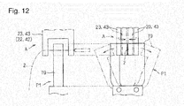
- the wire transport and gripping portions 79 it is possible to adopt a configuration in which a pair of gripping pieces are supported so as to be capable of being driven to be opened and closed as shown in FIG. 12 , for example.
- the wire transport mechanism portion 78 transports the terminal-equipped wire 2 in a state in which the longitudinally opposite ends of the terminal-equipped wire 2 are gripped by a pair of adjacent wire transport and gripping portions 79 toward the same direction along the horizontal direction and a longitudinally intermediate portion of the terminal-equipped wire 2 is suspended. Then, the wire transport and gripping portion 79 grips the wire at the downstream position of the cutting mechanism portion 74, ungrips the terminal-equipped wire 2 that has been manufactured through terminal crimping at the receiving position P1, and delivers the terminal-equipped wire 2 to the wire transfer device 10.
- the above-described operational control for the cutting-and-crimping device 70 is performed by a cutting-and-crimping control unit 62 constituted by a general microcomputer including a CPU, a ROM, a RAM, and so forth (see FIG. 1 ).
- the cutting-and-crimping control unit 62 outputs a signal indicating the presence of the terminal-equipped wire 2 at the receiving position P1 when the pair of wire transport and gripping portions 79 by which both wire ends of the terminal-equipped wire 2 are gripped are moved to the receiving position P1.
- Each of the wire holding bars 80 is a member on which a plurality of wire holding portions 82 capable of holding wire ends of the terminal-equipped wires 2 are disposed side by side in a row (see FIGS. 4, 5 ).
- the wire holding bar 80 is a member configured to be able to hold a plurality of terminal-equipped wires 2 that are respectively held by a plurality of wire holding portions 82 in a form in which the wire ends are in parallel.
- the wire holding bar 80 includes a bar body portion 85 that is formed in an elongated shape in the direction in which the plurality of wire holding portions 82 are arranged and that supports the plurality of wire holding portions 82.
- Each of the wire holding portions 82 constitutes a portion that holds a wire end of the terminal-equipped wire 2, and includes a pair of elastic gripping pieces 83 and an elastic gripping piece fixing portion 84.
- Each of the elastic gripping pieces 83 is a member that is formed, for example, by punching or bending a plate-shaped metal material or molding a synthetic resin material using a mold, and includes a flat portion on the proximal end side and a curved portion on the distal end side. More specifically, the flat portion is formed in a plate shape, and the curved portion is formed in a shape that extends continuously from the flat portion and is curved into an S-shape.
- the elastic gripping piece fixing portion 84 is a portion that supports the pair of elastic gripping pieces 83, and is formed of a synthetic resin or the like in a substantially rectangular parallelepiped shape as a whole.
- the elastic gripping piece fixing portion 84 is configured to be able to support the pair of elastic gripping pieces 83 in a state (back-to-back state) in which the flat portions of the elastic gripping pieces 83 overlap each other in an orientation in which the distal ends thereof are spaced apart from each other. More specifically, the elastic gripping piece fixing portion 84 is open on its one end face, and has a recessed portion into which the pair of elastic gripping pieces 83 can be fitted though that opening.
- the elastic gripping piece fixing portion 84 On the inner side of the interior of the elastic gripping piece fixing portion 84, a wall portion is formed that supports the pair of elastic gripping pieces 83 in a sandwiched manner in a state in which the flat portions of the elastic gripping pieces 83 are overlapped each other. Then, the elastic gripping piece fixing portion 84 supports the fitted pair of elastic gripping pieces 83 in a state in which portions in their curved portions that are near the distal ends are disposed in proximity to each other and the interval therebetween is smaller than the wire diameter of the terminal-equipped wire (this also includes a state in which the above-described portions are in contact with each other).
- the wire end of the terminal-equipped wire 2 between the pair of elastic gripping pieces 83 is held between the proximal locations in the curved portions of the pair of elastic gripping pieces 83 and the opening-side end face of the elastic gripping piece fixing portion 84.
- the wire holding portion 82 described above is merely an example, and it is possible to adopt a different configuration.
- the bar body portion 85 includes a body base portion 86 and a pair of end members 88.
- the body base portion 86 is formed in a bar shape (here, a prismatic bar shape), and the above-described plurality of wire holding portions 82 are supported in parallel on its one side surface extending along the longitudinal direction. More specifically, the body base portion 86 supports the plurality of wire holding portions 82 in a form in which the plurality of wire holding portions 82 are arranged in the direction in which the pair of elastic gripping pieces 83 face each other.
- the plurality of wire holding portions 82 are preferably supported by being fitted to the body base portion 86 through engagement between recesses and projections. In addition to this, it is also possible to adopt a configuration in which the wire holding portions 82 are separately fixed to the body base portion 86, for example, by screwing.
- the pair of end members 88 are portions that are fixed to the longitudinally opposite ends of the body base portion 86, for example, by screwing, and that retain and fix the plurality of wire holding portions 82 supported by the body base portion 86 so as to sandwich the wire holding portions 82 from both sides in the direction of their parallel arrangement.
- the wire holding bar transport device 90 is installed on the downstream side of the cutting-and-crimping device 70 that produces the terminal-equipped wire 2, and is configured to be able to transport the plurality of wire holding bars 80 along a circulation path (see FIGS. 1 to 3 ).
- the wire holding bar transport device 90 includes a plurality of bar supporting portions 92 and a circulation driving mechanism portion 94. More specifically, the wire holding bar transport device 90 circularly moves the plurality of bar supporting portions 92 that respectively support the plurality of wire holding bars 80 by the circulation driving mechanism portion 94 along the circulation path.
- the bar supporting portions 92 are portions that respectively support the plurality of wire holding bars 80, and are provided so as to be circularly movable along an annular circulation path.
- the circulation path is a path including an outwardly convex curved path and a linear path.
- the circulation path includes a pair of semicircular arc-shaped curved paths and a pair of linear paths that connect the pair of curved paths.
- the circulation path is set to be a path that passes through the set position P2 at which the terminal-equipped wire 2 is transferred to the wire holding bar 80 by the wire transfer device 10.
- Each of the bar supporting portions 92 is formed in a long groove that is open upward. That is, the bar supporting portion 92 is configured to support the wire holding bar 80 in an orientation in which the wire holding portions 82 (elastic gripping pieces 83) face upward, with the wire holding bar 80 being provided inside the bar supporting portion 92. However, as long as the bar supporting portion 92 is capable of supporting the wire holding bar 80 in an orientation in which the wire holding portions 82 face upward at least at the set position P2, the wire holding portions 82 may be supported in an orientation in which they face sideways at a position other than the set position P2. Additionally, the bar supporting portion 92 preferably has a fitting portion (not shown) capable of fitting to a part of the wire holding bar 80 through engagement between recesses and projections in order to prevent the supported wire holding bar 80 from coming off.
- the circulation driving mechanism portion 94 is a portion that circularly moves the plurality of bar supporting portions 92 along the circulation path.
- As the circulation driving mechanism portion 94 it is possible to adopt a configuration that includes a pair of gears 95, a circulating chain 96, and a driving portion 97.
- the pair of gears 95 are spur gears capable of rotating about the respective rotational shafts that are parallel to each other, and are supported relative to a base mount portion 98 at positions spaced away on substantially the same plane.
- One of the pair of gears 95 is rotationally driven by a driving portion 97 such as a motor.
- the annular circulating chain 96 is wound around the pair of gears 95, and extends on the circulation path (here, the circulation path is located on a plane substantially parallel to the horizontal plane). Then, as a result of the driving portion 97 being rotationally driven, the pair of gears 95 are rotated, and the circulating chain 96 is circularly rotated along the circulation path.
- the circulation driving mechanism portion 94 is not limited to the configuration including a combination of the pair of gears 95 and the circulating chain 96, and may have any configuration capable of circularly moving the plurality of bar supporting portions 92 along the circulation path, including, for example, a configuration including a combination of a pair of pulleys and a driving belt.
- the above-described plurality of bar supporting portions 92 are supported relative to the circulating chain 96. More specifically, the plurality of bar supporting portions 92 are provided so as to be capable of respectively supporting the plurality of wire holding bars 80 in an orientation in which the plurality of wire holding bars 80 extend outward of the circulation path. Additionally, the plurality of bar supporting portions 92 are provided at substantially equal intervals in the direction of extension of the circulating chain 96. For example, it is preferable that the plurality of bar supporting portions 92 are provided so as to be supported to the circulating chain 96 via a traveling portion capable of traveling on the base mount portion 98, and to move on the circulation path by movement of the traveling portion as a result of rotational movement of the circulating chain 96.
- the wire transfer device 10 is configured to transfer the terminal-equipped wire 2 disposed at the receiving position P1 on the downstream side of the terminal crimping mechanism portion 76 in the cutting-and-crimping device 70 to the wire holding bar 80 that has been moved to the set position P2 by the wire holding bar transport device 90 (see FIGS. 2 , 3 ).
- the wire transfer device 10 includes a first transfer mechanism portion 20 and a second transfer mechanism portion 40. Schematically, the wire transfer device 10 alternately transports the terminal-equipped wire 2 from the receiving position P1 to the set position P2 by the first transfer mechanism portion 20 and the second transfer mechanism portion 40, thus transferring the terminal-equipped wire 2 from the cutting-and-crimping device 70 to the wire holding bar 80.
- the first transfer mechanism portion 20 and the second transfer mechanism portion 40 are supported by a base mount portion 16 that is provided so as to extend along a direction connecting the receiving position P1 and the set position P2 by a column portion.
- the first transfer mechanism portion 20 includes a pair of first gripping mechanism portions 22, a pair of first advancing/retracting driving mechanism portions 26, and a pair of first reciprocating driving mechanism portions 32, and is configured to move the pair of first gripping mechanism portions 22 respectively gripping opposite wire ends of the terminal-equipped wire 2 by the pair of first advancing/retracting driving mechanism portions 26 and the pair of first reciprocating driving mechanism portions 32, respectively (see FIGS. 6 to 9 ).
- the first advancing/retracting driving mechanism portions 26 are drive mechanism portions that move the first gripping mechanism portions 22 on a plane orthogonal to the direction connecting the receiving position P1 and the set position P2.
- the first reciprocating driving mechanism portions 32 are drive mechanism portions that move the first advancing/retracting driving mechanism portions 26 (first gripping mechanism portions 22) along the direction connecting the receiving position P1 and the set position P2. More specifically, the first reciprocating driving mechanism portions 32 are configured to move the first advancing/retracting driving mechanism portions 26 in a first movement region R1 extending above the receiving position P1 and the set position P2 (see FIGS. 6 , 7 ).
- the pair of first gripping mechanism portions 22 are configured to be able to respectively grip and ungrip opposite wire ends of the terminal-equipped wire 2 (see FIG. 9 ). More specifically, the first gripping mechanism portions 22 are configured to be able to move the pair of gripping pieces 23 so as to be brought into contact with or separated from each other, and grip and sandwich the wire ends of the terminal-equipped wire 2 therebetween.
- the pair of gripping pieces 23 are substantially U-shaped.
- the pair of gripping pieces 23 grip the terminal-equipped wire 2 in a form in which the terminal-equipped wire 2 extends across the inside of the substantially U-shaped form in a direction connecting the opposing portions, and are capable of setting the terminal-equipped wire 2 to the wire holding portion 82 of the wire holding bar 80 and receiving the terminal-equipped wire 2 from the wire transport and gripping portion 79 of the wire transport mechanism portion 78 in a form of straddling the wire holding portion 82 and the wire transport and gripping portion 79 (see FIGS. 11 , 12 ). That is, the pair of gripping pieces 23 grip two locations of the wire ends of the terminal-equipped wire 2 extending on opposite sides of the wire holding portion 82 and the wire transport and gripping portion 79.
- the interval between the opposing portions of the substantially U-shaped form of the pair of gripping pieces 23 are set to be larger than the length of extension of the wire ends of the terminal-equipped wire 2 in the wire holding portion 82 and the wire transport and gripping portion 79.
- the first gripping mechanism portions 22 are configured to move the pair of gripping pieces 23 so as to be brought into contact with or separated from each other, for example, by an open/close driving mechanism 24 such as an air cylinder or an electromagnetic actuator.
- the open/close driving mechanism 24 moves one of the gripping pieces 23 so as to be brought into contact with or separated from the other gripping piece 23 (here, along the horizontal direction).
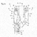
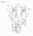
- the pair of first advancing/retracting driving mechanism portions 26 are configured to respectively move the pair of first gripping mechanism portions 22 between an advanced position A (see the first gripping mechanism portion 22 indicated by the dashed double-dotted line in FIG. 7 ) and a first retracted position C1 (see FIG. 6 ).
- the advanced position A is a position at which the terminal-equipped wire 2 disposed at the receiving position P1 can be received or the terminal-equipped wire 2 can be set to any one of the plurality of wire holding portions 82 of the wire holding bar 80 disposed at the set position P2.
- the pair of gripping pieces 23 of the first gripping mechanism portions 22 are provided in a form of straddling the wire holding portion 82 or the wire transport and gripping portion 79.
- the first retracted position C1 is a position that is retracted from the advanced position A, or more specifically, a position above the advanced position A. Also, at the first retracted position C1, the pair of gripping pieces 23 of the first gripping mechanism portions 22 are in a state in which they do not straddle the wire holding portion 82 or the wire transport and gripping portion 79.
- the first advancing/retracting driving mechanism portions 26 include an indirect upward/downward driving mechanism portion 27 and a delivery upward/downward driving portion 28.
- the indirect upward/downward driving mechanism portion 27 and the delivery upward/downward driving portion 28 are constituted by linear actuators such as air cylinders.
- the first advancing/retracting driving mechanism portions 26 directly move the first gripping mechanism portions 22 upward and downward by the delivery upward/downward driving portion 28, and indirectly move the first gripping mechanism portions 22 upward and downward by moving the delivery upward/downward driving portion 28 upward and downward by the indirect upward/downward driving mechanism portion 27.
- the indirect upward/downward driving mechanism portion 27 and the delivery upward/downward driving portion 28 are provided so as to perform linear driving along the vertical direction. That is, the first gripping mechanism portions 22 are moved in the direction connecting the receiving position P1 and the set position P2 on the first movement region R1 and in the up-down direction (see FIGS. 6 , 9 ).
- the delivery upward/downward driving portion 28 is configured to be able to move the first gripping mechanism portions 22 between the advanced position A and a preliminary retracted position B (see the first gripping mechanism portion 22 indicated by the solid line in the FIG. 6 ) between the advanced position A and the first retracted position C1, in a state in which the delivery upward/downward driving portion 28 is moved downward by the indirect upward/downward driving mechanism portion 27.
- the position to which the delivery upward/downward driving portion 28 in a state of being moved upward by the indirect upward/downward driving mechanism portion 27 has moved the first gripping mechanism portions 22 is the first retracted position C1.
- the pair of first reciprocating driving mechanism portions 32 are configured to respectively move the pair of first advancing/retracting driving mechanism portions 26 to a region on the receiving position P1 side and a region on the set position P2 side (see FIGS. 2 , 3 ).
- the region on the receiving position P1 side and the region on the set position P2 side are a region on the receiving position P1 side and a region on the set position P2 side in the first movement region R1 (and a movement region R2, which will be described below). That is, here, the first reciprocating driving mechanism portions 32 move up the first advancing/retracting driving mechanism portions 26 between a region above the receiving position P1 and a region above the set position P2.
- the pair of first reciprocating driving mechanism portions 32 respectively move the pair of first advancing/retracting driving mechanism portions 26 to positions corresponding to the pair of wire transport and gripping portions 79 where the pair of first gripping mechanism portions 22 grip the opposite wire ends of the terminal-equipped wire 2 at the receiving position P1 (see FIG. 3 ). Further, the pair of first reciprocating driving mechanism portions 32 respectively move the pair of first advancing/retracting driving mechanism portions 26 to positions corresponding to the two wire holding portions 82 to which the gripped terminal-equipped wire 2 is to be set, among the wire holding portions 82 at the set position P2 (see FIGS. 4, 5 ).
- the corresponding positions are positions at which the first gripping mechanism portions 22 are disposed directly above the wire transport and gripping portion 79 disposed at the receiving position P1 or the two wire holding portions 82 that are to be held, of the wire holding bars 80 disposed at the set position P2.
- the first reciprocating driving mechanism portions 32 include a guide rail 33, a pair of movement base portions 34, and a pair of reciprocating driving portions 36. More specifically, the first reciprocating driving mechanism portions 32 are configured to respectively move the pair of movement base portions 34 that are supported relative to the guide rail 33 so as to be movable in the longitudinal direction and that respectively support the pair of first advancing/retracting driving mechanism portions 26 by the pair of reciprocating driving portions 36 along the guide rail 33, thereby respectively moving the pair of first advancing/retracting driving mechanism portions 26.
- the guide rail 33 is formed in a long linear shape, and is provided in a form of extending along a direction (here, the horizontal direction) connecting the receiving position P1 and the set position P2 (see FIG. 3 ).
- the guide rail 33 is fixed to one side portion of the base mount portion 16. Additionally, the guide rail 33 is provided so as to extend linearly over a region including a position above the upstream wire transport and gripping portion 79 disposed at the receiving position P1 and a position above the wire holding portion 82 that is farthest away from the cutting-and-crimping device 70 among the wire holding bars 80 disposed at the set position P2.
- the pair of movement base portions 34 are supported in a form of being fitted to a single guide rail 33 through engagement between recesses and projections so as to be capable of moving to come into contact with or separate from each other along the longitudinal direction (see FIGS. 6 , 9 ).
- the pair of first advancing/retracting driving mechanism portions 26 are respectively fixed to the pair of movement base portions 34, for example, by screwing. This allows each of the pair of first advancing/retracting driving mechanism portions 26 to be supported so as to be movable along the guide rail 33.
- the reciprocating driving portions 36 include a pair of pulleys 37, motors 38 capable of rotationally driving one of the pulleys 37 in both forward and reverse directions, and annular driving belts 39 wound around the pair of pulleys 37 (see FIGS. 2 , 3 ).
- the pair of pulleys 37 are supported so as to be rotatable about an axis parallel to one side portion of the base mount portion 16 (here, along the horizontal direction).
- One (the pulley 37 on the wire holding bar transport device 90 side in FIGS. 2 and 3 ) of the pair of pulleys 37 is disposed so as to be rotatable by the motors 38.
- the motors 38 are also supported to the base mount portion 16.
- the movement base portions 34 are fixed to portions of the driving belts 39 in the direction of extension.
- the movement base portions 34 are fixed to lower portions of the driving belts 39 that extend along a direction connecting the receiving position P1 and the set position P2.
- the reciprocating driving portions 36 are configured to reciprocatingly move the movement base portions 34, which are fixed to the driving belts 39, between the receiving position P1 and the set position P2 by rotational driving performed by the motor 38 in both forward and reverse directions.
- a pair of the reciprocating driving portions 36 are provided in parallel at substantially the same height in order to respectively move the pair of movement base portions 34 along the guide rail 33 (see FIG. 2 ). That is, the positions of the pair of pulleys 37 and the driving belts 39 are set such that the pulleys 37 and the driving belts 39 operate on different parallel planes. More specifically, the pair of pulleys 37, the motors 38, and the driving belts 39 in the pair of reciprocating driving portions 36 are displaced in the direction connecting the receiving position P1 and the set position P2 in order to prevent interference between the pair of pulleys 37 and between the motors 38.
- the pair of first advancing/retracting driving mechanism portions 26 are respectively supported by the pair of movement base portions 34 that are respectively fixed to the pair of driving belts 39 such that the first advancing/retracting driving mechanism portions 26 are disposed side by side along the direction connecting the receiving position P1 and the set position P2 (see FIG. 9 ).
- the pair of first gripping mechanism portions 22 are also disposed side by side along the direction connecting the receiving position P1 and the set position P2.
- the second transfer mechanism portion 40 includes second gripping portions 42, second advancing/retracting driving mechanism portions 46, and second delivery movement driving portions 52 (see FIGS. 6 to 8 , 10 ). More specifically, the second transfer mechanism portion 40 is configured to move a pair of second gripping mechanism portions 42 that respectively grip opposite wire ends of the terminal-equipped wire 2 by a pair of second advancing/retracting driving mechanism portions 46 and a pair of second reciprocating driving mechanism portions 52.
- the second advancing/retracting driving mechanism portions 46 are drive mechanism portions that move the second gripping mechanism portions 42 on a plane orthogonal to the direction connecting the receiving position P1 and the set position P2.
- the second reciprocating driving mechanism portions 52 are drive mechanism portions that move the second advancing/retracting driving mechanism portions 46 (second gripping mechanism portions 42) along the direction connecting the receiving position P1 and the set position P2. More specifically, the second reciprocating driving mechanism portions 52 are configured to move the second advancing/retracting driving mechanism portions 46 in a second movement region R2 extending laterally in parallel with the first movement region R1 (see FIGS. 2 , 6 ).
- the pair of second gripping mechanism portions 42 are configured to be able to grip and ungrip the opposite wire ends, respectively, of the terminal-equipped wire 2. More specifically, the second gripping mechanism portions 42 are configured to be able to move the pair of gripping pieces 43 so as to be brought into contact with or separated from each other, and grip and sandwich the wire ends of the terminal-equipped wire 2 therebetween.
- the pair of gripping pieces 43 are substantially U-shaped, as with the pair of gripping pieces 23.
- the first gripping mechanism portions 42 are configured to move the pair of gripping pieces 43 so as to be brought into contact with or separated from each other by an open/close driving mechanism 44.
- the pair of second advancing/retracting driving mechanism portions 46 are configured to respectively move the pair of second gripping mechanism portions 42 between an advanced position A (see the second gripping mechanism portion 42 indicated by the dashed double-dotted line in FIG. 6 ) and a second retracted position C2 (see FIG. 7 ) that is retracted from the advanced position A.
- the advanced position A is the same position as the advanced position A of the first gripping mechanism portions 22.
- the second retracted position C2 is a position that is obliquely above the advanced position A and at which the second gripping mechanism portions 42 do not straddle the wire holding portions 82 or the wire transport and gripping portions 79.
- the second retracted position C2 is a position different from the first retracted position C1 of the first gripping mechanism portions 22.
- FIG. 8 shows a state in which the first gripping mechanism portion 22 and the second gripping mechanism portion 42 disposed at the first retracted position C1 or the second retracted position C2, respectively.
- the second advancing/retracting driving mechanism portions 46 are configured to move the second gripping mechanism portions 42 along a path including a linear path extending obliquely upward between the advanced position A on the first movement region R1 and the second retracted position C2 on the second movement region R2. More specifically, the second advancing/retracting driving mechanism portions 46 include an indirect upward/downward driving mechanism portion 47 and a delivery upward/downward driving portion 48. Also, the second advancing/retracting driving mechanism portions 46 directly move the second gripping mechanism portions 42 upward and downward by the delivery upward/downward driving portion 48, and indirectly move the second gripping mechanism portions 42 upward and downward by moving the delivery upward/downward driving portion 48 upward and downward by the indirect upward/downward driving mechanism portion 47.
- the indirect upward/downward driving mechanism portion 47 is provided so as to move the delivery upward/downward driving portion 48 obliquely upward and downward between a lowered position on the first movement region R1 and a raised position that is on the second movement region R2 and is obliquely above the lowered position.
- the lowered position is a position directly above the wire transport and gripping portion 79 disposed at the receiving position P1 and a position directly above the wire holding bar 80 disposed at the set position P2.
- the delivery upward/downward driving portion 48 is provided so as to linearly drive the second gripping mechanism portions 42 along the vertical direction.
- the indirect upward/downward driving mechanism portion 47 and the delivery upward/downward driving portion 48 described above are constituted by linear actuators such as air cylinders.
- the delivery upward/downward driving portion 48 is configured to be able to move the second gripping mechanism portions 42 between the advanced position A and a preliminary retracted position B (see the second gripping mechanism portion 42 indicated by the solid line in FIG. 6 ) located above the advanced position A in a state in which the delivery upward/downward driving portion 48 is moved downward from the raised position to the lowered position, which is obliquely therebelow, by the indirect upward/downward driving mechanism portion 47.
- the preliminary retracted position B of the second gripping mechanism portions 42 is the same position as the preliminary retracted position B of the first gripping mechanism portions 22 (however, it may be a different position).
- a position to which the delivery upward/downward driving portion 48 in a state of being moved upward from the lowered position to the raised position, which is obliquely thereabove, by the indirect upward/downward driving mechanism portion 47 has moved the second gripping mechanism portions 42 upward is the second retracted position C2.
- the pair of second reciprocating driving mechanism portions 52 are configured to respectively move the pair of second advancing/retracting driving mechanism portions 46 between a region on the receiving position P1 side and a region on the set position P2 side in the second movement region R2 (see FIGS. 2 , 3 ). More specifically, the pair of second reciprocating driving mechanism portions 52 respectively move the pair of second advancing/retracting driving mechanism portions 46 to positions corresponding to the pair of wire transport and gripping portions 79 where the pair of second gripping mechanism portions 42 grip the opposite wire ends of the terminal-equipped wire 2 at the receiving position P1.
- the pair of second reciprocating driving mechanism portions 52 respectively move the pair of second advancing/retracting driving mechanism portions 46 to positions corresponding to the two wire holding portions 82 to which the griped terminal-equipped wire 2 is to be set, among the wire holding bars 80 disposed at the set position P2.
- the second reciprocating driving mechanism portions 52 include a guide rail 53, a pair of movement base portions 54, and a pair of reciprocating driving portions 56. More specifically, the second reciprocating driving mechanism portions 52 are configured to respectively move the pair of second advancing/retracting driving mechanism portions 46 by respectively moving the pair of movement base portions 54 that are supported relative to the guide rails 53 so as to be movable in the longitudinal direction and that respectively support the pair of first advancing/retracting driving mechanism portions 56 by the pair of reciprocating driving portions 56 along the guide rail 53.
- the guide rail 53 is formed in a long linear shape, and is provided in a form of extending along the direction connecting the receiving position P1 and the set position P2 (here, the horizontal direction).
- the guide rail 53 is fixed to the other side portion of the base mount portion 16 in a form of extending in parallel with the guide rail 33. Additionally, the guide rail 53 is provided so as to extend in a region including a position above the receiving position P1 to a position above the wire holding portion 82 of the wire holding bar 80 at the set position P2 that is farthest away from the cutting-and-crimping device 70.
- the pair of movement base portions 54 are supported in a form in which they fit to a single guide rail 53 through engagement of recesses and projections so as to be capable of moving to come into contact with or separate from each other along the longitudinal direction.
- the pair of first advancing/retracting driving mechanism portions 46 are fixed to the pair of movement base portions 54. This allows each of the pair of first advancing/retracting driving mechanism portions 46 to be supported so as to be movable along the guide rail 53.
- the reciprocating driving portions 56 include a pair of pulleys 57, motors 58 capable of rotationally driving one of the pulleys 57 in both forward and reverse directions, and annular driving belts 59 wound around the pair of pulleys 57.
- the pair of pulleys 57 are supported so as to be rotatable about an axis that is parallel to the other side portion of the base mount portion 16 (here, along the horizontal direction).
- One (the pulley 57 on the wire holding bar transport device 90 side in FIG. 2 ) of the pair of pulleys 57 is disposed so as to be able to be rotationally driven by the motors 58.
- the motors 58 are also supported to the base mount portion 16.
- the movement base portions 54 are fixed to portions of the driving belts 59 in the direction of extension.
- the movement base portions 54 are fixed to lower portions of the driving belts 59 that extend along the direction connecting the receiving position P1 and the set position P2.
- the reciprocating driving portions 56 are configured to reciprocatingly move the movement base portions 54 fixed to the driving belts 59 between the receiving position P1 and the set position P2 by rotational driving performed by the motors 58 in both forward and reverse directions.
- a pair of the reciprocating driving portions 56 are provided in parallel at substantially the same height position. That is, the positions of the pair of pulleys 57 and the driving belts 59 are set such that the pulleys 57 and the driving belts 59 operate on different parallel planes. More specifically, the pair of pulleys 57, the motors 58, and the driving belts 59 in the pair of reciprocating driving portions 56 are displaced in the direction connecting the receiving position P1 and the set position P2 in order to prevent interference between the pair of pulleys 57 and between the motors 58.
- the pair of second advancing/retracting driving mechanism portions 46 are respectively supported by the pair of movement base portions 54 that are respectively fixed to the pair of driving belts 59 so as to be disposed side by side along the direction connecting the receiving position P1 and the set position P2.
- the pair of second gripping mechanism portions 42 are also disposed side by side along the direction connecting the receiving position P1 and the set position P2.
- the first reciprocating driving mechanism portions 32 and the second reciprocating driving mechanism portions 52 are configured to cause the first advancing/retracting driving mechanism portions 26 and the second advancing/retracting driving mechanism portions 46 to pass each other in a state in which at least one of the first gripping mechanism portions 22 and the second gripping mechanism portions 42 is moved to the first retracted position C1 or the second retracted position C2 (see FIGS. 6 to 8 ). Also, the first reciprocating driving mechanism portions 32 and the second reciprocating driving mechanism portions 52 alternately move the first advancing/retracting driving mechanism portions 26 and the second advancing/retracting driving mechanism portion 46 to the region on the receiving position P1 side and the region on the set position P2 side.
- the second transfer mechanism portion 40 sets the terminal-equipped wire 2 to the wire holding bar 80 at the set position P2. While the second transfer mechanism portion 40 is receiving the terminal-equipped wire 2 at the receiving position P1, the first transfer mechanism portion 20 sets the terminal-equipped wire 2 to the wire holding bar 80 at the set position P2.
- the above-described operational control for the wire transfer device 10 is performed by a transport control unit 60 constituted by a general microcomputer including a CPU, a ROM, a RAM, and so forth (see FIG. 1 ).
- a transport control unit 60 When a signal indicating the presence of the terminal-equipped wire 2 at the receiving position P1 is output from the cutting-and-crimping control unit 62, the transport control unit 60 performs the operational control for the various driving portions of the first transfer mechanism portion 20 and the second transfer mechanism portion 40 in the wire transfer device 10, in order to receive and set the terminal-equipped wire 2 with this timing.
- the operational control for the wire holding bar transport device 90 is also performed by the above-described transport control unit 60.
- the transport control unit 60 controls the transport timing of the wire holding bars 80 such that a preset number of terminal-equipped wires 2 are transferred to the wire holding bars 80, in conjunction with the cutting-and-crimping control unit 62 and the like.
- a pair of wire transport and gripping portions 79 that grip opposite wire ends of a terminal-equipped wire 2 manufactured by the cutting-and-crimping device 70 are disposed at the receiving position P1.
- a wire holding bar 80 including a wire holding portion 82 on which no terminal-equipped wire 2 is held is disposed at the set position P2 by the wire holding bar transport device 90.
- the pair of first reciprocating driving mechanism portions 32 support the first advancing/retracting driving mechanism portions 26 above the wire transport and gripping portions 79 disposed at the receiving position P1
- the pair of second reciprocating driving mechanism portions 52 support the second advancing/retracting driving mechanism portions 46 above predetermined two wire holding portions 82 of the wire holding bar 80 disposed at the set position P2.
- the pair of first advancing/retracting driving mechanism portions 26 and the pair of second advancing/retracting driving mechanism portions 46 support the first gripping mechanism portions 22 and the second gripping mechanism portions 42 at the first retracted position C1 or the second retracted position C2 (see FIG. 8 ).
- the pair of gripping pieces 23 of the first gripping mechanism portions 22 are open, and the pair of gripping pieces 23 of the second gripping mechanism portions are closed with the wire ends of the terminal-equipped wire 2 interposed therebetween.
- the delivery upward/downward driving portion 28 is moved downward by the indirect upward/downward driving mechanism portion 27 (see FIG. 7 ). Thereby, the first gripping mechanism portions 22 are moved from the first retracted position C1 to the preliminary retracted position B.
- the first gripping mechanism portions 22 are moved downward by the delivery upward/downward driving portion 28 (see FIG. 7 ). Thereby, the first gripping mechanism portions 22 are moved from the preliminary retracted position B to the advanced position A.
- the pair of gripping pieces 23 are moved close to each other (closed) by the open/close driving mechanism 24 (see FIG. 12 ).
- the interval between the pair of gripping pieces 23 is set to be the same as or smaller (here, slightly smaller) than the diameter of the wire end of the terminal-equipped wire 2.
- the first gripping mechanism portions 22 grip the wire ends of the terminal-equipped wire 2 gripped by the wire transport and gripping portions 79.
- the wire transport and gripping portions 79 are caused to ungrip the terminal-equipped wire 2.
- the first gripping mechanism portions 22 are moved upward by the delivery upward/downward driving portion 28. Thereby, the first gripping mechanism portions 22 are moved from the advanced position A to the preliminary retracted position B.
- the delivery upward/downward driving portion 28 is moved upward by the indirect upward/downward driving mechanism portion 27.
- the first gripping mechanism portions 22 are moved from the preliminary retracted position B to the first retracted position C1.
- the receiving step for the terminal-equipped wire 2 performed by the first transfer mechanism portion 20 is completed.
- the setting step for the terminal-equipped wire 2 is performed by the second transfer mechanism portion 40.
- the delivery upward/downward driving portion 48 is moved downward by the indirect upward/downward driving mechanism portion 47 (see FIG. 6 ).
- the second gripping mechanism portions 42 are moved from the second retracted position C2 to the preliminary retracted position B.
- the second gripping mechanism portions 42 are moved downward by the delivery upward/downward driving portion 48 (see FIG. 6 ). Thereby, the second gripping mechanism portions 42 are moved from the preliminary retracted position B to the advanced position A.
- the terminal-equipped wire 2 gripped by the second gripping mechanism portions 42 is held by the wire holding portion 82 of the wire holding bar 80. More specifically, by the advancing operation of the pair of gripping pieces 43, a part of the wire end of the terminal-equipped wire 2 that extends across the inside of the opposing portions of the gripping pieces 43 is sandwiched between the pair of elastic gripping pieces 83 of the wire holding portion 82 that are provided in the inside of the opposing portions (see FIGS. 5 , 11 ).
- the pair of gripping pieces 43 are moved away from each other (opened) by the open/close driving mechanism 44.
- the interval between the pair of gripping pieces 43 is set to be larger than the diameter of the wire end of the terminal-equipped wire 2.
- the second gripping mechanism portions 42 ungrip the wire ends of the terminal-equipped wire 2.
- the second gripping mechanism portions 42 are moved upward by the delivery upward/downward driving portion 48. Thereby, the second gripping mechanism portions 42 are moved from the advanced position A to the preliminary retracted position B.
- the delivery upward/downward driving portion 48 is moved upward by the indirect upward/downward driving mechanism portion 47.
- the second gripping mechanism portions 42 are moved from the preliminary retracted position B to the second retracted position C2.
- FIGS. 6 and 7 show how the first gripping mechanism portions 22 and the second gripping mechanism portions 42 are alternately moved to the advanced position A and the first retracted position C1 or the second retracted position C2, this is shown for the sake of convenience of description. Actually, both the first gripping mechanism portions 22 and the second gripping mechanism portions 42 are moved to the advanced position A in the region on the receiving position P1 side or the region on the set position P2 side.
- the transport step performed by the first transfer mechanism portion 20 and the second transfer mechanism portion 40 is carried out.
- the first advancing/retracting driving mechanism portions 26 are moved by the first reciprocating driving mechanism portions 32 from the region on the receiving position P1 side to the region on the set position P2 side in the first path R1.
- the second advancing/retracting driving mechanism portions 46 are moved by the second reciprocating driving mechanism portions 52 from the region on the set position P2 side to the region on the receiving position P1 side in the second path R2.
- the first gripping mechanism portions 22 and the second gripping mechanism portions 42 laterally pass each other in a state in which they are at the first retracted position C1 or the second retracted position C2 (see FIG. 8 ).
- the first advancing/retracting driving mechanism portions 26 and the second advancing/retracting driving mechanism portions 46 can pass each other.
- the second gripping mechanism portions 42 pass through below the first gripping mechanism portions 22 (see FIG. 6 ).
- the above-described state is a state in which the delivery upward/downward driving portion 48 is moved to the lowered position by the indirect upward/downward driving mechanism portion 47, and the second gripping mechanism portions 42 are moved to the lowered position by the delivery upward/downward driving portion 48.
- the first gripping mechanism portions 22 are at the preliminary retracted position B and the second gripping mechanism portions 42 are at the second retracted position C2
- the first gripping mechanism portions 22 and the second gripping mechanism portions 42 laterally pass each other (see FIG. 7 ).
- the first gripping mechanism portions 22 and the second gripping mechanism portions 42 are alternately moved between the region on the receiving position P1 side and the region on the set position P2 side in a state in which either the first gripping mechanism portions 22 or the second gripping mechanism portions 42 that grip the terminal-equipped wire 2 and are moved from the region on the receiving position P1 side to the region on the set position P2 side may be disposed at the preliminary retracted position B, and the other gripping mechanism portions may be disposed at the first retracted position C1 or the second retracted position C2 (see FIGS. 6 , 7 ).
- the other gripping mechanism portions do not need to be moved upward from the preliminary retracted position B.
- the pair of first reciprocating driving mechanism portions 32 move the first advancing/retracting driving mechanism portions 26 to a position at which the first gripping mechanism portions 22 are disposed above the wire holding portion 82 that is to be set and is different from the one that was set the previous time, of the wire holding bar 80 disposed at the set position P2.
- the pair of second reciprocating driving mechanism portions 52 move the second advancing/retracting driving mechanism portions 46 to a position at which the second gripping mechanism portions 42 are disposed above the pair of wire transport and gripping portions 79 disposed at the receiving position P1.
- the setting step for the terminal-equipped wire 2 received in the receiving step is performed by the first transfer mechanism portion 20, and the receiving step for the terminal-equipped wire is performed by the second transfer mechanism portion 40.
- the first gripping mechanism portions 22 are moved to the advanced position A by the pair of first advancing/retracting driving mechanism portions 26, and are held by the wire holding portions 82 of the wire holding bars 80. Then, the gripping of the wire ends of the terminal-equipped wires 2 by the first gripping mechanism portions 22 is released, and the first gripping mechanism portions 22 are again moved to the first retracted position C1 by the pair of first advancing/retracting driving mechanism portions 26. Thereby, the setting step for the terminal-equipped wire 2 performed by the first transfer mechanism portion 20 is completed.
- the second gripping mechanism portions 42 are moved to the advanced position A by the pair of second advancing/retracting driving mechanism portions 26, and the wire ends of the terminal-equipped wires 2 that are gripped by the wire transport and gripping portions 79 are gripped by the second gripping mechanism portions 42. Then, the second gripping mechanism portions 42 are again moved to the second retracted position C2 by the pair of second advancing/retracting driving mechanism portions 46. Thereby, the receiving step for the terminal-equipped wire 2 by the second transfer mechanism portion 20 is completed.
- the transport step performed by the first transfer mechanism portion 20 and the second transfer mechanism portion 40 is carried out. That is, the first advancing/retracting driving mechanism portions 26 are moved by the first reciprocating driving mechanism portions 32 from the region on the set position P2 side to the region on the receiving position P1 side in the first path R1. Simultaneously, the second advancing/retracting driving mechanism portions 46 are moved by the second reciprocating driving mechanism portions 52 from the region on the receiving position P1 side to the region on the set position P2 side in the second path R2.
- the terminal-equipped wire 2 can be continuously transferred. Then, when a wire holding bar 80 is fully occupied, the next wire holding bar 80 may be moved to the set position P2 by the wire holding bar transport device 90, and the terminal-equipped wire 2 may be transferred to this wire holding bar 80.
- the first reciprocating driving mechanism portions 32 and the second reciprocating driving mechanism portions 52 alternately move the first advancing/retracting driving mechanism portions 26 and the second advancing/retracting driving mechanism portions 46 to the region on the receiving position P1 side and the region on the set position P2 side in a state in which at least one of the first gripping mechanism portions 22 and the second gripping mechanism portions 42 is moved to the first retracted position C1 or the second retracted position C2.
- the other gripping mechanism portions can perform the operation of setting the terminal-equipped wire 2 to the wire holding portion 82 of the wire holding bar 80 on the set position P2 side.
- This makes it possible to transfer the terminal-equipped wire 2 at twice the speed compared with the speed when only one transfer mechanism portion is provided, thus further improving the transfer efficiency for the terminal-equipped wire 2.
- the advanced positions A1 of the first gripping mechanism portions 22 and the second gripping mechanism portions 42 are the same, it is possible to improve the transfer efficiency for the terminal-equipped wire 2 without changing the configurations of the cutting-and-crimping device 70 and the wire holding bar transport device 90.
- the movement distance of the second gripping mechanism portions 42 can be reduced. This also contributes to space saving for the wire transfer device 10 itself.
- the second advancing/retracting driving mechanism portions 46 include the delivery upward/downward driving portion 48 that moves the second gripping mechanism portions 42 upward and downward, and the indirect upward/downward driving mechanism portion 47 that moves the delivery upward/downward driving portion 48 obliquely upward and downward between the lowered position on the first movement region R1 and the raised position that is on the second movement region R2 and is obliquely above the lowered position
- the second gripping mechanism portions 42 are set to be able to pass through below the first gripping mechanism portions 22 that have moved to the first retracted position C1 in a state in which the delivery upward/downward driving portion 48 is moved to the lowered position by the indirect upward/downward driving mechanism portion 47, it is possible to cause the first gripping mechanism portions 22 and the second gripping mechanism portions 42 to pass each other between the region on the receiving position P1 side and the region on the set position P2 side as long as the second gripping mechanism portions 42 are moved upward by the delivery upward/downward driving portion 48, even if the delivery upward/downward driving portion 48 remains at the lowered position.
- first reciprocating driving mechanism portions 32 and the second reciprocating driving mechanism portions 52 alternately move the first advancing/retracting driving mechanism portions 26 and the second advancing/retracting driving mechanism portions 46 in the region on the receiving position P1 side and the region on the set position P2 side, it is possible to allow the receiving operation and the setting operation for the terminal-equipped wire 2 to proceed simultaneously, thus further improving the transfer efficiency.
- the first transfer mechanism portion 20 has thus been described, taking, as an example, a case where the first gripping mechanism portions 22 are moved only in the up-down direction, it is also possible to adopt a configuration in which the first gripping mechanism portions 22 are moved obliquely as in the second transfer mechanism portion 40.
- the first transfer mechanism portion 20 may be configured to move the delivery upward/downward driving portion 28 in an oblique direction by an indirect upward/downward driving mechanism portion that is provided along the oblique direction.
- the second transfer mechanism portion 40 has been described, taking, as an example, a case where the delivery upward/downward driving portion 48 is moved in an oblique direction by the indirect upward/downward driving mechanism portion 47, the present invention is not limited thereto. That is, as long as the second transfer mechanism portion 40 is capable of moving the second gripping mechanism portions 42 between the advanced position A and the second retracted position C2, the second transfer mechanism portion 40 may include an indirect upward/downward driving mechanism portion that moves the delivery upward/downward driving portion 48 in the horizontal direction. Also, the second transfer mechanism portion 40 may be configured such that the indirect upward/downward driving mechanism portion moves the delivery upward/downward driving portion 48 in the vertical direction. In this case, however, it is necessary to configure the first advancing/retracting driving mechanism portions such that the first gripping mechanism portions 22 are also moved in an oblique direction or the horizontal direction.
- first reciprocating driving mechanism portions 32 and the second reciprocating driving mechanism portions 52 have been described, taking, as an example, a case where they are each composed of a guide rail, movement base portions, a pairs of pulleys, motors, and driving belts, the present invention is not limited thereto. That is, as long as the first reciprocating driving mechanism portions 32 and the second reciprocating driving mechanism portions 52 are mechanisms capable of linearly moving the first advancing/retracting driving mechanism portions 26 or the second advancing/retracting driving mechanism portions 46 along the first movement region R1 or the second movement region R2, it is possible to use linear actuators such as air cylinders.
- the operations of the wire transfer device 10 have been described, taking, as an example, a case where the receiving step or the setting step performed by the first transfer mechanism portion 20 and the setting step or the receiving step performed by the second transfer mechanism portion 40 proceed simultaneously, the two steps performed by the two components may be performed with shifted timing. That is, when the first transfer mechanism portion 20 and the second transfer mechanism portion 40 operate so as to cause the first gripping mechanism portions 22 and the second gripping mechanism portions 42 to pass each other, it is possible to achieve improved transfer efficiency than when the transfer is performed by one transfer mechanism portion.
- the reciprocating movement of the first gripping mechanism portions 22 and the second gripping mechanism portions 42 in the region on the receiving position P1 side and the region in the set position P2 side is performed alternately by the first transfer mechanism portion 20 and the second transfer mechanism portion 40, and the setting step and the receiving step proceed simultaneously.
- wire transfer device 10 has been described in detail thus far, the foregoing description is in all aspects illustrative and the present invention is not limited thereto. It will be appreciated that numerous modifications not illustrated herein can be made without departing from the scope of the present invention.
Landscapes
- Engineering & Computer Science (AREA)
- Manufacturing & Machinery (AREA)
- Physics & Mathematics (AREA)
- Thermal Sciences (AREA)
- Manufacturing Of Electrical Connectors (AREA)
Abstract
Description
- The present invention relates to a technique for transporting a wire in a manufacturing process of a wire harness.
- Wire harnesses are manufactured through a cutting-and-crimping step, a temporary binding step, and an assembly step, for example. The cutting-and-crimping step is a step of cutting wires into a predetermined length, and crimping terminals to ends of the wires to manufacture terminal-equipped wires (i.e. wires equipped with terminals). The temporary binding step is a step of binding a plurality of terminal-equipped wires or inserting the terminals of a plurality of terminal-equipped wires into connectors to produce temporary bundles. The assembly step is a step of assembling the plurality of terminal-equipped wires and the plurality of temporary bundles into a predetermined wiring configuration to manufacture a wire harness.
- During such a wire harness manufacturing process, a plurality of types of terminal-equipped wires may occasionally be held by wire holding bars in units of temporary bundles at the time of supplying terminal-equipped wires to the temporary binding step. As an example of a device used for transferring the plurality of types of terminal-equipped wires from the cutting-and-crimping step to the wire holding bars, Patent Document 1 discloses a terminal-equipped wire transfer mechanism portion.
- The terminal-equipped wire transfer mechanism portion is a device that transfers terminal-equipped wires from a terminal crimping device that crimps terminals to ends of wires that have been cut into a measured length, toward wire holding bars on the side of a wire holding bar transport device that transports a plurality of wire holding bars. More specifically, the terminal-equipped wire transfer mechanism portion includes a pair of transfer gripping portions capable of gripping and ungripping ends of the terminal-equipped wires, and a transfer gripping portion movement driving portion that drives movement of the pair of transfer gripping portions. The transfer gripping portion movement driving portion is configured such that the pair of transfer gripping portions are respectively provided on two base plates, with each of the base plates being supported by a horizontal guide so as to be horizontally movable between the wire holding bars and a wire receiving position, and the pair of transfer gripping portions are moved along the horizontal guides by different transfer driving portions.
- Patent Document 1: JP 2010-287369A
- However, with the terminal-equipped wire transfer mechanism portion described in Patent Document 1, it is necessary to reciprocate the pair of transfer gripping portions once in order to set one terminal-equipped wire to one wire holding bar. Accordingly, it has been difficult to increase the transfer efficiency of terminal-equipped wires over the motor performance.
- Therefore, it is an object of the present invention to improve the transfer efficiency of terminal-equipped wires.
- A wire transfer device according to a first aspect is a wire transfer device that transfers a terminal-equipped wire that is manufactured in a cutting-and-crimping device and is disposed at a receiving position to a wire holding bar that is disposed at a set position and on which a plurality of wire holding portions capable of holding a wire end of the terminal-equipped wire are provided in a row, including: a first transfer mechanism portion and a second transfer mechanism portion, wherein the first transfer mechanism portion includes: a pair of first gripping mechanism portions capable of respectively gripping and ungripping opposite wire ends of the terminal-equipped wire; a pair of first advancing/retracting driving mechanism portions that respectively move the pair of first gripping mechanism portions between an advanced position and a first retracted position, the advanced position being a position at which the terminal-equipped wire disposed at the receiving position can be received or the terminal-equipped wire can be set to at least one of the plurality of wire holding portions of the wire holding bar disposed at the set position, and the first retracted position being a position retracted from the advanced position; and a pair of first reciprocating driving mechanism portions that respectively move the pair of first advancing/retracting driving mechanism portions between a region on the receiving position side and a region on the set position side, the second transfer mechanism portion includes: a pair of second gripping mechanism portions capable of respectively gripping and ungripping the opposite wire ends of the terminal-equipped wire; a pair of second advancing/retracting driving mechanism portions that respectively move the pair of second gripping mechanism portions between the advanced position and a second retracted position that is retracted from the advanced position and is different from the first retracted position; and a pair of second reciprocating driving mechanism portions that respectively move the pair of second advancing/retracting driving mechanism portions between the region on the receiving position side and the region on the set position side in a movement region that is in parallel with a movement region of the first advancing/retracting driving mechanism portions by the first reciprocating driving mechanism portions, and the first reciprocating driving mechanism portions and the second reciprocating driving mechanism portions cause the first advancing/retracting driving mechanism portions and the second advancing/retracting driving mechanism portions to pass each other in a state in which at least one of the first gripping mechanism portions and the second gripping mechanism portions is moved to the first retracted position or the second retracted position.
- A second aspect is the wire transfer device according to the first aspect, wherein the first reciprocating driving mechanism portions are configured to move the first advancing/retracting driving mechanism portions in a first movement region extending above the receiving position and the set position, the second reciprocating driving mechanism portions are configured to move the second advancing/retracting driving mechanism portions in a second movement region extending laterally in parallel with the first movement region, and the second advancing/retracting driving mechanism portions move the second gripping mechanism portions along a path including a linear path extending obliquely upward from the advanced position in the first movement region to the second retracted position that is in the second movement region and is obliquely above the advanced position.
- A third aspect is the wire transfer device according to the second aspect, wherein the second advancing/retracting driving mechanism portions include: a delivery upward/downward driving portion that moves the second gripping mechanism portions upward and downward; and an indirect upward/downward driving mechanism portion that moves the delivery upward/downward driving portion obliquely upward or downward between a lowered position in the first movement region and a raised position that is in the second movement region and is obliquely above the lowered position.
- A fourth aspect is the wire transfer device according to the third aspect, wherein the second gripping mechanism portions are set to be able to pass through below the first gripping mechanism portions that have been moved to the first retracted position in a state in which the delivery upward/downward driving portion is moved to the lowered position by the indirect upward/downward driving mechanism portion.
- A fifth aspect is the wire transfer device according to any one of the first to fourth aspects, wherein the first reciprocating driving mechanism portions and the second reciprocating driving mechanism portions alternately move the first advancing/retracting driving mechanism portions and the second advancing/retracting driving mechanism portions between the region on the receiving position side and the region on the set position side.
- With the wire transfer device according to the first aspect, the first reciprocating driving mechanism portions and the second reciprocating driving mechanism portions cause the first advancing/retracting driving mechanism portions and the second advancing/retracting driving mechanism portions to pass each other in a state in which at least one of the first gripping mechanism portions and the second gripping mechanism portions is moved to the first retracted position or the second retracted position. Accordingly, while either the first gripping mechanism portions or the second gripping mechanism portions are performing the operation of receiving the terminal-equipped wire on the receiving position side, the other gripping mechanism portions can perform the operation of setting the terminal-equipped wire to the wire holding portion of the wire holding bar on the set position side. This makes it possible to further improve the transfer speed for the terminal-equipped wire.
- With the wire transfer device according to the second aspect, the second advancing/retracting driving mechanism portions move the second gripping mechanism portions along a path including a linear path extending obliquely upward from the advanced position in the first movement region to which the first advancing/retracting driving mechanism portions are moved to the second retracted position that is in the second movement region to which the second advancing/retracting driving mechanism portions are moved and is obliquely above the advanced position. Accordingly, the movement distance of the second gripping mechanism portions can be reduced.
- With the wire transfer device according to the third aspect, the second advancing/retracting driving mechanism portions includes the delivery upward/downward driving portion that moves the second gripping mechanism portions upward and downward, and the indirect upward/downward driving mechanism portion that moves the delivery upward/downward driving portion obliquely upward and downward between the lowered position in the first movement region and the raised position that is in the second movement region and is obliquely above the lowered position. Accordingly, it is possible to further simplify the configuration for moving the delivery upward/downward driving portion to the lowered position in the first movement region.
- With the wire transfer device according to the fourth aspect, the second gripping mechanism portions are set to be able to pass through below the first gripping mechanism portions that have moved to the first retracted position in a state in which the delivery upward/downward driving portion is moved to the lowered position by the indirect upward/downward driving mechanism portion. Accordingly, it is possible to cause the first gripping mechanism portions and the second gripping mechanism portions to pass each other between the region on the receiving position side and the region on the set position side as long as the second gripping mechanism portions are moved upward by the delivery upward/downward driving portion, even if the delivery upward/downward driving portion remains at the lowered position. This can reduce the number of times of driving performed by the indirect upward/downward driving mechanism portion, thus contributing to a reduced driving cost and a longer durable period.
- With the wire transfer device according to the fifth aspect, the first reciprocating driving mechanism portions and the second reciprocating driving mechanism portions alternately move the first advancing/retracting driving mechanism portions and the second advancing/retracting driving mechanism portions in the region on the receiving position side and the region on the set position side. Accordingly, it is possible to allow the receiving operation and the setting operation for the terminal-equipped wire to proceed simultaneously, thus further improving the transfer efficiency.
-
-
FIG. 1 is a diagram showing a relationship between a cutting-and-crimping device, a wire transfer device, and a wire holding bar transport device. -
FIG. 2 is a plan view of the wire transfer device. -
FIG. 3 is a side view of the wire transfer device. -
FIG. 4 is a side view of a wire holding bar. -
FIG. 5 is a plan view of the wire holding bar. -
FIG. 6 is a front view of the wire transfer device. -
FIG. 7 is a front view of the wire transfer device. -
FIG. 8 is a front view of the wire transfer device. -
FIG. 9 is a side view of a first transfer mechanism portion. -
FIG. 10 is a side view of a second transfer mechanism portion. -
FIG. 11 is a diagram showing how a terminal-equipped wire is set to a wire holding bar. -
FIG. 12 is a diagram showing how a terminal-equipped wire is received from a wire transport and gripping portion. - Hereinafter, a
wire transfer device 10 according to an embodiment will be described (seeFIGS. 1 to 3 ). Thewire transfer device 10 is a device for transferring manufactured terminal-equippedwires 2 towire holding bars 80 in a manufacturing process of a wire harness. - For the sake of convenience of description, a manufacturing process of a wire harness will be described first. A wire harness is manufactured through a cutting-and-crimping step, a temporary binding step, and an assembly step.
- The cutting-and-crimping step is a step of measuring the length of a wire and cutting the wire into a predetermined length, stripping the covering on an end of the wire, and crimping a terminal to the core-exposed portion to manufacture a terminal-equipped
wire 2. Note that this step can be performed by a cutting-and-crimpingdevice 70 including a length-measuring mechanism portion 72, acutting mechanism portion 74, a terminalcrimping mechanism portion 76, and so forth. The temporary binding step is a step of producing small units of bundled forms constituting a part of a wire harness. That is, a wire harness may occasionally be formed by combining a plurality of temporary bundles (and individual terminal-equipped wires 2). This step produces temporary bundles, for example, by inserting the terminals of the terminal-equippedwires 2 into connectors, and binding the wires. In addition, an intermediate process such as crimping, splicing or twisting for special terminals may occasionally be performed on the wire as needed. The assembly step is a step of assembling the temporary bundles, various types of terminal-equippedwires 2 and the like into a wiring configuration by, for example, binding them, thereby manufacturing a wire harness in the complete form. - The thus manufactured wire harness is subjected to an inspection step and the like, and is then incorporated into a vehicle or another electric device.
- Here, when subjected to the temporary binding step, the terminal-equipped
wires 2 that have been manufactured by the cutting-and-crimpingdevice 70 in the above-described cutting-and-crimping step are held by thewire holding bars 80 in units of temporary bundles. Then, the terminal-equipped wires are circularly transported by the wire holdingbar transport device 90 that transports the plurality of wire holding bars 80, while being held by the wire holding bars 80. - The
wire transfer device 10 is used for transferring the terminal-equippedwires 2 manufactured by the cutting-and-crimpingdevice 70 to the wire holding bars 80 that are circularly transported by the wire holdingbar transport device 90. Thewire transfer device 10 is provided between the cutting-and-crimpingdevice 70 and the wire holdingbar transport device 90. - For the sake of convenience of description, the cutting-and-crimping
device 70, thewire holding bar 80, and the wire holdingbar transport device 90 will be described below. - The cutting-and-crimping
device 70 includes a length-measuring mechanism portion 72, acutting mechanism portion 74, a terminal crimpingmechanism portion 76, and a wire transport mechanism portion 78 (seeFIG. 1 ). - The length-measuring mechanism portion 72 is a portion that measures the length of a wire continuously supplied from a wire storage body such as a take-up reel, and feeds the wire by a set dimension to the downstream side. The length-measuring mechanism portion 72 may occasionally include a straightening mechanism for straightening wires.
- The
cutting mechanism portion 74 is a portion that is provided on the downstream side of the length-measuring mechanism portion 72 and that cuts the wire fed from the length-measuring mechanism portion 72 successively by a set dimension (length) into that set dimension (length), and strips the covering on an end of the cut wire. - The terminal crimping
mechanism portion 76 is a portion that is provided on the downstream side of thecutting mechanism portion 74 and that crimps a terminal to the core-exposed portion of the wire that has been cut and whose covering has been stripped by thecutting mechanism portion 74. Note that a mechanism for attaching a rubber stopper or the like to the wire may be provided on the upstream side of the terminal crimpingmechanism portion 76. - The wire
transport mechanism portion 78 is a portion that grips opposite ends of the wire that has been cut by the cutting mechanism portion 74 (portions that are in front of the core-exposed portions to which a terminal is to be crimped, and constitute opposite ends of the insulating covering), and transports the wire to the downstream side. The wiretransport mechanism portion 78 is configured to be able to transport the terminal-equipped wire 2 (wire) from a downstream position of thecutting mechanism portion 74 through a processing position of the terminal crimpingmechanism portion 76 to a receiving position P1 at which thewire transfer device 10, which is located on the downstream side of the terminal crimpingmechanism portion 76, receives the terminal-equippedwire 2. - More specifically, the wire
transport mechanism portion 78 is configured to circularly move a plurality of wire transport and gripping portions 79 (seeFIG. 12 ) capable of gripping and ungripping a wire, along a path passing through the downstream position of thecutting mechanism portion 74, the processing position of the terminal crimpingmechanism portion 76, and the receiving position P1 (seeFIG. 3 ). For the wire transport andgripping portions 79, it is possible to adopt a configuration in which a pair of gripping pieces are supported so as to be capable of being driven to be opened and closed as shown inFIG. 12 , for example. The wiretransport mechanism portion 78 transports the terminal-equippedwire 2 in a state in which the longitudinally opposite ends of the terminal-equippedwire 2 are gripped by a pair of adjacent wire transport andgripping portions 79 toward the same direction along the horizontal direction and a longitudinally intermediate portion of the terminal-equippedwire 2 is suspended. Then, the wire transport and grippingportion 79 grips the wire at the downstream position of thecutting mechanism portion 74, ungrips the terminal-equippedwire 2 that has been manufactured through terminal crimping at the receiving position P1, and delivers the terminal-equippedwire 2 to thewire transfer device 10. - The above-described operational control for the cutting-and-crimping
device 70 is performed by a cutting-and-crimpingcontrol unit 62 constituted by a general microcomputer including a CPU, a ROM, a RAM, and so forth (seeFIG. 1 ). The cutting-and-crimpingcontrol unit 62 outputs a signal indicating the presence of the terminal-equippedwire 2 at the receiving position P1 when the pair of wire transport andgripping portions 79 by which both wire ends of the terminal-equippedwire 2 are gripped are moved to the receiving position P1. - Each of the wire holding bars 80 is a member on which a plurality of
wire holding portions 82 capable of holding wire ends of the terminal-equippedwires 2 are disposed side by side in a row (seeFIGS. 4, 5 ). Thewire holding bar 80 is a member configured to be able to hold a plurality of terminal-equippedwires 2 that are respectively held by a plurality ofwire holding portions 82 in a form in which the wire ends are in parallel. Thewire holding bar 80 includes abar body portion 85 that is formed in an elongated shape in the direction in which the plurality ofwire holding portions 82 are arranged and that supports the plurality ofwire holding portions 82. - Each of the
wire holding portions 82 constitutes a portion that holds a wire end of the terminal-equippedwire 2, and includes a pair of elasticgripping pieces 83 and an elastic grippingpiece fixing portion 84. - Each of the elastic
gripping pieces 83 is a member that is formed, for example, by punching or bending a plate-shaped metal material or molding a synthetic resin material using a mold, and includes a flat portion on the proximal end side and a curved portion on the distal end side. More specifically, the flat portion is formed in a plate shape, and the curved portion is formed in a shape that extends continuously from the flat portion and is curved into an S-shape. - The elastic gripping
piece fixing portion 84 is a portion that supports the pair of elasticgripping pieces 83, and is formed of a synthetic resin or the like in a substantially rectangular parallelepiped shape as a whole. The elastic grippingpiece fixing portion 84 is configured to be able to support the pair of elasticgripping pieces 83 in a state (back-to-back state) in which the flat portions of the elasticgripping pieces 83 overlap each other in an orientation in which the distal ends thereof are spaced apart from each other. More specifically, the elastic grippingpiece fixing portion 84 is open on its one end face, and has a recessed portion into which the pair of elasticgripping pieces 83 can be fitted though that opening. On the inner side of the interior of the elastic grippingpiece fixing portion 84, a wall portion is formed that supports the pair of elasticgripping pieces 83 in a sandwiched manner in a state in which the flat portions of the elasticgripping pieces 83 are overlapped each other. Then, the elastic grippingpiece fixing portion 84 supports the fitted pair of elasticgripping pieces 83 in a state in which portions in their curved portions that are near the distal ends are disposed in proximity to each other and the interval therebetween is smaller than the wire diameter of the terminal-equipped wire (this also includes a state in which the above-described portions are in contact with each other). - Then, by pushing the wire end of the terminal-equipped
wire 2 between the pair of elasticgripping pieces 83, the wire end is held between the proximal locations in the curved portions of the pair of elasticgripping pieces 83 and the opening-side end face of the elastic grippingpiece fixing portion 84. - Note that the
wire holding portion 82 described above is merely an example, and it is possible to adopt a different configuration. For example, it is possible to adopt a configuration in which a comb-teeth-like member is included as the wire holding portion and the wire end of the terminal-equippedwire 2 is held by being pushed so as to be caught between the comb teeth. - The
bar body portion 85 includes abody base portion 86 and a pair ofend members 88. - The
body base portion 86 is formed in a bar shape (here, a prismatic bar shape), and the above-described plurality ofwire holding portions 82 are supported in parallel on its one side surface extending along the longitudinal direction. More specifically, thebody base portion 86 supports the plurality ofwire holding portions 82 in a form in which the plurality ofwire holding portions 82 are arranged in the direction in which the pair of elasticgripping pieces 83 face each other. For example, the plurality ofwire holding portions 82 are preferably supported by being fitted to thebody base portion 86 through engagement between recesses and projections. In addition to this, it is also possible to adopt a configuration in which thewire holding portions 82 are separately fixed to thebody base portion 86, for example, by screwing. - The pair of
end members 88 are portions that are fixed to the longitudinally opposite ends of thebody base portion 86, for example, by screwing, and that retain and fix the plurality ofwire holding portions 82 supported by thebody base portion 86 so as to sandwich thewire holding portions 82 from both sides in the direction of their parallel arrangement. - The wire holding
bar transport device 90 is installed on the downstream side of the cutting-and-crimpingdevice 70 that produces the terminal-equippedwire 2, and is configured to be able to transport the plurality ofwire holding bars 80 along a circulation path (seeFIGS. 1 to 3 ). The wire holdingbar transport device 90 includes a plurality ofbar supporting portions 92 and a circulationdriving mechanism portion 94. More specifically, the wire holdingbar transport device 90 circularly moves the plurality ofbar supporting portions 92 that respectively support the plurality ofwire holding bars 80 by the circulationdriving mechanism portion 94 along the circulation path. - The
bar supporting portions 92 are portions that respectively support the plurality of wire holding bars 80, and are provided so as to be circularly movable along an annular circulation path. Here, the circulation path is a path including an outwardly convex curved path and a linear path. Here, the circulation path includes a pair of semicircular arc-shaped curved paths and a pair of linear paths that connect the pair of curved paths. The circulation path is set to be a path that passes through the set position P2 at which the terminal-equippedwire 2 is transferred to thewire holding bar 80 by thewire transfer device 10. - Each of the
bar supporting portions 92 is formed in a long groove that is open upward. That is, thebar supporting portion 92 is configured to support thewire holding bar 80 in an orientation in which the wire holding portions 82 (elastic gripping pieces 83) face upward, with thewire holding bar 80 being provided inside thebar supporting portion 92. However, as long as thebar supporting portion 92 is capable of supporting thewire holding bar 80 in an orientation in which thewire holding portions 82 face upward at least at the set position P2, thewire holding portions 82 may be supported in an orientation in which they face sideways at a position other than the set position P2. Additionally, thebar supporting portion 92 preferably has a fitting portion (not shown) capable of fitting to a part of thewire holding bar 80 through engagement between recesses and projections in order to prevent the supportedwire holding bar 80 from coming off. - The circulation
driving mechanism portion 94 is a portion that circularly moves the plurality ofbar supporting portions 92 along the circulation path. As the circulationdriving mechanism portion 94, it is possible to adopt a configuration that includes a pair ofgears 95, a circulatingchain 96, and a drivingportion 97. - The pair of
gears 95 are spur gears capable of rotating about the respective rotational shafts that are parallel to each other, and are supported relative to abase mount portion 98 at positions spaced away on substantially the same plane. One of the pair ofgears 95 is rotationally driven by a drivingportion 97 such as a motor. The annular circulatingchain 96 is wound around the pair ofgears 95, and extends on the circulation path (here, the circulation path is located on a plane substantially parallel to the horizontal plane). Then, as a result of the drivingportion 97 being rotationally driven, the pair ofgears 95 are rotated, and the circulatingchain 96 is circularly rotated along the circulation path. - However, the circulation
driving mechanism portion 94 is not limited to the configuration including a combination of the pair ofgears 95 and the circulatingchain 96, and may have any configuration capable of circularly moving the plurality ofbar supporting portions 92 along the circulation path, including, for example, a configuration including a combination of a pair of pulleys and a driving belt. - The above-described plurality of
bar supporting portions 92 are supported relative to the circulatingchain 96. More specifically, the plurality ofbar supporting portions 92 are provided so as to be capable of respectively supporting the plurality ofwire holding bars 80 in an orientation in which the plurality ofwire holding bars 80 extend outward of the circulation path. Additionally, the plurality ofbar supporting portions 92 are provided at substantially equal intervals in the direction of extension of the circulatingchain 96. For example, it is preferable that the plurality ofbar supporting portions 92 are provided so as to be supported to the circulatingchain 96 via a traveling portion capable of traveling on thebase mount portion 98, and to move on the circulation path by movement of the traveling portion as a result of rotational movement of the circulatingchain 96. - The
wire transfer device 10 is configured to transfer the terminal-equippedwire 2 disposed at the receiving position P1 on the downstream side of the terminal crimpingmechanism portion 76 in the cutting-and-crimpingdevice 70 to thewire holding bar 80 that has been moved to the set position P2 by the wire holding bar transport device 90 (seeFIGS. 2 ,3 ). Thewire transfer device 10 includes a firsttransfer mechanism portion 20 and a secondtransfer mechanism portion 40. Schematically, thewire transfer device 10 alternately transports the terminal-equippedwire 2 from the receiving position P1 to the set position P2 by the firsttransfer mechanism portion 20 and the secondtransfer mechanism portion 40, thus transferring the terminal-equippedwire 2 from the cutting-and-crimpingdevice 70 to thewire holding bar 80. The firsttransfer mechanism portion 20 and the secondtransfer mechanism portion 40 are supported by abase mount portion 16 that is provided so as to extend along a direction connecting the receiving position P1 and the set position P2 by a column portion. - The first
transfer mechanism portion 20 includes a pair of firstgripping mechanism portions 22, a pair of first advancing/retractingdriving mechanism portions 26, and a pair of first reciprocatingdriving mechanism portions 32, and is configured to move the pair of firstgripping mechanism portions 22 respectively gripping opposite wire ends of the terminal-equippedwire 2 by the pair of first advancing/retractingdriving mechanism portions 26 and the pair of first reciprocatingdriving mechanism portions 32, respectively (seeFIGS. 6 to 9 ). - The first advancing/retracting
driving mechanism portions 26 are drive mechanism portions that move the firstgripping mechanism portions 22 on a plane orthogonal to the direction connecting the receiving position P1 and the set position P2. The first reciprocatingdriving mechanism portions 32 are drive mechanism portions that move the first advancing/retracting driving mechanism portions 26 (first gripping mechanism portions 22) along the direction connecting the receiving position P1 and the set position P2. More specifically, the first reciprocatingdriving mechanism portions 32 are configured to move the first advancing/retractingdriving mechanism portions 26 in a first movement region R1 extending above the receiving position P1 and the set position P2 (seeFIGS. 6 ,7 ). - The pair of first
gripping mechanism portions 22 are configured to be able to respectively grip and ungrip opposite wire ends of the terminal-equipped wire 2 (seeFIG. 9 ). More specifically, the firstgripping mechanism portions 22 are configured to be able to move the pair ofgripping pieces 23 so as to be brought into contact with or separated from each other, and grip and sandwich the wire ends of the terminal-equippedwire 2 therebetween. Here, the pair ofgripping pieces 23 are substantially U-shaped. Also, the pair ofgripping pieces 23 grip the terminal-equippedwire 2 in a form in which the terminal-equippedwire 2 extends across the inside of the substantially U-shaped form in a direction connecting the opposing portions, and are capable of setting the terminal-equippedwire 2 to thewire holding portion 82 of thewire holding bar 80 and receiving the terminal-equippedwire 2 from the wire transport and grippingportion 79 of the wiretransport mechanism portion 78 in a form of straddling thewire holding portion 82 and the wire transport and gripping portion 79 (seeFIGS. 11 ,12 ). That is, the pair ofgripping pieces 23 grip two locations of the wire ends of the terminal-equippedwire 2 extending on opposite sides of thewire holding portion 82 and the wire transport and grippingportion 79. In other words, the interval between the opposing portions of the substantially U-shaped form of the pair ofgripping pieces 23 are set to be larger than the length of extension of the wire ends of the terminal-equippedwire 2 in thewire holding portion 82 and the wire transport and grippingportion 79. Further, the firstgripping mechanism portions 22 are configured to move the pair ofgripping pieces 23 so as to be brought into contact with or separated from each other, for example, by an open/close driving mechanism 24 such as an air cylinder or an electromagnetic actuator. Here, the open/close driving mechanism 24 moves one of thegripping pieces 23 so as to be brought into contact with or separated from the other gripping piece 23 (here, along the horizontal direction). - The pair of first advancing/retracting
driving mechanism portions 26 are configured to respectively move the pair of firstgripping mechanism portions 22 between an advanced position A (see the firstgripping mechanism portion 22 indicated by the dashed double-dotted line inFIG. 7 ) and a first retracted position C1 (seeFIG. 6 ). The advanced position A is a position at which the terminal-equippedwire 2 disposed at the receiving position P1 can be received or the terminal-equippedwire 2 can be set to any one of the plurality ofwire holding portions 82 of thewire holding bar 80 disposed at the set position P2. Also, at the advanced position A, the pair ofgripping pieces 23 of the firstgripping mechanism portions 22 are provided in a form of straddling thewire holding portion 82 or the wire transport and grippingportion 79. The first retracted position C1 is a position that is retracted from the advanced position A, or more specifically, a position above the advanced position A. Also, at the first retracted position C1, the pair ofgripping pieces 23 of the firstgripping mechanism portions 22 are in a state in which they do not straddle thewire holding portion 82 or the wire transport and grippingportion 79. - The first advancing/retracting
driving mechanism portions 26 include an indirect upward/downwarddriving mechanism portion 27 and a delivery upward/downward drivingportion 28. The indirect upward/downwarddriving mechanism portion 27 and the delivery upward/downward drivingportion 28 are constituted by linear actuators such as air cylinders. - More specifically, the first advancing/retracting
driving mechanism portions 26 directly move the firstgripping mechanism portions 22 upward and downward by the delivery upward/downward drivingportion 28, and indirectly move the firstgripping mechanism portions 22 upward and downward by moving the delivery upward/downward drivingportion 28 upward and downward by the indirect upward/downwarddriving mechanism portion 27. Here, the indirect upward/downwarddriving mechanism portion 27 and the delivery upward/downward drivingportion 28 are provided so as to perform linear driving along the vertical direction. That is, the firstgripping mechanism portions 22 are moved in the direction connecting the receiving position P1 and the set position P2 on the first movement region R1 and in the up-down direction (seeFIGS. 6 ,9 ). - Also, the delivery upward/downward driving
portion 28 is configured to be able to move the firstgripping mechanism portions 22 between the advanced position A and a preliminary retracted position B (see the firstgripping mechanism portion 22 indicated by the solid line in theFIG. 6 ) between the advanced position A and the first retracted position C1, in a state in which the delivery upward/downward drivingportion 28 is moved downward by the indirect upward/downwarddriving mechanism portion 27. The position to which the delivery upward/downward drivingportion 28 in a state of being moved upward by the indirect upward/downwarddriving mechanism portion 27 has moved the firstgripping mechanism portions 22 is the first retracted position C1. - The pair of first reciprocating
driving mechanism portions 32 are configured to respectively move the pair of first advancing/retractingdriving mechanism portions 26 to a region on the receiving position P1 side and a region on the set position P2 side (seeFIGS. 2 ,3 ). Here, the region on the receiving position P1 side and the region on the set position P2 side are a region on the receiving position P1 side and a region on the set position P2 side in the first movement region R1 (and a movement region R2, which will be described below). That is, here, the first reciprocatingdriving mechanism portions 32 move up the first advancing/retractingdriving mechanism portions 26 between a region above the receiving position P1 and a region above the set position P2. - More specifically, the pair of first reciprocating
driving mechanism portions 32 respectively move the pair of first advancing/retractingdriving mechanism portions 26 to positions corresponding to the pair of wire transport andgripping portions 79 where the pair of firstgripping mechanism portions 22 grip the opposite wire ends of the terminal-equippedwire 2 at the receiving position P1 (seeFIG. 3 ). Further, the pair of first reciprocatingdriving mechanism portions 32 respectively move the pair of first advancing/retractingdriving mechanism portions 26 to positions corresponding to the twowire holding portions 82 to which the gripped terminal-equippedwire 2 is to be set, among thewire holding portions 82 at the set position P2 (seeFIGS. 4, 5 ). Here, the corresponding positions are positions at which the firstgripping mechanism portions 22 are disposed directly above the wire transport and grippingportion 79 disposed at the receiving position P1 or the twowire holding portions 82 that are to be held, of the wire holding bars 80 disposed at the set position P2. - The first reciprocating
driving mechanism portions 32 include aguide rail 33, a pair ofmovement base portions 34, and a pair of reciprocating drivingportions 36. More specifically, the first reciprocatingdriving mechanism portions 32 are configured to respectively move the pair ofmovement base portions 34 that are supported relative to theguide rail 33 so as to be movable in the longitudinal direction and that respectively support the pair of first advancing/retractingdriving mechanism portions 26 by the pair of reciprocating drivingportions 36 along theguide rail 33, thereby respectively moving the pair of first advancing/retractingdriving mechanism portions 26. - The
guide rail 33 is formed in a long linear shape, and is provided in a form of extending along a direction (here, the horizontal direction) connecting the receiving position P1 and the set position P2 (seeFIG. 3 ). Theguide rail 33 is fixed to one side portion of thebase mount portion 16. Additionally, theguide rail 33 is provided so as to extend linearly over a region including a position above the upstream wire transport and grippingportion 79 disposed at the receiving position P1 and a position above thewire holding portion 82 that is farthest away from the cutting-and-crimpingdevice 70 among the wire holding bars 80 disposed at the set position P2. - The pair of
movement base portions 34 are supported in a form of being fitted to asingle guide rail 33 through engagement between recesses and projections so as to be capable of moving to come into contact with or separate from each other along the longitudinal direction (seeFIGS. 6 ,9 ). Preferably, the pair of first advancing/retractingdriving mechanism portions 26 are respectively fixed to the pair ofmovement base portions 34, for example, by screwing. This allows each of the pair of first advancing/retractingdriving mechanism portions 26 to be supported so as to be movable along theguide rail 33. - The
reciprocating driving portions 36 include a pair ofpulleys 37,motors 38 capable of rotationally driving one of thepulleys 37 in both forward and reverse directions, andannular driving belts 39 wound around the pair of pulleys 37 (seeFIGS. 2 ,3 ). - The pair of
pulleys 37 are supported so as to be rotatable about an axis parallel to one side portion of the base mount portion 16 (here, along the horizontal direction). One (thepulley 37 on the wire holdingbar transport device 90 side inFIGS. 2 and3 ) of the pair ofpulleys 37 is disposed so as to be rotatable by themotors 38. Note that themotors 38 are also supported to thebase mount portion 16. Additionally, themovement base portions 34 are fixed to portions of the drivingbelts 39 in the direction of extension. Here, themovement base portions 34 are fixed to lower portions of the drivingbelts 39 that extend along a direction connecting the receiving position P1 and the set position P2. - Also, the
reciprocating driving portions 36 are configured to reciprocatingly move themovement base portions 34, which are fixed to the drivingbelts 39, between the receiving position P1 and the set position P2 by rotational driving performed by themotor 38 in both forward and reverse directions. - A pair of the
reciprocating driving portions 36 are provided in parallel at substantially the same height in order to respectively move the pair ofmovement base portions 34 along the guide rail 33 (seeFIG. 2 ). That is, the positions of the pair ofpulleys 37 and the drivingbelts 39 are set such that thepulleys 37 and the drivingbelts 39 operate on different parallel planes. More specifically, the pair ofpulleys 37, themotors 38, and the drivingbelts 39 in the pair of reciprocating drivingportions 36 are displaced in the direction connecting the receiving position P1 and the set position P2 in order to prevent interference between the pair ofpulleys 37 and between themotors 38. - The pair of first advancing/retracting
driving mechanism portions 26 are respectively supported by the pair ofmovement base portions 34 that are respectively fixed to the pair of drivingbelts 39 such that the first advancing/retractingdriving mechanism portions 26 are disposed side by side along the direction connecting the receiving position P1 and the set position P2 (seeFIG. 9 ). The pair of firstgripping mechanism portions 22 are also disposed side by side along the direction connecting the receiving position P1 and the set position P2. - The second
transfer mechanism portion 40 includes second grippingportions 42, second advancing/retractingdriving mechanism portions 46, and second delivery movement driving portions 52 (seeFIGS. 6 to 8 ,10 ). More specifically, the secondtransfer mechanism portion 40 is configured to move a pair of secondgripping mechanism portions 42 that respectively grip opposite wire ends of the terminal-equippedwire 2 by a pair of second advancing/retractingdriving mechanism portions 46 and a pair of second reciprocatingdriving mechanism portions 52. - The second advancing/retracting
driving mechanism portions 46 are drive mechanism portions that move the secondgripping mechanism portions 42 on a plane orthogonal to the direction connecting the receiving position P1 and the set position P2. The second reciprocatingdriving mechanism portions 52 are drive mechanism portions that move the second advancing/retracting driving mechanism portions 46 (second gripping mechanism portions 42) along the direction connecting the receiving position P1 and the set position P2. More specifically, the second reciprocatingdriving mechanism portions 52 are configured to move the second advancing/retractingdriving mechanism portions 46 in a second movement region R2 extending laterally in parallel with the first movement region R1 (seeFIGS. 2 ,6 ). - The pair of second
gripping mechanism portions 42 are configured to be able to grip and ungrip the opposite wire ends, respectively, of the terminal-equippedwire 2. More specifically, the secondgripping mechanism portions 42 are configured to be able to move the pair ofgripping pieces 43 so as to be brought into contact with or separated from each other, and grip and sandwich the wire ends of the terminal-equippedwire 2 therebetween. Here, the pair ofgripping pieces 43 are substantially U-shaped, as with the pair ofgripping pieces 23. The firstgripping mechanism portions 42 are configured to move the pair ofgripping pieces 43 so as to be brought into contact with or separated from each other by an open/close driving mechanism 44. - The pair of second advancing/retracting
driving mechanism portions 46 are configured to respectively move the pair of secondgripping mechanism portions 42 between an advanced position A (see the secondgripping mechanism portion 42 indicated by the dashed double-dotted line inFIG. 6 ) and a second retracted position C2 (seeFIG. 7 ) that is retracted from the advanced position A. The advanced position A is the same position as the advanced position A of the firstgripping mechanism portions 22. The second retracted position C2 is a position that is obliquely above the advanced position A and at which the secondgripping mechanism portions 42 do not straddle thewire holding portions 82 or the wire transport andgripping portions 79. The second retracted position C2 is a position different from the first retracted position C1 of the firstgripping mechanism portions 22.FIG. 8 shows a state in which the firstgripping mechanism portion 22 and the secondgripping mechanism portion 42 disposed at the first retracted position C1 or the second retracted position C2, respectively. - The second advancing/retracting
driving mechanism portions 46 are configured to move the secondgripping mechanism portions 42 along a path including a linear path extending obliquely upward between the advanced position A on the first movement region R1 and the second retracted position C2 on the second movement region R2. More specifically, the second advancing/retractingdriving mechanism portions 46 include an indirect upward/downwarddriving mechanism portion 47 and a delivery upward/downward drivingportion 48. Also, the second advancing/retractingdriving mechanism portions 46 directly move the secondgripping mechanism portions 42 upward and downward by the delivery upward/downward drivingportion 48, and indirectly move the secondgripping mechanism portions 42 upward and downward by moving the delivery upward/downward drivingportion 48 upward and downward by the indirect upward/downwarddriving mechanism portion 47. - Here, the indirect upward/downward
driving mechanism portion 47 is provided so as to move the delivery upward/downward drivingportion 48 obliquely upward and downward between a lowered position on the first movement region R1 and a raised position that is on the second movement region R2 and is obliquely above the lowered position. Here, the lowered position is a position directly above the wire transport and grippingportion 79 disposed at the receiving position P1 and a position directly above thewire holding bar 80 disposed at the set position P2. On the other hand, the delivery upward/downward drivingportion 48 is provided so as to linearly drive the secondgripping mechanism portions 42 along the vertical direction. - The indirect upward/downward
driving mechanism portion 47 and the delivery upward/downward drivingportion 48 described above are constituted by linear actuators such as air cylinders. - Also, the delivery upward/downward driving
portion 48 is configured to be able to move the secondgripping mechanism portions 42 between the advanced position A and a preliminary retracted position B (see the secondgripping mechanism portion 42 indicated by the solid line inFIG. 6 ) located above the advanced position A in a state in which the delivery upward/downward drivingportion 48 is moved downward from the raised position to the lowered position, which is obliquely therebelow, by the indirect upward/downwarddriving mechanism portion 47. Note that the preliminary retracted position B of the secondgripping mechanism portions 42 is the same position as the preliminary retracted position B of the first gripping mechanism portions 22 (however, it may be a different position). A position to which the delivery upward/downward drivingportion 48 in a state of being moved upward from the lowered position to the raised position, which is obliquely thereabove, by the indirect upward/downwarddriving mechanism portion 47 has moved the secondgripping mechanism portions 42 upward is the second retracted position C2. - The pair of second reciprocating
driving mechanism portions 52 are configured to respectively move the pair of second advancing/retractingdriving mechanism portions 46 between a region on the receiving position P1 side and a region on the set position P2 side in the second movement region R2 (seeFIGS. 2 ,3 ). More specifically, the pair of second reciprocatingdriving mechanism portions 52 respectively move the pair of second advancing/retractingdriving mechanism portions 46 to positions corresponding to the pair of wire transport andgripping portions 79 where the pair of secondgripping mechanism portions 42 grip the opposite wire ends of the terminal-equippedwire 2 at the receiving position P1. Also, the pair of second reciprocatingdriving mechanism portions 52 respectively move the pair of second advancing/retractingdriving mechanism portions 46 to positions corresponding to the twowire holding portions 82 to which the griped terminal-equippedwire 2 is to be set, among the wire holding bars 80 disposed at the set position P2. - The second reciprocating
driving mechanism portions 52 include aguide rail 53, a pair ofmovement base portions 54, and a pair of reciprocating drivingportions 56. More specifically, the second reciprocatingdriving mechanism portions 52 are configured to respectively move the pair of second advancing/retractingdriving mechanism portions 46 by respectively moving the pair ofmovement base portions 54 that are supported relative to the guide rails 53 so as to be movable in the longitudinal direction and that respectively support the pair of first advancing/retractingdriving mechanism portions 56 by the pair of reciprocating drivingportions 56 along theguide rail 53. - The
guide rail 53 is formed in a long linear shape, and is provided in a form of extending along the direction connecting the receiving position P1 and the set position P2 (here, the horizontal direction). Theguide rail 53 is fixed to the other side portion of thebase mount portion 16 in a form of extending in parallel with theguide rail 33. Additionally, theguide rail 53 is provided so as to extend in a region including a position above the receiving position P1 to a position above thewire holding portion 82 of thewire holding bar 80 at the set position P2 that is farthest away from the cutting-and-crimpingdevice 70. - The pair of
movement base portions 54 are supported in a form in which they fit to asingle guide rail 53 through engagement of recesses and projections so as to be capable of moving to come into contact with or separate from each other along the longitudinal direction. The pair of first advancing/retractingdriving mechanism portions 46 are fixed to the pair ofmovement base portions 54. This allows each of the pair of first advancing/retractingdriving mechanism portions 46 to be supported so as to be movable along theguide rail 53. - The
reciprocating driving portions 56 include a pair ofpulleys 57,motors 58 capable of rotationally driving one of thepulleys 57 in both forward and reverse directions, andannular driving belts 59 wound around the pair ofpulleys 57. - The pair of
pulleys 57 are supported so as to be rotatable about an axis that is parallel to the other side portion of the base mount portion 16 (here, along the horizontal direction). One (thepulley 57 on the wire holdingbar transport device 90 side inFIG. 2 ) of the pair ofpulleys 57 is disposed so as to be able to be rotationally driven by themotors 58. Note that themotors 58 are also supported to thebase mount portion 16. Themovement base portions 54 are fixed to portions of the drivingbelts 59 in the direction of extension. Here, themovement base portions 54 are fixed to lower portions of the drivingbelts 59 that extend along the direction connecting the receiving position P1 and the set position P2. - Also, the
reciprocating driving portions 56 are configured to reciprocatingly move themovement base portions 54 fixed to the drivingbelts 59 between the receiving position P1 and the set position P2 by rotational driving performed by themotors 58 in both forward and reverse directions. - A pair of the
reciprocating driving portions 56 are provided in parallel at substantially the same height position. That is, the positions of the pair ofpulleys 57 and the drivingbelts 59 are set such that thepulleys 57 and the drivingbelts 59 operate on different parallel planes. More specifically, the pair ofpulleys 57, themotors 58, and the drivingbelts 59 in the pair of reciprocating drivingportions 56 are displaced in the direction connecting the receiving position P1 and the set position P2 in order to prevent interference between the pair ofpulleys 57 and between themotors 58. - The pair of second advancing/retracting
driving mechanism portions 46 are respectively supported by the pair ofmovement base portions 54 that are respectively fixed to the pair of drivingbelts 59 so as to be disposed side by side along the direction connecting the receiving position P1 and the set position P2. The pair of secondgripping mechanism portions 42 are also disposed side by side along the direction connecting the receiving position P1 and the set position P2. - With the
wire transfer device 10, the first reciprocatingdriving mechanism portions 32 and the second reciprocatingdriving mechanism portions 52 are configured to cause the first advancing/retractingdriving mechanism portions 26 and the second advancing/retractingdriving mechanism portions 46 to pass each other in a state in which at least one of the firstgripping mechanism portions 22 and the secondgripping mechanism portions 42 is moved to the first retracted position C1 or the second retracted position C2 (seeFIGS. 6 to 8 ). Also, the first reciprocatingdriving mechanism portions 32 and the second reciprocatingdriving mechanism portions 52 alternately move the first advancing/retractingdriving mechanism portions 26 and the second advancing/retractingdriving mechanism portion 46 to the region on the receiving position P1 side and the region on the set position P2 side. That is, while the firsttransfer mechanism portion 20 is receiving the terminal-equippedwire 2 at the receiving position P1, the secondtransfer mechanism portion 40 sets the terminal-equippedwire 2 to thewire holding bar 80 at the set position P2. While the secondtransfer mechanism portion 40 is receiving the terminal-equippedwire 2 at the receiving position P1, the firsttransfer mechanism portion 20 sets the terminal-equippedwire 2 to thewire holding bar 80 at the set position P2. - The above-described operational control for the
wire transfer device 10 is performed by atransport control unit 60 constituted by a general microcomputer including a CPU, a ROM, a RAM, and so forth (seeFIG. 1 ). When a signal indicating the presence of the terminal-equippedwire 2 at the receiving position P1 is output from the cutting-and-crimpingcontrol unit 62, thetransport control unit 60 performs the operational control for the various driving portions of the firsttransfer mechanism portion 20 and the secondtransfer mechanism portion 40 in thewire transfer device 10, in order to receive and set the terminal-equippedwire 2 with this timing. - The operational control for the wire holding
bar transport device 90 is also performed by the above-describedtransport control unit 60. Thetransport control unit 60 controls the transport timing of the wire holding bars 80 such that a preset number of terminal-equippedwires 2 are transferred to the wire holding bars 80, in conjunction with the cutting-and-crimpingcontrol unit 62 and the like. - Next, the transfer operation of the
wire transfer device 10 will be described. Here, a description will be separately given of a receiving step, a transport step, and a setting step for the terminal-equippedwire 2. - As the initial state, a pair of wire transport and
gripping portions 79 that grip opposite wire ends of a terminal-equippedwire 2 manufactured by the cutting-and-crimpingdevice 70 are disposed at the receiving position P1. Also, awire holding bar 80 including awire holding portion 82 on which no terminal-equippedwire 2 is held is disposed at the set position P2 by the wire holdingbar transport device 90. The pair of first reciprocatingdriving mechanism portions 32 support the first advancing/retractingdriving mechanism portions 26 above the wire transport andgripping portions 79 disposed at the receiving position P1, and the pair of second reciprocatingdriving mechanism portions 52 support the second advancing/retractingdriving mechanism portions 46 above predetermined twowire holding portions 82 of thewire holding bar 80 disposed at the set position P2. Furthermore, the pair of first advancing/retractingdriving mechanism portions 26 and the pair of second advancing/retractingdriving mechanism portions 46 support the firstgripping mechanism portions 22 and the secondgripping mechanism portions 42 at the first retracted position C1 or the second retracted position C2 (seeFIG. 8 ). The pair ofgripping pieces 23 of the firstgripping mechanism portions 22 are open, and the pair ofgripping pieces 23 of the second gripping mechanism portions are closed with the wire ends of the terminal-equippedwire 2 interposed therebetween. - In the receiving step performed by the first
transfer mechanism portion 20, first, the delivery upward/downward drivingportion 28 is moved downward by the indirect upward/downward driving mechanism portion 27 (seeFIG. 7 ). Thereby, the firstgripping mechanism portions 22 are moved from the first retracted position C1 to the preliminary retracted position B. - Next, the first
gripping mechanism portions 22 are moved downward by the delivery upward/downward driving portion 28 (seeFIG. 7 ). Thereby, the firstgripping mechanism portions 22 are moved from the preliminary retracted position B to the advanced position A. - Next, in the first
gripping mechanism portions 22, the pair ofgripping pieces 23 are moved close to each other (closed) by the open/close driving mechanism 24 (seeFIG. 12 ). At this time, the interval between the pair ofgripping pieces 23 is set to be the same as or smaller (here, slightly smaller) than the diameter of the wire end of the terminal-equippedwire 2. Thereby, the firstgripping mechanism portions 22 grip the wire ends of the terminal-equippedwire 2 gripped by the wire transport andgripping portions 79. Then, in this state, the wire transport andgripping portions 79 are caused to ungrip the terminal-equippedwire 2. - Next, the first
gripping mechanism portions 22 are moved upward by the delivery upward/downward drivingportion 28. Thereby, the firstgripping mechanism portions 22 are moved from the advanced position A to the preliminary retracted position B. - Next, the delivery upward/downward driving
portion 28 is moved upward by the indirect upward/downwarddriving mechanism portion 27. Thereby, the firstgripping mechanism portions 22 are moved from the preliminary retracted position B to the first retracted position C1. - Through the above-described operations, the receiving step for the terminal-equipped
wire 2 performed by the firsttransfer mechanism portion 20 is completed. - During the above-described receiving step for the terminal-equipped
wire 2 performed by the firsttransfer mechanism portion 20, the setting step for the terminal-equippedwire 2 is performed by the secondtransfer mechanism portion 40. - First, the delivery upward/downward driving
portion 48 is moved downward by the indirect upward/downward driving mechanism portion 47 (seeFIG. 6 ). Thereby, the secondgripping mechanism portions 42 are moved from the second retracted position C2 to the preliminary retracted position B. - Next, the second
gripping mechanism portions 42 are moved downward by the delivery upward/downward driving portion 48 (seeFIG. 6 ). Thereby, the secondgripping mechanism portions 42 are moved from the preliminary retracted position B to the advanced position A. The terminal-equippedwire 2 gripped by the secondgripping mechanism portions 42 is held by thewire holding portion 82 of thewire holding bar 80. More specifically, by the advancing operation of the pair ofgripping pieces 43, a part of the wire end of the terminal-equippedwire 2 that extends across the inside of the opposing portions of thegripping pieces 43 is sandwiched between the pair of elasticgripping pieces 83 of thewire holding portion 82 that are provided in the inside of the opposing portions (seeFIGS. 5 ,11 ). - Next, in the second
gripping mechanism portions 42, the pair ofgripping pieces 43 are moved away from each other (opened) by the open/close driving mechanism 44. At this time, the interval between the pair ofgripping pieces 43 is set to be larger than the diameter of the wire end of the terminal-equippedwire 2. Thereby, the secondgripping mechanism portions 42 ungrip the wire ends of the terminal-equippedwire 2. - Next, the second
gripping mechanism portions 42 are moved upward by the delivery upward/downward drivingportion 48. Thereby, the secondgripping mechanism portions 42 are moved from the advanced position A to the preliminary retracted position B. - Next, the delivery upward/downward driving
portion 48 is moved upward by the indirect upward/downwarddriving mechanism portion 47. Thereby, the secondgripping mechanism portions 42 are moved from the preliminary retracted position B to the second retracted position C2. - Through the above-described operations, the setting step for the terminal-equipped
wire 2 performed by the secondtransfer mechanism portion 40 is completed. AlthoughFIGS. 6 and7 show how the firstgripping mechanism portions 22 and the secondgripping mechanism portions 42 are alternately moved to the advanced position A and the first retracted position C1 or the second retracted position C2, this is shown for the sake of convenience of description. Actually, both the firstgripping mechanism portions 22 and the secondgripping mechanism portions 42 are moved to the advanced position A in the region on the receiving position P1 side or the region on the set position P2 side. - After completion of the receiving step performed by the first
transfer mechanism portion 20 and the setting step performed by the secondtransfer mechanism portion 40, the transport step performed by the firsttransfer mechanism portion 20 and the secondtransfer mechanism portion 40 is carried out. - That is, the first advancing/retracting
driving mechanism portions 26 are moved by the first reciprocatingdriving mechanism portions 32 from the region on the receiving position P1 side to the region on the set position P2 side in the first path R1. Simultaneously, the second advancing/retractingdriving mechanism portions 46 are moved by the second reciprocatingdriving mechanism portions 52 from the region on the set position P2 side to the region on the receiving position P1 side in the second path R2. - Here, each time the first advancing/retracting
driving mechanism portions 26 and the second advancing/retractingdriving mechanism portions 46 pass each other, the firstgripping mechanism portions 22 and the secondgripping mechanism portions 42 laterally pass each other in a state in which they are at the first retracted position C1 or the second retracted position C2 (seeFIG. 8 ). - In addition to this, in a state in which at least one of the first
gripping mechanism portions 22 and the secondgripping mechanism portions 42 is moved to the first retracted position C1 or the second retracted position C2, the first advancing/retractingdriving mechanism portions 26 and the second advancing/retractingdriving mechanism portions 46 can pass each other. In a state in which the firstgripping mechanism portions 22 are at the first retracted position C1 and the secondgripping mechanism portions 42 are at the preliminary retracted position B, the secondgripping mechanism portions 42 pass through below the first gripping mechanism portions 22 (seeFIG. 6 ). Note that the above-described state is a state in which the delivery upward/downward drivingportion 48 is moved to the lowered position by the indirect upward/downwarddriving mechanism portion 47, and the secondgripping mechanism portions 42 are moved to the lowered position by the delivery upward/downward drivingportion 48. In a state in which the firstgripping mechanism portions 22 are at the preliminary retracted position B and the secondgripping mechanism portions 42 are at the second retracted position C2, the firstgripping mechanism portions 22 and the secondgripping mechanism portions 42 laterally pass each other (seeFIG. 7 ). - For example, when the terminal of the terminal-equipped
wire 2 is relatively long or when the interval between the firsttransfer mechanism portion 20 and the secondtransfer mechanism portion 40 is relatively small, the firstgripping mechanism portions 22 and the secondgripping mechanism portions 42 are alternately moved between the region on the receiving position P1 side and the region on the set position P2 side in a state in which either the firstgripping mechanism portions 22 or the secondgripping mechanism portions 42 that grip the terminal-equippedwire 2 and are moved from the region on the receiving position P1 side to the region on the set position P2 side may be disposed at the preliminary retracted position B, and the other gripping mechanism portions may be disposed at the first retracted position C1 or the second retracted position C2 (seeFIGS. 6 ,7 ). - That is, when at least one of the first
gripping mechanism portions 22 and the secondgripping mechanism portions 42 is moved to the first retracted position C1 or the second retracted position C2 in the firsttransfer mechanism portion 20 and the secondtransfer mechanism portion 40 in the receiving step and the setting step, the other gripping mechanism portions do not need to be moved upward from the preliminary retracted position B. - Then, the pair of first reciprocating
driving mechanism portions 32 move the first advancing/retractingdriving mechanism portions 26 to a position at which the firstgripping mechanism portions 22 are disposed above thewire holding portion 82 that is to be set and is different from the one that was set the previous time, of thewire holding bar 80 disposed at the set position P2. The pair of second reciprocatingdriving mechanism portions 52 move the second advancing/retractingdriving mechanism portions 46 to a position at which the secondgripping mechanism portions 42 are disposed above the pair of wire transport andgripping portions 79 disposed at the receiving position P1. - Upon completion of the transport step, next, the setting step for the terminal-equipped
wire 2 received in the receiving step is performed by the firsttransfer mechanism portion 20, and the receiving step for the terminal-equipped wire is performed by the secondtransfer mechanism portion 40. - That is, in the first
transfer mechanism portion 20, the firstgripping mechanism portions 22 are moved to the advanced position A by the pair of first advancing/retractingdriving mechanism portions 26, and are held by thewire holding portions 82 of the wire holding bars 80. Then, the gripping of the wire ends of the terminal-equippedwires 2 by the firstgripping mechanism portions 22 is released, and the firstgripping mechanism portions 22 are again moved to the first retracted position C1 by the pair of first advancing/retractingdriving mechanism portions 26. Thereby, the setting step for the terminal-equippedwire 2 performed by the firsttransfer mechanism portion 20 is completed. - In the second
transfer mechanism portion 40, the secondgripping mechanism portions 42 are moved to the advanced position A by the pair of second advancing/retractingdriving mechanism portions 26, and the wire ends of the terminal-equippedwires 2 that are gripped by the wire transport andgripping portions 79 are gripped by the secondgripping mechanism portions 42. Then, the secondgripping mechanism portions 42 are again moved to the second retracted position C2 by the pair of second advancing/retractingdriving mechanism portions 46. Thereby, the receiving step for the terminal-equippedwire 2 by the secondtransfer mechanism portion 20 is completed. - Next, the transport step performed by the first
transfer mechanism portion 20 and the secondtransfer mechanism portion 40 is carried out. That is, the first advancing/retractingdriving mechanism portions 26 are moved by the first reciprocatingdriving mechanism portions 32 from the region on the set position P2 side to the region on the receiving position P1 side in the first path R1. Simultaneously, the second advancing/retractingdriving mechanism portions 46 are moved by the second reciprocatingdriving mechanism portions 52 from the region on the receiving position P1 side to the region on the set position P2 side in the second path R2. - Through repetition of the above-described steps, the terminal-equipped
wire 2 can be continuously transferred. Then, when awire holding bar 80 is fully occupied, the nextwire holding bar 80 may be moved to the set position P2 by the wire holdingbar transport device 90, and the terminal-equippedwire 2 may be transferred to thiswire holding bar 80. - With the
wire transfer device 10 according to the above-described embodiment, the first reciprocatingdriving mechanism portions 32 and the second reciprocatingdriving mechanism portions 52 alternately move the first advancing/retractingdriving mechanism portions 26 and the second advancing/retractingdriving mechanism portions 46 to the region on the receiving position P1 side and the region on the set position P2 side in a state in which at least one of the firstgripping mechanism portions 22 and the secondgripping mechanism portions 42 is moved to the first retracted position C1 or the second retracted position C2. Accordingly, while either the firstgripping mechanism portions 22 or the secondgripping mechanism portions 42 are performing the operation of receiving the terminal-equippedwire 2 on the receiving position P1 side, the other gripping mechanism portions can perform the operation of setting the terminal-equippedwire 2 to thewire holding portion 82 of thewire holding bar 80 on the set position P2 side. This makes it possible to transfer the terminal-equippedwire 2 at twice the speed compared with the speed when only one transfer mechanism portion is provided, thus further improving the transfer efficiency for the terminal-equippedwire 2. - Moreover, since the advanced positions A1 of the first
gripping mechanism portions 22 and the secondgripping mechanism portions 42 are the same, it is possible to improve the transfer efficiency for the terminal-equippedwire 2 without changing the configurations of the cutting-and-crimpingdevice 70 and the wire holdingbar transport device 90. - With the configuration in which the second advancing/retracting
driving mechanism portions 46 move the secondgripping mechanism portions 42 along a path including a linear path extending obliquely upward from the advanced position A on the first movement region R1 to which the first advancing/retractingdriving mechanism portions 26 are moved to the second retracted position C2 that is on the second movement region R2 to which the second advancing/retractingdriving mechanism portions 46 are moved and is obliquely above the advanced position A, the movement distance of the secondgripping mechanism portions 42 can be reduced. This also contributes to space saving for thewire transfer device 10 itself. - With the configuration in which the second advancing/retracting
driving mechanism portions 46 include the delivery upward/downward drivingportion 48 that moves the secondgripping mechanism portions 42 upward and downward, and the indirect upward/downwarddriving mechanism portion 47 that moves the delivery upward/downward drivingportion 48 obliquely upward and downward between the lowered position on the first movement region R1 and the raised position that is on the second movement region R2 and is obliquely above the lowered position, it is possible to further simplify the configuration for moving the delivery upward/downward drivingportion 48 to the lowered position on the first movement region R1. That is, it is possible to achieve the movement in the vertical direction and the movement in the horizontal direction by a single driving portion, thus achieving a reduction in equipment costs and space saving for thewire transfer device 10. - With the configuration in which the second
gripping mechanism portions 42 are set to be able to pass through below the firstgripping mechanism portions 22 that have moved to the first retracted position C1 in a state in which the delivery upward/downward drivingportion 48 is moved to the lowered position by the indirect upward/downwarddriving mechanism portion 47, it is possible to cause the firstgripping mechanism portions 22 and the secondgripping mechanism portions 42 to pass each other between the region on the receiving position P1 side and the region on the set position P2 side as long as the secondgripping mechanism portions 42 are moved upward by the delivery upward/downward drivingportion 48, even if the delivery upward/downward drivingportion 48 remains at the lowered position. This can reduce the number of times of driving performed by the indirect upward/downwarddriving mechanism portion 47, thus contributing to a reduced driving cost and a longer durable period. As compared with the case where the firstgripping mechanism portions 22 and the secondgripping mechanism portions 42 laterally pass each other, a clearance for suppressing interference of a part of the gripped terminal-equippedwire 2 that laterally protrudes does not need to be provided laterally to the firstgripping mechanism portions 22 and the secondgripping mechanism portions 42, thus contributing to space saving for thewire transfer device 10 itself. - Since the first reciprocating
driving mechanism portions 32 and the second reciprocatingdriving mechanism portions 52 alternately move the first advancing/retractingdriving mechanism portions 26 and the second advancing/retractingdriving mechanism portions 46 in the region on the receiving position P1 side and the region on the set position P2 side, it is possible to allow the receiving operation and the setting operation for the terminal-equippedwire 2 to proceed simultaneously, thus further improving the transfer efficiency. - Although the first
transfer mechanism portion 20 has thus been described, taking, as an example, a case where the firstgripping mechanism portions 22 are moved only in the up-down direction, it is also possible to adopt a configuration in which the firstgripping mechanism portions 22 are moved obliquely as in the secondtransfer mechanism portion 40. For example, the firsttransfer mechanism portion 20 may be configured to move the delivery upward/downward drivingportion 28 in an oblique direction by an indirect upward/downward driving mechanism portion that is provided along the oblique direction. - Although the second
transfer mechanism portion 40 has been described, taking, as an example, a case where the delivery upward/downward drivingportion 48 is moved in an oblique direction by the indirect upward/downwarddriving mechanism portion 47, the present invention is not limited thereto. That is, as long as the secondtransfer mechanism portion 40 is capable of moving the secondgripping mechanism portions 42 between the advanced position A and the second retracted position C2, the secondtransfer mechanism portion 40 may include an indirect upward/downward driving mechanism portion that moves the delivery upward/downward drivingportion 48 in the horizontal direction. Also, the secondtransfer mechanism portion 40 may be configured such that the indirect upward/downward driving mechanism portion moves the delivery upward/downward drivingportion 48 in the vertical direction. In this case, however, it is necessary to configure the first advancing/retracting driving mechanism portions such that the firstgripping mechanism portions 22 are also moved in an oblique direction or the horizontal direction. - Although the first reciprocating
driving mechanism portions 32 and the second reciprocatingdriving mechanism portions 52 have been described, taking, as an example, a case where they are each composed of a guide rail, movement base portions, a pairs of pulleys, motors, and driving belts, the present invention is not limited thereto. That is, as long as the first reciprocatingdriving mechanism portions 32 and the second reciprocatingdriving mechanism portions 52 are mechanisms capable of linearly moving the first advancing/retractingdriving mechanism portions 26 or the second advancing/retractingdriving mechanism portions 46 along the first movement region R1 or the second movement region R2, it is possible to use linear actuators such as air cylinders. - Although the operations of the
wire transfer device 10 have been described, taking, as an example, a case where the receiving step or the setting step performed by the firsttransfer mechanism portion 20 and the setting step or the receiving step performed by the secondtransfer mechanism portion 40 proceed simultaneously, the two steps performed by the two components may be performed with shifted timing. That is, when the firsttransfer mechanism portion 20 and the secondtransfer mechanism portion 40 operate so as to cause the firstgripping mechanism portions 22 and the secondgripping mechanism portions 42 to pass each other, it is possible to achieve improved transfer efficiency than when the transfer is performed by one transfer mechanism portion. From the viewpoint of improved transfer efficiency, it is preferable that the reciprocating movement of the firstgripping mechanism portions 22 and the secondgripping mechanism portions 42 in the region on the receiving position P1 side and the region in the set position P2 side is performed alternately by the firsttransfer mechanism portion 20 and the secondtransfer mechanism portion 40, and the setting step and the receiving step proceed simultaneously. - Although the
wire transfer device 10 has been described in detail thus far, the foregoing description is in all aspects illustrative and the present invention is not limited thereto. It will be appreciated that numerous modifications not illustrated herein can be made without departing from the scope of the present invention. -
- 2
- Terminal-equipped wire
- 10
- Wire transfer device
- 20
- First transfer mechanism portion
- 22
- First gripping mechanism portion
- 26
- First advancing/retracting driving mechanism portion
- 32
- First reciprocating driving mechanism portion
- 40
- Second transfer mechanism portion
- 42
- Second gripping mechanism portion
- 46
- Second advancing/retracting driving mechanism portion
- 47
- Indirect upward/downward driving mechanism portion
- 48
- Delivery upward/downward driving portion
- 52
- Second reciprocating driving mechanism portion
- 80
- Wire holding bar
- 82
- Wire holding portion
- P1
- Receiving position
- P2
- Set position
- R1
- First movement region
- R2
- Second movement region
Claims (5)
- A wire transfer device for transferring a terminal-equipped wire manufactured in a cutting-and-crimping device and disposed at a receiving position to a wire holding bar that is disposed at a set position and on which a plurality of wire holding portions capable of holding a wire end of the terminal-equipped wire are provided in a row, comprising:a first transfer mechanism portion and a second transfer mechanism portion,wherein the first transfer mechanism portion includes:a pair of first gripping mechanism portions capable of respectively gripping and ungripping opposite wire ends of the terminal-equipped wire;a pair of first advancing/retracting driving mechanism portions that respectively move the pair of first gripping mechanism portions between an advanced position and a first retracted position, the advanced position being a position at which the terminal-equipped wire disposed at the receiving position can be received or the terminal-equipped wire can be set to at least one of the plurality of wire holding portions of the wire holding bar disposed at the set position, and the first retracted position being a position retracted from the advanced position; anda pair of first reciprocating driving mechanism portions that respectively move the pair of first advancing/retracting driving mechanism portions between a region on the receiving position side and a region on the set position side,the second transfer mechanism portion includes:a pair of second gripping mechanism portions capable of respectively gripping and ungripping the opposite wire ends of the terminal-equipped wire;a pair of second advancing/retracting driving mechanism portions that respectively move the pair of second gripping mechanism portions between the advanced position and a second retracted position that is retracted from the advanced position and is different from the first retracted position; anda pair of second reciprocating driving mechanism portions that respectively move the pair of second advancing/retracting driving mechanism portions between the region on the receiving position side and the region on the set position side in a movement region that is in parallel with a movement region of the first advancing/retracting driving mechanism portions by the first reciprocating driving mechanism portions, andthe first reciprocating driving mechanism portions and the second reciprocating driving mechanism portions cause the first advancing/retracting driving mechanism portions and the second advancing/retracting driving mechanism portions to pass each other in a state in which at least one of the first gripping mechanism portions and the second gripping mechanism portions is moved to the first retracted position or the second retracted position.
- The wire transfer device according to claim 1, wherein
the first reciprocating driving mechanism portions are configured to move the first advancing/retracting driving mechanism portions in a first movement region extending above the receiving position and the set position,
the second reciprocating driving mechanism portions are configured to move the second advancing/retracting driving mechanism portions in a second movement region extending laterally in parallel with the first movement region, and
the second advancing/retracting driving mechanism portions move the second gripping mechanism portions along a path including a linear path extending obliquely upward from the advanced position in the first movement region to the second retracted position that is in the second movement region and is obliquely above the advanced position. - The wire transfer device according to claim 2, wherein
the second advancing/retracting driving mechanism portions include:a delivery upward/downward driving portion that moves the second gripping mechanism portions upward and downward; andan indirect upward/downward driving mechanism portion that moves the delivery upward/downward driving portion obliquely upward or downward between a lowered position in the first movement region and a raised position that is in the second movement region and is obliquely above the lowered position. - The wire transfer device according to claim 3, wherein
the second gripping mechanism portions are set to be able to pass through below the first gripping mechanism portions that have been moved to the first retracted position in a state in which the delivery upward/downward driving portion is moved to the lowered position by the indirect upward/downward driving mechanism portion. - The wire transfer device according to any one of claims 1 to 4, wherein
the first reciprocating driving mechanism portions and the second reciprocating driving mechanism portions alternately move the first advancing/retracting driving mechanism portions and the second advancing/retracting driving mechanism portions between the region on the receiving position side and the region on the set position side.
Applications Claiming Priority (2)
| Application Number | Priority Date | Filing Date | Title |
|---|---|---|---|
| JP2012025801A JP5817576B2 (en) | 2012-02-09 | 2012-02-09 | Wire transfer device |
| PCT/JP2012/069093 WO2013118324A1 (en) | 2012-02-09 | 2012-07-27 | Power line shifting device |
Publications (3)
| Publication Number | Publication Date |
|---|---|
| EP2814042A1 true EP2814042A1 (en) | 2014-12-17 |
| EP2814042A4 EP2814042A4 (en) | 2015-08-05 |
| EP2814042B1 EP2814042B1 (en) | 2016-06-29 |
Family
ID=48947120
Family Applications (1)
| Application Number | Title | Priority Date | Filing Date |
|---|---|---|---|
| EP12868300.0A Not-in-force EP2814042B1 (en) | 2012-02-09 | 2012-07-27 | Power line shifting device |
Country Status (5)
| Country | Link |
|---|---|
| EP (1) | EP2814042B1 (en) |
| JP (1) | JP5817576B2 (en) |
| KR (1) | KR101647573B1 (en) |
| CN (1) | CN104094366B (en) |
| WO (1) | WO2013118324A1 (en) |
Cited By (4)
| Publication number | Priority date | Publication date | Assignee | Title |
|---|---|---|---|---|
| DE102015108425A1 (en) * | 2015-05-28 | 2016-12-01 | Lisa Dräxlmaier GmbH | Arranging several electrical lines |
| DE102017206139A1 (en) * | 2017-04-10 | 2018-10-11 | Friedrich-Alexander-Universität Erlangen-Nürnberg | Plant and method for the automated production of a cable set |
| DE102017206141A1 (en) * | 2017-04-10 | 2018-10-11 | Friedrich-Alexander-Universität Erlangen-Nürnberg | System and method for the automated preparation and provision of individual cable elements for a cable set |
| DE102024000972B3 (en) * | 2024-03-22 | 2025-06-12 | Mercedes-Benz Group AG | Device for producing a cable harness |
Families Citing this family (10)
| Publication number | Priority date | Publication date | Assignee | Title |
|---|---|---|---|---|
| JP6107639B2 (en) * | 2013-12-18 | 2017-04-05 | 住友電装株式会社 | Electric wire discharge device |
| CN106602384A (en) * | 2015-10-14 | 2017-04-26 | 界首市迅立达电梯有限公司 | Automatic terminal machine |
| KR101979243B1 (en) * | 2018-12-13 | 2019-05-16 | 김재현 | Bending device for connector terminal pin |
| CN113422273B (en) * | 2021-06-24 | 2022-05-03 | 刘丽琴 | A new energy vehicle wiring harness ear assembly equipment based on intelligent manufacturing |
| KR102620721B1 (en) * | 2021-08-09 | 2024-01-02 | 곽재곤 | double loading transporter |
| KR102369027B1 (en) * | 2021-08-20 | 2022-03-03 | 곽철 | Wire harness manufacturing method |
| KR102575646B1 (en) * | 2021-08-27 | 2023-09-06 | 경림테크 주식회사 | Middle strip method using middle strip apparatus for irregularly bunch wire |
| KR102575652B1 (en) * | 2021-08-27 | 2023-09-06 | 경림테크 주식회사 | Middle strip apparatus for irregularly bunch wire |
| KR102640500B1 (en) * | 2021-10-07 | 2024-02-23 | 안종이 | Wire harness manufacturing system |
| CN115331888B (en) * | 2022-07-04 | 2025-08-19 | 江苏博之旺自动化设备有限公司 | Automatic inserting device and method for rear cover assembly of high-voltage wire harness of new energy automobile |
Family Cites Families (6)
| Publication number | Priority date | Publication date | Assignee | Title |
|---|---|---|---|---|
| JP3523088B2 (en) * | 1998-10-19 | 2004-04-26 | 矢崎総業株式会社 | Transfer device and transfer method |
| KR100481133B1 (en) * | 2004-10-05 | 2005-04-07 | 윤재흥 | Cable traction device |
| JP2009032530A (en) * | 2007-07-27 | 2009-02-12 | Kodera Electronics Co Ltd | Wire processing system |
| JP5194772B2 (en) * | 2007-12-21 | 2013-05-08 | 住友電装株式会社 | Cutting pressure setting device and method of manufacturing wire harness |
| JP2009152105A (en) * | 2007-12-21 | 2009-07-09 | Sumitomo Wiring Syst Ltd | Wire set aligning apparatus, and manufacturing method of sub-assembly |
| JP4985713B2 (en) * | 2009-06-10 | 2012-07-25 | 住友電装株式会社 | Electric wire holding bar conveying device and electric wire set manufacturing method |
-
2012
- 2012-02-09 JP JP2012025801A patent/JP5817576B2/en not_active Expired - Fee Related
- 2012-07-27 KR KR1020147021134A patent/KR101647573B1/en not_active Expired - Fee Related
- 2012-07-27 CN CN201280069132.9A patent/CN104094366B/en not_active Expired - Fee Related
- 2012-07-27 WO PCT/JP2012/069093 patent/WO2013118324A1/en not_active Ceased
- 2012-07-27 EP EP12868300.0A patent/EP2814042B1/en not_active Not-in-force
Cited By (9)
| Publication number | Priority date | Publication date | Assignee | Title |
|---|---|---|---|---|
| DE102015108425A1 (en) * | 2015-05-28 | 2016-12-01 | Lisa Dräxlmaier GmbH | Arranging several electrical lines |
| WO2016189167A1 (en) | 2015-05-28 | 2016-12-01 | Lisa Dräxlmaier GmbH | Arranging a plurality of electric lines |
| DE102015108425B4 (en) | 2015-05-28 | 2022-12-08 | Lisa Dräxlmaier GmbH | Arranging multiple electric wires and arrangement device therefor |
| DE102017206139A1 (en) * | 2017-04-10 | 2018-10-11 | Friedrich-Alexander-Universität Erlangen-Nürnberg | Plant and method for the automated production of a cable set |
| DE102017206141A1 (en) * | 2017-04-10 | 2018-10-11 | Friedrich-Alexander-Universität Erlangen-Nürnberg | System and method for the automated preparation and provision of individual cable elements for a cable set |
| DE102017206141B4 (en) * | 2017-04-10 | 2021-01-28 | Leoni Bordnetz-Systeme Gmbh | System and method for the automated preparation and provision of individual line elements for a cable set |
| US11195642B2 (en) | 2017-04-10 | 2021-12-07 | Leoni Bordnetz Systeme Gmbh | System and method for the automated production of a cable set |
| DE102017206139B4 (en) | 2017-04-10 | 2023-12-07 | Leoni Bordnetz-Systeme Gmbh | System and method for the automated production of a cable set |
| DE102024000972B3 (en) * | 2024-03-22 | 2025-06-12 | Mercedes-Benz Group AG | Device for producing a cable harness |
Also Published As
| Publication number | Publication date |
|---|---|
| CN104094366A (en) | 2014-10-08 |
| KR101647573B1 (en) | 2016-08-10 |
| KR20140108714A (en) | 2014-09-12 |
| JP2013161776A (en) | 2013-08-19 |
| EP2814042A4 (en) | 2015-08-05 |
| EP2814042B1 (en) | 2016-06-29 |
| CN104094366B (en) | 2016-09-14 |
| JP5817576B2 (en) | 2015-11-18 |
| WO2013118324A1 (en) | 2013-08-15 |
Similar Documents
| Publication | Publication Date | Title |
|---|---|---|
| EP2814042B1 (en) | Power line shifting device | |
| DE102008013591B4 (en) | Tool, plant and method for producing a wiring harness | |
| JP5400981B1 (en) | Wire twisting device, twisted wire manufacturing device, twisted wire manufacturing method | |
| CN105229754B (en) | The bandage winding method and bandage wind of twisted-pair feeder | |
| EP0661721B1 (en) | Method and apparatus for winding tape | |
| CN108604785A (en) | Cable processing | |
| WO2009081605A1 (en) | Electrical wire set aligning apparatus and method for manufacturing sub-assembly | |
| JP4057792B2 (en) | Routing device | |
| EP0817329B1 (en) | Apparatus for making wire harnesses | |
| US20160301178A1 (en) | Wire discharge device | |
| JP5842631B2 (en) | Electric wire holding bar conveyor | |
| CN116137480A (en) | Conductor forming device and manufacturing method of wave-wound coil | |
| CN111362051A (en) | Cable transfer device of intelligent wire harness machine | |
| JP3370335B2 (en) | Apparatus and method for manufacturing electric harness | |
| JP5877611B2 (en) | Electric wire conveying apparatus and electric wire conveying method | |
| IT201900002377A1 (en) | AUTOMATED HYBRID SYSTEM FOR CONNECTOR WIRING | |
| JP5143406B2 (en) | Electric wire manufacturing equipment | |
| CN223296577U (en) | A terminal twisting device for long and short wire structure harnesses | |
| JP2005223965A (en) | Stator coil label dislocation forming apparatus and label dislocation forming method | |
| CN222463977U (en) | Processing equipment | |
| CN220617493U (en) | Clamp conveying device and double-station winding and mould arranging equipment | |
| JP5667432B2 (en) | Wire harness manufacturing equipment | |
| JP5993685B2 (en) | Wire pressure welding equipment | |
| JP4060324B2 (en) | Automatic pressure welding machine | |
| JP2013127894A (en) | Wire conveyance method |
Legal Events
| Date | Code | Title | Description |
|---|---|---|---|
| PUAI | Public reference made under article 153(3) epc to a published international application that has entered the european phase |
Free format text: ORIGINAL CODE: 0009012 |
|
| 17P | Request for examination filed |
Effective date: 20140729 |
|
| AK | Designated contracting states |
Kind code of ref document: A1 Designated state(s): AL AT BE BG CH CY CZ DE DK EE ES FI FR GB GR HR HU IE IS IT LI LT LU LV MC MK MT NL NO PL PT RO RS SE SI SK SM TR |
|
| AX | Request for extension of the european patent |
Extension state: BA ME |
|
| DAX | Request for extension of the european patent (deleted) | ||
| RA4 | Supplementary search report drawn up and despatched (corrected) |
Effective date: 20150707 |
|
| RIC1 | Information provided on ipc code assigned before grant |
Ipc: H01R 43/28 20060101AFI20150701BHEP Ipc: H01R 43/052 20060101ALI20150701BHEP Ipc: H01R 43/048 20060101ALN20150701BHEP |
|
| REG | Reference to a national code |
Ref country code: DE Ref legal event code: R079 Ref document number: 602012020116 Country of ref document: DE Free format text: PREVIOUS MAIN CLASS: H01B0013012000 Ipc: H01R0043280000 |
|
| GRAP | Despatch of communication of intention to grant a patent |
Free format text: ORIGINAL CODE: EPIDOSNIGR1 |
|
| RIC1 | Information provided on ipc code assigned before grant |
Ipc: H01R 43/28 20060101AFI20160315BHEP Ipc: H01R 43/048 20060101ALN20160315BHEP Ipc: H01R 43/052 20060101ALI20160315BHEP |
|
| INTG | Intention to grant announced |
Effective date: 20160408 |
|
| RIN1 | Information on inventor provided before grant (corrected) |
Inventor name: GOTO, KOICHIRO Inventor name: SHIRAKAWA, JUNICHI |
|
| GRAS | Grant fee paid |
Free format text: ORIGINAL CODE: EPIDOSNIGR3 |
|
| GRAA | (expected) grant |
Free format text: ORIGINAL CODE: 0009210 |
|
| AK | Designated contracting states |
Kind code of ref document: B1 Designated state(s): AL AT BE BG CH CY CZ DE DK EE ES FI FR GB GR HR HU IE IS IT LI LT LU LV MC MK MT NL NO PL PT RO RS SE SI SK SM TR |
|
| REG | Reference to a national code |
Ref country code: GB Ref legal event code: FG4D |
|
| REG | Reference to a national code |
Ref country code: CH Ref legal event code: EP |
|
| REG | Reference to a national code |
Ref country code: AT Ref legal event code: REF Ref document number: 809766 Country of ref document: AT Kind code of ref document: T Effective date: 20160715 Ref country code: CH Ref legal event code: NV Representative=s name: HEPP WENGER RYFFEL AG, CH |
|
| REG | Reference to a national code |
Ref country code: IE Ref legal event code: FG4D |
|
| REG | Reference to a national code |
Ref country code: DE Ref legal event code: R096 Ref document number: 602012020116 Country of ref document: DE |
|
| REG | Reference to a national code |
Ref country code: LT Ref legal event code: MG4D |
|
| PG25 | Lapsed in a contracting state [announced via postgrant information from national office to epo] |
Ref country code: LT Free format text: LAPSE BECAUSE OF FAILURE TO SUBMIT A TRANSLATION OF THE DESCRIPTION OR TO PAY THE FEE WITHIN THE PRESCRIBED TIME-LIMIT Effective date: 20160629 Ref country code: FI Free format text: LAPSE BECAUSE OF FAILURE TO SUBMIT A TRANSLATION OF THE DESCRIPTION OR TO PAY THE FEE WITHIN THE PRESCRIBED TIME-LIMIT Effective date: 20160629 Ref country code: NO Free format text: LAPSE BECAUSE OF FAILURE TO SUBMIT A TRANSLATION OF THE DESCRIPTION OR TO PAY THE FEE WITHIN THE PRESCRIBED TIME-LIMIT Effective date: 20160929 |
|
| REG | Reference to a national code |
Ref country code: NL Ref legal event code: MP Effective date: 20160629 |
|
| PG25 | Lapsed in a contracting state [announced via postgrant information from national office to epo] |
Ref country code: RS Free format text: LAPSE BECAUSE OF FAILURE TO SUBMIT A TRANSLATION OF THE DESCRIPTION OR TO PAY THE FEE WITHIN THE PRESCRIBED TIME-LIMIT Effective date: 20160629 Ref country code: SE Free format text: LAPSE BECAUSE OF FAILURE TO SUBMIT A TRANSLATION OF THE DESCRIPTION OR TO PAY THE FEE WITHIN THE PRESCRIBED TIME-LIMIT Effective date: 20160629 Ref country code: HR Free format text: LAPSE BECAUSE OF FAILURE TO SUBMIT A TRANSLATION OF THE DESCRIPTION OR TO PAY THE FEE WITHIN THE PRESCRIBED TIME-LIMIT Effective date: 20160629 Ref country code: NL Free format text: LAPSE BECAUSE OF FAILURE TO SUBMIT A TRANSLATION OF THE DESCRIPTION OR TO PAY THE FEE WITHIN THE PRESCRIBED TIME-LIMIT Effective date: 20160629 Ref country code: LV Free format text: LAPSE BECAUSE OF FAILURE TO SUBMIT A TRANSLATION OF THE DESCRIPTION OR TO PAY THE FEE WITHIN THE PRESCRIBED TIME-LIMIT Effective date: 20160629 Ref country code: GR Free format text: LAPSE BECAUSE OF FAILURE TO SUBMIT A TRANSLATION OF THE DESCRIPTION OR TO PAY THE FEE WITHIN THE PRESCRIBED TIME-LIMIT Effective date: 20160930 |
|
| REG | Reference to a national code |
Ref country code: AT Ref legal event code: MK05 Ref document number: 809766 Country of ref document: AT Kind code of ref document: T Effective date: 20160629 |
|
| PG25 | Lapsed in a contracting state [announced via postgrant information from national office to epo] |
Ref country code: BE Free format text: LAPSE BECAUSE OF NON-PAYMENT OF DUE FEES Effective date: 20160731 |
|
| PG25 | Lapsed in a contracting state [announced via postgrant information from national office to epo] |
Ref country code: CZ Free format text: LAPSE BECAUSE OF FAILURE TO SUBMIT A TRANSLATION OF THE DESCRIPTION OR TO PAY THE FEE WITHIN THE PRESCRIBED TIME-LIMIT Effective date: 20160629 Ref country code: IT Free format text: LAPSE BECAUSE OF FAILURE TO SUBMIT A TRANSLATION OF THE DESCRIPTION OR TO PAY THE FEE WITHIN THE PRESCRIBED TIME-LIMIT Effective date: 20160629 Ref country code: EE Free format text: LAPSE BECAUSE OF FAILURE TO SUBMIT A TRANSLATION OF THE DESCRIPTION OR TO PAY THE FEE WITHIN THE PRESCRIBED TIME-LIMIT Effective date: 20160629 Ref country code: IS Free format text: LAPSE BECAUSE OF FAILURE TO SUBMIT A TRANSLATION OF THE DESCRIPTION OR TO PAY THE FEE WITHIN THE PRESCRIBED TIME-LIMIT Effective date: 20161029 Ref country code: RO Free format text: LAPSE BECAUSE OF FAILURE TO SUBMIT A TRANSLATION OF THE DESCRIPTION OR TO PAY THE FEE WITHIN THE PRESCRIBED TIME-LIMIT Effective date: 20160629 Ref country code: SK Free format text: LAPSE BECAUSE OF FAILURE TO SUBMIT A TRANSLATION OF THE DESCRIPTION OR TO PAY THE FEE WITHIN THE PRESCRIBED TIME-LIMIT Effective date: 20160629 |
|
| REG | Reference to a national code |
Ref country code: DE Ref legal event code: R119 Ref document number: 602012020116 Country of ref document: DE |
|
| PG25 | Lapsed in a contracting state [announced via postgrant information from national office to epo] |
Ref country code: BE Free format text: LAPSE BECAUSE OF FAILURE TO SUBMIT A TRANSLATION OF THE DESCRIPTION OR TO PAY THE FEE WITHIN THE PRESCRIBED TIME-LIMIT Effective date: 20160629 Ref country code: SM Free format text: LAPSE BECAUSE OF FAILURE TO SUBMIT A TRANSLATION OF THE DESCRIPTION OR TO PAY THE FEE WITHIN THE PRESCRIBED TIME-LIMIT Effective date: 20160629 Ref country code: PT Free format text: LAPSE BECAUSE OF FAILURE TO SUBMIT A TRANSLATION OF THE DESCRIPTION OR TO PAY THE FEE WITHIN THE PRESCRIBED TIME-LIMIT Effective date: 20161031 Ref country code: AT Free format text: LAPSE BECAUSE OF FAILURE TO SUBMIT A TRANSLATION OF THE DESCRIPTION OR TO PAY THE FEE WITHIN THE PRESCRIBED TIME-LIMIT Effective date: 20160629 Ref country code: ES Free format text: LAPSE BECAUSE OF FAILURE TO SUBMIT A TRANSLATION OF THE DESCRIPTION OR TO PAY THE FEE WITHIN THE PRESCRIBED TIME-LIMIT Effective date: 20160629 Ref country code: PL Free format text: LAPSE BECAUSE OF FAILURE TO SUBMIT A TRANSLATION OF THE DESCRIPTION OR TO PAY THE FEE WITHIN THE PRESCRIBED TIME-LIMIT Effective date: 20160629 |
|
| PG25 | Lapsed in a contracting state [announced via postgrant information from national office to epo] |
Ref country code: DE Free format text: LAPSE BECAUSE OF NON-PAYMENT OF DUE FEES Effective date: 20170201 |
|
| REG | Reference to a national code |
Ref country code: IE Ref legal event code: MM4A |
|
| GBPC | Gb: european patent ceased through non-payment of renewal fee |
Effective date: 20160929 |
|
| PG25 | Lapsed in a contracting state [announced via postgrant information from national office to epo] |
Ref country code: DK Free format text: LAPSE BECAUSE OF FAILURE TO SUBMIT A TRANSLATION OF THE DESCRIPTION OR TO PAY THE FEE WITHIN THE PRESCRIBED TIME-LIMIT Effective date: 20160629 |
|
| 26N | No opposition filed |
Effective date: 20170330 |
|
| REG | Reference to a national code |
Ref country code: FR Ref legal event code: ST Effective date: 20170505 |
|
| PLBE | No opposition filed within time limit |
Free format text: ORIGINAL CODE: 0009261 |
|
| STAA | Information on the status of an ep patent application or granted ep patent |
Free format text: STATUS: NO OPPOSITION FILED WITHIN TIME LIMIT |
|
| PG25 | Lapsed in a contracting state [announced via postgrant information from national office to epo] |
Ref country code: GB Free format text: LAPSE BECAUSE OF NON-PAYMENT OF DUE FEES Effective date: 20160929 Ref country code: IE Free format text: LAPSE BECAUSE OF NON-PAYMENT OF DUE FEES Effective date: 20160727 Ref country code: FR Free format text: LAPSE BECAUSE OF NON-PAYMENT OF DUE FEES Effective date: 20160829 |
|
| PG25 | Lapsed in a contracting state [announced via postgrant information from national office to epo] |
Ref country code: SI Free format text: LAPSE BECAUSE OF FAILURE TO SUBMIT A TRANSLATION OF THE DESCRIPTION OR TO PAY THE FEE WITHIN THE PRESCRIBED TIME-LIMIT Effective date: 20160629 Ref country code: LU Free format text: LAPSE BECAUSE OF NON-PAYMENT OF DUE FEES Effective date: 20160727 Ref country code: BG Free format text: LAPSE BECAUSE OF FAILURE TO SUBMIT A TRANSLATION OF THE DESCRIPTION OR TO PAY THE FEE WITHIN THE PRESCRIBED TIME-LIMIT Effective date: 20160929 |
|
| PG25 | Lapsed in a contracting state [announced via postgrant information from national office to epo] |
Ref country code: HU Free format text: LAPSE BECAUSE OF FAILURE TO SUBMIT A TRANSLATION OF THE DESCRIPTION OR TO PAY THE FEE WITHIN THE PRESCRIBED TIME-LIMIT; INVALID AB INITIO Effective date: 20120727 |
|
| PG25 | Lapsed in a contracting state [announced via postgrant information from national office to epo] |
Ref country code: MT Free format text: LAPSE BECAUSE OF NON-PAYMENT OF DUE FEES Effective date: 20160731 Ref country code: MC Free format text: LAPSE BECAUSE OF FAILURE TO SUBMIT A TRANSLATION OF THE DESCRIPTION OR TO PAY THE FEE WITHIN THE PRESCRIBED TIME-LIMIT Effective date: 20160629 Ref country code: MK Free format text: LAPSE BECAUSE OF FAILURE TO SUBMIT A TRANSLATION OF THE DESCRIPTION OR TO PAY THE FEE WITHIN THE PRESCRIBED TIME-LIMIT Effective date: 20160629 Ref country code: CY Free format text: LAPSE BECAUSE OF FAILURE TO SUBMIT A TRANSLATION OF THE DESCRIPTION OR TO PAY THE FEE WITHIN THE PRESCRIBED TIME-LIMIT Effective date: 20160629 |
|
| PG25 | Lapsed in a contracting state [announced via postgrant information from national office to epo] |
Ref country code: AL Free format text: LAPSE BECAUSE OF FAILURE TO SUBMIT A TRANSLATION OF THE DESCRIPTION OR TO PAY THE FEE WITHIN THE PRESCRIBED TIME-LIMIT Effective date: 20160629 Ref country code: TR Free format text: LAPSE BECAUSE OF FAILURE TO SUBMIT A TRANSLATION OF THE DESCRIPTION OR TO PAY THE FEE WITHIN THE PRESCRIBED TIME-LIMIT Effective date: 20160629 |
|
| PGFP | Annual fee paid to national office [announced via postgrant information from national office to epo] |
Ref country code: CH Payment date: 20200716 Year of fee payment: 9 |
|
| REG | Reference to a national code |
Ref country code: CH Ref legal event code: PL |
|
| PG25 | Lapsed in a contracting state [announced via postgrant information from national office to epo] |
Ref country code: LI Free format text: LAPSE BECAUSE OF NON-PAYMENT OF DUE FEES Effective date: 20210731 Ref country code: CH Free format text: LAPSE BECAUSE OF NON-PAYMENT OF DUE FEES Effective date: 20210731 |