JP6107639B2 - Electric wire discharge device - Google Patents
Electric wire discharge device Download PDFInfo
- Publication number
- JP6107639B2 JP6107639B2 JP2013261221A JP2013261221A JP6107639B2 JP 6107639 B2 JP6107639 B2 JP 6107639B2 JP 2013261221 A JP2013261221 A JP 2013261221A JP 2013261221 A JP2013261221 A JP 2013261221A JP 6107639 B2 JP6107639 B2 JP 6107639B2
- Authority
- JP
- Japan
- Prior art keywords
- electric wire
- bar
- wire holding
- holding
- wire
- Prior art date
- Legal status (The legal status is an assumption and is not a legal conclusion. Google has not performed a legal analysis and makes no representation as to the accuracy of the status listed.)
- Active
Links
Images


Classifications
-
- H—ELECTRICITY
- H01—ELECTRIC ELEMENTS
- H01R—ELECTRICALLY-CONDUCTIVE CONNECTIONS; STRUCTURAL ASSOCIATIONS OF A PLURALITY OF MUTUALLY-INSULATED ELECTRICAL CONNECTING ELEMENTS; COUPLING DEVICES; CURRENT COLLECTORS
- H01R43/00—Apparatus or processes specially adapted for manufacturing, assembling, maintaining, or repairing of line connectors or current collectors or for joining electric conductors
- H01R43/28—Apparatus or processes specially adapted for manufacturing, assembling, maintaining, or repairing of line connectors or current collectors or for joining electric conductors for wire processing before connecting to contact members, not provided for in groups H01R43/02 - H01R43/26
-
- H—ELECTRICITY
- H01—ELECTRIC ELEMENTS
- H01R—ELECTRICALLY-CONDUCTIVE CONNECTIONS; STRUCTURAL ASSOCIATIONS OF A PLURALITY OF MUTUALLY-INSULATED ELECTRICAL CONNECTING ELEMENTS; COUPLING DEVICES; CURRENT COLLECTORS
- H01R43/00—Apparatus or processes specially adapted for manufacturing, assembling, maintaining, or repairing of line connectors or current collectors or for joining electric conductors
- H01R43/04—Apparatus or processes specially adapted for manufacturing, assembling, maintaining, or repairing of line connectors or current collectors or for joining electric conductors for forming connections by deformation, e.g. crimping tool
- H01R43/048—Crimping apparatus or processes
- H01R43/052—Crimping apparatus or processes with wire-feeding mechanism
Landscapes
- Engineering & Computer Science (AREA)
- Manufacturing & Machinery (AREA)
- Processing Of Terminals (AREA)
- Manufacturing Of Electrical Connectors (AREA)
Description
この発明は、所定長に切断された電線の両端部を把持して搬送する技術に関する。 The present invention relates to a technique for gripping and transporting both ends of an electric wire cut into a predetermined length.
車両におけるワイヤーハーネスは、端子付電線を束ねることにより製造される。端子付電線は、輪状電線束から長尺な電線を引き出して所定長に切断し、さらに、端部の被覆部の皮剥ぎ処理、端子の圧着処理等を施すことにより製造される。 A wire harness in a vehicle is manufactured by bundling electric wires with terminals. The terminal-attached electric wire is manufactured by drawing a long electric wire from the ring-shaped electric wire bundle and cutting it into a predetermined length, and further performing a skinning process on the end covering part, a terminal crimping process, and the like.
このような端子付電線の製造装置として、例えば、特許文献1に記載の切圧セット装置等がある。
As such a terminal-attached electric wire manufacturing apparatus, for example, there is a cutting pressure setting apparatus described in
ところで、特許文献1に記載の切圧セット装置において、切圧機構部で製造される端子付電線は電線保持バー支持部及び電線端部保持セット部等により、組ごとに長尺の電線保持バー(セットバーとも呼ばれる)に把持され、電線保持バーごと取出位置に移動される。
By the way, in the cutting pressure setting device described in
しかしながら、特許文献1に記載の切圧セット装置の電線保持バー支持部では、端子付電線がセットされた電線保持バーと空の電線保持バーとを入れ替えるためにそれぞれの電線保持バーを支持する2つのバー支持機構部同士がすれ違う際に、端子付電線が絡まってしまう又は引っ掛かってしまう恐れがある。
However, in the electric wire holding bar support part of the cutting pressure setting device described in
そこで、本発明は、電線保持バーの入れ替えの際に、電線が絡まりにくい、又は、引っ掛かりにくい技術を提供することを目的とする。 Therefore, an object of the present invention is to provide a technique in which an electric wire is not easily entangled or caught when the electric wire holding bar is replaced.
上記課題を解決するため、第1の態様に係る電線排出装置は、複数の電線保持部が並列状に設けられた電線保持バーを支持可能なバー支持部2つと、前記バー支持部に支持された前記電線保持バーの前記複数の電線保持部に電線を順次セットする電線端部保持セット部と、前記電線端部保持セット部からの電線受取位置と前記電線保持バーの取出位置との間で2つの前記バー支持部をそれぞれ往復移動させる移動機構部と、を備え、2つの前記バー支持部に対する前記取出位置が、前記電線保持バーの延在方向に直交する方向に沿って、前記電線受取位置を挟んで異なっている。 In order to solve the above problem, the wire discharge device according to the first aspect is supported by two bar support portions capable of supporting an electric wire holding bar in which a plurality of electric wire holding portions are provided in parallel, and the bar support portion. Further, between the wire end holding set portion for sequentially setting the wires in the plurality of wire holding portions of the wire holding bar, the wire receiving position from the wire end holding set portion, and the taking out position of the wire holding bar. A moving mechanism for reciprocally moving the two bar support portions, respectively, and the wire receiving position is such that the take-out position with respect to the two bar support portions is perpendicular to the extending direction of the wire holding bar. It is different across the position.
第2の態様に係る電線排出装置は、第1の態様に係る電線排出装置であって、前記移動機構部は、2つの前記バー支持部が一定の間隔を有した状態で往復移動可能となるように、2つの前記バー支持部を同じ駆動源で一体的に移動させる。 An electric wire discharging apparatus according to a second aspect is the electric wire discharging apparatus according to the first aspect, wherein the moving mechanism part can reciprocate in a state where the two bar support parts have a constant interval. As described above, the two bar support portions are integrally moved by the same drive source.
第3の態様に係る電線排出装置は、第1又は第2の態様に係る電線排出装置であって、前記バー支持部のうち前記電線保持バーの下方に位置する部分に絡み防止シート部が設けられている。 The wire discharge device according to the third aspect is the wire discharge device according to the first or second aspect, wherein an entanglement preventing sheet portion is provided in a portion of the bar support portion located below the wire holding bar. It has been.
第4の態様に係る電線排出装置は、第1〜第3のいずれか1つの態様に係る電線排出装置であって、前記バー支持部は前記電線保持バーの延在方向における一方側端部を支持し、前記バー支持部に支持された前記電線保持バーが前記電線受取位置に位置する状態で水平となるように、前記バー支持部の移動の際に前記バー支持部に支持された前記電線保持バーの延在方向における他方側端部の高さを規制可能なガイド部をさらに備える。 The wire discharge device according to a fourth aspect is the wire discharge device according to any one of the first to third aspects, wherein the bar support portion has one end in the extending direction of the wire holding bar. The electric wire supported by the bar support portion when the bar support portion moves so that the electric wire holding bar supported by the bar support portion is horizontal in a state of being positioned at the electric wire receiving position. A guide portion that can regulate the height of the other end portion in the extending direction of the holding bar is further provided.
第5の態様に係る電線排出装置は、第4の態様に係る電線排出装置であって、前記バー支持部に支持された前記電線保持バーが前記電線受取位置に位置する状態で、前記電線保持バーの延在方向における前記他方側端部を前記一方側端部に向けて押さえつけることができるバー端部支持機構部をさらに備える。 An electric wire discharging apparatus according to a fifth aspect is the electric wire discharging apparatus according to the fourth aspect, wherein the electric wire holding bar supported by the bar supporting portion is positioned at the electric wire receiving position. A bar end support mechanism that can press the other end in the extending direction of the bar toward the one end is further provided.
第1〜第5の態様に係る電線排出装置によると、各バー支持部に支持された電線保持バーの取出位置が電線保持バーの延在方向に直交する方向に沿って、電線受取位置を挟んで異なっているため、各電線保持バーが電線受取位置と取出位置との間で往復移動する際にすれ違いにくくなることによって、電線が絡まる又は引っ掛かることを抑えることができる。 According to the wire discharge device according to the first to fifth aspects, the wire receiving position is sandwiched along the direction in which the takeout position of the wire holding bar supported by each bar support portion is orthogonal to the extending direction of the wire holding bar. Therefore, when the electric wire holding bars reciprocate between the electric wire receiving position and the electric extraction position, it becomes difficult to pass each other, so that the electric wires can be prevented from being tangled or caught.
特に、第2の態様に係る電線排出装置によると、移動機構部が2つのバー支持部を同じ駆動源で動かしているため、2つのバー支持部が常に一定の間隔を有した状態で往復移動可能となることによって、2つのバー支持部がすれ違うことがなくなり、電線が絡まる又は引っ掛かることを抑えることができる。 In particular, according to the electric wire discharging apparatus according to the second aspect, since the moving mechanism unit moves the two bar support units with the same drive source, the two bar support units always move back and forth with a constant interval. By becoming possible, the two bar support portions will not pass each other, and the electric wire can be prevented from being tangled or caught.
特に、第3の態様に係る電線排出装置によると、バー支持部のうち電線保持バーの下方に位置する部分に絡み防止シート部が設けられているため、電線保持バーに保持された電線が電線保持バーの下方で絡まる又は引っ掛かることを抑えることができる。 In particular, according to the electric wire discharging apparatus according to the third aspect, since the entanglement preventing sheet portion is provided in a portion of the bar support portion located below the electric wire holding bar, the electric wire held by the electric wire holding bar is an electric wire. It is possible to suppress entanglement or catching below the holding bar.
第4の態様に係る電線排出装置によると、バー支持部は電線保持バーの延在方向における一方側端部を支持するとともに、バー支持部の移動の際にバー支持部に支持された電線保持バーの延在方向における他方側端部の高さを規制可能なガイド部をさらに備えるため、バー支持部に支持された電線保持バーが電線受取位置に位置する状態で水平となるように規制される。これにより、電線保持バーが正しい位置にセットされていない状態で電線をセットする作業を始めることを抑えることができる。また、電線保持バーが片端支持されているため、電線保持バーを取り外しやすくなるとともに、取り外しの際に電線の引っ掛かり又は絡まり等を抑えることができる。 According to the electric wire discharging apparatus according to the fourth aspect, the bar support portion supports one end portion in the extending direction of the electric wire holding bar and holds the electric wire supported by the bar support portion when the bar support portion moves. In order to further include a guide part that can regulate the height of the other end in the extending direction of the bar, the electric wire holding bar supported by the bar support part is restricted to be horizontal in a state where it is located at the electric wire receiving position The Thereby, it can suppress starting the operation | work which sets an electric wire in the state in which the electric wire holding bar is not set in the correct position. Moreover, since the electric wire holding bar is supported at one end, it becomes easy to remove the electric wire holding bar, and at the time of removal, the electric wire can be prevented from being caught or tangled.
第5の態様に係る電線排出装置によると、バー支持部に支持された電線保持バーが電線受取位置に位置する状態で、電線保持バーの延在方向における他方側端部を一方側端部に向けて押さえつけることができるバー端部支持機構部をさらに備えるため、電線保持バーが正しい位置にセットされていない状態で電線をセットする作業を始めることを抑えることができる。 According to the wire discharge device according to the fifth aspect, in the state where the wire holding bar supported by the bar support portion is located at the wire receiving position, the other side end in the extending direction of the wire holding bar is set as one side end. Since the bar end support mechanism portion that can be pressed toward the end is further provided, it is possible to suppress the start of the operation of setting the electric wire in a state where the electric wire holding bar is not set at the correct position.
以下、実施形態に係る電線排出装置について説明する。実施形態に係る電線排出装置30は、ここでは、切圧セット装置1の下流側に組み込まれている。
Hereinafter, the wire discharging apparatus according to the embodiment will be described. Here, the
<1.切圧セット装置>
まず、切圧セット装置1の全体構成について説明する。図1は、切圧セット装置1の全体構成を示す説明図である。この切圧セット装置1は、切圧機構部22で処理された端子付電線18を電線排出装置30で処理するものであり、上記切圧機構部22で電線の長尺切断及び端子圧着を行い、電線排出装置30でその端子付電線18の端部を電線保持バー10に順次セットするとともに電線保持バー10ごと外部に取り出せるように構成されている。
<1. Cutting pressure set device>
First, the overall configuration of the cutting
切圧機構部22は、電線を切断して端部に端子を圧着可能に構成されている。ここでは、切圧機構部22は、複数種類の端子付電線18を所定順で製造可能に構成されており、複数種類の端子付電線18を適宜混在させた順でも、同一種類の端子付電線18を連続的にも製造可能とされている。
The
より具体的には、切圧機構部22は、電線調尺切断部23と、電線皮剥部24と、端子圧着部25とを備えると共に、電線端部を搬送する電線端部搬送機構部26とを有している。
More specifically, the cutting
電線調尺切断部23は、複数種類の電線を選択的に所定長に切断可能に構成されたものであり、例えば、電線を巻回収納したリールと、前記リールから電線長を測長しつつ電線を引出す電線測長引出部と、引出された電線を切断する電線切断部と、引出された電線をU字状に折返えす折返し部とを有する構成を採用することができる。そして、電線測長引出部の駆動によりリールから電線を所定長引出して、電線切断部により電線を切断する。また、引出された電線の一端部を折返し部により折返して略U字状にし、その両端部を上記電線端部搬送機構部26にセットする。これにより、所定長に切断された電線Wが得られる。また、上記リールが複数設けられると共に、当該各リールから選択的に電線を供給可能にする電線選択供給部が設けられている。これにより、複数種類の電線を適宜切替えて所定長に切断することができる。
The electric wire
このように複数の種類の電線を選択的に供給して所定長の電線に切断する電線調尺切断部23自体の構成は、例えば、特開平9−306257号公報等に開示された周知の構成を採用することができる。
The configuration of the electric wire
電線皮剥部24は、電線Wの端部を皮剥ぎするものであり、例えば、接近離隔自在な一対の皮剥刃と、当該皮剥ぎ刃を電線W端部に向けて進退駆動させる進退駆動部とを有する構成を採用することができる。そして、本電線皮剥部24に搬送された電線端部に向けて一対の皮剥刃を接近移動させ、一対の皮剥刃を電線Wの被覆部に切込ませた状態で、電線の端部側に向けて移動させることで、電線Wの端部の被覆部が皮剥ぎされる。このような電線皮剥部24としては、上記のように一対の皮剥刃で被覆部を除去する構成等、種々の周知構成を採用することができる。
The
端子圧着部25は、電線W端部に対して複数種類の端子を選択的に圧着可能に構成されており、例えば、複数対のダイセットを有し、その複数対の中から一対のダイセットを共通の端子圧着ポジションにセット可能な圧着装置において、複数種類の端子を選択的に前記端子圧着ポジションに供給可能に構成したものを用いることができる。
The
そして、上記電線皮剥部24で皮剥ぎされた電線Wの端部が、本端子圧着部25に搬送されると、予め設定された所定の端子が選択されて供給されると共に、当該所定の端子に応じた一対のダイセットが選択されて端子圧着ポジションにセットされ、これにより、当該電線Wの端部に所定の端子が圧着され、端子付電線18が得られることになる。
And when the edge part of the electric wire W peeled by the said electric
このような端子圧着部25自体は、例えば、特開2005−135822号公報等に開示された周知の構成を採用することができる。
For such a
電線端部搬送機構部26は、電線Wの端部を保持して、電線調尺切断部23から電線皮剥部24及び端子圧着部25を経由して、電線排出装置30側の受渡し位置WPに向けて搬送可能に構成されている。より具体的には、電線Wの両端部を把持及び把持解除可能な一対の電線端部保持部27と、当該電線端部保持部27を、電線調尺切断部23、電線皮剥部24、端子圧着部25に対応する各位置及び受渡し位置WP間で往復移動させる電線端部往復駆動部28とを有している。
The wire end
各電線端部保持部27は、開閉自在な一対の把持片を有している。一対の把持片の一端部は所定の軸周りに回転自在に支持されており、エアシリンダ等のアクチュエータ等の駆動によって、立設状に閉じた閉姿勢と、倒伏状に開いた開姿勢との間で姿勢変更自在とされている。この一対の電線端部保持部27は、電線端部往復駆動部28に所定間隔あけた状態で移動可能に設けられている。
Each electric wire
電線端部往復駆動部28は、リニアモータ等のアクチュエータを有しており、上記一対の各電線端部保持部27を、電線調尺切断部23から電線皮剥部24、端子圧着部25を経て、受渡し位置WPに向けて移動させるように構成されている。電線端部往復駆動部28は、各電線端部保持部27に保持された電線Wの端部が、電線皮剥部24及び端子圧着部25における各作業位置を通過する際に一旦停止し、当該電線Wの端部に対して皮剥ぎ処理や端子圧着処理等を行わせる。そして、所定長に切断され、端部の皮剥ぎ及び端子圧着された端子付電線18の端部を、上記端子圧着部25よりも電線排出装置30よりの位置に設定された受渡し位置WPに搬送し、ここで、それらの端部を電線排出装置30に渡すように構成されている。
The electric wire end reciprocating
なお、本実施形態では、切圧機構部22は、電線の種類及び端子の種類の双方を変更可能に構成されているが、その一方のみ変更可能であっても構わない。また、切圧機構部22は、一種類の電線の端部に対して一種類の端子を連続的に圧着するものであっても構わない。
In addition, in this embodiment, although the cutting
<2.電線排出装置>
次に、電線排出装置30について説明する。図2は、実施形態に係る電線排出装置30を示す説明図である。
<2. Electric wire discharging device>
Next, the
電線排出装置30は、電線端部保持セット部32と、バー供給機構部40とを備える。バー供給機構部40は、2つのバー支持部50と、移動機構部60とを備えている。
The electric
電線端部保持セット部32は、切圧機構部22で端子圧着された端子付電線18の端部を保持し、端子付電線18の端部をバー支持部50に支持された電線保持バー10の各電線保持部14に順次セット可能に構成されている。バー供給機構部40は、2つのバー支持部50を移動機構部60により電線端部保持セット部からの電線受取位置RPと電線保持バー10の取出位置TPとの間で往復移動させるように構成されている。
The wire end holding set
ここで、端子付電線18の端部をセットするための電線保持バー10について説明しておく。図3は、電線保持バー10を示す平面図であり、図4は、同電線保持バー10を示す正面図である。
Here, the electric
電線保持バー10は、本体部12と、複数の電線保持部14と、側板部16とを有している。
The electric
本体部12は、長尺棒状に形成されており、その長手方向に沿って延びる一側面12f側部分に、その長手方向に沿って間隔をあけて複数の保持凹部12aが形成されている。各保持凹部12aは、本体部12の前記一側面12f及びその一側面の隣の両側面に開口する溝状に形成されており、その前記一側面12f側の開口端部はその基端側よりも狭まっている。
The
各電線保持部14は、端子付電線18の端部を保持可能に構成された部材である。ここでは、電線保持部14は、弾性を有する金属板を屈曲加工することで形成されており、固定端部14aと挟持部14bとを有し、それらの間部分が固定端部14aと挟持部14bよりも幅狭に形成されている。そして、上記固定端部14aを上記保持凹部12a内に嵌め込むように挿入することで、挟持部14bを本体部12の前記一側面12fより突出させた姿勢で、電線保持部14が本体部12に対して固定保持される。また、複数の電線保持部14を、同様にして各保持凹部12aに挿入嵌め込みすることで、それらの複数の電線保持部14が本体部12に対してその長手方向に沿って並列状に支持されることになる。
Each electric
なお、ここでは、複数の電線保持部14は、本体部12に対して略均等間隔で並ぶように支持されているが、必ずしもその必要はない。例えば、電線保持部14が比較的狭い間隔で並ぶ部分と、電線保持部14が比較的広い間隔で並ぶ部分とが存在していてもよい。
In addition, although the several electric wire holding |
また、上記挟持部14bは、互いに突合わされる2つの端部を有している。2つの端部の先端側部分14cはその先端方向に向けてやや拡開すると共に、突合わされた2つの端部の基端側部分14dはその基端方向に向けてやや拡開しており、それらの間部分14eが狭隘部として互いに当接するようになっている。
Moreover, the said clamping
また、本体部12のうち上記保持凹部12aが形成された一側面12fの隣の両側面に、それぞれ側板部16がネジ止等で固定されている。この側板部16は、上記保持凹部12aに挿入保持された電線保持部14が当該保持凹部12aの開口部から脱落するのを防止する役割を有している。
Further, the
この電線保持バー10では、端子付電線18の端部を電線保持部14の先端側から挿入すると、当該端子付電線18の外周部が挟持部14bの両端部のうち先端側部分14cの内面に摺接して、当該挟持部14bの両端部を押し広げる。そして、端子付電線18が前記狭隘部である間部分14eを越えると、挟持部14bの両端部が弾性復帰して原形に狭まる。これにより、端子付電線18の端部が挟持部14bの両端部間に抜止め状に保持されるようになる。
In this electric
図2に戻って、電線端部保持セット部32は、ここでは、一対の電線端部回転部33と、電線端部搬送セット部36とを有している。
Returning to FIG. 2, the electric wire end holding set
一対の電線端部回転部33は、図1及び図2に示すように、それぞれ端子付電線18の端部をその軸回りに回転できるように構成されている。一対の電線端部回転部33は、上記受渡し位置WPにおける一対の電線端部保持部27からそれぞれ端子付電線18の端部を受取り可能な位置に設けられている。端子付電線18の端部が回転された場合、当該回転姿勢がそのまま維持されるように、後での電線端部搬送セット部36における搬送及び受取り、受渡し等がなされる。
As shown in FIG.1 and FIG.2, a pair of electric wire edge
なお、端子付電線18の端部を回転させるかどうかは、下流工程での作業に応じて決定され、予め制御ユニット70に設定されており、当該設定に応じて動作する。例えば、下流工程で、端子付電線18の端部をコネクタハウジングに挿入する場合、その挿入姿勢に応じて回転させるかどうかが決定される。回転不要な場合には、本各電線端部回転部33は、各電線端部保持部27から端子付電線18の端部を受取った後、回転させることなく、次の電線端部搬送セット部36に渡す。なお、電線端部回転部33は、省略されてもよい。
Whether to rotate the end portion of the terminal-attached
図5は、電線端部搬送セット部36を示す正面図であり、図6は、電線端部搬送セット部36の一部を示す正面図であり、図7は、電線端部搬送セット部36の一部を示す側面図である。
FIG. 5 is a front view showing the wire end conveyance set
電線端部搬送セット部36は、上記各電線端部回転部33から受取った端子付電線18の端部を、電線保持バー10に順次セットしていくように構成されている。より具体的には、電線端部搬送セット部36は、電線端部把持セット部37と、電線端部把持セット部37を移動させるセット部移動機構部39とを有している。
The electric wire end conveyance set
電線端部把持セット部37は、ベースプレート37aに対して第1昇降駆動部37bを介して昇降駆動可能に支持された中間プレート37cと、当該中間プレート37cに対してそれぞれ第2昇降駆動部37dを介して昇降駆動可能に支持された一対の個別プレート37eと、一対の個別プレート37eにそれぞれ支持された一対の把持部38とを有している。
The wire end gripping set
上記第1昇降駆動部37bは、エアシリンダ等のアクチュエータによって構成されており、中間プレート37cを昇降駆動させるように構成されている。一対の第2昇降駆動部37dは、それぞれエアシリンダ等のアクチュエータによって構成されており、一対の個別プレート37eをそれぞれ別々に昇降駆動させるように構成されている。これにより、第1昇降駆動部37bは一対の把持部38を同期して昇降駆動し、一対の第2昇降駆動部37dは一対の把持部38を個別に昇降駆動する構成となっている。
The first lifting / lowering
一対の把持部38は、一対の個別プレート37eのそれぞれに垂下状に支持されており、端子付電線18の端部を把持及び把持解除可能に構成されている。より具体的には、各把持部38は、一対の爪部38aと、エアシリンダ等のアクチュエータによって構成され当該一対の爪部38aを接近及び離間移動させる爪部駆動部38bとを有している。一対の爪部38aは、先端側に向けて2つに分岐しており、端子付電線18の端部をその長手方向において間隔をあけた2箇所で把持可能に構成されている。そして、爪部駆動部38bの駆動により一対の爪部38aを接近移動させることで、両爪部38a間に端子付電線18の端部が把持され、爪部駆動部38bの駆動により一対の爪部38aを離隔移動させることで、両爪部38a間から端子付電線18の端部の把持が解除される。
The pair of
また、セット部移動機構部39は、上記電線端部把持セット部37を、電線端部回転部33に対応する位置とバー支持部50との間で往復移動させる。ここでは、セット部移動機構部39は、一対のプーリー体39aと、一方側のプーリー体39aを正逆両方向に回転駆動可能なモータ39bと、一対のプーリー体39aに巻掛けられた無端環状のベルト体39cとを備えている。上記電線端部把持セット部37のベースプレート37aは上記ベルト体39cの途中に連結されている。そして、モータ39bの正逆両方向への回転駆動によって、電線端部把持セット部37が電線端部回転部33に対応する位置とバー支持部50との間で往復駆動されると共に、その途中の任意の位置で停止可能に構成されている。なお、本セット部移動機構部39は、上記構成の他、モータとボールネジ機構等を用いた直線移動機構等、各種アクチュエータによって構成することができる。
Moreover, the set part
本電線端部搬送セット部36では、次のようにして端子付電線18の端部を搬送して電線保持バー10にセットする。
In this electric wire end part conveyance set
即ち、セット部移動機構部39の駆動により電線端部把持セット部37を電線端部回転部33に対応する上方位置に移動させる。そして、一対の把持部38のそれぞれの一対の爪部38aを離間させた状態で、第1昇降駆動部37bの駆動により一対の把持部38を下降させて、それぞれの一対の爪部38aを、電線端部回転部33で把持された端子付電線18の端部を挟込み可能な位置に移動させる。この状態で、各爪部駆動部38bの駆動によりそれぞれの一対の爪部38aを接近移動させることで、それぞれの一対の爪部38aで端子付電線18の各端部が把持される。この後、第1昇降駆動部37bの駆動により一対の把持部38を上昇させ、さらに、セット部移動機構部39の駆動により電線端部把持セット部37を、バー支持部50に支持された電線保持バー10の上方に移動させる。
That is, the electric wire end gripping set
バー支持部50に支持された電線保持バー10の上方では、まず、一方の把持部38で把持された端子付電線18の端部が、電線保持バー10の各電線保持部14のうちセットすべき位置上方に位置するように、セット部移動機構部39の駆動により電線端部把持セット部37を移動させる。この状態で、第2昇降駆動部37dの駆動により或は第1昇降駆動部37bと第2昇降駆動部37dとの両駆動により、当該一方の把持部38で把持された端子付電線18の端部が、前記セットすべき電線保持部14で保持される位置まで、当該一方の把持部38を下降させる。そして、爪部駆動部38bの駆動により当該一方の把持部38の一対の爪部38aを離間移動させることで、当該一方の把持部38による把持を解除する。これにより、端子付電線18の一方の端部が所望の電線保持部14にセットされる。
Above the
端子付電線18の端部を、電線保持バー10におけるどの電線保持部14にセットするかは、後述するように、制御ユニット70に対する作業指令に応じて決定される。つまり、作業指令として複数種類の端子付電線18の製造順、及び、製造された各端子付電線18の並び順が設定されており、制御ユニット70は、当該設定内容に基づいて、当該把持している端子付電線18の端部を電線保持バー10におけるどの電線保持部14にセットすべきかを判別する。そして、制御ユニット70が、当該位置の電線保持部14にセットするように電線端部搬送セット部36を制御する。これにより、複数種類の端子付電線18の端部が、予め設定された上記順で並ぶように、電線保持バー10の各電線保持部14に順次セットされる。
As to be described later, the end of the terminal-attached
また、作業指令として同一種類の端子付電線18を製造する旨入力されることで、制御ユニット70は、同一種類の端子付電線18の端部を電線保持バー10に各電線保持部14に順次セットしていくように、電線端部搬送セット部36を制御する。
In addition, by inputting that the same type of terminal-attached
なお、複数種類の端子付電線18の製造順と電線保持バー10における端子付電線18の端部の並び順とは必ずしも一致しなくともよい。製造順及び端部の並び順は、例えば、次工程での製造状況に応じて適宜決定される。
It should be noted that the manufacturing order of the plurality of types of terminal-attached
この後、第2昇降駆動部37dの駆動により或は第1昇降駆動部37bと第2昇降駆動部37dとの両駆動により、当該一方の把持部38が上昇する。次に、他方の把持部38で把持された端子付電線18の端部についても、上記と同様動作により、他の所望の電線保持部14にセットする。そして、端子付電線18の両端部を、電線保持バー10の各電線保持部14にセットし終ると、セット部移動機構部39の駆動により、電線端部把持セット部37を電線端部回転部33に対応する上方位置に移動させて、上記動作を繰返す。これにより、切圧機構部22で端子圧着された端子付電線18の両端部が、その製造順で順次電線保持バー10の各電線保持部14にセットされる。
Thereafter, the one gripping
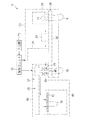
図8及び図9は、バー供給機構部40を示す概略平面図である。図10及び図11は、バー供給機構部40を示す概略側面図である。図8及び図10は、2つのバー支持部50のうち一方のバー支持部52が電線受取位置RPにある状態を示している。図9及び図11は、2つのバー支持部50のうち他方のバー支持部55が電線受取位置RPにある状態を示している。また、図12〜図14は、それぞれバー供給機構部40の一部を示す側面図、平面図及び正面図である。ここでは、バー供給機構部40は、端子付電線18の端部が保持された電線保持バー10を、空の電線保持バー10に入れ替えて円滑な処理が行われるように次の構成を採用している。
8 and 9 are schematic plan views showing the
即ち、バー供給機構部40は、それぞれ電線保持バー10を支持可能な2つのバー支持部50と、電線端部保持セット部からの電線受取位置RPと電線保持バー10の取出位置TPとの間で2つのバー支持部50をそれぞれ往復移動させる移動機構部60と、備えている。そして、2つのバー支持部50に対する取出位置TPが、電線保持バー10の延在方向に直交する方向に沿って、電線受取位置RPを挟んで異なっている。さらに、ここでは、2つのバー支持部50が一定の間隔を有した状態で往復移動可能となるように、2つのバー支持部50を同じ駆動源で一体的に移動させている。
That is, the bar
具体的には、ここでは、2つのバー支持部50が並列に並んだ状態(2つのバー支持部50に支持された電線保持バー10の延在方向が平行となる状態)でそれぞれの下方側で連結されている。そして、2つのバー支持部50は、移動機構部60により、電線保持バー10の延在方向に直交する方向に一体的に往復移動可能となっている。これにより、2つのバー支持部50に支持されたそれぞれの電線保持バー10の取出位置TPは、電線受取位置RPに対して逆の側方に設定されている。なお、これ以降、必要に応じて、2つのバー支持部50のうち一方を一方のバー支持部52、他方を他方のバー支持部55と呼称する。
Specifically, here, in the state where the two
一方のバー支持部52は、バー支持台53と、支柱部54とを有している。バー支持台53は、電線保持バー10のうち電線保持部14が設けられた部分とは反対側の一部を支持する。支柱部54は、鉛直方向に延びるように形成された棒状の部材で、一端側にバー支持部52が設けられている。
One
バー支持台53は梁部53aと、バー端部支持台53bと、バー端部支持部53cと、バー挟持部53dとを備える。
The
梁部53aは、支柱部54と連結されている棒状の部材である。ここでは、梁部53aの中間位置において、支柱部54の一端側と連結されている。梁部53aの上部にバー端部支持台53bと、バー端部支持部53cと、バー挟持部53dとが設けられている。
The
バー端部支持台53bとバー端部支持部53cとは、梁部53aの一方端部側に設けられ、電線保持バー10の一方端部側を支持可能に構成されている。具体的には、梁部53aの一方端部側の上面に板状のバー端部支持台53bが設けられ、バー端部支持台53bの一方側端部の周囲及びその上方を囲うようにバー端部支持部53cが立設されている。つまり、バー端部支持部53cは、平面視矩形に形成されている。これにより、電線保持バー10の延在方向において、電線保持バー10をバー端部支持部53cに向けて押すことで電線保持バー10の延在方向における位置決めをすることができる。
The bar end
バー挟持部53dは、電線保持バー10の中間位置を挟持するように電線保持バー10の延在方向に沿って、間隔をあけて2つ設けられている。バー挟持部53dは、バー支持台53に立設されている一対の挟持片を含む。一対の挟持片の間隔は、先端部側が基端部よりも広くなるように設定されている。また、基端部における一対の挟持片の間隔は、電線保持バー10の幅寸法と同程度に設定されている。なお、設けられるバー挟持部53dの数は、1つであってもよいし、3つ以上であってもよい。また、バー挟持部53dは、省略されてもよい。バー挟持部53dが設けられると、電線保持バー10の幅方向において、電線保持バー10が位置ずれしにくくなる。
Two
以上の構成により、電線保持バー10はバー支持台53に一方側端部及び中間位置を支持されている。そして、電線保持バー10の他方側端部は自由端になっている。このように、バー支持部52が電線保持バー10を片端支持することにより、バー支持部52から電線保持バー10を取り外す際に、電線保持バー10を水平方向にずらすだけで取り外すことができる。このため、電線保持バー10の取り外しが容易になるとともに、取り外しの際に端子付電線18の余長部分が引っ掛かる又は絡まることを抑えることができる。
With the above configuration, the electric
他方のバー支持部55は、上記と同様のバー支持台56と、支柱部57とを有し、支柱部57の一端側にバー支持台56が設けられている。そして、一方のバー支持部52の支柱部54と他方のバー支持部55の支柱部57とをそれぞれの他端側においてつなぐ連結部が設けられている。さらに、ここでは、一方のバー支持部52の支柱部54と他方のバー支持部55の支柱部57とは移動機構部60ともつながっている。
The other
また、ここでは、バー供給機構部40は、一対の床接地部41をさらに備える。移動機構部60は、一対の床接地部41の間の一部の区間において、2つのバー支持部50を往復移動させるように構成されている。移動機構部60は、エアシリンダ等のアクチュエータによって構成されている。
In addition, here, the bar
具体的には、移動機構部60は、ここでは、シリンダチューブ64と、シリンダチューブ64内を動くピストン65と、ピストン65に連結されているピストンロッド66とを有するエアシリンダ62によって構成されている。エアシリンダ62のシリンダチューブ64は、一方側の床接地部41に設けられている。そして、一方のバー支持部52の方が他方のバー支持部55よりもエアシリンダ62側に位置すると共に、エアシリンダ62のピストンロッド66が他方のバー支持部55と連結されている。これにより、移動機構部60は、他方のバー支持部55を直接的に動かすと共に、他方のバー支持部55とつながっている一方のバー支持部52を間接的に動かしている。
Specifically, here, the moving
もっとも、ピストンロッド66が、後述する移動柵58等のバー支持部50とつながる他の部材に連結されていてもよい。この場合でも、移動機構部60はバー支持部50を間接的に移動させることができる。つまり、移動機構部60は、バー支持部50を直接的又は間接的に移動可能であればよい。
But the
なお、ここでは、エアシリンダ62の軸方向とバー支持部50に支持された電線保持バー10の延在方向とが直交するように設定されている。これにより、2つのバー支持部50が電線保持バー10の延在方向と直交する方向に移動可能となっている。
Here, the axial direction of the
もっとも、2つのバー支持部50が電線保持バー10の延在方向と直交する方向に移動可能であることは必須ではなく、例えば、2つのバー支持部50が斜めに移動可能であってもよい。つまり、2つのバー支持部50の取出位置TPが電線受取位置RPを挟んで異なる位置にあり、2つのバー支持部50のすれ違いを抑えることができればよい。
However, it is not essential that the two
また、ここでは、バー供給機構部40は、一対の床接地部41間に平行に延びる一対のガイドレール68をさらに備える。一対のガイドレール68は、エアシリンダ62を挟むようにエアシリンダ62の両側方に1つずつ設けられている。つまり、エアシリンダ62が一対のガイドレール68の間に位置するように設けられている。そして、2つのバー支持部50はガイドレール68上を動くように構成されている。
Here, the bar
具体的には、バー支持部50の支柱部54,57の他端側には、一対のガイドレール68間の幅寸法と同程度の長さ寸法を持ち、ガイドレール68に沿って移動可能なレール走行部59が設けられている。
Specifically, the other end side of the
これにより、移動機構部60のエアシリンダ62で2つのバー支持部50が移動させられた際に、2つのバー支持部50が所定の軌道から外れることを抑えることができる。なお、ガイドレール68及びレール走行部59は、省略されてもよい。
Thereby, when the two
一方のバー支持部52に支持された電線保持バー10に対して端子付電線18の端部をセットする場合には、移動機構部60の駆動により一方のバー支持部52を電線受取位置RPに移動させる(図8及び図10の状態)。この際に、一方のバー支持部52の移動と同時に、他方のバー支持部55が取出位置TPに移動する。これにより、作業者は、他方のバー支持部55に対して、端子付電線18の端部をセット済の電線保持バー10を取外す、或は、空の電線保持バー10をセットすることができる。
When the end portion of the terminal-attached
そして、一方のバー支持部52に支持された電線保持バー10に対して端子付電線18の端部のセットが終了すると、移動機構部60の駆動により一方のバー支持部52を取出位置TPに移動させる(図9及び図11の状態)。この際に、一方のバー支持部52の移動と同時に、他方のバー支持部55が電線受取位置RPに移動する。これにより、他方のバー支持部55に支持された電線保持バー10に対して端子付電線18の端部がセットされている間に、一方のバー支持部52に支持された電線保持バー10の脱着を行うことができる。
When the setting of the end of the terminal-attached
上記のように、2つのバー支持部50を交互に電線受取位置RPと取出位置TPとに移動させることで、電線保持バー10に対する端子付電線18の端部のセットと電線保持バー10の脱着とを連続的に行うことができる。
As described above, by moving the two
もっとも、ここでは、1つの移動機構部60が2つのバー支持部50を一体的に動かしている例で説明したが、バー供給機構部40が2つの移動機構部60を備え、1つの移動機構部60が1つのバー支持部50を動かしていてもよい。つまり、2つのバー支持部50がそれぞれ独自に動くように構成されていてもよい。しかしながら、2つのバー支持部50を1つの移動機構部60で一体的に動かす構成にすることで、設備を簡略化することができる。
However, here, an example in which one moving
また、ここでは、バー供給機構部40は、ガイド部42をさらに備える。ガイド部42は、バー支持部50に支持された電線保持バー10が電線受取位置RPに位置する状態で水平となるように、バー支持部50の移動の際にバー支持部50に支持された電線保持バー10の延在方向他方側端部の高さを規制可能に設けられている。つまり、ガイド部42は自由端となっている電線保持バー10の他方側端部を支持することによって、電線受取位置RPにおいて、電線保持バー10の他方側端部を所定の高さに規制し、電線保持バー10が水平となるようにする部分である。
Here, the bar
具体的には、ガイド部42は、ここでは、等脚台形状の板状に形成されている。ガイド部42は、電線受取位置RPにおける電線保持バー10の延在方向に沿って、バー支持台53,56と間隔をあけるようにして設けられている。また、ガイド部42は、板の厚み方向が電線保持バーの延在方向と一致するように設けられている。ガイド部42の上面は、支持面43aと支持部から両側方に延びるガイド面43bとを有する。支持面43aは水平面と平行になるように設けられ、鉛直方向における支持面43aの高さは、バー端部支持台53bの上面の高さと等しくなるように設定されている。ガイド面43bは支持面43aから徐々に鉛直方向における高さが低くなるようにバー支持部50の移動方向に沿って延びている。
Specifically, the
取出位置TPにおいて、電線保持バー10の他方側端部は自由端となっており、電線保持バー10は水平状態もしくは他方側端部が若干下がる状態で支持されている。そして、電線保持バー10が、他方側端部が若干下がる状態に支持されている場合、取出位置TPから電線受取位置RPに向かう際に、その底面がガイド部42のガイド面43bと接触し、支持面43aまで導かれる。これにより、電線受取位置RPにおいて、電線保持バー10がガイド部42の支持面43aとバー端部支持台53bの上面とで水平状態で支持される。このため、電線保持バー10は、電線のセット中も水平に保たれる。なお、取出位置TPにおいて、電線保持バー10が、水平状態で支持されている場合は、電線保持バー10の他方側端部は、ガイド面43bと接触することなくそのまま支持面43aに支持される。
At the take-out position TP, the other end of the electric
また、ここでは、バー供給機構部40は、バー端部支持機構部44を備える。バー端部支持機構部44は、電線受取位置RPにある電線保持バー10の他方側端部を一方側端部に向けて押さえることが可能な部分である。
Here, the
具体的には、バー端部支持機構部44は、バー端部押部44aと、水平移動部44bとを備える。バー端部押部44aは、凹部44cが形成され、凹部44cに電線保持バー10の他方側端部の側面が嵌るように構成されている。
Specifically, the bar end
水平移動部44bは、エアシリンダ62等のアクチュエータによって構成されており、バー端部押部44aを水平方向に往復移動可能に構成されている。ここでは、水平移動部44bは、バー端部押部44aを電線保持バー10の延在方向に沿って移動可能に構成されている。
The horizontal moving
空の電線保持バー10が電線受取位置RPに来た状態で、水平移動部44bによりバー端部押部44aが電線保持バー10に接近する方向に移動し、電線保持バー10の他方側端部を一方側端部に向けて押え込む。これにより、電線保持バー10はその延在方向において所望の位置にセットされるとともに、電線を保持させる作業中に位置ずれを起こすことを抑えることができる。
With the empty
そして、電線保持バー10に所定の数の端子付電線をセットし終わると、水平移動部44bにより、バー端部押部44aが電線保持バー10から離れる方向に移動する。この際に、バー端部押部44aが電線保持バー10の移動領域内から外れるように移動する。これにより、電線のセットが完了した電線保持バー10が取出位置TPに向けて移動可能となるとともに、空の電線保持バー10が電線受取位置RPに向けて移動可能となる。以降、上記動作をバー支持部50の移動に伴い繰り返し行う。
When a predetermined number of terminal-attached electric wires are set in the electric
なお、バー支持部50が電線保持バー10の両端を支持する等によって、電線保持バー10を正しい位置に固定可能な場合、ガイド部42及びバー端部支持機構部44のどちらか一方或いは両方は省略されてもよい。
In addition, when the electric
また、ここでは、バー支持部50に支持された電線保持バー10の下方に位置する領域の少なくとも一部に絡み防止シート部46が設けられている。ここでは、電線保持バー10の下方とは、真下だけでなく斜め下の部分を含むものとする。
Here, the entanglement preventing
具体的には、ここでは、一方のバー支持部52に支持された電線保持バー10に端子付電線18をセットする場合、その余長部分は、図12のように、一方のバー支持部52と他方のバー支持部55との間に位置するようにセットする。このため、絡み防止シート部46は、一方のバー支持部52と他方のバー支持部55との間に設けられている。絡み防止シート部46は、電線保持バー10に保持された電線の余長部分が垂れ下がっている場合に、絡まってしまう、又は、他の部材に引っ掛かってしまう等を防ぐために設けられる。
Specifically, here, when the terminal-attached
より具体的には、絡み防止シート部46は、長方形状のシート状に形成されている。絡み防止シート部46の一方側縁部は一方のバー支持台53の側面に取り付けられ、他方側縁部は他方のバー支持台56の側面に取り付けられている。ここでは、粘着テープ等で貼り付けられることによって、絡み防止シート部46がバー支持部50に取り付けられている。また、絡み防止シート部46の長手方向の寸法は、バー支持部50間の寸法よりも大きく設定されており、その中間領域は一方のバー支持部52と他方のバー支持部55との間で垂れ下がっている。これにより、絡み防止シート部46は、ここでは、鉛直方向に沿う部分である鉛直部46aと水平方向に沿う部分である水平部46bとを含む。
More specifically, the entanglement preventing
鉛直部46aは、支柱部54,57にそれぞれ沿う部分であり、端子付電線18の余長部分が支柱部54,57等に引っ掛かること、又は、端子付電線18の余長部分がバー支持部50の移動時に揺れる等により互いに絡み合うことを抑える部分である。
The
水平部46bは、端子付電線18の余長部分が支柱部54,57よりも長い時に床に接触して擦れる等を抑える部分である。
The
もっとも、絡み防止シート部46が鉛直部46aと水平部46bとを含むことは必須ではない。
But it is not essential that the entanglement
例えば、絡み防止シート部46として、2つのシートを用意し、それぞれのシートの一方側縁部のみをそれぞれ別のバー支持台53,56に取り付け、2つのシートの他方側縁部は自由端とすることで、水平部46bを省略してもよい。しかしながら、2つのバー支持部50間をつなぐように絡みシート部46が設けられ、水平部46bを含むことにより、端子付電線18の余長部分が支柱部54,57よりも長い場合でも、余長部分を絡み防止シート部46上にとどめておくことができる。このため、端子付電線18の余長部分が床等と擦れることを抑えることができる。
For example, two sheets are prepared as the entanglement preventing
また、例えば、絡み防止シート部46として、バー支持部50間の寸法程度の長手方向の寸法を有する1枚のシートの両側縁部をそれぞれ別のバー支持部に取り付けることで、鉛直部46aを省略することができる。この場合、水平部46bは、端子付電線18の余長部分が支柱部54,57等に引っ掛かることを抑えるという鉛直部46aの一部の機能を兼ね備える。しかしながら、絡み防止シート部46の中間領域が垂れ下がるようにすることで、端子付電線18の余長部分も絡み防止シート部46の水平部46bまで垂れ下がることができる。このため、絡み防止シート部46上にとどまる端子付電線18の余長部分の量が少なくなることによって、端子付電線18の余長部分が互いに絡まりにくくなる。
Further, for example, as the entanglement preventing
さらに、ここでは、バー供給機構部40は、移動柵58をさらに備える。移動柵58は、2つのバー支持部50のうちの少なくとも一方に連結され、2つのバー支持部50と一体的に移動可能となっている。
Further, here, the bar
具体的には、移動柵58は、連結部58aと柵部58bとを備える。連結部58aは、他方のバー支持部55に連結され、他方のバー支持部55に対して、一方のバー支持部52が設けられている側とは反対側に設けられている。柵部58bは、連結部58aに立設され、2つのバー支持部50と並列に並ぶように設けられている。
Specifically, the moving
ここでは、他方のバー支持部55に支持された電線保持バー10に端子付電線18をセットする場合、端子付電線18の余長部分は、他方のバー支持部55と柵部58bとの間に位置するようにセットする。このため、絡み防止シート部46が他方のバー支持部55と柵部58bとの間にも設けられている。
Here, when the
他方のバー支持部55と柵部58bとの間においても、上記と同様に、長方形状のシートの一方側縁部がバー支持部50に取り付けられるとともに、他方側縁部が柵部58bに取り付けられることによって、絡み防止シート部46が設けられる。
Also between the other
これにより、他方のバー支持部55と柵部58bとの間においても、端子付電線18の引っ掛かり、絡まり又は擦れ等を押さえることができる。
Thereby, also between the other bar | burr support
もっとも、絡み防止シート部46は、省略されてもよい。なお、この場合、支柱部54,57及び柵部58bがそれぞれ壁状に形成されることで、絡み防止シート部46の替わりとすることができる。
But the tangle
なお、上記切圧機構部22及び電線排出装置30の動作は、CPU、ROMおよびRAM等を備える一般的なマイクロコンピュータによって構成された制御ユニット70によって制御される。制御ユニット70には各種キー等によって構成された入力部72が接続されており、当該入力部72を通じて作業指示が入力される。
The operations of the cutting
制御ユニット70は、当該入力部72を通じて切圧機構部22における複数種の端子付電線18の製造順に関する指令を受付け、当該指令に応じて複数種の電線や複数種の端子を選択して指令に応じた端子付電線18を製造するように制御する。本制御ユニット70は、当該入力部72を通じて製造された端子付電線18の端部の並び順に関する指令を受付け可能に構成されており、当該指令に応じて各端子付電線18の端部を電線保持バー10の各電線保持部14にセットしていくように構成されている。また、本制御ユニット70は、入力部72を通じて切圧機構部22で製造された端子付電線18のうちどの電線のどの端部を回転させるかの指令を受付け可能に構成されており、当該指令に応じて、上記各電線端部回転部33を制御して必要に応じた回転動作を行わせる。
The
また、制御ユニット70は、入力部72を通じてバー供給機構部40の移動機構部に関する指令を受け付け、当該指令に応じて一方のバー支持部52に支持された電線保持バー10が所定の数の端子付電線18を保持すると、他方のバー支持部55に支持された空の電線保持バー10と入れ替わるように制御する。また、本制御ユニット70は、入力部72を通じてバー端部支持機構部44に関する指令を受付け、当該指令に応じて水平移動部44bを電線受取位置RPに位置する電線保持バー10の端部への接近又は端部からの離隔動作を行わせる。
Further, the
<動作>
このように構成された切圧セット装置1及び電線排出装置30の全体動作について説明する。
<Operation>
The overall operation of the cutting
まず、切圧機構部22において所定の電線を所定長に切断して所定の端子を圧着した端子付電線18が順次製造される(図1参照)。すると、製造された端子付電線18の両端部が電線端部往復駆動部28の一対の各電線端部保持部27によって受渡し位置WPに搬送される。なお、同種の端子付電線18を連続して製造するか、或は、複数種類の端子付電線18を所定の順で製造するかは、予め上記入力部72を通じて制御ユニット70に与えられた指令に応じてなされる。
First, the
受渡し位置WPでは、端子付電線18の両端部が一対の電線端部回転部33にそれぞれ渡される。そして、必要に応じて、端子付電線18の各端部が一対の電線端部回転部33のそれぞれで回転される(図1、図3及び図4参照)。
At the delivery position WP, both end portions of the terminal-attached
一対の電線端部回転部33に把持された端子付電線18の両端部は、電線端部搬送セット部36の一対の把持部38でそれぞれ把持され、バー支持部50にセットされた電線保持バー10の上方に移動する。そして、電線保持バー10の長手方向に沿った適宜位置に移動した状態で、一対の把持部38が個別に下降移動することで、端子付電線18のそれぞれの端部が、電線保持バー10における所望位置の電線保持部14にセットされる(図1、図5〜図7参照)。
Both ends of the terminal-attached
切圧機構部22において順次製造された端子付電線18に対して上記処理を繰返すことで、電線保持バー10の各電線保持部14には、複数の端子付電線18の両端部がセットされる。これにより、複数の端子付電線18の両端部が電線保持バー10の各電線保持部14にセットされたものが得られる。
By repeating the above process on the terminal-attached
一方のバー支持部52に支持された電線保持バー10への端子付電線18のセットが完了すると、制御ユニット70が指令を与える。この指令に応じて移動機構部60により、他方のバー支持部55に支持された空の電線保持バー10を電線受取位置RPに移動させるとともに、一方のバー支持部52に支持されたセット済みの電線保持バー10を取出位置TPに移動させる。そして、他方のバー支持部55に支持された電線保持バー10に端子付電線18がセットされている間に、作業者は、一方のバー支持部52に支持されたセット済みの電線保持バー10を取り外すとともに、一方のバー支持部52に空の電線保持バー10を取り付ける(図8〜図14参照)。
When the setting of the
このように、作業者が取出位置TPにおいて、セット済みの電線保持バー10を空のものに交換する作業を繰返すことで、端子付電線18の端部がセットされた複数セットの電線保持バー10を得ることができる。
As described above, when the operator repeats the work of replacing the set electric
<効果>
以上のように構成された電線排出装置30によると、切断及び端子圧着された端子付電線18の端部が、電線保持バー10の各電線保持部14に並列状にセットしたものを得ることができる。このため、下流工程での作業利便性を向上させることができると共に、電線や端子への傷付き、破損等を防止することができる。
<Effect>
According to the electric
また、複数種類の端子付電線18の端部が、電線保持バー10の複数の電線保持部14に予め設定された順で並んだものを得ることができる。このため、例えば、当該順を下流工程における作業順に応じた順とすることができ、下流工程での作業利便性をより向上させることができる。
In addition, it is possible to obtain a plurality of types of terminal-attached
また、同一種類の端子付電線18を製造する場合においても、当該同一種類の端子付電線18の端部が電線保持バー10の複数の電線保持部14に並列状に並んだものを得ることができる。このため、同一種類の端子付電線18を製造する場合に関しても、下流工程での作業利便性を向上させることができる。
In addition, even when the same type of
また、端子付電線18の端部を電線端部回転部33で回転させているため、端子付電線18の端部を、下流工程での処理に適した姿勢で回転させた状態で、電線保持部14にセットすることができる。このため、下流工程での作業利便性により優れる。
Moreover, since the end part of the
また、2つのバー支持部50に支持された電線保持バー10の取出位置TPが電線保持バー10の延在方向に直交する方向に沿って、電線受取位置RPを挟んで異なっているため、各電線保持バー10が電線受取位置RPと取出位置TPとの間で往復移動する際にすれ違いにくくなることによって、電線が絡まる又は引っ掛かることを抑えることができる。
Further, since the take-out position TP of the electric
また、2つのバー支持部50を同じ駆動源で動かしているため、2つのバー支持部50が常に一定の間隔を有した状態で往復移動可能となることによって、2つのバー支持部50がすれ違うことがなくなり、電線が絡まる又は引っ掛かることを抑えることができる。また、2つのバー支持部を別の駆動源で動かす場合に比べて、設備構造を簡素化することができる。
Further, since the two
また、バー支持部50のうち電線保持バー10の下方に位置する部分に絡み防止シート部46が設けられているため、電線保持バー10に保持された電線が電線保持バー10の下方で絡まる又は引っ掛かることを抑えることができる。
Moreover, since the entanglement
また、バー支持部50は電線保持バー10の延在方向一方側端部を支持するとともに、バー支持部50の移動の際にバー支持部50に支持された電線保持バー10の延在方向他方側端部の高さを規制可能なガイド部42をさらに備えるため、バー支持部50に支持された電線保持バー10が電線受取位置RPに位置する状態で水平となるように規制される。これにより、電線保持バー10が正しい位置にセットされていない状態で電線をセットする作業を始めることを抑えることができる。また、電線保持バー10が片端支持されているため、電線保持バー10を取り外しやすくなるとともに、取り外しの際に電線の引っ掛かり又は絡まり等を抑えることができる。
Further, the
また、バー支持部50に支持された電線保持バー10が電線受取位置RPに位置する状態で、電線保持バー10の延在方向他方側端部を一方側端部に向けて押さえつけることができるバー端部支持機構部44をさらに備えるため、電線保持バー10が正しい位置にセットされていない状態で電線をセットする作業を始めることを抑えることができる。
In addition, in the state where the electric
なお、本実施形態では、端子付電線18の両方の端部を電線保持バー10にセットする例で説明したが、一方の端部だけを電線保持バー10にセットする構成であってもよい。この場合、端子付電線18の他方の端部については、コネクタハウジングに挿入してしまってもよいし、或は、束ねた状態としてもよい。また、切圧機構部22から搬送される端子付電線18の両端部に端子が圧着されている必要はなく、例えば、一端だけに端子が圧着された電線等が存在していてもよい。
In addition, although this embodiment demonstrated the example which sets both the edge parts of the
また、切圧機構部22で端子圧着された直後の端子付電線18の端部を把持する機構部を、電線排出装置30側の構成として備えていてもよい。
Moreover, you may provide the mechanism part which hold | grips the edge part of the
以上のようにこの発明は詳細に説明されたが、上記した説明は、すべての局面において、例示であって、この発明がそれに限定されるものではない。例示されていない無数の変形例が、この発明の範囲から外れることなく想定され得るものと解される。 As described above, the present invention has been described in detail. However, the above description is illustrative in all aspects, and the present invention is not limited thereto. It is understood that countless variations that are not illustrated can be envisaged without departing from the scope of the present invention.
10 電線保持バー
14 電線保持部
18 端子付電線
22 切圧機構部
30 電線排出装置
32 電線端部保持セット部
33 電線端部回転部
36 電線端部搬送セット部
40 バー供給機構部
42 ガイド部
44 バー端部支持機構部
46 絡み防止シート部
50,52,55 バー支持部
60 移動機構部
70 制御ユニット
RP 電線受取位置
TP 取出位置
DESCRIPTION OF
Claims (5)
前記バー支持部に支持された前記電線保持バーの前記複数の電線保持部に電線を順次セットする電線端部保持セット部と、
前記電線端部保持セット部からの電線受取位置と前記電線保持バーの取出位置との間で2つの前記バー支持部をそれぞれ往復移動させる移動機構部と、
を備え、
2つの前記バー支持部に対する前記取出位置が、前記電線保持バーの延在方向に直交する方向に沿って、前記電線受取位置を挟んで異なっている、電線排出装置。 Two bar support portions capable of supporting an electric wire holding bar provided with a plurality of electric wire holding portions in parallel;
An electric wire end holding set portion for sequentially setting electric wires in the plurality of electric wire holding portions of the electric wire holding bar supported by the bar supporting portion;
A moving mechanism for reciprocally moving the two bar support portions between the wire receiving position from the wire end holding set portion and the wire holding bar take-out position;
With
The wire discharge device, wherein the take-out positions with respect to the two bar support portions are different across the wire receiving position along a direction orthogonal to the extending direction of the wire holding bar.
前記移動機構部は、2つの前記バー支持部が一定の間隔を有した状態で往復移動可能となるように、2つの前記バー支持部を同じ駆動源で一体的に移動させる、電線排出装置。 The wire discharge device according to claim 1,
The electric wire discharging device, wherein the moving mechanism unit integrally moves the two bar support portions with the same drive source so that the two bar support portions can be reciprocated with a constant interval.
前記バー支持部に支持された前記電線保持バーの下方に位置する部分に絡み防止シート部が設けられている、電線排出装置。 The wire discharge device according to claim 1 or 2,
An electric wire discharging device in which a entanglement preventing sheet portion is provided at a portion located below the electric wire holding bar supported by the bar supporting portion.
前記バー支持部は前記電線保持バーの延在方向における一方側端部を支持し、
前記バー支持部に支持された前記電線保持バーが前記電線受取位置に位置する状態で水平となるように、前記バー支持部の移動の際に前記バー支持部に支持された前記電線保持バーの延在方向における他方側端部の高さを規制可能なガイド部をさらに備える、電線排出装置。 The wire discharge device according to any one of claims 1 to 3,
The bar support portion supports one end portion in the extending direction of the electric wire holding bar,
The wire holding bar supported by the bar support portion during the movement of the bar support portion so that the wire holding bar supported by the bar support portion is horizontal in a state of being positioned at the wire receiving position. An electric wire discharging apparatus further comprising a guide portion capable of regulating the height of the other end portion in the extending direction.
前記バー支持部に支持された前記電線保持バーが前記電線受取位置に位置する状態で、前記電線保持バーの延在方向における前記他方側端部を前記一方側端部に向けて押さえつけることができるバー端部支持機構部をさらに備える、電線排出装置。 The wire discharge device according to claim 4,
With the wire holding bar supported by the bar support portion positioned at the wire receiving position, the other end in the extending direction of the wire holding bar can be pressed toward the one end. An electric wire discharging device further comprising a bar end portion supporting mechanism.
Priority Applications (7)
| Application Number | Priority Date | Filing Date | Title |
|---|---|---|---|
| JP2013261221A JP6107639B2 (en) | 2013-12-18 | 2013-12-18 | Electric wire discharge device |
| US15/100,485 US20160301178A1 (en) | 2013-12-18 | 2014-12-03 | Wire discharge device |
| EP14872453.7A EP3086329A4 (en) | 2013-12-18 | 2014-12-03 | Wire ejection device |
| KR1020167015482A KR20160085852A (en) | 2013-12-18 | 2014-12-03 | Wire ejection device |
| PCT/JP2014/081978 WO2015093292A1 (en) | 2013-12-18 | 2014-12-03 | Wire ejection device |
| CN201480070029.5A CN105849824A (en) | 2013-12-18 | 2014-12-03 | Wire ejection device |
| TW103142374A TWI559337B (en) | 2013-12-18 | 2014-12-05 | Wire discharge device |
Applications Claiming Priority (1)
| Application Number | Priority Date | Filing Date | Title |
|---|---|---|---|
| JP2013261221A JP6107639B2 (en) | 2013-12-18 | 2013-12-18 | Electric wire discharge device |
Publications (2)
| Publication Number | Publication Date |
|---|---|
| JP2015118793A JP2015118793A (en) | 2015-06-25 |
| JP6107639B2 true JP6107639B2 (en) | 2017-04-05 |
Family
ID=53402641
Family Applications (1)
| Application Number | Title | Priority Date | Filing Date |
|---|---|---|---|
| JP2013261221A Active JP6107639B2 (en) | 2013-12-18 | 2013-12-18 | Electric wire discharge device |
Country Status (7)
| Country | Link |
|---|---|
| US (1) | US20160301178A1 (en) |
| EP (1) | EP3086329A4 (en) |
| JP (1) | JP6107639B2 (en) |
| KR (1) | KR20160085852A (en) |
| CN (1) | CN105849824A (en) |
| TW (1) | TWI559337B (en) |
| WO (1) | WO2015093292A1 (en) |
Families Citing this family (4)
| Publication number | Priority date | Publication date | Assignee | Title |
|---|---|---|---|---|
| JP2017117609A (en) * | 2015-12-24 | 2017-06-29 | 住友電装株式会社 | Wire ejection device |
| CN107492425B (en) * | 2017-08-13 | 2019-04-19 | 新昌县管富机械有限公司 | A kind of waste and old cable peeling recyclable device |
| CN109449721B (en) * | 2018-11-05 | 2019-11-05 | 大庆市华禹石油机械制造有限公司 | A kind of servomotor conducting wire arrangement apparatus |
| KR102105268B1 (en) * | 2019-09-20 | 2020-04-27 | 이준열 | Cable label attaching device |
Family Cites Families (18)
| Publication number | Priority date | Publication date | Assignee | Title |
|---|---|---|---|---|
| US5412933A (en) * | 1992-09-17 | 1995-05-09 | Joel D. Mallett | Automatic link forming apparatus |
| JP3632937B2 (en) | 1996-05-20 | 2005-03-30 | 矢崎総業株式会社 | Harness manufacturing method, pressure welding machine, connector holding rod and pressure welding device |
| JP3892919B2 (en) * | 1996-10-03 | 2007-03-14 | 矢崎総業株式会社 | Wire harness manufacturing method and manufacturing apparatus |
| JP4327335B2 (en) * | 2000-06-23 | 2009-09-09 | 株式会社アドバンテスト | Contact arm and electronic component testing apparatus using the same |
| US6961996B2 (en) * | 2001-04-10 | 2005-11-08 | Komax Holding Ag | Method for installing cable ends in plug housings |
| DE50214847D1 (en) * | 2001-10-31 | 2011-02-17 | Komax Holding Ag | Handling device for wire line, insertion machine and insertion method with such a handling device |
| JP4063127B2 (en) * | 2003-04-10 | 2008-03-19 | 住友電装株式会社 | Automatic production system for wire harness |
| JP3982480B2 (en) | 2003-10-31 | 2007-09-26 | 住友電装株式会社 | Multi-crimping device and terminal supply module |
| DE502004007792D1 (en) * | 2004-11-02 | 2008-09-18 | Komax Holding Ag | cable storage |
| JP5194772B2 (en) * | 2007-12-21 | 2013-05-08 | 住友電装株式会社 | Cutting pressure setting device and method of manufacturing wire harness |
| JP2009152105A (en) * | 2007-12-21 | 2009-07-09 | Sumitomo Wiring Syst Ltd | Wire set aligning apparatus, and manufacturing method of sub-assembly |
| JP5287108B2 (en) * | 2008-10-01 | 2013-09-11 | 住友電装株式会社 | Electric wire connection assembly manufacturing support device and electric wire connection assembly manufacturing method |
| US8113557B2 (en) * | 2009-05-19 | 2012-02-14 | Artos Engineering Company | Wire gripper jaw drive |
| JP4985713B2 (en) * | 2009-06-10 | 2012-07-25 | 住友電装株式会社 | Electric wire holding bar conveying device and electric wire set manufacturing method |
| CN103415898B (en) * | 2011-03-08 | 2015-09-30 | 日本自动机械株式会社 | The manufacturing installation of wire harness and manufacture method |
| JP5842631B2 (en) * | 2012-01-25 | 2016-01-13 | 住友電装株式会社 | Electric wire holding bar conveyor |
| JP5817576B2 (en) * | 2012-02-09 | 2015-11-18 | 住友電装株式会社 | Wire transfer device |
| CN202805184U (en) * | 2012-09-06 | 2013-03-20 | 东莞市五株电子科技有限公司 | Manipulator picking and placing equipment |
-
2013
- 2013-12-18 JP JP2013261221A patent/JP6107639B2/en active Active
-
2014
- 2014-12-03 CN CN201480070029.5A patent/CN105849824A/en active Pending
- 2014-12-03 KR KR1020167015482A patent/KR20160085852A/en active IP Right Grant
- 2014-12-03 US US15/100,485 patent/US20160301178A1/en not_active Abandoned
- 2014-12-03 EP EP14872453.7A patent/EP3086329A4/en not_active Withdrawn
- 2014-12-03 WO PCT/JP2014/081978 patent/WO2015093292A1/en active Application Filing
- 2014-12-05 TW TW103142374A patent/TWI559337B/en not_active IP Right Cessation
Also Published As
| Publication number | Publication date |
|---|---|
| TW201535422A (en) | 2015-09-16 |
| CN105849824A (en) | 2016-08-10 |
| EP3086329A1 (en) | 2016-10-26 |
| WO2015093292A1 (en) | 2015-06-25 |
| TWI559337B (en) | 2016-11-21 |
| JP2015118793A (en) | 2015-06-25 |
| EP3086329A4 (en) | 2017-01-04 |
| US20160301178A1 (en) | 2016-10-13 |
| KR20160085852A (en) | 2016-07-18 |
Similar Documents
| Publication | Publication Date | Title |
|---|---|---|
| JP5194772B2 (en) | Cutting pressure setting device and method of manufacturing wire harness | |
| JP6107639B2 (en) | Electric wire discharge device | |
| US11324124B2 (en) | Lead component clinching and mounting method | |
| KR20180098295A (en) | Pincers | |
| JP4985713B2 (en) | Electric wire holding bar conveying device and electric wire set manufacturing method | |
| WO2009081605A1 (en) | Electrical wire set aligning apparatus and method for manufacturing sub-assembly | |
| JP2008271632A (en) | Wire stripper, wire harness pressure-welding machine and wire stripping method | |
| BR112013033408B1 (en) | method and device for continuous production of a truss support | |
| JP5317106B2 (en) | Coil forming apparatus and coil forming method | |
| CN105405640A (en) | Thick wire winding machine | |
| WO2018012337A1 (en) | Wire harness production device and wire harness production method | |
| CN111362051A (en) | Cable transfer device of intelligent wire harness machine | |
| JP2010277904A (en) | Manufacturing method of wire harness and cart for electric wire transfer and wiring | |
| JP6003877B2 (en) | Terminal feeder | |
| JP6457804B2 (en) | Terminal crimping jig set auxiliary device and terminal crimping system | |
| KR101431784B1 (en) | Unit for anti-loose tape and Winder machine of the carrier having it | |
| WO2013125068A1 (en) | Apparatus for exchanging terminal forming die device | |
| WO2017110489A1 (en) | Wire delivery device | |
| JP5548802B2 (en) | Coil forming equipment | |
| JP4649449B2 (en) | Wire length measuring device for wire processing machine | |
| JP2003223822A (en) | Manufacturing equipment for wire harness | |
| JP5768749B2 (en) | Electric wire processing equipment | |
| JP2007238147A (en) | Winding and storing method and device for flexible workpiece | |
| JP2004314124A (en) | Folding mechanism for wire netting | |
| JP2003142223A (en) | Terminal belt cutting device and terminal mounting device using the same |
Legal Events
| Date | Code | Title | Description |
|---|---|---|---|
| A621 | Written request for application examination |
Free format text: JAPANESE INTERMEDIATE CODE: A621 Effective date: 20160127 |
|
| A131 | Notification of reasons for refusal |
Free format text: JAPANESE INTERMEDIATE CODE: A131 Effective date: 20170117 |
|
| A521 | Written amendment |
Free format text: JAPANESE INTERMEDIATE CODE: A523 Effective date: 20170124 |
|
| TRDD | Decision of grant or rejection written | ||
| A01 | Written decision to grant a patent or to grant a registration (utility model) |
Free format text: JAPANESE INTERMEDIATE CODE: A01 Effective date: 20170207 |
|
| A61 | First payment of annual fees (during grant procedure) |
Free format text: JAPANESE INTERMEDIATE CODE: A61 Effective date: 20170220 |
|
| R150 | Certificate of patent or registration of utility model |
Ref document number: 6107639 Country of ref document: JP Free format text: JAPANESE INTERMEDIATE CODE: R150 |