EP2813813A1 - Inside-diameter measurement device - Google Patents
Inside-diameter measurement device Download PDFInfo
- Publication number
- EP2813813A1 EP2813813A1 EP13747245.2A EP13747245A EP2813813A1 EP 2813813 A1 EP2813813 A1 EP 2813813A1 EP 13747245 A EP13747245 A EP 13747245A EP 2813813 A1 EP2813813 A1 EP 2813813A1
- Authority
- EP
- European Patent Office
- Prior art keywords
- unit
- contact
- measuring unit
- advancing
- contact measuring
- Prior art date
- Legal status (The legal status is an assumption and is not a legal conclusion. Google has not performed a legal analysis and makes no representation as to the accuracy of the status listed.)
- Granted
Links
Images


Classifications
-
- G—PHYSICS
- G01—MEASURING; TESTING
- G01B—MEASURING LENGTH, THICKNESS OR SIMILAR LINEAR DIMENSIONS; MEASURING ANGLES; MEASURING AREAS; MEASURING IRREGULARITIES OF SURFACES OR CONTOURS
- G01B11/00—Measuring arrangements characterised by the use of optical techniques
- G01B11/08—Measuring arrangements characterised by the use of optical techniques for measuring diameters
- G01B11/12—Measuring arrangements characterised by the use of optical techniques for measuring diameters internal diameters
-
- G—PHYSICS
- G01—MEASURING; TESTING
- G01B—MEASURING LENGTH, THICKNESS OR SIMILAR LINEAR DIMENSIONS; MEASURING ANGLES; MEASURING AREAS; MEASURING IRREGULARITIES OF SURFACES OR CONTOURS
- G01B11/00—Measuring arrangements characterised by the use of optical techniques
- G01B11/24—Measuring arrangements characterised by the use of optical techniques for measuring contours or curvatures
-
- G—PHYSICS
- G01—MEASURING; TESTING
- G01B—MEASURING LENGTH, THICKNESS OR SIMILAR LINEAR DIMENSIONS; MEASURING ANGLES; MEASURING AREAS; MEASURING IRREGULARITIES OF SURFACES OR CONTOURS
- G01B11/00—Measuring arrangements characterised by the use of optical techniques
- G01B11/24—Measuring arrangements characterised by the use of optical techniques for measuring contours or curvatures
- G01B11/25—Measuring arrangements characterised by the use of optical techniques for measuring contours or curvatures by projecting a pattern, e.g. one or more lines, moiré fringes on the object
-
- G—PHYSICS
- G01—MEASURING; TESTING
- G01B—MEASURING LENGTH, THICKNESS OR SIMILAR LINEAR DIMENSIONS; MEASURING ANGLES; MEASURING AREAS; MEASURING IRREGULARITIES OF SURFACES OR CONTOURS
- G01B5/00—Measuring arrangements characterised by the use of mechanical techniques
- G01B5/08—Measuring arrangements characterised by the use of mechanical techniques for measuring diameters
- G01B5/12—Measuring arrangements characterised by the use of mechanical techniques for measuring diameters internal diameters
-
- G—PHYSICS
- G02—OPTICS
- G02B—OPTICAL ELEMENTS, SYSTEMS OR APPARATUS
- G02B23/00—Telescopes, e.g. binoculars; Periscopes; Instruments for viewing the inside of hollow bodies; Viewfinders; Optical aiming or sighting devices
- G02B23/24—Instruments or systems for viewing the inside of hollow bodies, e.g. fibrescopes
Definitions
- the present invention relates to an inner diameter measuring device for measuring an inner diameter of a hollow member.
- a non-contact type inner diameter measuring device which projects a laser beam over total circumference, forms an optical ring on inner surface, takes an image of an optical ring thus formed, and measures inner diameter, shape, and profile of the hollow member on the image.
- an inner diameter measuring device which brings contact to inner surface of the hollow member with a contact, and measures the inner diameter.
- the devices disclosed in the Patent Document 1 and the Patent Document 2 are known. According to each of the Patent Document 1 and the Patent Document 2 discloses a non-contact type inner diameter measuring device, a laser beam is projected over total circumference, an optical ring formed on inner surface of a cylindrical object is photographed and shape and diameter of the optical ring is measured on the image.
- a device disclosed in the Patent Document 3 is known.
- a pipe to be inspected is rotatably supported by a pipe rotation supporting device, and the device comprises a running carriage device where a pair of upper and lower inner diameter measuring sensors are provided in closely separable manner.
- the inner diameter measurement sensor is inserted into the inside of the pipe to be inspected.
- the sensor is brought into contact with inner surface of the pipe to be inspected.
- the pipe to be inspected is rotated by the pipe rotation supporting device, and inner diameter of the pipe to be inspected is measured.
- the non-contact type inner diameter measuring device in the former case, a shape and a condition of the inner surface can be quickly identified, and it is advantageous in that the measurement can be carried out within shorter time, and the conditions of inner surface such as graded step, taper, etc. at one time, and entire shape and condition can be identified, while there is a problem that the measurement with high accuracy cannot perform.
- the contact type inner diameter measuring device in the latter case, the measurement results with high accuracy can be obtained, while measurement must be performed one by one and much time is required. Further, measurement must be performed at a multiple of points for measuring a shape of inner surface, and a long time is required for the measurement. Also, there are problems in that it is difficult to identify the conditions of inner surface such as graded step, taper, etc.
- an object of the present invention to provide an inner diameter measuring device, by which it is possible to quickly identify the conditions of the inner surface and entire shape, and moreover, to obtain the measurement results with higher accuracy.
- the present invention relates to an inner diameter measuring device, having a non-contact measuring unit and a contact measuring unit arranged along the same center line, wherein the non-contact measuring unit comprises an image pickup unit arranged on the center line, a laser beam emitting unit, and a laser beam diffusing unit having a cone mirror, wherein a laser beam projected from the laser beam emitting unit to the cone mirror is reflected over a total circumference by the cone mirror, the image pickup unit takes an optical ring which is formed by projecting the reflected laser beam to an inner surface of a hollow portion, at least one of an inner diameter or a shape of the inner surface is measured based on an image picked up, and wherein the contact measuring unit comprises a contact measuring head and a circulation unit for circulating the contact measuring head around the center line, wherein the contact measuring head has a contact measuring unit having a contact at a forward end and for detecting a displacement of the contact, an advancing/retreating unit for advancing and retreating the contact measuring unit in radial direction, and a scale unit
- the present invention relates to an inner diameter measuring device, wherein the non-contact measuring unit and the contact measuring unit are configured so as to be included within the same cylindrical surface.
- the present invention relates to an inner diameter measuring device, further comprising a centering unit arranged on the same center line, wherein the laser beam emitting unit is mounted on the centering unit via the centering unit, the position of the centering unit can be adjusted in two directions perpendicularly crossing with respect to the center line of the laser beam, and also, a tilting of an optical axis of the laser beam emitting unit can be adjusted.
- the present invention relates to an inner diameter measuring device, wherein the contact measuring head is so arranged that a center of gravity of the contact measuring head exists within a predetermined range with the center line as the center.
- the present invention relates to an inner diameter measuring device, wherein the contact measuring unit is provided on a measuring unit holder movable in radial direction along an advancing/retreating guide rail, a linear scale is provided in parallel to the advancing/retreating guide rail, a scale sensor is provided on the measuring unit holder, and the advancing/retreating distance of the contact measuring unit is measured by the scale sensor.
- the present invention relates to an inner diameter measuring device, wherein the contact measuring head has a measuring unit supporting base plate circulated by the circulation unit, the advancing/retreating unit is provided on the measuring unit supporting base plate via two sets of linear guides, each linear guide comprises a pair of advancing/retreating guide rails and a pair of blocks respectively slidably engaged with the advancing/retreating guide rail, wherein with respect to one of the linear guides, the advancing/retreating guide rail is provided on the measuring unit supporting base plate and the block is provided on the advancing/retreating unit, and with respect to the other of the linear guides, the advancing/retreating guide rail is provided on the advancing/retreating unit and the block is provided on the measuring unit supporting base plate.
- FIG. 1 shows an embodiment according to the present invention.
- reference numeral 1 denotes an inner diameter measuring device
- reference numeral 2 denotes a rod-like supporting member for supporting the inner diameter measuring device 1.
- the inner diameter measuring device 1 is designed in a shape, which can be included in a cylindrical surface.
- the cylindrical surface can also include the supporting member 2 and the cylindrical surface is designed to be shorter than the inner diameter of a hollow portion of an object to be measured.
- the inner diameter measuring device 1 comprises a non-contact measuring unit 3 and a contact measuring unit 4.
- the non-contact measuring unit 3 and the contact measuring unit 4 are arranged along an extension of a center line of the supporting member 2. Further, the non-contact measuring unit 3 and the contact measuring unit 4 are arranged in such manner that the contact measuring unit 4 can be connected or disconnected from each other.
- the non-contact measuring unit 3 primarily comprises an image pickup unit 6, a laser beam emitting unit 7, a centering unit 8, a laser beam diffusing unit 9, a frame unit 11, etc. Also, an optical axis of the image pickup unit 6, an optical axis of the laser beam emitting unit 7, a center line of the centering unit 8, a center line of the laser beam diffusing unit 9, and a center line of the frame unit 11 coincide with the center line of the supporting member 2.
- the frame unit 11 is constituted in such a manner that a base end ring 12 and a forward end ring 13 are connected with each other by a plurality of supporting pillars 14.
- the supporting pillars 14 are arranged on the same circumference at positions with predetermined distance, e.g. at three equally distanced positions.
- a space penetrating from the base end to the forward end is formed.
- the image pickup unit 6 is mounted on the base end ring 12.
- the image pickup unit 6 has a camera holder 15 to be mounted on the base end ring 12 and a camera 16 to be accommodated in the camera holder 15.
- the camera holder 15 is connected to the supporting member 2.
- An optical axis of the camera 16 coincides with the center line of the supporting member 2 and the center line of the frame unit 11.
- the camera 16 has a CCD or a CMOS sensor, etc., which is an aggregate of pixels, as an image pickup element.
- the image pickup element outputs digital image signals, which are an aggregate of signals from each pixel, and it is so arranged that signals from each pixel can identify positions respectively within the image pickup element.
- the centering unit 8 is fixed on the forward end ring 13, and the laser beam diffusing unit 9 is fixed on a forward end of the centering unit 8.
- An axis adjusting mechanism 18 is accommodated in the centering unit 8, and the laser beam emitting unit 7 is mounted on a base end side of the axis adjusting mechanism 18.
- the laser beam emitting unit 7 has a light emitter holder 19 of pipe-like shape to be fixed on the axis adjusting mechanism 18, and a laser emitter 20 fitted into and attached to the base end portion of the light emitter holder 19, and an optical axis of the laser beam 21 emitted from the laser emitter 20 coincides with optical axis of the camera 16 and with the center line of the frame unit 11.
- the axis adjusting mechanism 18 has an X-axis slider 25, which perpendicularly crosses the laser beam 21 and slides in a direction perpendicular to paper surface, and also, has a Y-axis slider 26, which is provided on the X-axis slider 25 and slides in a direction in parallel to the paper surface. It is so arranged that positions of the X-axis slider 25 and the Y-axis slider 26 can be adjusted by adjusting screws (not shown) respectively.
- the light emitter holder 19 is mounted on the Y-axis slider 26. Further, the light emitter holder 19 is fixed at three equally divided positions on circumference by fixing means 27 having a pair of pushing screw and pulling screw. By adjusting the fixing means 27, tilting of the center line of the light emitter holder 19, i.e. tilting of optical axis of the laser beam 21 can be adjusted.
- a position of an optical axis of the laser beam 21 can be adjusted in two directions perpendicularly crossing each other, i.e. in X-axis direction and in Y-axis direction, and a tilting of the optical axis can be adjusted by the fixing means 27, and also, that optical axis of the laser beam 21 can coincide with a center line of the image pickup unit 6 and a center line of a cone mirror 29 (to be described later).
- a laser beam diffusing unit 9 is provided, and the laser beam diffusing unit 9 has a cone mirror 29 on the center line and a total circumferential light transmitting window 30, which is concentric to the cone mirror 29.
- the cone mirror 29 has a conical curved surface with an end pointed toward the laser emitter 20, and vertical angle of the curved surface is set to 90°, for instance.
- the cone mirror 29 can be changed as appropriate to the one having different vertical angle, depending on the measurement circumstance, e.g. with vertical angle of 120° or 60°.
- the laser beam 21 is projected from the laser emitter 20
- the laser beam 21 enters vertex of the cone mirror 29 and is reflected in total circumferential direction by conical curved surface.
- a reflected laser beam 21' which passed through the total circumferential light transmitting window 30 is projected to inner surface of hollow portion, an optical ring is formed. The optical ring is picked up by the camera 16.
- the supporting pillars 14 there may be two or four supporting pillars 14. There is no problem in so far as the supporting pillars 14 can support the image pickup unit 6, the centering unit 8, and the laser beam diffusing unit 9, and no trouble is caused in the image pickup of the image pickup unit 6.
- a measuring unit main part (not shown) has an image processing unit.
- the image processing unit processes the image picked up by the camera 16, and measures an inner diameter and a shape (true circle, ellipse, etc.), or at least one of the inner diameter and the shape. Further, under the condition that the reflected laser beam 21' is projected, when the inner diameter measuring device 1 is moved in axial direction, and images are acquired, an information such as condition of inner surface, e.g. taper, graded step, etc., can be acquired.
- reference numeral 41 denotes a circulation unit
- reference numeral 42 denotes a contact measuring head
- reference numeral 43 denotes a center line of the contact measuring unit 4.
- a center line of the circulation unit 41 coincides with a center line of the supporting member 2 and with a center line of the non-contact measuring unit 3. Further, a connection adapter 44 is provided at a base end, and the circulation unit 41 is connected to the non-contact measuring unit 3 via the connection adapter 44 or the circulation unit 41 is connected with the supporting member 2.
- a shaft holder 45 which is hollow, is mounted on the connection adapter 44.
- a center line of the shaft holder 45 coincides with the center line 43, and a circulation shaft 48 is rotatably supported around the center line 43 via bearings 46 and 47.
- the circulation shaft 48 is designed as hollow.
- a circulation flange 49 is formed at a forward end (on the left side in FIG.3 ) of the circulation shaft 48. Further, on base side of the circulation flange 49, a circulation gear 51 is engaged with the circulation shaft 48.
- a circulation motor 52 is provided.
- a circulation driving gear 53 is fitted and fixed on an output shaft of the circulation motor 52, and the circulation driving gear 53 is engaged with the circulation gear 51.
- the circulation motor 52 has an encoder (not shown), and the amount of rotation of the circulation driving gear 53, i.e. the amount of rotation of the circulation gear 51, can be detected.
- a circulation restricting means 54 of the circulation flange 49 is provided.
- a limit switch 55 is provided on the shaft holder 45, and a switch operating piece 56 to operate the limit switch 55 is attached on the circulation flange 49.
- a proximity switch is used as the limit switch 55, and a metal piece, which is set so as to face each other the limit switch 55 at an interval as required, is used as the switch operating piece 56.
- a circulation unit cover 58 in cylindrical shape to cover the connection adapter 44, the shaft holder 45, the circulation flange 49, the circulation motor 52 and the circulation restricting means 54 is provided to stretch over from the base end of the connection adapter 44 to the circulation flange 49.
- the circulation unit cover 58 is not contacted with the circulation flange 49.
- the contact measuring head 42 has a circulation base plate 61 at base end, and since the circulation base plate 61 is fixed on the circulation flange 49, the circulation unit 41 and the contact measuring head 42 are connected with each other and it is so comprised that the circulation unit 41 and the contact measuring head 42 are integrated with each other.
- the contact measuring head 42 is concentric with the circulation unit 41, i.e. the contact measuring head 42 is concentric with the laser beam emitting unit 7. That is, the circulation unit 41, the contact measuring head 42 and the laser beam emitting unit 7 are so arranged that the center line and the optical axis of each of the circulation unit 41, the contact measuring head 42 and the laser beam emitting unit 7 coincide with the center line 43.
- a measuring unit supporting base plate 62 is provided vertically on the circulation base plate 61, and an advancing/retreating unit 63 and a scale unit 64 are provided on the measuring unit supporting base plate 62.
- An advancing/retreating guide rail 65 extending in a direction perpendicularly crossing the center line 43 is provided on the measuring unit supporting base plate 62.
- a measuring unit holder 66 is slidably provided on the advancing/retreating guide rail 65, and a contact measuring unit 67 is provided on the measuring unit holder 66.
- Measuring direction of the contact measuring unit 67 is in parallel to advancing/retreating direction of the measuring unit holder 66. That is, the contact measuring unit 67 is so arranged that it is moved in radial direction, and the contact measuring unit 67 measures displacement in radial direction.
- an electric micrometer is used, for instance.
- An advancing/retreating motor 68 is integrally provided on the measuring unit holder 66.
- the advancing/retreating motor 68 has an output shaft 69 extending in parallel to the center line 43, and a pinion gear 71 is fitted on the output shaft 69.
- a rack 72 is fixed in a direction to perpendicularly cross the center line 43, and the pinion gear 71 is engaged with the rack 72.
- reference numeral 73 denotes an escape hole to avoid interference with the output shaft 69.
- reference numeral 75 denotes a contact.
- the contact 75 is brought into contact with a measuring point, and a displacement of the contact 75 is detected by the contact measuring unit 67.
- the scale unit 64 has a linear scale 76 disposed in parallel to the advancing/retreating guide rail 65 and a scale sensor 77 integrally provided with the measuring unit holder 66, and the scale sensor 77 is displaced integrally with displacement of the measuring unit holder 66. It is so arranged that the scale sensor 77 reads displacement amount from the linear scale 76, and that the scale sensor 77 detects displacement in radial direction of the measuring unit holder 66.
- a measured value to be read by the scale sensor 77 and a position of the contact 75 are a known value A.
- A a distance from the center line 43 to the contact 75 can be obtained.
- An amount of advancing/retreating of the measuring unit holder 66 i.e. a stroke of the contact measuring unit 67, is related to measurement range of inner diameter, which can be measured by the contact measuring unit 4. Therefore, stroke of the contact measuring unit 67 is set to the stroke, which can cover measuring range (2L tan ⁇ 1/2 to 2L tan ⁇ /2) of the non-contact measuring unit 3.
- reference numeral 78 denotes a cable holder to fix cables and the like (not shown).
- the measuring unit supporting base plate 62, the advancing/retreating unit 63, the scale unit 64, the cable holder 78, etc. are covered by a measuring head cover 79 in cylindrical shape, and a measurement window 81 is prepared on the measuring head cover 79 so that the contact measuring unit 67 can protrude.
- An outer diameter of the measuring head cover 79 is the same as diameter of the circulation unit cover 58, and is shorter than inner diameter of the object to be measured.
- an arrangement and a weight of the components (the measuring unit holder 66, the advancing/retreating motor 68, the scale sensor 77, etc.) of the contact measuring head 42 are set up so that a center of gravity of the contact measuring head 42 exists on the center line 43 or approximately on the center line 43 or that in a case where the measuring unit holder 66 is moved, the center of gravity of the contact measuring head 42 exist within a predetermined range with the center line 43 as the center. Further, in a case where the position of the center of gravity does not come on the center line 43 only by the arrangement of the components, the position of the center of gravity of the contact measuring head 42 is adjusted by providing a balance weight as appropriate.
- the predetermined range means a range where no variation occurs on the measured value due to decentering from the center of gravity when the contact measuring head 42 is circulated.
- the inner diameter measuring device 1 as supported on the supporting member 2 is inserted into a hollow object to be measured (e.g. a pipe to be measured) on non-contact basis.
- a hollow object to be measured e.g. a pipe to be measured
- the contact 75 is set to a condition where the contact 75 is completely retreated from outer surface of the measuring head cover 79.
- Measurement is performed while the inner diameter measuring device 1 is being inserted into the pipe to be measured.
- the pipe to be measured may be moved while the inner diameter measuring device 1 is fixed, or the inner diameter measuring device 1 may be moved while the pipe to be measured is fixed.
- a measurement condition is stable because a vibration caused by the movement is not applied on the inner diameter measuring device 1.
- a laser beam 21 When a laser beam 21 is projected from the laser emitter 20, the laser beam 21 is reflected over total circumference by the cone mirror 29. Reflected laser beam 21' passes through the total circumferential light transmitting window 30 and is projected to inner surface of the hollow portion, and an optical ring is formed. An image of this optical ring is picked up by the camera 16, and an image data is transmitted to the measuring unit main part. A diameter, and further, a profile are measured by image processing at the measuring unit main part. Measurement results are stored in a storage unit of the measuring unit main part.
- an inner diameter is measured by the contact measuring unit 4.
- the measuring unit holder 66 is moved immediately before the position where the contact 75 is brought into contact with inner surface. Then, by moving gradually, the contact 75 is brought into contact with inner surface of the object to be measured. At this moment, from a detected value of the contact measuring unit 67 and from an amount of moving of the measuring unit holder 66 detected by the scale sensor 77, the inner diameter of the object to be measured can be measured.
- the circulation motor 52 is driven, and circulation shaft 48 is rotated via the circulation driving gear 53 and the circulation gear 51. Further, the contact measuring head 42 is rotated via the circulation flange 49. By rotating the contact measuring head 42 at a predetermined angular pitch, the inner diameter can be measured over total circumference of the object to be measured.
- the inner diameter measuring device 1 When the measurement of total inner circumference by the contact measuring unit 4 has been completed, the inner diameter measuring device 1 is moved by a predetermined distance in axial direction, and measurements by the non-contact measuring unit 3 and the contact measuring unit 4 are repeated. It is to be noted that, if a moving distance and a moving pitch are set up so that the points to be measured by the contact measuring unit 4 are measured by the non-contact measuring unit 3, the result measured by the non-contact measuring unit 3 can be corrected by the contact measuring unit 4, and a measurement accuracy of the non-contact measuring unit 3 can be improved.
- the inner diameter can be measured with high accuracy by the contact measuring unit 4, and at the same time, the profiling of inner surface by the non-contact measuring unit 3 can be carried out. Further, by combining a contact type measurement by the contact measuring unit 4 and a non-contact type measurement by the non-contact measuring unit 3, the time required for the measurement can be shortened.
- the non-contact measuring unit 3 and the contact measuring unit 4 are designed in such shapes that these can be included within the same cylindrical surface, and further, since an outer diameter of the supporting member 2 is smaller than the cylindrical surface, by setting the supporting member 2 to a length corresponding to the length of the pipe to be measured, even when the pipe to be measured is a long member, it is possible to perform the measurement of inner diameter and the measurement of profile over total length.
- the measurement by the non-contact measuring unit 3 and the measurement by the contact measuring unit 4 may be carried out at the same time as described above, or the measurement may be carried out by one of them.
- the contact measuring head 42 comprises a measuring unit supporting base plate 91, a first linear guide 92 (92a and 92b), and a second linear guide 93 (93a and 93b), a table 94 movably supported on the measuring unit supporting base plate 91 via the linear guides 92 and 93, a contact measuring unit 95 to be disposed on front surface of the table 94, and a linear scale 96, which has a scale 96a to be disposed on back surface of the table 94 and a detecting means 96b to be disposed on the measuring unit supporting base plate 91 so as to oppose the scale 96a.
- the measuring unit supporting base plate 91 is fixed perpendicularly on the circulation unit 41 and rotates integrally with the rotation of the circulation unit 41. Further, the measuring unit supporting base plate 91 supports the table 94, which holds the contact measuring unit 95 via the linear guides 92 and 93.
- the first linear guide 92 has two sets of an advancing/ retreating guide rails 92a and a block 92b
- the second linear guide 93 has two sets of an advancing/retreating guide rail 93a and a block 93b.
- the advancing/retreating guide rails 92a and 93a and the blocks 92b and 93b are engaged respectively, and the blocks 92b and 93b are slidably configured along the advancing/retreating guide rails 92a and 93a.
- FIG.6A is a front view of the measuring unit supporting base plate 91
- FIG.6B is a rear view of the table 94.
- two advancing/retreating guide rails 92a of the first linear guide 92 are installed perpendicularly cross the center line 43 of rotation of the circulation unit 41.
- the block 92b of the first linear guide 92 is installed respectively at a position opposite to each of the advancing/retreating guide rails 92a.
- two advancing/ retreating guide rails 93a of the second linear guide 93 are disposed to perpendicularly cross the center line 43.
- the block 93b of the second linear guide 93 is disposed respectively at a position to oppose each of the advancing/retreating guide rails 93a.
- the table 94 slides in a direction to perpendicularly cross the center line 43 on the measuring unit supporting base plate 91. Also, the contact measuring unit 95 held on the front surface of the table 94 is moved integrally with the table 94. The table 94 is moved slidably by the advancing/retreating motor 68. Because the mechanism of advancing/retreating is the same as in the contact type measuring head 42, description is not given here.
- the contact measuring unit 95 has a contact 95a, and the contact 95a is brought into contact with inner wall of the object to be measured 100 and measures displacement of the contact 95a.
- a measuring direction of the contact measuring unit 95 runs in parallel to advancing/ retreating direction of the table 94. That is, the contact measuring unit 95 moves in radial direction of the space of the object to be measured 100 and measures a displacement in radial direction.
- a value measured by the contact measuring unit 95 is outputted to a calculating means (not shown) via a cable 95b.
- the measuring unit supporting base plate 91 is fixed on the circulation unit 41 so that a center line 97 in measuring direction of the contact measuring unit 95 perpendicularly crosses a rotation axis of the circulation unit 41.
- the scale 96a of the linear scale 96 is provided between two advancing/retreating guide rails 93a in parallel to the advancing/retreating guide rails 93a. Also, at a position to oppose the scale 96 on the measuring unit supporting base plate 91, the detecting means 96b of the linear scale 96 is provided.
- the linear scale 96 is a means for detecting length, and a length is measured by the detecting means 96b in graduation of the scale 96a.
- the calculating means determines inner diameter of the object to be measured 100.
- each of the advancing/retreating guide rails 92a of the first linear guide 92 are installed at left-to-right symmetrical positions with the center line 97 of the contact measuring unit 95 as reference.
- each of the advancing/retreating guide rails 93a of the second linear guide 93 are installed at left-to-right symmetrical positions with the center line 97 of the contact measuring unit 95 as reference.
- the advancing/retreating guide rails 92a are installed on the measuring unit supporting base plate 91
- the advancing/retreating guide rails 93a are installed on the table 94 to oppose to the measuring unit supporting base plate 91. Therefore, at the contact measuring head 42, the table 94 can be supported stably in three-dimensional direction. Values can be measured accurately by the contact measuring unit 95 and the linear scale 96, and measurement results can be obtained with high accuracy. Also, because the linear scale 96 is installed between the linear guides 92 and 93, stable values can be obtained.
- an accurate inner diameter can be measured with high accuracy.
- an inner diameter measuring device has a non-contact measuring unit and a contact measuring unit arranged along the same center line, wherein the non-contact measuring unit comprises an image pickup unit arranged on the center line, a laser beam emitting unit, and a laser beam diffusing unit having a cone mirror, wherein a laser beam projected from the laser beam emitting unit to the cone mirror is reflected over a total circumference by the cone mirror, the image pickup unit takes an optical ring which is formed by projecting the reflected laser beam to an inner surface of a hollow portion, at least one of an inner diameter or a shape of the inner surface is measured based on an image picked up, and wherein the contact measuring unit comprises a contact measuring head and a circulation unit for circulating the contact measuring head around the center line, wherein the contact measuring head has a contact measuring unit having a contact at a forward end and for detecting a displacement of the contact, an advancing/retreating unit for advancing and retreating the contact measuring unit in radial direction, and a scale unit for measuring
- measurement of inner diameter can be performed with high accuracy by the contact measuring unit, and a measurement of inner diameter and a shape of inner surface can be carried out at the same time on non-contact basis by the non-contact measuring unit. Further, by combining the measurement of contact type on the contact measuring unit and the measurement of non-contact type on the non-contact measuring unit, measurement time can be shortened.
Landscapes
- Physics & Mathematics (AREA)
- General Physics & Mathematics (AREA)
- Engineering & Computer Science (AREA)
- Computer Vision & Pattern Recognition (AREA)
- Length Measuring Devices By Optical Means (AREA)
- Length Measuring Devices With Unspecified Measuring Means (AREA)
- A Measuring Device Byusing Mechanical Method (AREA)
Abstract
Description
- The present invention relates to an inner diameter measuring device for measuring an inner diameter of a hollow member.
- As a device for measuring an inner diameter of a hollow member, a non-contact type inner diameter measuring device is known, which projects a laser beam over total circumference, forms an optical ring on inner surface, takes an image of an optical ring thus formed, and measures inner diameter, shape, and profile of the hollow member on the image. Also, an inner diameter measuring device is known, which brings contact to inner surface of the hollow member with a contact, and measures the inner diameter.
- As a non-contact type inner diameter measuring device, the devices disclosed in the
Patent Document 1 and thePatent Document 2 are known. According to each of thePatent Document 1 and thePatent Document 2 discloses a non-contact type inner diameter measuring device, a laser beam is projected over total circumference, an optical ring formed on inner surface of a cylindrical object is photographed and shape and diameter of the optical ring is measured on the image. - Further, as a contact type inner diameter measuring device, a device disclosed in the
Patent Document 3 is known. According to thePatent Document 3, a pipe to be inspected is rotatably supported by a pipe rotation supporting device, and the device comprises a running carriage device where a pair of upper and lower inner diameter measuring sensors are provided in closely separable manner. By operating the running carriage device, the inner diameter measurement sensor is inserted into the inside of the pipe to be inspected. By separating the inner diameter measuring sensor in upper and lower directions, the sensor is brought into contact with inner surface of the pipe to be inspected. Further, the pipe to be inspected is rotated by the pipe rotation supporting device, and inner diameter of the pipe to be inspected is measured. - By the non-contact type inner diameter measuring device in the former case, a shape and a condition of the inner surface can be quickly identified, and it is advantageous in that the measurement can be carried out within shorter time, and the conditions of inner surface such as graded step, taper, etc. at one time, and entire shape and condition can be identified, while there is a problem that the measurement with high accuracy cannot perform.
- By the contact type inner diameter measuring device in the latter case, the measurement results with high accuracy can be obtained, while measurement must be performed one by one and much time is required. Further, measurement must be performed at a multiple of points for measuring a shape of inner surface, and a long time is required for the measurement. Also, there are problems in that it is difficult to identify the conditions of inner surface such as graded step, taper, etc.
- To solve the problems as described above, it is an object of the present invention to provide an inner diameter measuring device, by which it is possible to quickly identify the conditions of the inner surface and entire shape, and moreover, to obtain the measurement results with higher accuracy.
-
- Patent Document 1 :
-
JP-A-H10-197215 - Patent Document 2 :
-
JP-A-2010-164334 - Patent Document 3 :
-
JP-A-2000-136923 - The present invention relates to an inner diameter measuring device, having a non-contact measuring unit and a contact measuring unit arranged along the same center line, wherein the non-contact measuring unit comprises an image pickup unit arranged on the center line, a laser beam emitting unit, and a laser beam diffusing unit having a cone mirror, wherein a laser beam projected from the laser beam emitting unit to the cone mirror is reflected over a total circumference by the cone mirror, the image pickup unit takes an optical ring which is formed by projecting the reflected laser beam to an inner surface of a hollow portion, at least one of an inner diameter or a shape of the inner surface is measured based on an image picked up, and wherein the contact measuring unit comprises a contact measuring head and a circulation unit for circulating the contact measuring head around the center line, wherein the contact measuring head has a contact measuring unit having a contact at a forward end and for detecting a displacement of the contact, an advancing/retreating unit for advancing and retreating the contact measuring unit in radial direction, and a scale unit for measuring an advancing/retreating distance of the contact measuring unit.
- Further, the present invention relates to an inner diameter measuring device, wherein the non-contact measuring unit and the contact measuring unit are configured so as to be included within the same cylindrical surface.
- Further, the present invention relates to an inner diameter measuring device, further comprising a centering unit arranged on the same center line, wherein the laser beam emitting unit is mounted on the centering unit via the centering unit, the position of the centering unit can be adjusted in two directions perpendicularly crossing with respect to the center line of the laser beam, and also, a tilting of an optical axis of the laser beam emitting unit can be adjusted.
- Further, the present invention relates to an inner diameter measuring device, wherein the contact measuring head is so arranged that a center of gravity of the contact measuring head exists within a predetermined range with the center line as the center.
- Further, the present invention relates to an inner diameter measuring device, wherein the contact measuring unit is provided on a measuring unit holder movable in radial direction along an advancing/retreating guide rail, a linear scale is provided in parallel to the advancing/retreating guide rail, a scale sensor is provided on the measuring unit holder, and the advancing/retreating distance of the contact measuring unit is measured by the scale sensor.
- Further, the present invention relates to an inner diameter measuring device, wherein the contact measuring head has a measuring unit supporting base plate circulated by the circulation unit, the advancing/retreating unit is provided on the measuring unit supporting base plate via two sets of linear guides, each linear guide comprises a pair of advancing/retreating guide rails and a pair of blocks respectively slidably engaged with the advancing/retreating guide rail, wherein with respect to one of the linear guides, the advancing/retreating guide rail is provided on the measuring unit supporting base plate and the block is provided on the advancing/retreating unit, and with respect to the other of the linear guides, the advancing/retreating guide rail is provided on the advancing/retreating unit and the block is provided on the measuring unit supporting base plate.
-
-
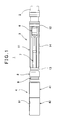
FIG.1 is an overall side view of an inner diameter measuring device according to an embodiment of the present invention. -
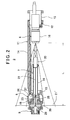
FIG.2 is a cross-sectional view of a non-contact measuring unit of the inner diameter measuring device. -
FIG.3 is a cross-sectional view of a contact measuring unit of the inner diameter measuring device. -
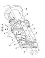
FIG. 4 is a perspective view of the contact measuring unit in a condition where a circulation unit cover and a measuring head cover are removed. -
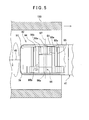
FIG. 5 is a cross-sectional view of a contact measuring head according to another example of the present invention. -
FIG.6A and FIG.6B are explanatory drawings of a linear scale in a second embodiment. -
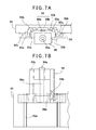
FIG.7A is a plane view of a contact measuring head, andFIG. 7B is a front view of a condition where the contact measuring unit is protruded. - Description will be given below on an embodiment of the present invention by referring to the attached drawings.
-
FIG. 1 shows an embodiment according to the present invention. InFIG.1 ,reference numeral 1 denotes an inner diameter measuring device, andreference numeral 2 denotes a rod-like supporting member for supporting the inner diametermeasuring device 1. - The inner
diameter measuring device 1 is designed in a shape, which can be included in a cylindrical surface. The cylindrical surface can also include the supportingmember 2 and the cylindrical surface is designed to be shorter than the inner diameter of a hollow portion of an object to be measured. - The inner diameter
measuring device 1 comprises anon-contact measuring unit 3 and acontact measuring unit 4. The non-contact measuringunit 3 and thecontact measuring unit 4 are arranged along an extension of a center line of the supportingmember 2. Further, the non-contact measuringunit 3 and thecontact measuring unit 4 are arranged in such manner that thecontact measuring unit 4 can be connected or disconnected from each other. - First, description will be given on the non-contact measuring
unit 3 by referring toFIG.2 . - The
non-contact measuring unit 3 primarily comprises animage pickup unit 6, a laserbeam emitting unit 7, acentering unit 8, a laserbeam diffusing unit 9, aframe unit 11, etc. Also, an optical axis of theimage pickup unit 6, an optical axis of the laserbeam emitting unit 7, a center line of thecentering unit 8, a center line of the laserbeam diffusing unit 9, and a center line of theframe unit 11 coincide with the center line of the supportingmember 2. - The
frame unit 11 is constituted in such a manner that abase end ring 12 and aforward end ring 13 are connected with each other by a plurality of supportingpillars 14. The supportingpillars 14 are arranged on the same circumference at positions with predetermined distance, e.g. at three equally distanced positions. At the center of theframe unit 11, a space penetrating from the base end to the forward end is formed. - The
image pickup unit 6 is mounted on thebase end ring 12. Theimage pickup unit 6 has acamera holder 15 to be mounted on thebase end ring 12 and acamera 16 to be accommodated in thecamera holder 15. Thecamera holder 15 is connected to the supportingmember 2. An optical axis of thecamera 16 coincides with the center line of the supportingmember 2 and the center line of theframe unit 11. - The
camera 16 has a CCD or a CMOS sensor, etc., which is an aggregate of pixels, as an image pickup element. The image pickup element outputs digital image signals, which are an aggregate of signals from each pixel, and it is so arranged that signals from each pixel can identify positions respectively within the image pickup element. - The
centering unit 8 is fixed on theforward end ring 13, and the laserbeam diffusing unit 9 is fixed on a forward end of thecentering unit 8. Anaxis adjusting mechanism 18 is accommodated in thecentering unit 8, and the laserbeam emitting unit 7 is mounted on a base end side of theaxis adjusting mechanism 18. - The laser
beam emitting unit 7 has alight emitter holder 19 of pipe-like shape to be fixed on theaxis adjusting mechanism 18, and alaser emitter 20 fitted into and attached to the base end portion of thelight emitter holder 19, and an optical axis of thelaser beam 21 emitted from thelaser emitter 20 coincides with optical axis of thecamera 16 and with the center line of theframe unit 11. - On a central part of the
axis adjusting mechanism 18, anoptical path hole 23 where thelaser beam 21 passes through is formed. Theaxis adjusting mechanism 18 has anX-axis slider 25, which perpendicularly crosses thelaser beam 21 and slides in a direction perpendicular to paper surface, and also, has a Y-axis slider 26, which is provided on theX-axis slider 25 and slides in a direction in parallel to the paper surface. It is so arranged that positions of theX-axis slider 25 and the Y-axis slider 26 can be adjusted by adjusting screws (not shown) respectively. - The
light emitter holder 19 is mounted on the Y-axis slider 26. Further, thelight emitter holder 19 is fixed at three equally divided positions on circumference by fixingmeans 27 having a pair of pushing screw and pulling screw. By adjusting the fixing means 27, tilting of the center line of thelight emitter holder 19, i.e. tilting of optical axis of thelaser beam 21 can be adjusted. - It is so arranged that a position of an optical axis of the
laser beam 21 can be adjusted in two directions perpendicularly crossing each other, i.e. in X-axis direction and in Y-axis direction, and a tilting of the optical axis can be adjusted by the fixing means 27, and also, that optical axis of thelaser beam 21 can coincide with a center line of theimage pickup unit 6 and a center line of a cone mirror 29 (to be described later). - At a forward end of the centering
unit 8, a laserbeam diffusing unit 9 is provided, and the laserbeam diffusing unit 9 has acone mirror 29 on the center line and a total circumferentiallight transmitting window 30, which is concentric to thecone mirror 29. Thecone mirror 29 has a conical curved surface with an end pointed toward thelaser emitter 20, and vertical angle of the curved surface is set to 90°, for instance. Thecone mirror 29 can be changed as appropriate to the one having different vertical angle, depending on the measurement circumstance, e.g. with vertical angle of 120° or 60°. - Under the condition that the center line of the
cone mirror 29, the optical axis of thelaser beam 21, and the optical axis of thecamera 16 coincide with each other, when thelaser beam 21 is projected from thelaser emitter 20, thelaser beam 21 enters vertex of thecone mirror 29 and is reflected in total circumferential direction by conical curved surface. When a reflected laser beam 21' which passed through the total circumferentiallight transmitting window 30 is projected to inner surface of hollow portion, an optical ring is formed. The optical ring is picked up by thecamera 16. - It is to be noted that there may be two or four supporting
pillars 14. There is no problem in so far as the supportingpillars 14 can support theimage pickup unit 6, the centeringunit 8, and the laserbeam diffusing unit 9, and no trouble is caused in the image pickup of theimage pickup unit 6. - As shown in
FIG. 2 , it is supposed that field angle of thecamera 16 is θ, and that a field angle is θ1, which is turned to a dead angle as the field angle is intercepted by thelaser emitter 20, the centeringunit 8, etc. Then, inner diameter of a hollow portion can be measured in the range of (θ1 to θ). If it is supposed that a distance from thecamera 16 to the vertex of thecone mirror 29 is L, the range of inner diameter, which can be measured, will be: (2L tan θ1/2 to 2L tan θ/2). - A measuring unit main part (not shown) has an image processing unit. The image processing unit processes the image picked up by the
camera 16, and measures an inner diameter and a shape (true circle, ellipse, etc.), or at least one of the inner diameter and the shape. Further, under the condition that the reflected laser beam 21' is projected, when the innerdiameter measuring device 1 is moved in axial direction, and images are acquired, an information such as condition of inner surface, e.g. taper, graded step, etc., can be acquired. - By referring to
FIG. 3 andFIG. 4 , description will be given on thecontact measuring unit 4. - In
FIG.3 andFIG.4 ,reference numeral 41 denotes a circulation unit,reference numeral 42 denotes a contact measuring head, andreference numeral 43 denotes a center line of thecontact measuring unit 4. - First, description will be given on the
circulation unit 41. - A center line of the
circulation unit 41 coincides with a center line of the supportingmember 2 and with a center line of thenon-contact measuring unit 3. Further, aconnection adapter 44 is provided at a base end, and thecirculation unit 41 is connected to thenon-contact measuring unit 3 via theconnection adapter 44 or thecirculation unit 41 is connected with the supportingmember 2. - A
shaft holder 45, which is hollow, is mounted on theconnection adapter 44. A center line of theshaft holder 45 coincides with thecenter line 43, and acirculation shaft 48 is rotatably supported around thecenter line 43 viabearings circulation shaft 48 is designed as hollow. - At a forward end (on the left side in
FIG.3 ) of thecirculation shaft 48, acirculation flange 49 is formed. Further, on base side of thecirculation flange 49, acirculation gear 51 is engaged with thecirculation shaft 48. - At a position as required on outer surface of the
shaft holder 45, acirculation motor 52 is provided. Acirculation driving gear 53 is fitted and fixed on an output shaft of thecirculation motor 52, and thecirculation driving gear 53 is engaged with thecirculation gear 51. Further, thecirculation motor 52 has an encoder (not shown), and the amount of rotation of thecirculation driving gear 53, i.e. the amount of rotation of thecirculation gear 51, can be detected. - At a position as required on the
shaft holder 45 and at a position not interfering with thecirculation motor 52, acirculation restricting means 54 of thecirculation flange 49 is provided. As one example of thecirculation restricting means 54, alimit switch 55 is provided on theshaft holder 45, and aswitch operating piece 56 to operate thelimit switch 55 is attached on thecirculation flange 49. In the present embodiment, a proximity switch is used as thelimit switch 55, and a metal piece, which is set so as to face each other thelimit switch 55 at an interval as required, is used as theswitch operating piece 56. - A
circulation unit cover 58 in cylindrical shape to cover theconnection adapter 44, theshaft holder 45, thecirculation flange 49, thecirculation motor 52 and thecirculation restricting means 54 is provided to stretch over from the base end of theconnection adapter 44 to thecirculation flange 49. Thecirculation unit cover 58 is not contacted with thecirculation flange 49. - Next, description will be given on the
contact measuring head 42. - The
contact measuring head 42 has acirculation base plate 61 at base end, and since thecirculation base plate 61 is fixed on thecirculation flange 49, thecirculation unit 41 and thecontact measuring head 42 are connected with each other and it is so comprised that thecirculation unit 41 and thecontact measuring head 42 are integrated with each other. Thecontact measuring head 42 is concentric with thecirculation unit 41, i.e. thecontact measuring head 42 is concentric with the laserbeam emitting unit 7. That is, thecirculation unit 41, thecontact measuring head 42 and the laserbeam emitting unit 7 are so arranged that the center line and the optical axis of each of thecirculation unit 41, thecontact measuring head 42 and the laserbeam emitting unit 7 coincide with thecenter line 43. - A measuring unit supporting
base plate 62 is provided vertically on thecirculation base plate 61, and an advancing/retreatingunit 63 and ascale unit 64 are provided on the measuring unit supportingbase plate 62. - First, description will be given on the advancing/ retreating
unit 63. - An advancing/retreating
guide rail 65 extending in a direction perpendicularly crossing thecenter line 43 is provided on the measuring unit supportingbase plate 62. A measuringunit holder 66 is slidably provided on the advancing/retreatingguide rail 65, and acontact measuring unit 67 is provided on the measuringunit holder 66. Measuring direction of thecontact measuring unit 67 is in parallel to advancing/retreating direction of the measuringunit holder 66. That is, thecontact measuring unit 67 is so arranged that it is moved in radial direction, and thecontact measuring unit 67 measures displacement in radial direction. As thecontact measuring unit 67, an electric micrometer is used, for instance. - An advancing/retreating
motor 68 is integrally provided on the measuringunit holder 66. The advancing/retreatingmotor 68 has anoutput shaft 69 extending in parallel to thecenter line 43, and apinion gear 71 is fitted on theoutput shaft 69. On the measuring unit supportingbase plate 62, arack 72 is fixed in a direction to perpendicularly cross thecenter line 43, and thepinion gear 71 is engaged with therack 72. - It is to be noted that in the figure,
reference numeral 73 denotes an escape hole to avoid interference with theoutput shaft 69. When the advancing/retreatingmotor 68 is driven, thepinion gear 71 is rotated and it is so arranged that the advancing/retreatingmotor 68 and the advancing/retreatingunit 63 are integrally moved forward or backward in radial direction (in up-to bottom direction in the figure). - It is to be noted that in the figure,
reference numeral 75 denotes a contact. Thecontact 75 is brought into contact with a measuring point, and a displacement of thecontact 75 is detected by thecontact measuring unit 67. - The
scale unit 64 has alinear scale 76 disposed in parallel to the advancing/retreatingguide rail 65 and ascale sensor 77 integrally provided with the measuringunit holder 66, and thescale sensor 77 is displaced integrally with displacement of the measuringunit holder 66. It is so arranged that thescale sensor 77 reads displacement amount from thelinear scale 76, and that thescale sensor 77 detects displacement in radial direction of the measuringunit holder 66. - Further, a measured value to be read by the
scale sensor 77 and a position of thecontact 75 are a known value A. For instance, when the known value A is added to the measured value of thescale sensor 77, a distance from thecenter line 43 to thecontact 75 can be obtained. - An amount of advancing/retreating of the measuring
unit holder 66, i.e. a stroke of thecontact measuring unit 67, is related to measurement range of inner diameter, which can be measured by thecontact measuring unit 4. Therefore, stroke of thecontact measuring unit 67 is set to the stroke, which can cover measuring range (2L tan θ1/2 to 2L tan θ/2) of thenon-contact measuring unit 3. - It is to be noted that in the figure,
reference numeral 78 denotes a cable holder to fix cables and the like (not shown). - The measuring unit supporting
base plate 62, the advancing/retreatingunit 63, thescale unit 64, thecable holder 78, etc. are covered by a measuringhead cover 79 in cylindrical shape, and ameasurement window 81 is prepared on the measuringhead cover 79 so that thecontact measuring unit 67 can protrude. An outer diameter of the measuringhead cover 79 is the same as diameter of thecirculation unit cover 58, and is shorter than inner diameter of the object to be measured. - Further, an arrangement and a weight of the components (the measuring
unit holder 66, the advancing/retreatingmotor 68, thescale sensor 77, etc.) of thecontact measuring head 42 are set up so that a center of gravity of thecontact measuring head 42 exists on thecenter line 43 or approximately on thecenter line 43 or that in a case where the measuringunit holder 66 is moved, the center of gravity of thecontact measuring head 42 exist within a predetermined range with thecenter line 43 as the center. Further, in a case where the position of the center of gravity does not come on thecenter line 43 only by the arrangement of the components, the position of the center of gravity of thecontact measuring head 42 is adjusted by providing a balance weight as appropriate. Here, the predetermined range means a range where no variation occurs on the measured value due to decentering from the center of gravity when thecontact measuring head 42 is circulated. - Description will be given below about operation.
- The inner
diameter measuring device 1 as supported on the supportingmember 2 is inserted into a hollow object to be measured (e.g. a pipe to be measured) on non-contact basis. When the innerdiameter measuring device 1 is to be inserted, thecontact 75 is set to a condition where thecontact 75 is completely retreated from outer surface of the measuringhead cover 79. - Measurement is performed while the inner
diameter measuring device 1 is being inserted into the pipe to be measured. The pipe to be measured may be moved while the innerdiameter measuring device 1 is fixed, or the innerdiameter measuring device 1 may be moved while the pipe to be measured is fixed. When the inner diameter measuring device is fixed and the pipe to be measured is moved, a measurement condition is stable because a vibration caused by the movement is not applied on the innerdiameter measuring device 1. - When a
laser beam 21 is projected from thelaser emitter 20, thelaser beam 21 is reflected over total circumference by thecone mirror 29. Reflected laser beam 21' passes through the total circumferentiallight transmitting window 30 and is projected to inner surface of the hollow portion, and an optical ring is formed. An image of this optical ring is picked up by thecamera 16, and an image data is transmitted to the measuring unit main part. A diameter, and further, a profile are measured by image processing at the measuring unit main part. Measurement results are stored in a storage unit of the measuring unit main part. - Further, at the same time, an inner diameter is measured by the
contact measuring unit 4. - By the advancing/retreating
unit 63, the measuringunit holder 66 is moved immediately before the position where thecontact 75 is brought into contact with inner surface. Then, by moving gradually, thecontact 75 is brought into contact with inner surface of the object to be measured. At this moment, from a detected value of thecontact measuring unit 67 and from an amount of moving of the measuringunit holder 66 detected by thescale sensor 77, the inner diameter of the object to be measured can be measured. - Further, the
circulation motor 52 is driven, andcirculation shaft 48 is rotated via thecirculation driving gear 53 and thecirculation gear 51. Further, thecontact measuring head 42 is rotated via thecirculation flange 49. By rotating thecontact measuring head 42 at a predetermined angular pitch, the inner diameter can be measured over total circumference of the object to be measured. - In this case, because position of the center of gravity of the
contact measuring head 42 is set on thecenter line 43, a deviation of the measuring point and a change of measurement result due to the rotation of thecontact measuring head 42 can be prevented. Further, because the profile of the hollow portion can be identified by measurement of thenon-contact measuring unit 3, points to be measured by thecontact measuring unit 4 may be fewer, so the measurement time can be shortened. Measurement results by thecontact measuring unit 4 are stored in storage unit of the measuring unit main part. - When the measurement of total inner circumference by the
contact measuring unit 4 has been completed, the innerdiameter measuring device 1 is moved by a predetermined distance in axial direction, and measurements by thenon-contact measuring unit 3 and thecontact measuring unit 4 are repeated. It is to be noted that, if a moving distance and a moving pitch are set up so that the points to be measured by thecontact measuring unit 4 are measured by thenon-contact measuring unit 3, the result measured by thenon-contact measuring unit 3 can be corrected by thecontact measuring unit 4, and a measurement accuracy of thenon-contact measuring unit 3 can be improved. - By measuring the inner diameter according to the present embodiment, the inner diameter can be measured with high accuracy by the
contact measuring unit 4, and at the same time, the profiling of inner surface by thenon-contact measuring unit 3 can be carried out. Further, by combining a contact type measurement by thecontact measuring unit 4 and a non-contact type measurement by thenon-contact measuring unit 3, the time required for the measurement can be shortened. - Further, because the
non-contact measuring unit 3 and thecontact measuring unit 4 are designed in such shapes that these can be included within the same cylindrical surface, and further, since an outer diameter of the supportingmember 2 is smaller than the cylindrical surface, by setting the supportingmember 2 to a length corresponding to the length of the pipe to be measured, even when the pipe to be measured is a long member, it is possible to perform the measurement of inner diameter and the measurement of profile over total length. - Further, the measurement by the
non-contact measuring unit 3 and the measurement by thecontact measuring unit 4 may be carried out at the same time as described above, or the measurement may be carried out by one of them. - Next, by referring to
FIG. 5 to FIG.7 , description will be given below on other examples of thecontact measuring head 42. - The
contact measuring head 42 comprises a measuring unit supportingbase plate 91, a first linear guide 92 (92a and 92b), and a second linear guide 93 (93a and 93b), a table 94 movably supported on the measuring unit supportingbase plate 91 via the linear guides 92 and 93, acontact measuring unit 95 to be disposed on front surface of the table 94, and alinear scale 96, which has ascale 96a to be disposed on back surface of the table 94 and a detecting means 96b to be disposed on the measuring unit supportingbase plate 91 so as to oppose thescale 96a. - As shown in
FIG.5 , the measuring unit supportingbase plate 91 is fixed perpendicularly on thecirculation unit 41 and rotates integrally with the rotation of thecirculation unit 41. Further, the measuring unit supportingbase plate 91 supports the table 94, which holds thecontact measuring unit 95 via the linear guides 92 and 93. - The first linear guide 92 has two sets of an advancing/ retreating
guide rails 92a and ablock 92b, and the second linear guide 93 has two sets of an advancing/retreatingguide rail 93a and ablock 93b. On each of the linear guides 92 and 93, the advancing/retreatingguide rails blocks blocks guide rails -
FIG.6A is a front view of the measuring unit supportingbase plate 91, andFIG.6B is a rear view of the table 94. As shown inFIG. 5 andFIG. 6A , two advancing/retreatingguide rails 92a of the first linear guide 92 are installed perpendicularly cross thecenter line 43 of rotation of thecirculation unit 41. As shown inFIG. 5 andFIG.6B , on rear surface of the table 94, theblock 92b of the first linear guide 92 is installed respectively at a position opposite to each of the advancing/retreatingguide rails 92a. - Further, as shown in
FIG.5 andFIG.6B , on back surface of the table 94, two advancing/ retreatingguide rails 93a of the second linear guide 93 are disposed to perpendicularly cross thecenter line 43. Also, as shown inFIG. 5 andFIG. 6A , on the measuring unit supportingbase plate 91, theblock 93b of the second linear guide 93 is disposed respectively at a position to oppose each of the advancing/retreatingguide rails 93a. - Being guided by the linear guides 92 and 93, the table 94 slides in a direction to perpendicularly cross the
center line 43 on the measuring unit supportingbase plate 91. Also, thecontact measuring unit 95 held on the front surface of the table 94 is moved integrally with the table 94. The table 94 is moved slidably by the advancing/retreatingmotor 68. Because the mechanism of advancing/retreating is the same as in the contacttype measuring head 42, description is not given here. - The
contact measuring unit 95 has acontact 95a, and thecontact 95a is brought into contact with inner wall of the object to be measured 100 and measures displacement of thecontact 95a. As described above, a measuring direction of thecontact measuring unit 95 runs in parallel to advancing/ retreating direction of the table 94. That is, thecontact measuring unit 95 moves in radial direction of the space of the object to be measured 100 and measures a displacement in radial direction. A value measured by thecontact measuring unit 95 is outputted to a calculating means (not shown) via acable 95b. The measuring unit supportingbase plate 91 is fixed on thecirculation unit 41 so that acenter line 97 in measuring direction of thecontact measuring unit 95 perpendicularly crosses a rotation axis of thecirculation unit 41. - As shown in
FIG.6B , on back surface of the table 94, thescale 96a of thelinear scale 96 is provided between two advancing/retreatingguide rails 93a in parallel to the advancing/retreatingguide rails 93a. Also, at a position to oppose thescale 96 on the measuring unit supportingbase plate 91, the detecting means 96b of thelinear scale 96 is provided. Thelinear scale 96 is a means for detecting length, and a length is measured by the detectingmeans 96b in graduation of thescale 96a. - Based on a value as inputted from the
contact measuring unit 95 and on a value inputted from thelinear scale 96, the calculating means determines inner diameter of the object to be measured 100. - As described above, each of the advancing/retreating
guide rails 92a of the first linear guide 92 are installed at left-to-right symmetrical positions with thecenter line 97 of thecontact measuring unit 95 as reference. Also, each of the advancing/retreatingguide rails 93a of the second linear guide 93 are installed at left-to-right symmetrical positions with thecenter line 97 of thecontact measuring unit 95 as reference. Further, while the advancing/retreatingguide rails 92a are installed on the measuring unit supportingbase plate 91, the advancing/retreatingguide rails 93a are installed on the table 94 to oppose to the measuring unit supportingbase plate 91. Therefore, at thecontact measuring head 42, the table 94 can be supported stably in three-dimensional direction. Values can be measured accurately by thecontact measuring unit 95 and thelinear scale 96, and measurement results can be obtained with high accuracy. Also, because thelinear scale 96 is installed between the linear guides 92 and 93, stable values can be obtained. - As described above, according to the present embodiment, an accurate inner diameter can be measured with high accuracy.
- According to the present invention, an inner diameter measuring device has a non-contact measuring unit and a contact measuring unit arranged along the same center line, wherein the non-contact measuring unit comprises an image pickup unit arranged on the center line, a laser beam emitting unit, and a laser beam diffusing unit having a cone mirror, wherein a laser beam projected from the laser beam emitting unit to the cone mirror is reflected over a total circumference by the cone mirror, the image pickup unit takes an optical ring which is formed by projecting the reflected laser beam to an inner surface of a hollow portion, at least one of an inner diameter or a shape of the inner surface is measured based on an image picked up, and wherein the contact measuring unit comprises a contact measuring head and a circulation unit for circulating the contact measuring head around the center line, wherein the contact measuring head has a contact measuring unit having a contact at a forward end and for detecting a displacement of the contact, an advancing/retreating unit for advancing and retreating the contact measuring unit in radial direction, and a scale unit for measuring an advancing/retreating distance of the contact measuring unit. As a result, measurement of inner diameter can be performed with high accuracy by the contact measuring unit, and a measurement of inner diameter and a shape of inner surface can be carried out at the same time on non-contact basis by the non-contact measuring unit. Further, by combining the measurement of contact type on the contact measuring unit and the measurement of non-contact type on the non-contact measuring unit, measurement time can be shortened.
-
- 1
- Inner diameter measuring device
- 2
- Supporting member
- 3
- Non-contact measuring unit
- 4
- Contact measuring unit
- 6
- Image pickup unit
- 7
- Laser beam emitting unit
- 8
- Centering unit
- 9
- Laser beam diffusing unit
- 16
- Camera
- 18
- Axis adjusting mechanism
- 20
- Laser emitter
- 21
- Laser beam
- 29
- Cone mirror
- 41
- Circulation unit
- 42
- Contact measuring head
- 48
- Circulation shaft
- 49
- Circulation flange
- 52
- Circulation motor
- 54
- Circulation restricting means
- 62
- Measuring unit supporting base plate
- 63
- Advancing/retreating unit
- 64
- Scale unit
- 66
- Measuring unit holder
- 67
- Contact measuring unit
- 68
- Advancing/retreating motor
- 72
- Rack
- 75
- Contact
- 76
- Linear scale
- 77
- Scale sensor
- 81
- Measurement window
- 91
- Measuring unit supporting base plate
- 92
- First linear guide
- 93
- Second linear guide
- 94
- Table
Claims (6)
- An inner diameter measuring device, having a non-contact measuring unit (3) and a contact measuring unit (4) arranged along the same center line (43),
wherein said non-contact measuring unit comprises an image pickup unit (6) arranged on said center line, a laser beam emitting unit (7), and a laser beam diffusing unit (9) having a cone mirror (29), wherein a laser beam (21) projected from said laser beam emitting unit to said cone mirror is reflected over a total circumference by said cone mirror, said image pickup unit takes an optical ring which is formed by projecting the reflected laser beam to an inner surface of a hollow portion, at least one of an inner diameter or a shape of the inner surface is measured based on an image picked up, and
wherein said contact measuring unit comprises a contact measuring head (42) and a circulation unit (41) for circulating said contact measuring head around said center line, wherein said contact measuring head has a contact measuring unit (67, 95) having a contact (75, 95a) at a forward end and for detecting a displacement of said contact, an advancing/retreating unit (63) for advancing and retreating said contact measuring unit in radial direction, and a scale unit (64) for measuring an advancing/retreating distance of said contact measuring unit. - An inner diameter measuring device according to claim 1, wherein said non-contact measuring unit (3) and said contact measuring unit (4) are configured so as to be included within the same cylindrical surface.
- An inner diameter measuring device according to claim 1, further comprising a centering unit (8) arranged on the same center line (43), wherein said laser beam emitting unit (7) is mounted on said centering unit via said centering unit, the position of said centering unit can be adjusted in two directions perpendicularly crossing with respect to the center line of said laser beam (21), and also, a tilting of an optical axis of said laser beam emitting unit can be adjusted.
- An inner diameter measuring device according to claim 1, wherein said contact measuring head (42) is so arranged that a center of gravity of said contact measuring head exists within a predetermined range with said center line (43) as the center.
- An inner diameter measuring device according to claim 1, wherein said contact measuring unit (67, 95) is provided on a measuring unit holder (66) movable in radial direction along an advancing/retreating guide rail (65), a linear scale (76) is provided in parallel to said advancing/retreating guide rail, a scale sensor (77) is provided on said measuring unit holder, and the advancing/retreating distance of said contact measuring unit is measured by said scale sensor.
- An inner diameter measuring device according to claim 1 or claim 4, wherein said contact measuring head (42) has a measuring unit supporting base plate (62) circulated by said circulation unit (41), said advancing/retreating unit (63) is provided on said measuring unit supporting base plate via two sets of linear guides (92, 93), each linear guide comprises a pair of advancing/retreating guide rails (65, 92a, 93a) and a pair of blocks (92b, 93b) respectively slidably engaged with said advancing/retreating guide rail,
wherein with respect to one of the linear guides, said advancing/retreating guide rail is provided on said measuring unit supporting base plate and said block is provided on said advancing/retreating unit, and with respect to the other of the linear guides, said advancing/retreating guide rail is provided on said advancing/retreating unit and said block is provided on said measuring unit supporting base plate.
Applications Claiming Priority (2)
| Application Number | Priority Date | Filing Date | Title |
|---|---|---|---|
| JP2012026045 | 2012-02-09 | ||
| PCT/JP2013/053590 WO2013118912A1 (en) | 2012-02-09 | 2013-02-07 | Inside-diameter measurement device |
Publications (3)
| Publication Number | Publication Date |
|---|---|
| EP2813813A1 true EP2813813A1 (en) | 2014-12-17 |
| EP2813813A4 EP2813813A4 (en) | 2015-11-04 |
| EP2813813B1 EP2813813B1 (en) | 2019-11-27 |
Family
ID=48947661
Family Applications (1)
| Application Number | Title | Priority Date | Filing Date |
|---|---|---|---|
| EP13747245.2A Active EP2813813B1 (en) | 2012-02-09 | 2013-02-07 | Inside-diameter measurement device |
Country Status (4)
| Country | Link |
|---|---|
| US (1) | US9372073B2 (en) |
| EP (1) | EP2813813B1 (en) |
| JP (1) | JP5884838B2 (en) |
| WO (1) | WO2013118912A1 (en) |
Cited By (2)
| Publication number | Priority date | Publication date | Assignee | Title |
|---|---|---|---|---|
| WO2019025812A1 (en) * | 2017-08-03 | 2019-02-07 | E.V. Offshore Limited | Quantitative surface measurements by combining image and height profile data |
| EP3745117A1 (en) * | 2019-05-29 | 2020-12-02 | Subaru Corporation | Positioning device, hole inspection device, positioning method and hole insprection method |
Families Citing this family (14)
| Publication number | Priority date | Publication date | Assignee | Title |
|---|---|---|---|---|
| JP5915223B2 (en) | 2012-02-09 | 2016-05-11 | 株式会社Ihi | Inner diameter measuring device and inner diameter measuring method |
| WO2013118916A1 (en) | 2012-02-09 | 2013-08-15 | 株式会社Ihi | Inside-diameter measurement device |
| JP2013164274A (en) | 2012-02-09 | 2013-08-22 | Ihi Corp | Inner diameter measuring apparatus |
| JP5821675B2 (en) | 2012-02-09 | 2015-11-24 | 株式会社Ihi | Rotation device rotation limiter |
| JP5915222B2 (en) | 2012-02-09 | 2016-05-11 | 株式会社Ihi | Inner diameter measuring device |
| JP5880097B2 (en) | 2012-02-09 | 2016-03-08 | 株式会社Ihi | Inner diameter measuring device |
| JP5880096B2 (en) | 2012-02-09 | 2016-03-08 | 株式会社Ihi | Inner diameter measuring device |
| US9372076B2 (en) * | 2014-04-10 | 2016-06-21 | Tri Tool Inc. | System and method for automated pipe measurement and alignment |
| JP6526465B2 (en) * | 2015-04-13 | 2019-06-05 | 三洋機工株式会社 | Roundness measuring device |
| CN104976941A (en) * | 2015-08-11 | 2015-10-14 | 苏州莱测检测科技有限公司 | Device for detecting large inner diameter |
| CN108106571B (en) * | 2017-12-14 | 2020-07-31 | 南京理工大学 | Pipeline inner wall laser detection device |
| EP3951233B1 (en) * | 2020-08-04 | 2023-10-18 | Vallourec Oil And Gas France | Internal inspection device for determining a length of a tubular good |
| USD1122128S1 (en) * | 2021-09-01 | 2026-04-14 | Insulation Technology Corporation | Instrument for testing the roundness of the inner wall of a pipe or other hollow cylinder |
| CN113928805B (en) * | 2021-09-23 | 2023-07-14 | 南京琪胜金属精密材料有限公司 | Automatic integral type metal connector direction detection device |
Family Cites Families (90)
| Publication number | Priority date | Publication date | Assignee | Title |
|---|---|---|---|---|
| US1664851A (en) | 1926-08-18 | 1928-04-03 | Gisholt Machine Co | Tool post |
| US1721524A (en) | 1927-10-03 | 1929-07-23 | Charles E Moore | Feed-screw limit gauge for lathes |
| US2822620A (en) | 1954-12-27 | 1958-02-11 | John C Ulfeldt | Gauge for measuring inside diameters |
| US3247732A (en) | 1963-10-16 | 1966-04-26 | A E Moore Company Inc | Reversible drive mechanism |
| US3436967A (en) | 1965-08-18 | 1969-04-08 | Aircraft Radio Corp | Mechanical suppressor for jittery shaft |
| US3771350A (en) | 1971-12-30 | 1973-11-13 | Aviat Inc | Pipeline leak detector |
| GB1388475A (en) | 1972-02-08 | 1975-03-26 | Dale Ltd John | Flaw detector |
| JPS50159355A (en) | 1974-06-12 | 1975-12-23 | ||
| US4045877A (en) | 1976-03-11 | 1977-09-06 | Sunnen Products Company | Retractable dial bore gauge |
| IT1133314B (en) | 1980-06-02 | 1986-07-09 | Finike Italiana Marposs | MANUAL BUFFER DIAL GAUGE FOR CHECKING THE DIAMETER OF HOLES |
| JPS5866809A (en) | 1981-09-28 | 1983-04-21 | サミユエル・ロスステイン | Measuring probe for inner surface form of pipe |
| JPS59187155A (en) | 1983-04-06 | 1984-10-24 | Hitachi Ltd | Rotary motion conversion device |
| US4536963A (en) | 1983-08-29 | 1985-08-27 | Mitutoyo Mfg. Co., Ltd. | Digital indication type measuring machine |
| GB2167559B (en) | 1984-04-20 | 1988-06-15 | Mitutoyo Mfg Co Ltd | Coordinate measuring instrument |
| JPS61102811U (en) * | 1984-12-10 | 1986-06-30 | ||
| JPS61144551A (en) | 1984-12-18 | 1986-07-02 | Toshiba Corp | Long hole peripheral wall inspecting device |
| JPS61282659A (en) | 1985-06-10 | 1986-12-12 | Fuji Electric Co Ltd | Turning-range limiting mechanism for turning shaft |
| JPH0733996B2 (en) * | 1986-08-26 | 1995-04-12 | 三菱電機株式会社 | Pipe inner surface shape detector |
| JPS63159708A (en) | 1986-12-24 | 1988-07-02 | Seiko Instr & Electronics Ltd | Shaft center detector for cylindrical body |
| IT1213696B (en) | 1987-10-09 | 1989-12-29 | Marposs Spa | APPARATUS FOR THE CONTROL OF LINEAR DIMENSIONS OF PIECES |
| JPH01195309A (en) | 1988-01-29 | 1989-08-07 | Sumitomo Rubber Ind Ltd | Measuring instrument for cylindrical body |
| US4872269A (en) | 1988-04-08 | 1989-10-10 | Karl Sattmann | Automatic cylinder profiling gage |
| FR2631697B1 (en) | 1988-05-17 | 1991-07-26 | Hispano Suiza Sa | APPARATUS FOR OPTICAL CONTROL OF THE INTERNAL PROFILE OF A TUBE OR BORE |
| DE3841439A1 (en) | 1988-12-09 | 1990-06-13 | Pietzsch Automatisierungstech | DEVICE FOR SIMULTANEOUSLY MEASURING CYLINDER HOLES BEING ABOVE |
| US4937524A (en) | 1989-04-24 | 1990-06-26 | The Babcock & Wilcox Company | Rotating eddy current roller head for inspecting tubing |
| JPH0562573A (en) | 1991-06-18 | 1993-03-12 | Fuji Electric Co Ltd | Photoelectric switch |
| US5259119A (en) | 1991-09-17 | 1993-11-09 | Mitutoyo Corporation | Automatic inner diameter measuring apparatus and zero adjustment thereof |
| US5224274A (en) | 1992-03-12 | 1993-07-06 | The Edmunds Manufacturing Company | Contact gage |
| JP2531488B2 (en) | 1993-08-10 | 1996-09-04 | 株式会社機動技研 | In-pipe measurement method |
| JPH0729405U (en) | 1993-11-01 | 1995-06-02 | 三菱重工業株式会社 | Pipe inner surface inspection device |
| JPH07191269A (en) | 1993-12-27 | 1995-07-28 | Y S Opt:Kk | Inside observation device |
| JPH0814874A (en) | 1994-06-27 | 1996-01-19 | Tosok Corp | Measuring device |
| JPH0893876A (en) | 1994-09-28 | 1996-04-12 | Mitsubishi Heavy Ind Ltd | Excessive revolution preventive structure of rotation shaft |
| JP3338571B2 (en) | 1994-11-22 | 2002-10-28 | アスモ株式会社 | Moving object position detection device |
| FR2730304B3 (en) | 1995-02-07 | 1997-04-18 | Arnould Denis | MECHANICAL METROLOGY APPARATUS FOR MEASURING BOREWORK AND LARGE CONES |
| JPH08340662A (en) * | 1995-04-13 | 1996-12-24 | Nachi Fujikoshi Corp | Centering measuring device and measuring method |
| WO1997002480A1 (en) | 1995-06-30 | 1997-01-23 | The United States Of America, Represented By The Secretary Of The Air Force | Electro-optic, noncontact, interior cross-sectional profiler |
| JPH09311034A (en) * | 1996-05-23 | 1997-12-02 | Sumitomo Metal Ind Ltd | Method and device for measuring inner diameter and inner circumference of steel pipe |
| US5933231A (en) | 1996-07-10 | 1999-08-03 | Industrial Technology Institute | Method and system for measuring cavities and probe for use therein |
| JPH10137962A (en) | 1996-11-07 | 1998-05-26 | Matsushita Electric Ind Co Ltd | Laser optics |
| JPH10197215A (en) | 1996-12-19 | 1998-07-31 | Westinghouse Electric Corp <We> | Optical inspection equipment for inner walls of tubular products |
| JP3700805B2 (en) | 1997-01-30 | 2005-09-28 | 石川島播磨重工業株式会社 | Long shaft inner diameter run-out measuring device |
| GB9719514D0 (en) | 1997-09-12 | 1997-11-19 | Thames Water Utilities | Non-contact measuring apparatus |
| US6427353B1 (en) | 1998-05-28 | 2002-08-06 | Rockwell Automation Technologies, Inc. | High speed acquisition and calculation of dimensional variables with vibration and skew error reduction |
| JP2000136923A (en) | 1998-11-04 | 2000-05-16 | Kubota Corp | Contact type pipe inner diameter measuring device |
| JP2000146564A (en) | 1998-11-04 | 2000-05-26 | Kubota Corp | Accuracy check device of contact type pipe inside diameter measuring device |
| US6243962B1 (en) | 1999-02-10 | 2001-06-12 | Samsomatic, Ltd. | Boring apparatus with shaft mounted diameter gage |
| JP2002022671A (en) | 2000-07-12 | 2002-01-23 | Nissan Motor Co Ltd | Cylindrical inner wall surface inspection device and inspection method |
| JP2002148036A (en) | 2000-11-10 | 2002-05-22 | Mitsubishi Heavy Ind Ltd | Equipment for monitoring inside diameter of tube |
| US20040189987A1 (en) * | 2000-11-15 | 2004-09-30 | Quest Integrated Inc. | A method for reformer tube in situ inspection radius calculation |
| JP4085616B2 (en) | 2001-11-01 | 2008-05-14 | 株式会社日立プラントテクノロジー | Inner surface shape measuring method and apparatus |
| US6931149B2 (en) * | 2002-04-19 | 2005-08-16 | Norsk Elektro Optikk A/S | Pipeline internal inspection device and method |
| JP2003329606A (en) | 2002-05-09 | 2003-11-19 | Tohoku Techno Arch Co Ltd | Inner surface inspection device |
| JP3869360B2 (en) | 2002-12-27 | 2007-01-17 | 三鷹光器株式会社 | Rotational support structure for surgical microscope |
| JP2004176852A (en) | 2002-11-28 | 2004-06-24 | Moriyama Giken:Kk | Rotor stopper and wind power generator using the same |
| JP4230408B2 (en) | 2004-04-30 | 2009-02-25 | 独立行政法人科学技術振興機構 | Deep hole measuring device and deep hole measuring method |
| JP2005331333A (en) * | 2004-05-19 | 2005-12-02 | Mitsubishi Heavy Ind Ltd | Shaft tube inner diameter measuring system and automatic shaft tube inner diameter measuring system |
| JP3105724U (en) | 2004-06-04 | 2004-11-25 | 株式会社環境システム | Pipe inner diameter measuring device |
| US7189023B2 (en) | 2004-09-01 | 2007-03-13 | Micro-Star Int'l Co., Ltd. | Rotational positioning apparatus |
| JP2006153546A (en) | 2004-11-26 | 2006-06-15 | Sanyo Special Steel Co Ltd | Contact-type steel pipe dimension measuring device |
| JP4508849B2 (en) | 2004-11-30 | 2010-07-21 | 株式会社ケンウッド | Stopper structure of rotary knob |
| US7111407B2 (en) | 2004-11-30 | 2006-09-26 | Tennessee Valley Authority | Vertical shaft alignment tool |
| JP4192901B2 (en) | 2005-02-17 | 2008-12-10 | 三菱電機株式会社 | Antenna device |
| JP4641824B2 (en) | 2005-02-24 | 2011-03-02 | 株式会社クボタ | In-pipe inspection device |
| US7328520B2 (en) | 2005-06-17 | 2008-02-12 | The Technologies Alliance, Inc. | Gage for measuring diameters |
| JP2007057305A (en) | 2005-08-23 | 2007-03-08 | Mitsubishi Electric Engineering Co Ltd | Internal inspection device of cylinder |
| JP2007071852A (en) | 2005-09-02 | 2007-03-22 | Akio Katsuki | Apparatus and method for measuring deep hole |
| CH705706B1 (en) | 2005-11-03 | 2013-05-15 | Belimo Holding Ag | Actuator with a reduction gear for an actuator for controlling a gas or liquid stream. |
| FR2898671B1 (en) | 2006-03-14 | 2008-12-26 | Snecma Sa | SYSTEM FOR MEASURING RATINGS WITHIN A HOLLOW SHAFT, IN PARTICULAR AERONAUTICAL TURBOMACHINE |
| JP2007292699A (en) | 2006-04-27 | 2007-11-08 | Asmo Co Ltd | Surface inspection method of member |
| DE202006017076U1 (en) | 2006-11-08 | 2007-01-04 | Fraunhofer-Gesellschaft zur Förderung der angewandten Forschung e.V. | Device for inspection of a pipeline |
| US20090144999A1 (en) | 2006-11-30 | 2009-06-11 | Lau Kam C | Interior contour measurement probe |
| JP2011524528A (en) | 2008-06-18 | 2011-09-01 | クリス−マリネ・エービー | Measuring device |
| US8164758B2 (en) | 2008-07-10 | 2012-04-24 | Quest Metrology, LLC | Internal inspection system and method |
| JP2010019783A (en) | 2008-07-14 | 2010-01-28 | Mitsutoyo Corp | Inner diameter gage |
| US8035823B2 (en) | 2008-09-05 | 2011-10-11 | 3Dm Devices Inc. | Hand-held surface profiler |
| JP2010101689A (en) * | 2008-10-22 | 2010-05-06 | Toyota Motor Corp | Apparatus and method for measuring inside diameter of circular hole |
| NO333307B1 (en) | 2008-11-24 | 2013-04-29 | Statoil Asa | Apparatus and method for optical measurement of the thickness of any deposit of material on the interior wall of a structure |
| JP2010164334A (en) | 2009-01-13 | 2010-07-29 | Ihi Corp | Device and method for measuring inside shape |
| JP2011002439A (en) | 2009-06-22 | 2011-01-06 | Kentaro Iguchi | Inspection apparatus |
| JP5378083B2 (en) | 2009-07-01 | 2013-12-25 | 東亜グラウト工業株式会社 | Inner diameter measuring device and pipe inner diameter measuring system using the inner diameter measuring device |
| US20110080588A1 (en) | 2009-10-02 | 2011-04-07 | Industrial Optical Measurement Systems | Non-contact laser inspection system |
| JP5880096B2 (en) | 2012-02-09 | 2016-03-08 | 株式会社Ihi | Inner diameter measuring device |
| JP5915223B2 (en) | 2012-02-09 | 2016-05-11 | 株式会社Ihi | Inner diameter measuring device and inner diameter measuring method |
| JP2013164274A (en) | 2012-02-09 | 2013-08-22 | Ihi Corp | Inner diameter measuring apparatus |
| WO2013118916A1 (en) | 2012-02-09 | 2013-08-15 | 株式会社Ihi | Inside-diameter measurement device |
| JP5915222B2 (en) | 2012-02-09 | 2016-05-11 | 株式会社Ihi | Inner diameter measuring device |
| JP5821675B2 (en) | 2012-02-09 | 2015-11-24 | 株式会社Ihi | Rotation device rotation limiter |
| JP5880097B2 (en) | 2012-02-09 | 2016-03-08 | 株式会社Ihi | Inner diameter measuring device |
| US9188775B2 (en) | 2013-08-28 | 2015-11-17 | United Sciences, Llc | Optical scanning and measurement |
-
2013
- 2013-02-07 EP EP13747245.2A patent/EP2813813B1/en active Active
- 2013-02-07 WO PCT/JP2013/053590 patent/WO2013118912A1/en not_active Ceased
- 2013-02-07 US US14/377,237 patent/US9372073B2/en active Active
- 2013-02-07 JP JP2013557619A patent/JP5884838B2/en active Active
Cited By (4)
| Publication number | Priority date | Publication date | Assignee | Title |
|---|---|---|---|---|
| WO2019025812A1 (en) * | 2017-08-03 | 2019-02-07 | E.V. Offshore Limited | Quantitative surface measurements by combining image and height profile data |
| US10885649B2 (en) | 2017-08-03 | 2021-01-05 | E.V. Offshore Limited | Quantitative surface measurements by combining image and height profile data |
| EP3745117A1 (en) * | 2019-05-29 | 2020-12-02 | Subaru Corporation | Positioning device, hole inspection device, positioning method and hole insprection method |
| US11300526B2 (en) | 2019-05-29 | 2022-04-12 | Subaru Corporation | Positioning device, hole inspection device, positioning method and hole inspection method |
Also Published As
| Publication number | Publication date |
|---|---|
| US20150002836A1 (en) | 2015-01-01 |
| WO2013118912A1 (en) | 2013-08-15 |
| JPWO2013118912A1 (en) | 2015-05-11 |
| EP2813813A4 (en) | 2015-11-04 |
| JP5884838B2 (en) | 2016-03-15 |
| EP2813813B1 (en) | 2019-11-27 |
| US9372073B2 (en) | 2016-06-21 |
Similar Documents
| Publication | Publication Date | Title |
|---|---|---|
| EP2813813B1 (en) | Inside-diameter measurement device | |
| US9518817B2 (en) | Inner diameter measuring device | |
| EP2818825B1 (en) | Inside-diameter measurement device and inside-diameter measurement method | |
| EP2813811B1 (en) | Inside-diameter measurement device | |
| US8964023B2 (en) | Device and method for measuring form attributes, position attributes and dimension attributes of machine elements | |
| US9372061B2 (en) | Inner diameter measuring device | |
| CN106705869A (en) | Noncontact bearing ring outside diameter measurement device | |
| CN206056522U (en) | A kind of contactless cylinder part inside/outside diameter size and form and position error measurement device | |
| US8111407B2 (en) | Displacement sensor | |
| US4785193A (en) | Process and apparatus for determination of dimensions of an elongated test object | |
| JP2009216548A (en) | Measurement apparatus | |
| US20090141131A1 (en) | Calibrating method of image measuring instrument | |
| JP5317549B2 (en) | Cam profile measuring device | |
| CN208476179U (en) | A kind of laser detection machine | |
| KR101974087B1 (en) | Measuring touch probe, measuring system, method for laser-optical determination of the height of a strand guide roller, and use of the measuring system | |
| CN118089562A (en) | Non-contact thickness gauge and thickness measuring method thereof | |
| KR100467060B1 (en) | Apparatus for measuring roughness and flatness | |
| CN209877932U (en) | Nuclear reaction column assembly installation and measurement tool | |
| CN207180613U (en) | Non-contact type bearing lasso external diameter measuring device | |
| CN106042001A (en) | Measurement device for tail spatial position of robot | |
| CN211121150U (en) | Inner diameter measuring device for processing tubular parts | |
| JP2008196962A (en) | Tire measuring device | |
| CN218120906U (en) | Full-automatic image measuring instrument for detecting tooth profile of synchronous wheel | |
| JP5363196B2 (en) | Dimension measuring device | |
| CN108571956B (en) | A kind of long-range rotating mechanism auxiliary alignment device and measurement method |
Legal Events
| Date | Code | Title | Description |
|---|---|---|---|
| PUAI | Public reference made under article 153(3) epc to a published international application that has entered the european phase |
Free format text: ORIGINAL CODE: 0009012 |
|
| 17P | Request for examination filed |
Effective date: 20140728 |
|
| AK | Designated contracting states |
Kind code of ref document: A1 Designated state(s): AL AT BE BG CH CY CZ DE DK EE ES FI FR GB GR HR HU IE IS IT LI LT LU LV MC MK MT NL NO PL PT RO RS SE SI SK SM TR |
|
| AX | Request for extension of the european patent |
Extension state: BA ME |
|
| DAX | Request for extension of the european patent (deleted) | ||
| RA4 | Supplementary search report drawn up and despatched (corrected) |
Effective date: 20151007 |
|
| RIC1 | Information provided on ipc code assigned before grant |
Ipc: G01B 11/24 20060101ALI20151001BHEP Ipc: G01B 21/14 20060101AFI20151001BHEP Ipc: G01B 5/12 20060101ALI20151001BHEP Ipc: G01B 11/12 20060101ALI20151001BHEP |
|
| GRAP | Despatch of communication of intention to grant a patent |
Free format text: ORIGINAL CODE: EPIDOSNIGR1 |
|
| STAA | Information on the status of an ep patent application or granted ep patent |
Free format text: STATUS: GRANT OF PATENT IS INTENDED |
|
| INTG | Intention to grant announced |
Effective date: 20190627 |
|
| GRAS | Grant fee paid |
Free format text: ORIGINAL CODE: EPIDOSNIGR3 |
|
| GRAA | (expected) grant |
Free format text: ORIGINAL CODE: 0009210 |
|
| STAA | Information on the status of an ep patent application or granted ep patent |
Free format text: STATUS: THE PATENT HAS BEEN GRANTED |
|
| AK | Designated contracting states |
Kind code of ref document: B1 Designated state(s): AL AT BE BG CH CY CZ DE DK EE ES FI FR GB GR HR HU IE IS IT LI LT LU LV MC MK MT NL NO PL PT RO RS SE SI SK SM TR |
|
| REG | Reference to a national code |
Ref country code: GB Ref legal event code: FG4D |
|
| REG | Reference to a national code |
Ref country code: CH Ref legal event code: EP |
|
| REG | Reference to a national code |
Ref country code: AT Ref legal event code: REF Ref document number: 1207180 Country of ref document: AT Kind code of ref document: T Effective date: 20191215 |
|
| REG | Reference to a national code |
Ref country code: DE Ref legal event code: R096 Ref document number: 602013063361 Country of ref document: DE |
|
| REG | Reference to a national code |
Ref country code: IE Ref legal event code: FG4D |
|
| REG | Reference to a national code |
Ref country code: NL Ref legal event code: MP Effective date: 20191127 |
|
| REG | Reference to a national code |
Ref country code: LT Ref legal event code: MG4D |
|
| PG25 | Lapsed in a contracting state [announced via postgrant information from national office to epo] |
Ref country code: FI Free format text: LAPSE BECAUSE OF FAILURE TO SUBMIT A TRANSLATION OF THE DESCRIPTION OR TO PAY THE FEE WITHIN THE PRESCRIBED TIME-LIMIT Effective date: 20191127 Ref country code: BG Free format text: LAPSE BECAUSE OF FAILURE TO SUBMIT A TRANSLATION OF THE DESCRIPTION OR TO PAY THE FEE WITHIN THE PRESCRIBED TIME-LIMIT Effective date: 20200227 Ref country code: LV Free format text: LAPSE BECAUSE OF FAILURE TO SUBMIT A TRANSLATION OF THE DESCRIPTION OR TO PAY THE FEE WITHIN THE PRESCRIBED TIME-LIMIT Effective date: 20191127 Ref country code: SE Free format text: LAPSE BECAUSE OF FAILURE TO SUBMIT A TRANSLATION OF THE DESCRIPTION OR TO PAY THE FEE WITHIN THE PRESCRIBED TIME-LIMIT Effective date: 20191127 Ref country code: NL Free format text: LAPSE BECAUSE OF FAILURE TO SUBMIT A TRANSLATION OF THE DESCRIPTION OR TO PAY THE FEE WITHIN THE PRESCRIBED TIME-LIMIT Effective date: 20191127 Ref country code: ES Free format text: LAPSE BECAUSE OF FAILURE TO SUBMIT A TRANSLATION OF THE DESCRIPTION OR TO PAY THE FEE WITHIN THE PRESCRIBED TIME-LIMIT Effective date: 20191127 Ref country code: LT Free format text: LAPSE BECAUSE OF FAILURE TO SUBMIT A TRANSLATION OF THE DESCRIPTION OR TO PAY THE FEE WITHIN THE PRESCRIBED TIME-LIMIT Effective date: 20191127 Ref country code: NO Free format text: LAPSE BECAUSE OF FAILURE TO SUBMIT A TRANSLATION OF THE DESCRIPTION OR TO PAY THE FEE WITHIN THE PRESCRIBED TIME-LIMIT Effective date: 20200227 Ref country code: GR Free format text: LAPSE BECAUSE OF FAILURE TO SUBMIT A TRANSLATION OF THE DESCRIPTION OR TO PAY THE FEE WITHIN THE PRESCRIBED TIME-LIMIT Effective date: 20200228 |
|
| PG25 | Lapsed in a contracting state [announced via postgrant information from national office to epo] |
Ref country code: HR Free format text: LAPSE BECAUSE OF FAILURE TO SUBMIT A TRANSLATION OF THE DESCRIPTION OR TO PAY THE FEE WITHIN THE PRESCRIBED TIME-LIMIT Effective date: 20191127 Ref country code: IS Free format text: LAPSE BECAUSE OF FAILURE TO SUBMIT A TRANSLATION OF THE DESCRIPTION OR TO PAY THE FEE WITHIN THE PRESCRIBED TIME-LIMIT Effective date: 20200327 Ref country code: RS Free format text: LAPSE BECAUSE OF FAILURE TO SUBMIT A TRANSLATION OF THE DESCRIPTION OR TO PAY THE FEE WITHIN THE PRESCRIBED TIME-LIMIT Effective date: 20191127 |
|
| PG25 | Lapsed in a contracting state [announced via postgrant information from national office to epo] |
Ref country code: AL Free format text: LAPSE BECAUSE OF FAILURE TO SUBMIT A TRANSLATION OF THE DESCRIPTION OR TO PAY THE FEE WITHIN THE PRESCRIBED TIME-LIMIT Effective date: 20191127 |
|
| PG25 | Lapsed in a contracting state [announced via postgrant information from national office to epo] |
Ref country code: RO Free format text: LAPSE BECAUSE OF FAILURE TO SUBMIT A TRANSLATION OF THE DESCRIPTION OR TO PAY THE FEE WITHIN THE PRESCRIBED TIME-LIMIT Effective date: 20191127 Ref country code: CZ Free format text: LAPSE BECAUSE OF FAILURE TO SUBMIT A TRANSLATION OF THE DESCRIPTION OR TO PAY THE FEE WITHIN THE PRESCRIBED TIME-LIMIT Effective date: 20191127 Ref country code: EE Free format text: LAPSE BECAUSE OF FAILURE TO SUBMIT A TRANSLATION OF THE DESCRIPTION OR TO PAY THE FEE WITHIN THE PRESCRIBED TIME-LIMIT Effective date: 20191127 Ref country code: PT Free format text: LAPSE BECAUSE OF FAILURE TO SUBMIT A TRANSLATION OF THE DESCRIPTION OR TO PAY THE FEE WITHIN THE PRESCRIBED TIME-LIMIT Effective date: 20200419 Ref country code: DK Free format text: LAPSE BECAUSE OF FAILURE TO SUBMIT A TRANSLATION OF THE DESCRIPTION OR TO PAY THE FEE WITHIN THE PRESCRIBED TIME-LIMIT Effective date: 20191127 |
|
| REG | Reference to a national code |
Ref country code: DE Ref legal event code: R097 Ref document number: 602013063361 Country of ref document: DE |
|
| PG25 | Lapsed in a contracting state [announced via postgrant information from national office to epo] |
Ref country code: SK Free format text: LAPSE BECAUSE OF FAILURE TO SUBMIT A TRANSLATION OF THE DESCRIPTION OR TO PAY THE FEE WITHIN THE PRESCRIBED TIME-LIMIT Effective date: 20191127 Ref country code: SM Free format text: LAPSE BECAUSE OF FAILURE TO SUBMIT A TRANSLATION OF THE DESCRIPTION OR TO PAY THE FEE WITHIN THE PRESCRIBED TIME-LIMIT Effective date: 20191127 |
|
| REG | Reference to a national code |
Ref country code: AT Ref legal event code: MK05 Ref document number: 1207180 Country of ref document: AT Kind code of ref document: T Effective date: 20191127 |
|
| REG | Reference to a national code |
Ref country code: CH Ref legal event code: PL |
|
| PLBE | No opposition filed within time limit |
Free format text: ORIGINAL CODE: 0009261 |
|
| STAA | Information on the status of an ep patent application or granted ep patent |
Free format text: STATUS: NO OPPOSITION FILED WITHIN TIME LIMIT |
|
| REG | Reference to a national code |
Ref country code: BE Ref legal event code: MM Effective date: 20200229 |
|
| PG25 | Lapsed in a contracting state [announced via postgrant information from national office to epo] |
Ref country code: MC Free format text: LAPSE BECAUSE OF FAILURE TO SUBMIT A TRANSLATION OF THE DESCRIPTION OR TO PAY THE FEE WITHIN THE PRESCRIBED TIME-LIMIT Effective date: 20191127 Ref country code: LU Free format text: LAPSE BECAUSE OF NON-PAYMENT OF DUE FEES Effective date: 20200207 |
|
| 26N | No opposition filed |
Effective date: 20200828 |
|
| PG25 | Lapsed in a contracting state [announced via postgrant information from national office to epo] |
Ref country code: AT Free format text: LAPSE BECAUSE OF FAILURE TO SUBMIT A TRANSLATION OF THE DESCRIPTION OR TO PAY THE FEE WITHIN THE PRESCRIBED TIME-LIMIT Effective date: 20191127 Ref country code: SI Free format text: LAPSE BECAUSE OF FAILURE TO SUBMIT A TRANSLATION OF THE DESCRIPTION OR TO PAY THE FEE WITHIN THE PRESCRIBED TIME-LIMIT Effective date: 20191127 Ref country code: PL Free format text: LAPSE BECAUSE OF FAILURE TO SUBMIT A TRANSLATION OF THE DESCRIPTION OR TO PAY THE FEE WITHIN THE PRESCRIBED TIME-LIMIT Effective date: 20191127 Ref country code: LI Free format text: LAPSE BECAUSE OF NON-PAYMENT OF DUE FEES Effective date: 20200229 Ref country code: CH Free format text: LAPSE BECAUSE OF NON-PAYMENT OF DUE FEES Effective date: 20200229 |
|
| PG25 | Lapsed in a contracting state [announced via postgrant information from national office to epo] |
Ref country code: IE Free format text: LAPSE BECAUSE OF NON-PAYMENT OF DUE FEES Effective date: 20200207 Ref country code: IT Free format text: LAPSE BECAUSE OF FAILURE TO SUBMIT A TRANSLATION OF THE DESCRIPTION OR TO PAY THE FEE WITHIN THE PRESCRIBED TIME-LIMIT Effective date: 20191127 |
|
| PG25 | Lapsed in a contracting state [announced via postgrant information from national office to epo] |
Ref country code: BE Free format text: LAPSE BECAUSE OF NON-PAYMENT OF DUE FEES Effective date: 20200229 |
|
| PGFP | Annual fee paid to national office [announced via postgrant information from national office to epo] |
Ref country code: DE Payment date: 20220119 Year of fee payment: 10 |
|
| PG25 | Lapsed in a contracting state [announced via postgrant information from national office to epo] |
Ref country code: TR Free format text: LAPSE BECAUSE OF FAILURE TO SUBMIT A TRANSLATION OF THE DESCRIPTION OR TO PAY THE FEE WITHIN THE PRESCRIBED TIME-LIMIT Effective date: 20191127 Ref country code: MT Free format text: LAPSE BECAUSE OF FAILURE TO SUBMIT A TRANSLATION OF THE DESCRIPTION OR TO PAY THE FEE WITHIN THE PRESCRIBED TIME-LIMIT Effective date: 20191127 Ref country code: CY Free format text: LAPSE BECAUSE OF FAILURE TO SUBMIT A TRANSLATION OF THE DESCRIPTION OR TO PAY THE FEE WITHIN THE PRESCRIBED TIME-LIMIT Effective date: 20191127 |
|
| PGFP | Annual fee paid to national office [announced via postgrant information from national office to epo] |
Ref country code: FR Payment date: 20220120 Year of fee payment: 10 |
|
| PG25 | Lapsed in a contracting state [announced via postgrant information from national office to epo] |
Ref country code: MK Free format text: LAPSE BECAUSE OF FAILURE TO SUBMIT A TRANSLATION OF THE DESCRIPTION OR TO PAY THE FEE WITHIN THE PRESCRIBED TIME-LIMIT Effective date: 20191127 |
|
| REG | Reference to a national code |
Ref country code: DE Ref legal event code: R119 Ref document number: 602013063361 Country of ref document: DE |
|
| PG25 | Lapsed in a contracting state [announced via postgrant information from national office to epo] |
Ref country code: FR Free format text: LAPSE BECAUSE OF NON-PAYMENT OF DUE FEES Effective date: 20230228 Ref country code: DE Free format text: LAPSE BECAUSE OF NON-PAYMENT OF DUE FEES Effective date: 20230901 |
|
| PGFP | Annual fee paid to national office [announced via postgrant information from national office to epo] |
Ref country code: GB Payment date: 20260121 Year of fee payment: 14 |