EP2813649A2 - Selbstverriegelndes Antipanik-Schloss - Google Patents
Selbstverriegelndes Antipanik-Schloss Download PDFInfo
- Publication number
- EP2813649A2 EP2813649A2 EP14001605.6A EP14001605A EP2813649A2 EP 2813649 A2 EP2813649 A2 EP 2813649A2 EP 14001605 A EP14001605 A EP 14001605A EP 2813649 A2 EP2813649 A2 EP 2813649A2
- Authority
- EP
- European Patent Office
- Prior art keywords
- self
- magnet
- channel
- locking anti
- panic
- Prior art date
- Legal status (The legal status is an assumption and is not a legal conclusion. Google has not performed a legal analysis and makes no representation as to the accuracy of the status listed.)
- Granted
Links
Images

Classifications
-
- E—FIXED CONSTRUCTIONS
- E05—LOCKS; KEYS; WINDOW OR DOOR FITTINGS; SAFES
- E05B—LOCKS; ACCESSORIES THEREFOR; HANDCUFFS
- E05B47/00—Operating or controlling locks or other fastening devices by electric or magnetic means
- E05B47/06—Controlling mechanically-operated bolts by electro-magnetically-operated detents
- E05B47/0657—Controlling mechanically-operated bolts by electro-magnetically-operated detents by locking the handle, spindle, follower or the like
-
- E—FIXED CONSTRUCTIONS
- E05—LOCKS; KEYS; WINDOW OR DOOR FITTINGS; SAFES
- E05B—LOCKS; ACCESSORIES THEREFOR; HANDCUFFS
- E05B47/00—Operating or controlling locks or other fastening devices by electric or magnetic means
- E05B47/06—Controlling mechanically-operated bolts by electro-magnetically-operated detents
- E05B47/0676—Controlling mechanically-operated bolts by electro-magnetically-operated detents by disconnecting the handle
-
- E—FIXED CONSTRUCTIONS
- E05—LOCKS; KEYS; WINDOW OR DOOR FITTINGS; SAFES
- E05B—LOCKS; ACCESSORIES THEREFOR; HANDCUFFS
- E05B63/00—Locks or fastenings with special structural characteristics
- E05B63/04—Locks or fastenings with special structural characteristics for alternative use on the right-hand or left-hand side of wings
-
- E—FIXED CONSTRUCTIONS
- E05—LOCKS; KEYS; WINDOW OR DOOR FITTINGS; SAFES
- E05B—LOCKS; ACCESSORIES THEREFOR; HANDCUFFS
- E05B63/00—Locks or fastenings with special structural characteristics
- E05B63/18—Locks or fastenings with special structural characteristics with arrangements independent of the locking mechanism for retaining the bolt or latch in the retracted position
- E05B63/20—Locks or fastenings with special structural characteristics with arrangements independent of the locking mechanism for retaining the bolt or latch in the retracted position released automatically when the wing is closed
-
- E—FIXED CONSTRUCTIONS
- E05—LOCKS; KEYS; WINDOW OR DOOR FITTINGS; SAFES
- E05B—LOCKS; ACCESSORIES THEREFOR; HANDCUFFS
- E05B65/00—Locks or fastenings for special use
- E05B65/10—Locks or fastenings for special use for panic or emergency doors
- E05B65/1086—Locks with panic function, e.g. allowing opening from the inside without a ley even when locked from the outside
Definitions
- the present invention relates to a self-locking anti-panic lock with a magnetic rocker, in which a cuboid magnet is mounted.
- Self-locking anti-panic locks have a panic function and a Panikseite opposite Zuschaltseite whose function u. a. is ensured by a magnetic rocker.
- a magnetic rocker there are currently two variants, which are required for the usesverriegeinder Antipanik locks with panic function on the left and panic function right.
- the two variants differ with regard to the positioning of the magnet in the magnetic rocker. Thus, it must be decided before buying or installation, for which panic direction the self-locking anti-panic lock is to be used. A subsequent conversion is no longer possible.
- This object is achieved according to the invention in a self-locking anti-panic lock with a magnetic rocker, in which a cuboidal magnet is mounted, that the magnet is slidably mounted in a channel arranged in the magnetic rocker.
- the channel is limited at each end by a stop made of steel.
- the stop is advantageously made of a steel pin, a steel sleeve o. The like.
- the magnetic rocker is provided with two holes crossing the channel in its end regions into which the stop can be inserted.
- the magnetic rocker may be provided with two adjacent to the end portions of the channel and extending in the longitudinal direction of the channel bores into which the stopper can be inserted.
- the magnet keeps its position by its magnetic force at the respective stop and can no longer slip.
- the magnet can advantageously be moved by means of a thin tool from the outside in the channel between the two stops. Thus, an adjustment is possible at any time and without much effort.
- the magnet is advantageously formed cuboid.
- the magnet may also be formed into a cylindrical shape.
- the magnet is preferably a neodymium magnet.
- FIG. 4 the arrangement of the magnetic rocker according to the invention can be seen in a self-locking anti-panic lock.
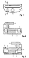
- FIG. 1 shows a plan view of a magnetic rocker according to the invention 1.
- a channel 2 is arranged, which extends transversely to the longitudinal extent of the magnetic rocker 1, as is apparent from FIG. 2 can be removed.
- a cuboidal magnet 3 is mounted, which is preferably formed by a neodymium magnet.
- the magnet 3 is displaceable in the longitudinal direction of the channel 2, by means of a thin tool, not shown, which can engage in the channel 2 from the outside.
- the channel 2 is bounded by two holes 4, which extend transversely through the channel 2.
- steel pins are used, which limit the adjustment of the magnet 3.
- the magnet 3 can thus hold depending on the situation on one or the other Stahi.
- the channel 2 is bounded by two holes 4, which adjoin the channel 2 in the longitudinal direction.
- steel sleeves 5 are used, which also extend in the longitudinal direction of the channel 2 and limit the adjustment of the magnet 3.
- the magnet 3 holds due to its magnetic force, depending on the position of one or the other steel sleeve 5 and thereby ensures the panic function on the left or the panic function on the right.
- FIG. 4 the magnetic rocker 1 according to the invention is installed in a self-locking anti-panic lock 6.
- the anti-panic lock 6 has a lock plate 7, on which a slider 8 is mounted.
- the slider 8 is connected to a latch 9, a cross-fall wing 10 and an additional trap 11 in operative connection.
- a coil 12 is also mounted, which can act on the inventively embodied magnetic rocker 1.
- the magnetic rocker 1, held by a retaining spring 13 in position is mounted on a guide pin 14 which has a in FIG. 1 shown recording 15 of the magnetic rocker 1 passes through.
Landscapes
- Engineering & Computer Science (AREA)
- Structural Engineering (AREA)
- Business, Economics & Management (AREA)
- Emergency Management (AREA)
- Lock And Its Accessories (AREA)
- Mutual Connection Of Rods And Tubes (AREA)
- Details Of Connecting Devices For Male And Female Coupling (AREA)
- Soft Magnetic Materials (AREA)
Abstract
Description
- Die vorliegende Erfindung betrifft ein selbstverriegelndes Antipanik-Schloss mit einer Magnetwippe, in welcher ein quaderförmiger Magnet gelagert ist.
- Selbstverriegelnde Antipanik-Schlösser haben eine Panikfunktion sowie eine der Panikseite gegenüberliegende Zuschaltseite, deren Funktion u. a. durch eine Magnetwippe gewährleistet wird. Von der Magnetwippe gibt es derzeit zwei Varianten, die für den Einsatz selbstverriegeinder Antipanik-Schlösser mit Panikfunktion links und Panikfunktion rechts erforderlich sind. Die zwei Varianten unterscheiden sich hinsichtlich der Positionierung des Magneten in der Magnetwippe. Somit muss vor dem Kauf bzw. Einbau entschieden werden, für welche Panikrichtung das selbstverriegelnde Antipanik-Schloss eingesetzt werden soll. Ein nachträglicher Umbau ist nicht mehr möglich.
- Es ist daher Aufgabe der vorliegenden Erfindung, ein selbstverriegelndes Antipanik-Schloss der eingangs genannten Art bereit zu stellen, welches sowohl für eine Panikfunktion links als auch für eine Panikfunktion rechts einsetzbar ist.
- Diese Aufgabe wird bei einem selbstverriegelnden Antipanik-Schloss mit einer Magnetwippe, in welcher ein quaderförmiger Magnet gelagert ist, erfindungsgemäß dadurch gelöst, dass der Magnet in einem in der Magnetwippe angeordneten Kanal verschiebbar gelagert ist.
- Durch die Verstellmöglichkeit des Magneten in der Magnetwippe kann die Richtung der Zuschaltfunktion nach Montage und Auslieferung des Schlosses beliebig oft und mit einem einfachen Werkzeug durch den Kunden umgestellt werden. Die Umstellung erfolgt von außen durch Öffnungen in der Magnetwippe, ohne dass diese geöffnet werden muss. Dadurch werden 50% der Varianten eingespart.
- Die Unteransprüche haben vorteilhafte Weiterbildungen der Erfindung zum Inhalt.
- Gemäß einer bevorzugten Weiterbildung ist der Kanal an jedem Ende durch einen aus Stahl bestehenden Anschlag begrenzt.
- Der Anschlag besteht vorteilhafterweise aus einem Stahistift, einer Stahlhülse o. dgl.
- Gemäß einer vorteilhaften Ausgestaltung ist die Magnetwippe mit zwei den Kanal in seinen Endbereichen kreuzenden Bohrungen versehen, in welche der Anschlag einsetzbar ist.
- Alternativ dazu kann die Magnetwippe mit zwei sich an die Endbereiche des Kanals anschließenden und in Längsrichtung des Kanals verlaufenden Bohrungen versehen sein, in welche der Anschlag einsetzbar ist.
- In beiden Fällen hält der Magnet seine Position durch seine Magnetkraft an dem jeweiligen Anschlag und kann nicht mehr verrutschen.
- Der Magnet kann vorteilhafterweise mittels eines dünnen Werkzeuges von außen in dem Kanal zwischen den beiden Anschlägen verschoben werden. Somit ist eine Verstellung jederzeit und ohne großen Aufwand möglich.
- Der Magnet ist vorteilhafterweise quaderförmig ausgebildet. Der Magnet kann auch in eine zylindrische Form ausgebildet sein.
- Bei dem Magneten handelt es sich vorzugsweise um einen Neodymmagnet.
- Weitere Einzelheiten, Merkmale und Vorteile der Erfindung ergeben sich aus nachfolgender Beschreibung anhand der Zeichnungen. Es zeigen:
- Figur 1
- eine Draufsicht auf eine Magnetwippe zur Verwendung in einem selbstverriegelnden Antipanik-Schloss,
- Figur 2
- einen Schnitt durch die Magnetwippe gemäß
Figur 1 entlang der Linie C - C gemäß einer ersten Ausführungsform. - Figur 3
- einen Schnitt durch die Magnetwippe gemäß
Figur 1 entlang der Linie C - C gemäß einer zweiten Ausführungsform, und - Figur 4
- eine Ansicht eines selbstverriegelnden Antipanik-Schlosses mit der erfindungsgemäßen Magnetwippe.
- Im Folgenden wird zunächst die Magnetwippe im Hinblick auf ihre erfindungsgemäße Ausgestaltung erläutert, in
Figur 4 ist die Anordnung der erfindungsgemäßen Magnetwippe in einem selbstverriegelnden Antipanik-Schloss zu sehen. -
Figur 1 zeigt eine Draufsicht auf eine erfindungsgemäße Magnetwippe 1. In der Magnetwippe 1 ist ein Kanal 2 angeordnet, der sich quer zur Längserstreckung der Magnetwippe 1 erstreckt, wie sich ausFigur 2 entnehmen lässt. In dem Kanal 2 ist ein quaderförmiger Magnet 3 gelagert, der vorzugsweise von einem Neodymmagnet gebildet ist. - Der Magnet 3 ist in Längsrichtung des Kanals 2 verschiebbar, und zwar mittels eines nicht dargestellten dünnen Werkzeuges, das von außen in den Kanal 2 eingreifen kann.
- Gemäß einer ersten, in
Figur 2 dargestellten Ausführungsform wird der Kanal 2 von zwei Bohrungen 4 begrenzt, welche sich quer durch den Kanal 2 erstrecken. In die Bohrungen 4 werden Stahlstifte eingesetzt, welche den Verstellbereich des Magneten 3 begrenzen. Infolge seiner Magnetkraft kann sich der Magnet 3 somit je nach Lage an dem einen oder dem anderen Stahistift festhalten und dadurch die Panikfunktion links oder die Panikfunktion rechts gewährleisten. - Gemäß einer zweiten, in
Figur 3 dargestellten Ausführungsform wird der Kanal 2 von zwei Bohrungen 4 begrenzt, welche sich in Längsrichtung an den Kanal 2 anschließen. In diese Bohrungen 4 werden Stahlhülsen 5 eingesetzt, welche sich ebenfalls in Längsrichtung des Kanals 2 erstrecken und den Verstellbereich des Magneten 3 begrenzen. Auch bei dieser Ausführungsform hält sich der Magnet 3 infolge seiner Magnetkraft je nach Lage an der einen oder der anderen Stahlhülse 5 fest und gewährleistet dadurch die Panikfunktion links oder die Panikfunktion rechts. - In
Figur 4 ist die erfindungsgemäße Magnetwippe 1 in ein selbstverriegelndes Antipanik-Schloss 6 eingebaut. - Das Antipanik-Schloss 6 weist ein Schlossblech 7 auf, auf dem ein Schieber 8 montiert ist. Der Schieber 8 steht mit einem Riegel 9, einem Kreuzfallenflügel 10 und einer Zusatzfalle 11 in Wirkverbindung. An dem Schlossblech 7 ist weiterhin eine Spule 12 gelagert, welche die erfindungsgemäß ausgebildete Magnetwippe 1 beaufschlagen kann. Die Magnetwippe 1, die von einer Haltefeder 13 in Position gehalten wird, ist an einem Führungsbolzen 14 gelagert, welcher eine in
Figur 1 dargestellte Aufnahme 15 der Magnetwippe 1 durchsetzt. - Die vorhergehende Beschreibung der vorliegenden Erfindung dient nur zu illustrativen Zwecken und nicht zum Zwecke der Beschränkung der Erfindung. Im Rahmen der Erfindung sind verschiedene Änderungen und Modifikationen möglich, ohne den Umfang der Erfindung sowie ihrer Äquivalente zu verlassen.
-
- 1
- Magnetwippe
- 2
- Kanal
- 3
- Magnet
- 4
- Bohrung
- 5
- Stahlhülse
- 6
- Antipanik-Schloss
- 7
- Schlossblech
- 8
- Schieber
- 9
- Riegel
- 10
- Kreuzfallenflügal
- 11
- Zusatzfalle
- 12
- Spule
- 13
- Haltefeder
- 14
- Führungsbolzen
- 15
- Aufnahme
Claims (8)
- Selbstverriegelndes Antipanik-Schloss mit einer Magnetwippe, in welcher ein Magnet gelagert ist, dadurch gekennzeichnet, dass der Magnet (3) in einem in der Magnetwippe (1) angeordneten Kanal (2) verschiebbar gelagert ist.
- Selbstverriegelndes Antipanik-Schloss nach Anspruch 1, dadurch gekennzeichnet, dass der Kanal (2) an jedem Ende durch einen aus Stahl bestehenden Anschlag begrenzt ist.
- Selbstverriegelndes Antipanik-Schloss nach Anspruch 2, dadurch gekennzeichnet, dass der Anschlag aus einem Stahlstift, einer Stahlhülse (5) o. dgl. besteht.
- Selbstverriegelndes Antipanik-Schloss nach Anspruch 2 oder 3, dadurch gekennzeichnet, dass die Magnetwippe (1) mit zwei den Kanal (2) in seinen Endbereichen kreuzenden Bohrungen (4) versehen ist, in welche der Anschlag einsetzbar ist.
- Selbstverriegelndes Antipanik-Schloss nach Anspruch 2 oder 3, dadurch gekennzeichnet, dass die Magnetwippe (1) mit zwei sich an die Endbereiche des Kanals (2) anschließenden und in Längsrichtung des Kanals verlaufenden Bohrungen (4) versehen ist, in welche der Anschlag einsetzbar ist.
- Selbstverriegelndes Antipanik-Schloss nach einem der vorhergehenden Ansprüche, dadurch gekennzeichnet, dass der Magnet (3) mittels eines dünnen Werkzeuges von außen in dem Kanal (2) zwischen den beiden Anschlägen verschiebbar ist.
- Selbstverriegelndes Antipanik-Schloss nach einem der vorhergehenden Ansprüche, dadurch gekennzeichnet, dass der Magnet (3 quaderförmig oder zylindrisch ausgebildet ist.
- Selbstverriegelndes Antipanik-Schloss nach einem der vorhergehenden Ansprüche, dadurch gekennzeichnet, dass der Magnet (3) ein Neodymmagnet ist.
Applications Claiming Priority (1)
| Application Number | Priority Date | Filing Date | Title |
|---|---|---|---|
| DE102013106088.9A DE102013106088A1 (de) | 2013-06-12 | 2013-06-12 | Selbstverriegelndes Antipanik-Schloss |
Publications (3)
| Publication Number | Publication Date |
|---|---|
| EP2813649A2 true EP2813649A2 (de) | 2014-12-17 |
| EP2813649A3 EP2813649A3 (de) | 2015-11-25 |
| EP2813649B1 EP2813649B1 (de) | 2018-08-15 |
Family
ID=50687235
Family Applications (1)
| Application Number | Title | Priority Date | Filing Date |
|---|---|---|---|
| EP14001605.6A Active EP2813649B1 (de) | 2013-06-12 | 2014-05-07 | Selbstverriegelndes Antipanik-Schloss |
Country Status (2)
| Country | Link |
|---|---|
| EP (1) | EP2813649B1 (de) |
| DE (1) | DE102013106088A1 (de) |
Cited By (1)
| Publication number | Priority date | Publication date | Assignee | Title |
|---|---|---|---|---|
| DE102022109723A1 (de) | 2022-04-22 | 2022-12-08 | Elvis Belov | Verschlussvorrichtung für Fahrzeuge |
Family Cites Families (5)
| Publication number | Priority date | Publication date | Assignee | Title |
|---|---|---|---|---|
| DE10303220B3 (de) * | 2003-01-23 | 2004-09-16 | Dom Sicherheitstechnik Gmbh & Co Kg | Schließzylinder |
| DE102007012613B4 (de) * | 2007-03-13 | 2018-03-08 | Dormakaba Deutschland Gmbh | Panikschloss |
| DE102008018297A1 (de) * | 2008-04-11 | 2009-10-15 | Cestronics Gmbh | Schließzylinder mit magnetisch gekuppeltem Schließglied |
| US20120091741A1 (en) * | 2010-10-19 | 2012-04-19 | Sensormatic Electronics, LLC | Dual pincher security system tag and method |
| IT1403274B1 (it) * | 2010-12-20 | 2013-10-17 | Microhard Srl | Dispositivo di accoppiamento della maniglia esterna ad una serratura |
-
2013
- 2013-06-12 DE DE102013106088.9A patent/DE102013106088A1/de not_active Withdrawn
-
2014
- 2014-05-07 EP EP14001605.6A patent/EP2813649B1/de active Active
Non-Patent Citations (1)
| Title |
|---|
| None |
Cited By (1)
| Publication number | Priority date | Publication date | Assignee | Title |
|---|---|---|---|---|
| DE102022109723A1 (de) | 2022-04-22 | 2022-12-08 | Elvis Belov | Verschlussvorrichtung für Fahrzeuge |
Also Published As
| Publication number | Publication date |
|---|---|
| EP2813649A3 (de) | 2015-11-25 |
| EP2813649B1 (de) | 2018-08-15 |
| DE102013106088A1 (de) | 2014-12-18 |
Similar Documents
| Publication | Publication Date | Title |
|---|---|---|
| EP2211004B1 (de) | Verriegelungseinrichtung | |
| EP3535824B1 (de) | Sammelschienenhalter und eine entsprechende anordnung | |
| DE102013106028A1 (de) | Schließzylinder mit Zugstift, an dem ein von der Breitseite des Schlüssels abragender Vorsprung angreift | |
| DE102012101117A1 (de) | Stangenschloss mit zusätzlicher Stangenstabilisierung | |
| EP2264267B1 (de) | Schloss | |
| EP3679633B1 (de) | Einzugshilfe von elektrischen steckverbindern mit verschieberichtung in steckrichtung | |
| EP2813649B1 (de) | Selbstverriegelndes Antipanik-Schloss | |
| DE202013103254U1 (de) | Verbindung zwischen Profilelementen einer Rahmenkonstruktion | |
| EP2853670B1 (de) | Laufschiene für eine Schiebetür | |
| DE20105519U1 (de) | Zylinderschloß mit Zylindergehäuse und Flachschlüssel für ein Zylinderschloß | |
| EP3652395A1 (de) | Profilschienenendkappe mit nagelhalterung | |
| DE102013101491A1 (de) | Höheneinstellbare Rundstangenführung | |
| EP2479363B1 (de) | Verschluss für einen Treibstangenbeschlag | |
| DE102008009335B4 (de) | Verbindungssystem zum Festlegen eines Gegenstandes an einer Lochschiene und Verwendung des Verbindungssystems in einem Flugzeug oder Fahrzeug | |
| EP3162994B1 (de) | Antriebsgetriebe für einen treibstangenbeschlag | |
| WO2017178231A1 (de) | Steuerring für überspannungsableiter | |
| EP3112567B1 (de) | Schloss mit einer einrichtung zur aktivierung bzw. deaktivierung einer tagfunktion bei dem schloss | |
| DE10117412C2 (de) | Verschlussanordnung für einen Rollladenschrank | |
| DE202013104877U1 (de) | Stangenschloss mit schmaler Baubreite | |
| EP3640416B1 (de) | Schlüssel für einen schliesszylinder und schliesssystem | |
| DE102010017780A1 (de) | Eckschloss | |
| EP1460214B1 (de) | Aus Kunststoff bestehendes Stangenverschlusssystem | |
| DE102015112670A1 (de) | Spannvorrichtung | |
| DE102016221101A1 (de) | Schloss | |
| DE102016106404A1 (de) | Verbesserter Schließzylinder |
Legal Events
| Date | Code | Title | Description |
|---|---|---|---|
| 17P | Request for examination filed |
Effective date: 20140507 |
|
| AK | Designated contracting states |
Kind code of ref document: A2 Designated state(s): AL AT BE BG CH CY CZ DE DK EE ES FI FR GB GR HR HU IE IS IT LI LT LU LV MC MK MT NL NO PL PT RO RS SE SI SK SM TR |
|
| AX | Request for extension of the european patent |
Extension state: BA ME |
|
| PUAI | Public reference made under article 153(3) epc to a published international application that has entered the european phase |
Free format text: ORIGINAL CODE: 0009012 |
|
| PUAL | Search report despatched |
Free format text: ORIGINAL CODE: 0009013 |
|
| AK | Designated contracting states |
Kind code of ref document: A3 Designated state(s): AL AT BE BG CH CY CZ DE DK EE ES FI FR GB GR HR HU IE IS IT LI LT LU LV MC MK MT NL NO PL PT RO RS SE SI SK SM TR |
|
| AX | Request for extension of the european patent |
Extension state: BA ME |
|
| RIC1 | Information provided on ipc code assigned before grant |
Ipc: E05B 65/10 20060101ALI20151021BHEP Ipc: E05B 59/00 20060101ALI20151021BHEP Ipc: E05B 63/20 20060101AFI20151021BHEP Ipc: E05B 63/04 20060101ALI20151021BHEP |
|
| R17P | Request for examination filed (corrected) |
Effective date: 20160510 |
|
| RBV | Designated contracting states (corrected) |
Designated state(s): AL AT BE BG CH CY CZ DE DK EE ES FI FR GB GR HR HU IE IS IT LI LT LU LV MC MK MT NL NO PL PT RO RS SE SI SK SM TR |
|
| STAA | Information on the status of an ep patent application or granted ep patent |
Free format text: STATUS: EXAMINATION IS IN PROGRESS |
|
| 17Q | First examination report despatched |
Effective date: 20170320 |
|
| RAP1 | Party data changed (applicant data changed or rights of an application transferred) |
Owner name: DORMAKABA DEUTSCHLAND GMBH |
|
| GRAP | Despatch of communication of intention to grant a patent |
Free format text: ORIGINAL CODE: EPIDOSNIGR1 |
|
| STAA | Information on the status of an ep patent application or granted ep patent |
Free format text: STATUS: GRANT OF PATENT IS INTENDED |
|
| INTG | Intention to grant announced |
Effective date: 20180321 |
|
| GRAS | Grant fee paid |
Free format text: ORIGINAL CODE: EPIDOSNIGR3 |
|
| GRAA | (expected) grant |
Free format text: ORIGINAL CODE: 0009210 |
|
| STAA | Information on the status of an ep patent application or granted ep patent |
Free format text: STATUS: THE PATENT HAS BEEN GRANTED |
|
| AK | Designated contracting states |
Kind code of ref document: B1 Designated state(s): AL AT BE BG CH CY CZ DE DK EE ES FI FR GB GR HR HU IE IS IT LI LT LU LV MC MK MT NL NO PL PT RO RS SE SI SK SM TR |
|
| REG | Reference to a national code |
Ref country code: CH Ref legal event code: EP Ref country code: GB Ref legal event code: FG4D Free format text: NOT ENGLISH Ref country code: AT Ref legal event code: REF Ref document number: 1029950 Country of ref document: AT Kind code of ref document: T Effective date: 20180815 |
|
| RIN1 | Information on inventor provided before grant (corrected) |
Inventor name: GROENE, KAI Inventor name: ACKERMANN, JOCHEN |
|
| REG | Reference to a national code |
Ref country code: IE Ref legal event code: FG4D Free format text: LANGUAGE OF EP DOCUMENT: GERMAN |
|
| REG | Reference to a national code |
Ref country code: DE Ref legal event code: R096 Ref document number: 502014009177 Country of ref document: DE |
|
| REG | Reference to a national code |
Ref country code: CH Ref legal event code: NV Representative=s name: RENTSCH PARTNER AG, CH |
|
| REG | Reference to a national code |
Ref country code: NL Ref legal event code: MP Effective date: 20180815 |
|
| REG | Reference to a national code |
Ref country code: LT Ref legal event code: MG4D |
|
| PG25 | Lapsed in a contracting state [announced via postgrant information from national office to epo] |
Ref country code: NO Free format text: LAPSE BECAUSE OF FAILURE TO SUBMIT A TRANSLATION OF THE DESCRIPTION OR TO PAY THE FEE WITHIN THE PRESCRIBED TIME-LIMIT Effective date: 20181115 Ref country code: GR Free format text: LAPSE BECAUSE OF FAILURE TO SUBMIT A TRANSLATION OF THE DESCRIPTION OR TO PAY THE FEE WITHIN THE PRESCRIBED TIME-LIMIT Effective date: 20181116 Ref country code: NL Free format text: LAPSE BECAUSE OF FAILURE TO SUBMIT A TRANSLATION OF THE DESCRIPTION OR TO PAY THE FEE WITHIN THE PRESCRIBED TIME-LIMIT Effective date: 20180815 Ref country code: RS Free format text: LAPSE BECAUSE OF FAILURE TO SUBMIT A TRANSLATION OF THE DESCRIPTION OR TO PAY THE FEE WITHIN THE PRESCRIBED TIME-LIMIT Effective date: 20180815 Ref country code: IS Free format text: LAPSE BECAUSE OF FAILURE TO SUBMIT A TRANSLATION OF THE DESCRIPTION OR TO PAY THE FEE WITHIN THE PRESCRIBED TIME-LIMIT Effective date: 20181215 Ref country code: BG Free format text: LAPSE BECAUSE OF FAILURE TO SUBMIT A TRANSLATION OF THE DESCRIPTION OR TO PAY THE FEE WITHIN THE PRESCRIBED TIME-LIMIT Effective date: 20181115 Ref country code: FI Free format text: LAPSE BECAUSE OF FAILURE TO SUBMIT A TRANSLATION OF THE DESCRIPTION OR TO PAY THE FEE WITHIN THE PRESCRIBED TIME-LIMIT Effective date: 20180815 Ref country code: LT Free format text: LAPSE BECAUSE OF FAILURE TO SUBMIT A TRANSLATION OF THE DESCRIPTION OR TO PAY THE FEE WITHIN THE PRESCRIBED TIME-LIMIT Effective date: 20180815 Ref country code: SE Free format text: LAPSE BECAUSE OF FAILURE TO SUBMIT A TRANSLATION OF THE DESCRIPTION OR TO PAY THE FEE WITHIN THE PRESCRIBED TIME-LIMIT Effective date: 20180815 |
|
| PG25 | Lapsed in a contracting state [announced via postgrant information from national office to epo] |
Ref country code: AL Free format text: LAPSE BECAUSE OF FAILURE TO SUBMIT A TRANSLATION OF THE DESCRIPTION OR TO PAY THE FEE WITHIN THE PRESCRIBED TIME-LIMIT Effective date: 20180815 Ref country code: LV Free format text: LAPSE BECAUSE OF FAILURE TO SUBMIT A TRANSLATION OF THE DESCRIPTION OR TO PAY THE FEE WITHIN THE PRESCRIBED TIME-LIMIT Effective date: 20180815 Ref country code: HR Free format text: LAPSE BECAUSE OF FAILURE TO SUBMIT A TRANSLATION OF THE DESCRIPTION OR TO PAY THE FEE WITHIN THE PRESCRIBED TIME-LIMIT Effective date: 20180815 |
|
| PG25 | Lapsed in a contracting state [announced via postgrant information from national office to epo] |
Ref country code: PL Free format text: LAPSE BECAUSE OF FAILURE TO SUBMIT A TRANSLATION OF THE DESCRIPTION OR TO PAY THE FEE WITHIN THE PRESCRIBED TIME-LIMIT Effective date: 20180815 Ref country code: EE Free format text: LAPSE BECAUSE OF FAILURE TO SUBMIT A TRANSLATION OF THE DESCRIPTION OR TO PAY THE FEE WITHIN THE PRESCRIBED TIME-LIMIT Effective date: 20180815 Ref country code: ES Free format text: LAPSE BECAUSE OF FAILURE TO SUBMIT A TRANSLATION OF THE DESCRIPTION OR TO PAY THE FEE WITHIN THE PRESCRIBED TIME-LIMIT Effective date: 20180815 Ref country code: RO Free format text: LAPSE BECAUSE OF FAILURE TO SUBMIT A TRANSLATION OF THE DESCRIPTION OR TO PAY THE FEE WITHIN THE PRESCRIBED TIME-LIMIT Effective date: 20180815 Ref country code: IT Free format text: LAPSE BECAUSE OF FAILURE TO SUBMIT A TRANSLATION OF THE DESCRIPTION OR TO PAY THE FEE WITHIN THE PRESCRIBED TIME-LIMIT Effective date: 20180815 Ref country code: CZ Free format text: LAPSE BECAUSE OF FAILURE TO SUBMIT A TRANSLATION OF THE DESCRIPTION OR TO PAY THE FEE WITHIN THE PRESCRIBED TIME-LIMIT Effective date: 20180815 |
|
| REG | Reference to a national code |
Ref country code: DE Ref legal event code: R097 Ref document number: 502014009177 Country of ref document: DE |
|
| PG25 | Lapsed in a contracting state [announced via postgrant information from national office to epo] |
Ref country code: SK Free format text: LAPSE BECAUSE OF FAILURE TO SUBMIT A TRANSLATION OF THE DESCRIPTION OR TO PAY THE FEE WITHIN THE PRESCRIBED TIME-LIMIT Effective date: 20180815 Ref country code: SM Free format text: LAPSE BECAUSE OF FAILURE TO SUBMIT A TRANSLATION OF THE DESCRIPTION OR TO PAY THE FEE WITHIN THE PRESCRIBED TIME-LIMIT Effective date: 20180815 Ref country code: DK Free format text: LAPSE BECAUSE OF FAILURE TO SUBMIT A TRANSLATION OF THE DESCRIPTION OR TO PAY THE FEE WITHIN THE PRESCRIBED TIME-LIMIT Effective date: 20180815 |
|
| PLBE | No opposition filed within time limit |
Free format text: ORIGINAL CODE: 0009261 |
|
| STAA | Information on the status of an ep patent application or granted ep patent |
Free format text: STATUS: NO OPPOSITION FILED WITHIN TIME LIMIT |
|
| 26N | No opposition filed |
Effective date: 20190516 |
|
| PG25 | Lapsed in a contracting state [announced via postgrant information from national office to epo] |
Ref country code: SI Free format text: LAPSE BECAUSE OF FAILURE TO SUBMIT A TRANSLATION OF THE DESCRIPTION OR TO PAY THE FEE WITHIN THE PRESCRIBED TIME-LIMIT Effective date: 20180815 |
|
| GBPC | Gb: european patent ceased through non-payment of renewal fee |
Effective date: 20190507 |
|
| PG25 | Lapsed in a contracting state [announced via postgrant information from national office to epo] |
Ref country code: MC Free format text: LAPSE BECAUSE OF FAILURE TO SUBMIT A TRANSLATION OF THE DESCRIPTION OR TO PAY THE FEE WITHIN THE PRESCRIBED TIME-LIMIT Effective date: 20180815 |
|
| REG | Reference to a national code |
Ref country code: BE Ref legal event code: MM Effective date: 20190531 |
|
| PG25 | Lapsed in a contracting state [announced via postgrant information from national office to epo] |
Ref country code: LU Free format text: LAPSE BECAUSE OF NON-PAYMENT OF DUE FEES Effective date: 20190507 |
|
| PG25 | Lapsed in a contracting state [announced via postgrant information from national office to epo] |
Ref country code: TR Free format text: LAPSE BECAUSE OF FAILURE TO SUBMIT A TRANSLATION OF THE DESCRIPTION OR TO PAY THE FEE WITHIN THE PRESCRIBED TIME-LIMIT Effective date: 20180815 |
|
| PG25 | Lapsed in a contracting state [announced via postgrant information from national office to epo] |
Ref country code: IE Free format text: LAPSE BECAUSE OF NON-PAYMENT OF DUE FEES Effective date: 20190507 Ref country code: GB Free format text: LAPSE BECAUSE OF NON-PAYMENT OF DUE FEES Effective date: 20190507 |
|
| PG25 | Lapsed in a contracting state [announced via postgrant information from national office to epo] |
Ref country code: BE Free format text: LAPSE BECAUSE OF NON-PAYMENT OF DUE FEES Effective date: 20190531 |
|
| PG25 | Lapsed in a contracting state [announced via postgrant information from national office to epo] |
Ref country code: FR Free format text: LAPSE BECAUSE OF NON-PAYMENT OF DUE FEES Effective date: 20190531 Ref country code: PT Free format text: LAPSE BECAUSE OF FAILURE TO SUBMIT A TRANSLATION OF THE DESCRIPTION OR TO PAY THE FEE WITHIN THE PRESCRIBED TIME-LIMIT Effective date: 20181215 |
|
| REG | Reference to a national code |
Ref country code: AT Ref legal event code: MM01 Ref document number: 1029950 Country of ref document: AT Kind code of ref document: T Effective date: 20190507 |
|
| PG25 | Lapsed in a contracting state [announced via postgrant information from national office to epo] |
Ref country code: AT Free format text: LAPSE BECAUSE OF NON-PAYMENT OF DUE FEES Effective date: 20190507 |
|
| PG25 | Lapsed in a contracting state [announced via postgrant information from national office to epo] |
Ref country code: CY Free format text: LAPSE BECAUSE OF FAILURE TO SUBMIT A TRANSLATION OF THE DESCRIPTION OR TO PAY THE FEE WITHIN THE PRESCRIBED TIME-LIMIT Effective date: 20180815 |
|
| PG25 | Lapsed in a contracting state [announced via postgrant information from national office to epo] |
Ref country code: MT Free format text: LAPSE BECAUSE OF FAILURE TO SUBMIT A TRANSLATION OF THE DESCRIPTION OR TO PAY THE FEE WITHIN THE PRESCRIBED TIME-LIMIT Effective date: 20180815 Ref country code: HU Free format text: LAPSE BECAUSE OF FAILURE TO SUBMIT A TRANSLATION OF THE DESCRIPTION OR TO PAY THE FEE WITHIN THE PRESCRIBED TIME-LIMIT; INVALID AB INITIO Effective date: 20140507 |
|
| PG25 | Lapsed in a contracting state [announced via postgrant information from national office to epo] |
Ref country code: MK Free format text: LAPSE BECAUSE OF FAILURE TO SUBMIT A TRANSLATION OF THE DESCRIPTION OR TO PAY THE FEE WITHIN THE PRESCRIBED TIME-LIMIT Effective date: 20180815 |
|
| PGFP | Annual fee paid to national office [announced via postgrant information from national office to epo] |
Ref country code: DE Payment date: 20250521 Year of fee payment: 12 |
|
| PGFP | Annual fee paid to national office [announced via postgrant information from national office to epo] |
Ref country code: CH Payment date: 20250601 Year of fee payment: 12 |