EP2813645B1 - Brosse de nettoyage pour appareil de nettoyage de piscine - Google Patents
Brosse de nettoyage pour appareil de nettoyage de piscine Download PDFInfo
- Publication number
- EP2813645B1 EP2813645B1 EP14168359.9A EP14168359A EP2813645B1 EP 2813645 B1 EP2813645 B1 EP 2813645B1 EP 14168359 A EP14168359 A EP 14168359A EP 2813645 B1 EP2813645 B1 EP 2813645B1
- Authority
- EP
- European Patent Office
- Prior art keywords
- cleaning brush
- fins
- protuberances
- cleaning
- central portion
- Prior art date
- Legal status (The legal status is an assumption and is not a legal conclusion. Google has not performed a legal analysis and makes no representation as to the accuracy of the status listed.)
- Active
Links
Images





Classifications
-
- E—FIXED CONSTRUCTIONS
- E04—BUILDING
- E04H—BUILDINGS OR LIKE STRUCTURES FOR PARTICULAR PURPOSES; SWIMMING OR SPLASH BATHS OR POOLS; MASTS; FENCING; TENTS OR CANOPIES, IN GENERAL
- E04H4/00—Swimming or splash baths or pools
- E04H4/14—Parts, details or accessories not otherwise provided for
- E04H4/16—Parts, details or accessories not otherwise provided for specially adapted for cleaning
-
- E—FIXED CONSTRUCTIONS
- E04—BUILDING
- E04H—BUILDINGS OR LIKE STRUCTURES FOR PARTICULAR PURPOSES; SWIMMING OR SPLASH BATHS OR POOLS; MASTS; FENCING; TENTS OR CANOPIES, IN GENERAL
- E04H4/00—Swimming or splash baths or pools
- E04H4/14—Parts, details or accessories not otherwise provided for
- E04H4/16—Parts, details or accessories not otherwise provided for specially adapted for cleaning
- E04H4/1654—Self-propelled cleaners
Definitions
- a swimming pool cleaner roller consists of roller body and roller brush which wraps around the roller body outside circumference, the roller brush inner surface in contact with roller body outside circumference, specifically, the roller body outer circumference has a number of detent post or detent groove, the roller brush inner surface has a number of corresponding detent groove or detent post, a number of the detent post engage a number of the detent groove to achieve interlock between the roller body and roller brush.
- US 5 337 434 discloses a directional control means for an automatic swimming pool cleaner of the type having a housing, with front and rear ends and two sides, a pair of motor driven cylindrical brushes rotatably mounted on the front and rear ends of the housing respectively for propelling the cleaner along the bottom surface of a swimming pool, said control means comprising a projectable leg mounted on one side of the housing between the front and rear ends; and means to reciprocably operate the leg for projected movement into contact with the bottom surface of the swimming pool to partially lift one side of the cleaner from said surface as it is propelled therealong causing the cleaner to pivot around the projected leg to change direction.
- a cleaning brush for a pool cleaning apparatus has the features set forth in the claims.
- a cleaning brush may be provided which trims algae and converges the loose dirt efficiently towards the suction inlet.
- the cleaning brush may include a central portion that has a longitudinal axis; a right handed fin that surrounds a first section of the central portion; a left handed fin that surrounds a second section of the central portion; first protuberances that are oriented in relation to the right handed fin; and second protuberances that are oriented in relation to the left handed fin.
- the first and second sections may be of equal length.
- the first and second protuberances may be substantially parallel to the longitudinal axis.
- the right handed fin and the left handed fins may be mutually symmetrical about an imaginary axis that virtually separates the first and second sections.
- the cleaning brush may include an adaptor for detachably connecting the cleaning brush to the pool cleaning apparatus; and at least one opening that facilitates a detachment of the cleaning brush from the pool cleaning apparatus by manipulation of the adaptor.
- the adaptor may include a snap action lock that is accessible through the at least one opening.
- the left handed fins, the right handed fins, and the first and second protuberances may be over molded the central portion.
- Each one of the right handed fin and the left handed fin may define a helical path.
- the cleaning brush may include multiple right handed fins and multiple left handed fins.
- the multiple right handed fins can be spaced apart from each other.
- the multiple left handed fins can be spaced apart from each other.
- a cleaning brush for a pool cleaning apparatus may include: a central portion that has a longitudinal axis; first fins that have a positive slope in relation to the longitudinal axis and surround a first section of the central portion; second fins that have a negative slope in relation to the longitudinal axis and surround a second section of the central portion; first protuberances that are oriented in relation to the first fins; and second protuberances that are oriented in relation to the second fins.
- Each one of the first and second groups of fins may include multiple ring shaped fins that are spaced apart from each other.
- the first and second sections may be equal each other or may differ by size, and/or shape.
- An absolute value of the positive slope may substantially equal an absolute value of the negative slope.
- the first and second protuberances may be substantially parallel to the longitudinal axis.
- the first and second protuberances may be not parallel to each other.
- the cleaning brush may include an adaptor for detachably connecting the cleaning brush to the pool cleaning apparatus; and at least one opening that facilitates a detachment of the cleaning brush from the pool cleaning apparatus by manipulation of the adaptor.
- the adaptor may include a snap action lock that is accessible through the at least one opening.
- the left handed fins, the right handed fins, and the first and second protuberances may be over molded the central portion.
- a pool cleaning apparatus may include (a) a first cleaning brush that may include: a first central portion that has a first longitudinal axis; a first right handed fin that surrounds a first section of the first central portion; and a first left handed fin that surrounds a second section of the first central portion; (b) a second cleaning brush that may include: a second central portion that has a second longitudinal axis; a second right handed fin that surrounds a first section of the second central portion; and a second left handed fin that surrounds a second section of the second central portion; and (c) a movement module that is arranged to rotate the first and second cleaning brush about their longitudinal axes.
- the first cleaning brush may include: first protuberances that are oriented in relation to the first right handed fin; and second protuberances that are oriented in relation to the first left handed fin.
- the second cleaning brush may include third protuberances that are oriented in relation to the second right handed fin; and fourth protuberances that are oriented in relation to the second left handed fin.
- the first and second protuberances may be substantially parallel to the longitudinal axis.
- the first and second sections may be of equal length.
- the first right handed fin and the first left handed fins may be mutually symmetrical about an imaginary axis that virtually separates the first and second portions of the first central portion.
- Each of the first and second cleaning brushes may include an interface for detachably connecting the cleaning brush to the pool cleaning robot; and at least one opening that facilitates a detachment of the cleaning brush from the pool cleaning apparatus by manipulation of the interface.
- the first and second cleaning brushes may be substantially parallel to each other.
- the movement module may be arranged to rotate the first and second cleaning brushes at a same rotational direction about their longitudinal axes.
- the movement module may be arranged to rotate the first and second cleaning brushes at the same rotational direction about their longitudinal axes thereby causing a front cleaning brush out of the first and second cleaning brushes to direct debris towards a fluid inlet of the pool cleaning apparatus and to causing a rear cleaning brush out of the first and second cleaning brushes to direct debris away from a center of the pool cleaning robot.
- the pool cleaning apparatus may include at least one intermediate cleaning brush positioned between the first and second cleaning brushes and rotating at different speed than each of said brushes.
- a pool cleaning apparatus may include a first cleaning over molded + snap locked brush that may include: (i) a first central portion that has a first longitudinal axis; first fins that have a first positive slope in relation to the first longitudinal axis and surround a first section of the first central portion and second fins that have a first negative slope in relation to the first longitudinal axis and surround a second section of the first central portion; (ii) a second cleaning brush that may include: a second central portion that has a second longitudinal axis; third fins that have a second positive slope in relation to the second longitudinal axis and surround a first section of the second central portion ; and fourth fins that have a second negative slope in relation to the second longitudinal axis and surround a second section of the second central portion; and (iii) a movement module that may be arranged to rotate the first and second cleaning brush about their longitudinal axes.
- the first fins may include multiple ring shaped fins that are spaced apart from each other.
- the third fins may include multiple ring shaped fins that are spaced apart from each other.
- the first and second sections of each one of the first and second central portions may equal each other.
- the absolute value of the first positive slope may substantially equal an absolute value of the first negative slope.
- the absolute value of the second positive slope may substantially equal an absolute value of the second negative slope.
- the absolute value of the first positive slope may substantially differ from an absolute value of the first negative slope.
- the first cleaning brush further may include first protuberances that are oriented in relation to the first fins; and second protuberances that are oriented in relation to the second fins.
- the second cleaning brush further may include third protuberances that are oriented in relation to the third fins; and fourth protuberances that are oriented in relation to the fourth fins.
- the first and second protuberances may be substantially parallel to the longitudinal axis.
- the first and second protuberances may not be parallel to each other.
- the first and second protuberances may be arranged in rows.
- the first and second protuberances may be arranged in a staggered manner.
- Each one of the first and second cleaning brushes may include an internal brush adaptor interface for detachably connecting the cleaning brush to the pool cleaning robot; and at least one opening that facilitates a detachment of the cleaning brush from the pool cleaning apparatus by manipulation of the interface.
- pool means any element that is capable of containing fluid.
- oriented means an angular difference of at least one degrees and may include an orientation that has an absolute value of at least 5, 10, 15, 20, 25, 30, 35, 40, 45, 50, 55, 60, 65, 70, 75, 80, 85 and 90 degrees or angle of between 5 to 90 degrees.
- the pool cleaning apparatus may include one or more cleaning brushes and is capable of brushing, scrubbing and sweeping dirt while effectively capturing and diverting into an inlet of the pool cleaning apparatus a substantial amount of the dirt which it encounters. This release of dirt and its collection may be done in a single sweep with the reduced necessity to wait to perform another sweep in the same cleaning area of the pool.
- cleaning brushes that have (a) protuberances such as segmented fins and (b) fins that are arranged to direct debris to desired locations and may also cut the debris.
- the pool cleaning apparatus may include two substantially parallel (substantially may mean deviation of up to few degrees, 10 degrees, 20 degrees and the like) cleaning brushes that are rotated about their longitudinal axis for propelling the pool cleaning apparatus while cleaning a surface of the pool.
- the pool cleaning apparatus has a housing and each cleaning brush may be rotatably mounted on the front and rear ends of the housing respectively for propelling the pool cleaning apparatus along the surface of the cleaning area.
- Each cleaning brush may be made (or at least may include a component that is made of) a somewhat soft polymeric material that is fitted in a way in which said material wraps/engulfs and is attached or over molded onto a central portion such as a central portion that has a longitudinal axis.
- the longitudinal axis of the cleaning brush may be oriented (for example perpendicular) to a longitudinal axis of the pool cleaning robot.
- the brushing, scrubbing wheel (or at least its exterior) may be made of a unitary vulcanized or injection molded polymer.
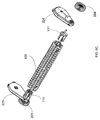
- Figure 1 illustrates a cleaning brush 100 according to an embodiment of the invention.
- Figure 2 is a cross sectional view of a cleaning brush 100 according to an embodiment of the invention.
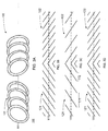
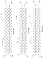
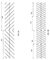
- Figures 3A-3D, 4A-4C and 5A are front views of cleaning brush 100 according to various embodiments of the invention.
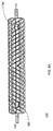
- Figure 6A illustrates a cleaning brush 100 according to an embodiment of the invention.
- the cleaning brush 100 includes:
- figure 1 illustrates fins that form right handed and left handed fins 120 and 130 - these fins can be replaced by spaced apart ring shaped fins that surround the central portion 160.
- the cleaning brush 100 also includes (a) first protuberances 140 that are oriented in relation to the right handed fin 120 and (b) second protuberances 150 that are oriented in relation to the left handed continuous threaded fin 130.
- Figures 3A-3D illustrate a cleaning brush 100 that includes (a) first fins 121 that have a positive slope in relation to the longitudinal axis 111 and surround a first section 102 of central portion 160 and (b) second fins 122 that have a negative slope in relation to the longitudinal axis 111 and surround a second section of the central portion 160.
- Figure 1 also illustrates (a) first protuberances 140 that are oriented in relation to the first fins and (b) second protuberances 150 that are oriented in relation to the second fins.
- any reference to the right handed and left fins 120 and 130 is applicable mutatis mutandis to the first and second ring shaped fins 121 and 122 of figures 3B-3D .
- the central portion 160 can have a cylindrical shape and can be separate from or integrated with at least one component out of the right handed fin 120, the left handed fin 130, the first protuberances 140 and the second protuberances 150.
- Figures 1 , 3B, 3C,3D 4A, 4B, 4C , 6A , 8 , 9 and 10 illustrate first and second sections that are of equal length - each equals one half of the length of the cleaning brush. It is noted that the first and second portions may differ from each other by length (see, figure 5A ). It is also noted that other embodiments may exist where the length of each one of the first and second sections may be shorter than one half of the length of the cleaning brush 100 (see, figure 5B ).
- Figures 1, 4A and 7-10 illustrate the first protuberances 140 and the second protuberances 150 as being identical to each other, being arranges in rows that are parallel to the longitudinal axis 111 and as extending radially from the central portion 160. It is noted that the shape, size, orientation and arrangement of these first and second protuberances 140 and 150 may differ from those illustrated in figures 1, 4A and 7-10 .
- first and second protuberances 140 and 150 may be arranged in a manner that is not parallel (is oriented) to the longitudinal axis 111 - as illustrated in figure 4B .
- first and second protuberances 140 and 150 may be arranged in a manner that is parallel to the longitudinal axis 111 and some of the first and second protuberances 140 and 150 may be arranged in a manner that is not parallel (is oriented) to the longitudinal axis 111 - as illustrated in figure 4C .
- two or more protuberances out of the first and second protuberances 140 and 150 may differ from each other by shape, size and/or orientation.
- the cleaning brush 100 is illustrated in figures 1, 3A, 3B, 3C, 3D, 4A, 4B, 4C and7-10 as including an axis of symmetry (denoted 103 in figure 1 ) wherein the first and second sections 101 and 102 are mutually symmetrical about this axis, the first protuberances 140 and the second protuberances 150 are symmetrical about this axis and the right handed fin 120 and the left handed fin 130 are symmetrical about this axis.
- Alternatively - axis 103 is not a symmetry axis and at least one component (first section 101, right handed fin 120 and first protuberances 140) on side of the axis differs from another component (second section 102, left handed fin 130, and the second protuberances 150) located at another side of the axis.
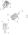
- Figure 6D illustrates an interface 111 of a cleaning brush 100 according to an embodiment of the invention.
- Figures 6C and 6D illustrate interfaces 111 and 111' of a cleaning brush 100, a cleaning brush 100 and additional components 201, 204, 221 and 224 according to an embodiment of the invention.
- the cleaning brush 100 has an interface (such as interfaces 111 of figures 6B-6D ) - one interface at each side of the cleaning brush for detachably connecting the cleaning brush 100 to the pool cleaning apparatus.
- the cleaning brush may have at least one opening (openings 190 of figure 6A ) that allows access to interface 111 and especially to a snap action lock 112 of interface 111 that facilitate a detachment of the cleaning brush 100 from the pool cleaning apparatus by pressing the snap action lock 112.
- the snap action lock 102 can include a movable element that can be moved from being at a first position in which it prevents the cleaning brush 110 from being removed from the pool cleaning apparatus and a second position in which is allows the detachment of the cleaning brush from the pool cleaning apparatus.
- the snap action lock 112 can be moved vertically or radially (or in any other manner) between these positions. For example - when in the first position the snap action lock 102 can extend through the opening 190 or another opening while when in the second position the snap action lock 102 can be pushed away from that opening.
- the interface 111 is shown as including an axis 110 that may be rotated by a movement module (such as movement modules 221, 222, 223 and 224), a main body 113 and the snap action lock 112.
- the interface can be released from the cleaning brush by unscrewing screws that connect the interface 111 to the pool cleaning apparatus- the openings are wide enough to allow inserting a screwdriver there-through.
- Figure 5B illustrates a cleaning brush 100 that includes four sections 101 (not shown), 102, 103 (symmetry line is not shown), and 104 - two right handed fins 101 and 103 as well as two left handed fins 102 and 104.
- This cleaning brush 100 may also have first and second protuberances such as those illustrated in any of the previous figures. That cleaning brush can have ring shaped fins instead of such right and left handed fins.
- the cleaning brush can have multiple right handed fins and multiple left handed fins.
- the cleaning brush can have a combination of one or more right handed fins and ring shaped fins. Additionally or alternatively, the cleaning brush can include a combination of one or more left handed fins and ring shaped fins.
- the distance between different windings of a right handed fin may be the same.
- a first pair of windings of the right handed fin may be distant from each other by a distance between a second pair of windings of the right handed fin or a distance between a third pair of windings of a left handed fin of the same cleaning brush.
- the distance between different windings of a left handed fin may be the same.
- a first pair of windings of the left handed fin may be distant from each other by a distance between a second pair of windings of the left handed fin or a distance between a third pair of windings of a right handed fin of the same cleaning brush.
- the distance between different first ring shaped fins may be the same.
- the distance between different second ring shaped fins may be the same.
- a first pair of first ring shaped fins may be distant from each other by a distance that differs from the distance between a second pair of first ring shaped fins or a distance between a third pair of second ring shaped fins.
- An example of differences between inter-ring shaped fins is shown in figure 3C - see, for example, distance 171 is bigger than distance 172. While in figure 3C the distances between ring shaped fins increases towards the edges of the cleaning brush - these distances can decrease towards the edges of the cleaning brush, or change in a non-monotonic manner.
- FIG. 1 and 7-10 illustrate the right handed fin 120 as having windings that are parallel to each other and the left handed fin 130 as having windings that are parallel to each other.
- at least one of the winding of a certain fin can be non-parallel to another winding of that certain fin. The same applies to ring shaped fins.
- figure 3B shows first rings 121 of positive slope and second rings 122 of negative slope wherein an absolute value of the positive slope substantially equals to an absolute value of the negative slope. It is noted that the absolute value of the positive slope may differ from the absolute value of the negative slope.
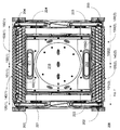
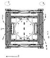
- Figure 7 illustrates a bottom view of a pool cleaning apparatus 200 according to an embodiment of the invention.
- the bottom panel 210 of the pool cleaning apparatus 200 has two inlets 211 and 212 - located at the center of the pool cleaning apparatus 200.
- Figure 7 also shows four side brushes 201-204.
- a combination of any of the cleaning brushes illustrated in any previous figures can be detachably connected to other elements of a pool cleaning apparatus.
- the pool cleaning apparatus can include one or more cleaning brushes as illustrated in any of the previous figures and any other shaped and sized cleaning brush known in the art.
- FIG 7 - pool cleaning apparatus 200 includes first and second cleaning brushes 100(1) and 100(2) - each is identical to the cleaning brush 100 of figure 1 .
- the first cleaning brush 100(1) includes a first central portion (such as central portion 160 of figure 6b ) that has a first longitudinal axis (such as longitudinal axis 111 of figure 2 ); a first right handed fin 120(1) that surrounds a first section 101(1) of the first central portion ; and a first left handed fin 130(1) that surrounds a second section 102(1) of the first central portion 160.
- a first central portion such as central portion 160 of figure 6b
- first longitudinal axis such as longitudinal axis 111 of figure 2
- first right handed fin 120(1) that surrounds a first section 101(1) of the first central portion
- a first left handed fin 130(1) that surrounds a second section 102(1) of the first central portion 160.
- Figure 7 also shows the first cleaning brush 101(1) as including first protuberances 140(1) that are oriented in relation to the first right handed fin 120(1) and second protuberances 150(1) that are oriented in relation to the first left handed fin 130(1).
- the second cleaning brush 101(2) includes a second central portion 160 (such as central portion 160 of figure 1 ) that has a second longitudinal axis (such as longitudinal axis 111 of figure 2 ); a second right handed fin 120(2) that surrounds a first section 101(2) of the second central portion ; and a second left handed fin 130(2) that surrounds a second section 102(2) of the second central portion 160.
- a second central portion 160 such as central portion 160 of figure 1
- the second longitudinal axis such as longitudinal axis 111 of figure 2
- a second right handed fin 120(2) that surrounds a first section 101(2) of the second central portion
- a second left handed fin 130(2) that surrounds a second section 102(2) of the second central portion 160.
- Figure 7 also shows the second cleaning brush 100(2) as including third protuberances 140(2) that are oriented in relation to the second right handed fin 120(2) and forth protuberances 150(2) that are oriented in relation to the second left handed fin 130(2).
- the pool cleaning apparatus has a movement module (illustrated by transmission mechanism 221, 222, 223 and 224) that is arranged to rotate the first and second cleaning brushes 100(1) and 100(2) in synchronicity to each other or independently from each other.
- a movement module illustrated by transmission mechanism 221, 222, 223 and 224.
- Figure 8 illustrates a bottom view of a pool cleaning apparatus 200 when propagating along a first direction 303 in which a first cleaning brush 100(1) is a front cleaning brush according to an embodiment of the invention.
- Figure 9 illustrates a bottom view of a pool cleaning apparatus 200 when propagating along a second direction 304 that is opposite to the first direction 303 in which a first cleaning brush 100(1) is a rear cleaning brush, according to an embodiment of the invention.
- Figures 8 and 9 illustrates the first and second cleaning brushes 100(1) and 100(2) as being rotated at a same rotational direction (counterclockwise 305 in figure 8 and clockwise 306 in figure 9 ) about their longitudinal axes.
- the movement module shown as being arranged to rotate the first and second cleaning brushes 100(1) and 100(2) at the same rotational direction about their longitudinal axes thereby causing a front cleaning brush (first cleaning brush 100(1)) to direct debris (dashed arrows 301) towards a fluid inlet 211 of the pool cleaning apparatus 200 and causing a rear cleaning brush (second cleaning brush 100(2)) to direct debris (dashed arrows 302) away from a center of the pool cleaning apparatus 212.
- the movement module shown as being arranged to rotate the first and second cleaning brushes 100(1) and 100(2) at the same rotational direction about their longitudinal axes thereby causing the front cleaning brush (second cleaning brush 100(2)) to direct debris (dashed arrows 302) towards a fluid inlet 212 of the pool cleaning apparatus 200 and causing a rear cleaning brush (first cleaning brush 100(1)) to direct debris (dashed arrows 301) away from a center of the pool cleaning apparatus 211.
- Figure 10 illustrates a pool cleaning apparatus 200 that includes two cleaning brushes 100(1) and 100(2) that are identical to the cleaning brushes of figure 3B .
- the pool cleaning apparatus may include at least one intermediate brush positioned between the first and second cleaning brushed 100(1) and 100(2) - such as intermediate brush 100(3) of figure 11 .
- any arrangement of components to achieve the same functionality is effectively “associated” such that the desired functionality is achieved.
- any two components herein combined to achieve a particular functionality may be seen as “associated with” each other such that the desired functionality is achieved, irrespective of architectures or intermedial components.
- any two components so associated can also be viewed as being “operably connected,” or “operably coupled,” to each other to achieve the desired functionality.
- any reference signs placed between parentheses shall not be construed as limiting the claim.
- the word 'comprising' does not exclude the presence of other elements or steps then those listed in a claim.
- the terms "a” or "an,” as used herein, are defined as one or more than one.
Landscapes
- Engineering & Computer Science (AREA)
- Architecture (AREA)
- Civil Engineering (AREA)
- Structural Engineering (AREA)
- Nozzles For Electric Vacuum Cleaners (AREA)
- Brushes (AREA)
Claims (15)
- Brosse de nettoyage (100) pour un appareil de nettoyage de piscine, la brosse de nettoyage comprend:une partie centrale (160) qui présente un axe longitudinal (111);dans laquelle la brosse de nettoyage est caractérisée en ce qu'elle comprend:une ailette de droite (120) qui entoure une première section (101) de la partie centrale;une ailette de gauche (130) qui entoure une deuxième section (102) de la partie centrale;des premières protubérances (140) qui sont orientées par rapport à l'ailette de droite; et des deuxièmes protubérances (150) qui sont orientées par rapport à l'ailette de gauche.
- Brosse de nettoyage selon la revendication 1, dans laquelle les première et deuxième sections (101, 102) sont de longueur égale.
- Brosse de nettoyage selon la revendication 1, dans laquelle les première et deuxième protubérances (140,150) sont sensiblement parallèles à l'axe longitudinal.
- Brosse de nettoyage selon la revendication 1, dans laquelle les ailettes de droite et les ailettes de gauche (120, 130) sont mutuellement symétriques autour d'un axe imaginaire qui sépare virtuellement les première et deuxième sections.
- Brosse de nettoyage selon la revendication 1, comprenant un adaptateur pour connecter de façon amovible la brosse de nettoyage à l'appareil de nettoyage de piscine; et au moins une ouverture qui facilite le détachement de la brosse de nettoyage de l'appareil de nettoyage de piscine par la manipulation de l'adaptateur.
- Brosse de nettoyage selon la revendication 5, dans laquelle l'adaptateur comprend un verrou à action rapide qui est accessible à travers la au moins une ouverture.
- Brosse de nettoyage selon la revendication 1, dans laquelle les ailettes de gauche, les ailettes de droite, et les première et deuxième protubérances sont surmoulées à la partie centrale.
- Brosse de nettoyage selon la revendication 1, dans laquelle chacune des ailettes de droite et gauche définit une trajectoire hélicoïdale.
- Brosse de nettoyage selon la revendication 1, comprenant plusieurs ailettes de droite et plusieurs ailettes de gauche.
- Brosse de nettoyage pour un appareil de nettoyage de piscine, la brosse de nettoyage comprend:une partie centrale (160) qui présente un axe longitudinal (111);dans laquelle la brosse de nettoyage est caractérisée en ce qu'elle comprend;des premières ailettes (120, 121) qui présentent une pente positive par rapport à l'axe longitudinal etentourent une première section (101) de la partie centrale;des deuxièmes ailettes (122, 130) qui présentent une pente négative par rapport à l'axe longitudinal et entourent une deuxième section (102) de la partie centrale;des premières protubérances (140) qui sont orientées par rapport aux premières ailettes; et des deuxièmes protubérances (150) qui sont orientées par rapport aux deuxièmes ailettes.
- Brosse de nettoyage selon la revendication 10, dans laquelle chacun des premier et deuxième groupes d'ailettes comprend des ailettes en forme d'anneaux multiples qui sont espacés les uns des autres.
- Brosse de nettoyage selon la revendication 10, dans laquelle les première et deuxième sections (101, 102) sont égales l'une à l'autre
- Brosse de nettoyage selon la revendication 10, dans laquelle une valeur absolue de la pente positive est sensiblement égale à une valeur absolue de la pente négative.
- Brosse de nettoyage selon la revendication 10, dans laquelle les première et deuxième protubérances (150) sont sensiblement parallèles à l'axe longitudinal (111).
- Brosse de nettoyage selon la revendication 10, dans laquelle les première et deuxième protubérances (150) ne sont pas parallèles les unes aux autres.
Applications Claiming Priority (1)
| Application Number | Priority Date | Filing Date | Title |
|---|---|---|---|
| IL226976A IL226976B (en) | 2013-06-16 | 2013-06-16 | Cleaning brush for a pool cleaning apparatus |
Publications (2)
| Publication Number | Publication Date |
|---|---|
| EP2813645A1 EP2813645A1 (fr) | 2014-12-17 |
| EP2813645B1 true EP2813645B1 (fr) | 2016-05-25 |
Family
ID=50731944
Family Applications (1)
| Application Number | Title | Priority Date | Filing Date |
|---|---|---|---|
| EP14168359.9A Active EP2813645B1 (fr) | 2013-06-16 | 2014-05-14 | Brosse de nettoyage pour appareil de nettoyage de piscine |
Country Status (4)
| Country | Link |
|---|---|
| US (1) | US9758978B2 (fr) |
| EP (1) | EP2813645B1 (fr) |
| ES (1) | ES2586617T3 (fr) |
| IL (1) | IL226976B (fr) |
Families Citing this family (5)
| Publication number | Priority date | Publication date | Assignee | Title |
|---|---|---|---|---|
| USD757446S1 (en) * | 2014-02-10 | 2016-05-31 | Nancy A. Ewert | Pool skimmer brush attachment |
| ES2897978T3 (es) | 2016-09-13 | 2022-03-03 | Maytronics Ltd | Robots de limpieza de piscinas maestros y esclavos |
| USD841268S1 (en) * | 2017-03-18 | 2019-02-19 | AI Incorporated | Rotating brush |
| CN210239261U (zh) * | 2019-05-21 | 2020-04-03 | 明达实业(厦门)有限公司 | 一种水池清洁器的轮刷固定结构 |
| AU2020284603B2 (en) | 2019-05-29 | 2025-01-23 | Zodiac Pool Care Europe | Brush assemblies principally for automatic swimming pool cleaners |
Family Cites Families (12)
| Publication number | Priority date | Publication date | Assignee | Title |
|---|---|---|---|---|
| US1815084A (en) * | 1929-01-02 | 1931-07-21 | Hoover Co | Suction cleaner agitator |
| US1894361A (en) * | 1929-11-22 | 1933-01-17 | Hoover Co | Suction cleaner agitator |
| US1888339A (en) * | 1931-01-14 | 1932-11-22 | Hoover Co | Suction cleaner |
| US2334714A (en) * | 1941-11-21 | 1943-11-23 | United Shoe Machinery Corp | Brushing machine |
| US3139641A (en) * | 1961-06-22 | 1964-07-07 | Power Brushes Inc | Cylindrical brush construction |
| US4209873A (en) * | 1978-06-02 | 1980-07-01 | National Union Electric Corporation | Brush-beater for a vacuum cleaner and method for making the same |
| US5337434A (en) | 1993-04-12 | 1994-08-16 | Aqua Products, Inc. | Directional control means for robotic swimming pool cleaners |
| US6003186A (en) | 1997-02-18 | 1999-12-21 | Tennant Company | Cylindrical brush for a sweeping machine |
| DE102004042786A1 (de) | 2004-09-03 | 2006-03-09 | Simon Schmeiler | Vorrichtung zur vollautomatischen Reinigung eines Pools mit selbständiger Schmutzerkennung, auswechselbaren und zusätzlichen Walzen |
| CN101280634B (zh) | 2007-04-03 | 2012-01-25 | 卓景顾问有限公司 | 一种水池清洁机的滚筒 |
| KR101133091B1 (ko) | 2010-08-20 | 2012-04-04 | 재단법인 포항지능로봇연구소 | 청소로봇, 수중 청소장치 및 수중 청소방법 |
| USD682497S1 (en) * | 2010-12-21 | 2013-05-14 | Entegris, Inc. | Substrate cleaning brush |
-
2013
- 2013-06-16 IL IL226976A patent/IL226976B/en active IP Right Grant
-
2014
- 2014-03-31 US US14/230,032 patent/US9758978B2/en active Active
- 2014-05-14 EP EP14168359.9A patent/EP2813645B1/fr active Active
- 2014-05-14 ES ES14168359.9T patent/ES2586617T3/es active Active
Also Published As
| Publication number | Publication date |
|---|---|
| ES2586617T3 (es) | 2016-10-17 |
| IL226976B (en) | 2018-01-31 |
| US9758978B2 (en) | 2017-09-12 |
| US20140366297A1 (en) | 2014-12-18 |
| EP2813645A1 (fr) | 2014-12-17 |
Similar Documents
| Publication | Publication Date | Title |
|---|---|---|
| US9758978B2 (en) | Cleaning brush for a pool cleaning apparatus | |
| US9677295B2 (en) | Scrubber assembly for a pool cleaner | |
| US11124983B2 (en) | Automatic pool cleaner | |
| US9809991B2 (en) | Pool cleaner with multi-stage venturi vacuum assembly | |
| KR102504105B1 (ko) | 진공 청소기 | |
| US8990990B2 (en) | Pool cleaner with hydraulic timer assembly | |
| TWI653023B (zh) | 清掃機 | |
| EP3926126B1 (fr) | Robot de nettoyage de piscine | |
| CN106123281A (zh) | 一种空调过滤网自动除尘机构及空调器 | |
| CN107762195B (zh) | 一种驱动换向机构以及水池清洁器 | |
| WO2014151086A2 (fr) | Nettoyeur de piscines à haute pression doté d'un mécanisme de décompte automatique du temps | |
| US8381344B1 (en) | Hard water deposit removal system | |
| JP2026501624A (ja) | 清掃ブラシ及び自動清掃機器 | |
| CN222885338U (zh) | 自动清洁设备 | |
| US20080244842A1 (en) | Motorised Pool-Cleaning Device Comprising Freewheel Rotary Movement Means | |
| TWM680263U (zh) | 邊刷組件和清潔設備 | |
| KR20250130818A (ko) | 청소 모듈 및 청소 장치 | |
| CN101301184A (zh) | 转动式真空吸尘器吸嘴 | |
| CN218991064U (zh) | 一种带毛刷的泳池清洁机器人 | |
| CN224093060U (zh) | 一种清洁滚刷和水下清洁机器人 | |
| CN222716586U (zh) | 一种泳池清洁器 | |
| US11795718B2 (en) | Brush assemblies principally for automatic swimming pool cleaners | |
| KR20250123900A (ko) | 청소 모듈 및 청소 장치 | |
| CN116998956A (zh) | 自动清洁设备 | |
| JP2026506318A (ja) | 清掃ブラシ及び自動清掃機器 |
Legal Events
| Date | Code | Title | Description |
|---|---|---|---|
| 17P | Request for examination filed |
Effective date: 20140514 |
|
| AK | Designated contracting states |
Kind code of ref document: A1 Designated state(s): AL AT BE BG CH CY CZ DE DK EE ES FI FR GB GR HR HU IE IS IT LI LT LU LV MC MK MT NL NO PL PT RO RS SE SI SK SM TR |
|
| AX | Request for extension of the european patent |
Extension state: BA ME |
|
| PUAI | Public reference made under article 153(3) epc to a published international application that has entered the european phase |
Free format text: ORIGINAL CODE: 0009012 |
|
| R17P | Request for examination filed (corrected) |
Effective date: 20150617 |
|
| RBV | Designated contracting states (corrected) |
Designated state(s): AL AT BE BG CH CY CZ DE DK EE ES FI FR GB GR HR HU IE IS IT LI LT LU LV MC MK MT NL NO PL PT RO RS SE SI SK SM TR |
|
| RIC1 | Information provided on ipc code assigned before grant |
Ipc: E04H 4/16 20060101AFI20151023BHEP |
|
| GRAP | Despatch of communication of intention to grant a patent |
Free format text: ORIGINAL CODE: EPIDOSNIGR1 |
|
| INTG | Intention to grant announced |
Effective date: 20151211 |
|
| GRAS | Grant fee paid |
Free format text: ORIGINAL CODE: EPIDOSNIGR3 |
|
| GRAA | (expected) grant |
Free format text: ORIGINAL CODE: 0009210 |
|
| AK | Designated contracting states |
Kind code of ref document: B1 Designated state(s): AL AT BE BG CH CY CZ DE DK EE ES FI FR GB GR HR HU IE IS IT LI LT LU LV MC MK MT NL NO PL PT RO RS SE SI SK SM TR |
|
| REG | Reference to a national code |
Ref country code: GB Ref legal event code: FG4D |
|
| REG | Reference to a national code |
Ref country code: CH Ref legal event code: EP |
|
| REG | Reference to a national code |
Ref country code: IE Ref legal event code: FG4D Ref country code: AT Ref legal event code: REF Ref document number: 802472 Country of ref document: AT Kind code of ref document: T Effective date: 20160615 |
|
| REG | Reference to a national code |
Ref country code: DE Ref legal event code: R096 Ref document number: 602014002057 Country of ref document: DE |
|
| REG | Reference to a national code |
Ref country code: LT Ref legal event code: MG4D |
|
| REG | Reference to a national code |
Ref country code: NL Ref legal event code: MP Effective date: 20160525 |
|
| REG | Reference to a national code |
Ref country code: ES Ref legal event code: FG2A Ref document number: 2586617 Country of ref document: ES Kind code of ref document: T3 Effective date: 20161017 |
|
| PG25 | Lapsed in a contracting state [announced via postgrant information from national office to epo] |
Ref country code: FI Free format text: LAPSE BECAUSE OF FAILURE TO SUBMIT A TRANSLATION OF THE DESCRIPTION OR TO PAY THE FEE WITHIN THE PRESCRIBED TIME-LIMIT Effective date: 20160525 Ref country code: LT Free format text: LAPSE BECAUSE OF FAILURE TO SUBMIT A TRANSLATION OF THE DESCRIPTION OR TO PAY THE FEE WITHIN THE PRESCRIBED TIME-LIMIT Effective date: 20160525 Ref country code: NO Free format text: LAPSE BECAUSE OF FAILURE TO SUBMIT A TRANSLATION OF THE DESCRIPTION OR TO PAY THE FEE WITHIN THE PRESCRIBED TIME-LIMIT Effective date: 20160825 Ref country code: NL Free format text: LAPSE BECAUSE OF FAILURE TO SUBMIT A TRANSLATION OF THE DESCRIPTION OR TO PAY THE FEE WITHIN THE PRESCRIBED TIME-LIMIT Effective date: 20160525 |
|
| PG25 | Lapsed in a contracting state [announced via postgrant information from national office to epo] |
Ref country code: RS Free format text: LAPSE BECAUSE OF FAILURE TO SUBMIT A TRANSLATION OF THE DESCRIPTION OR TO PAY THE FEE WITHIN THE PRESCRIBED TIME-LIMIT Effective date: 20160525 Ref country code: GR Free format text: LAPSE BECAUSE OF FAILURE TO SUBMIT A TRANSLATION OF THE DESCRIPTION OR TO PAY THE FEE WITHIN THE PRESCRIBED TIME-LIMIT Effective date: 20160826 Ref country code: SE Free format text: LAPSE BECAUSE OF FAILURE TO SUBMIT A TRANSLATION OF THE DESCRIPTION OR TO PAY THE FEE WITHIN THE PRESCRIBED TIME-LIMIT Effective date: 20160525 Ref country code: PT Free format text: LAPSE BECAUSE OF FAILURE TO SUBMIT A TRANSLATION OF THE DESCRIPTION OR TO PAY THE FEE WITHIN THE PRESCRIBED TIME-LIMIT Effective date: 20160926 Ref country code: LV Free format text: LAPSE BECAUSE OF FAILURE TO SUBMIT A TRANSLATION OF THE DESCRIPTION OR TO PAY THE FEE WITHIN THE PRESCRIBED TIME-LIMIT Effective date: 20160525 |
|
| PG25 | Lapsed in a contracting state [announced via postgrant information from national office to epo] |
Ref country code: EE Free format text: LAPSE BECAUSE OF FAILURE TO SUBMIT A TRANSLATION OF THE DESCRIPTION OR TO PAY THE FEE WITHIN THE PRESCRIBED TIME-LIMIT Effective date: 20160525 Ref country code: CZ Free format text: LAPSE BECAUSE OF FAILURE TO SUBMIT A TRANSLATION OF THE DESCRIPTION OR TO PAY THE FEE WITHIN THE PRESCRIBED TIME-LIMIT Effective date: 20160525 Ref country code: DK Free format text: LAPSE BECAUSE OF FAILURE TO SUBMIT A TRANSLATION OF THE DESCRIPTION OR TO PAY THE FEE WITHIN THE PRESCRIBED TIME-LIMIT Effective date: 20160525 Ref country code: RO Free format text: LAPSE BECAUSE OF FAILURE TO SUBMIT A TRANSLATION OF THE DESCRIPTION OR TO PAY THE FEE WITHIN THE PRESCRIBED TIME-LIMIT Effective date: 20160525 Ref country code: SK Free format text: LAPSE BECAUSE OF FAILURE TO SUBMIT A TRANSLATION OF THE DESCRIPTION OR TO PAY THE FEE WITHIN THE PRESCRIBED TIME-LIMIT Effective date: 20160525 |
|
| PG25 | Lapsed in a contracting state [announced via postgrant information from national office to epo] |
Ref country code: BE Free format text: LAPSE BECAUSE OF FAILURE TO SUBMIT A TRANSLATION OF THE DESCRIPTION OR TO PAY THE FEE WITHIN THE PRESCRIBED TIME-LIMIT Effective date: 20160525 Ref country code: SM Free format text: LAPSE BECAUSE OF FAILURE TO SUBMIT A TRANSLATION OF THE DESCRIPTION OR TO PAY THE FEE WITHIN THE PRESCRIBED TIME-LIMIT Effective date: 20160525 Ref country code: PL Free format text: LAPSE BECAUSE OF FAILURE TO SUBMIT A TRANSLATION OF THE DESCRIPTION OR TO PAY THE FEE WITHIN THE PRESCRIBED TIME-LIMIT Effective date: 20160525 |
|
| REG | Reference to a national code |
Ref country code: DE Ref legal event code: R097 Ref document number: 602014002057 Country of ref document: DE |
|
| PLBE | No opposition filed within time limit |
Free format text: ORIGINAL CODE: 0009261 |
|
| STAA | Information on the status of an ep patent application or granted ep patent |
Free format text: STATUS: NO OPPOSITION FILED WITHIN TIME LIMIT |
|
| 26N | No opposition filed |
Effective date: 20170228 |
|
| REG | Reference to a national code |
Ref country code: FR Ref legal event code: PLFP Year of fee payment: 4 |
|
| PG25 | Lapsed in a contracting state [announced via postgrant information from national office to epo] |
Ref country code: SI Free format text: LAPSE BECAUSE OF FAILURE TO SUBMIT A TRANSLATION OF THE DESCRIPTION OR TO PAY THE FEE WITHIN THE PRESCRIBED TIME-LIMIT Effective date: 20160525 |
|
| PG25 | Lapsed in a contracting state [announced via postgrant information from national office to epo] |
Ref country code: LU Free format text: LAPSE BECAUSE OF NON-PAYMENT OF DUE FEES Effective date: 20170531 |
|
| PG25 | Lapsed in a contracting state [announced via postgrant information from national office to epo] |
Ref country code: MC Free format text: LAPSE BECAUSE OF FAILURE TO SUBMIT A TRANSLATION OF THE DESCRIPTION OR TO PAY THE FEE WITHIN THE PRESCRIBED TIME-LIMIT Effective date: 20160525 |
|
| REG | Reference to a national code |
Ref country code: IE Ref legal event code: MM4A |
|
| PG25 | Lapsed in a contracting state [announced via postgrant information from national office to epo] |
Ref country code: LU Free format text: LAPSE BECAUSE OF NON-PAYMENT OF DUE FEES Effective date: 20170514 |
|
| PG25 | Lapsed in a contracting state [announced via postgrant information from national office to epo] |
Ref country code: IE Free format text: LAPSE BECAUSE OF NON-PAYMENT OF DUE FEES Effective date: 20170514 |
|
| REG | Reference to a national code |
Ref country code: FR Ref legal event code: PLFP Year of fee payment: 5 |
|
| PG25 | Lapsed in a contracting state [announced via postgrant information from national office to epo] |
Ref country code: MT Free format text: LAPSE BECAUSE OF NON-PAYMENT OF DUE FEES Effective date: 20170514 |
|
| PG25 | Lapsed in a contracting state [announced via postgrant information from national office to epo] |
Ref country code: AL Free format text: LAPSE BECAUSE OF FAILURE TO SUBMIT A TRANSLATION OF THE DESCRIPTION OR TO PAY THE FEE WITHIN THE PRESCRIBED TIME-LIMIT Effective date: 20160525 |
|
| GBPC | Gb: european patent ceased through non-payment of renewal fee |
Effective date: 20180514 |
|
| REG | Reference to a national code |
Ref country code: AT Ref legal event code: UEP Ref document number: 802472 Country of ref document: AT Kind code of ref document: T Effective date: 20160525 |
|
| PG25 | Lapsed in a contracting state [announced via postgrant information from national office to epo] |
Ref country code: GB Free format text: LAPSE BECAUSE OF NON-PAYMENT OF DUE FEES Effective date: 20180514 |
|
| PG25 | Lapsed in a contracting state [announced via postgrant information from national office to epo] |
Ref country code: HU Free format text: LAPSE BECAUSE OF FAILURE TO SUBMIT A TRANSLATION OF THE DESCRIPTION OR TO PAY THE FEE WITHIN THE PRESCRIBED TIME-LIMIT; INVALID AB INITIO Effective date: 20140514 |
|
| PG25 | Lapsed in a contracting state [announced via postgrant information from national office to epo] |
Ref country code: BG Free format text: LAPSE BECAUSE OF FAILURE TO SUBMIT A TRANSLATION OF THE DESCRIPTION OR TO PAY THE FEE WITHIN THE PRESCRIBED TIME-LIMIT Effective date: 20160525 |
|
| PG25 | Lapsed in a contracting state [announced via postgrant information from national office to epo] |
Ref country code: CY Free format text: LAPSE BECAUSE OF FAILURE TO SUBMIT A TRANSLATION OF THE DESCRIPTION OR TO PAY THE FEE WITHIN THE PRESCRIBED TIME-LIMIT Effective date: 20160525 |
|
| PG25 | Lapsed in a contracting state [announced via postgrant information from national office to epo] |
Ref country code: MK Free format text: LAPSE BECAUSE OF FAILURE TO SUBMIT A TRANSLATION OF THE DESCRIPTION OR TO PAY THE FEE WITHIN THE PRESCRIBED TIME-LIMIT Effective date: 20160525 |
|
| PG25 | Lapsed in a contracting state [announced via postgrant information from national office to epo] |
Ref country code: TR Free format text: LAPSE BECAUSE OF FAILURE TO SUBMIT A TRANSLATION OF THE DESCRIPTION OR TO PAY THE FEE WITHIN THE PRESCRIBED TIME-LIMIT Effective date: 20160525 |
|
| PG25 | Lapsed in a contracting state [announced via postgrant information from national office to epo] |
Ref country code: HR Free format text: LAPSE BECAUSE OF FAILURE TO SUBMIT A TRANSLATION OF THE DESCRIPTION OR TO PAY THE FEE WITHIN THE PRESCRIBED TIME-LIMIT Effective date: 20160525 |
|
| PG25 | Lapsed in a contracting state [announced via postgrant information from national office to epo] |
Ref country code: IS Free format text: LAPSE BECAUSE OF FAILURE TO SUBMIT A TRANSLATION OF THE DESCRIPTION OR TO PAY THE FEE WITHIN THE PRESCRIBED TIME-LIMIT Effective date: 20160925 |
|
| PGFP | Annual fee paid to national office [announced via postgrant information from national office to epo] |
Ref country code: CH Payment date: 20240602 Year of fee payment: 11 |
|
| PGFP | Annual fee paid to national office [announced via postgrant information from national office to epo] |
Ref country code: AT Payment date: 20240522 Year of fee payment: 11 |
|
| PGFP | Annual fee paid to national office [announced via postgrant information from national office to epo] |
Ref country code: DE Payment date: 20250521 Year of fee payment: 12 |
|
| PGFP | Annual fee paid to national office [announced via postgrant information from national office to epo] |
Ref country code: ES Payment date: 20250627 Year of fee payment: 12 |
|
| PGFP | Annual fee paid to national office [announced via postgrant information from national office to epo] |
Ref country code: IT Payment date: 20250527 Year of fee payment: 12 |
|
| PGFP | Annual fee paid to national office [announced via postgrant information from national office to epo] |
Ref country code: FR Payment date: 20250528 Year of fee payment: 12 |
|
| REG | Reference to a national code |
Ref country code: CH Ref legal event code: H13 Free format text: ST27 STATUS EVENT CODE: U-0-0-H10-H13 (AS PROVIDED BY THE NATIONAL OFFICE) Effective date: 20251223 |
|
| PG25 | Lapsed in a contracting state [announced via postgrant information from national office to epo] |
Ref country code: AT Free format text: LAPSE BECAUSE OF NON-PAYMENT OF DUE FEES Effective date: 20250514 |
|
| REG | Reference to a national code |
Ref country code: AT Ref legal event code: MM01 Ref document number: 802472 Country of ref document: AT Kind code of ref document: T Effective date: 20250514 |
|
| PG25 | Lapsed in a contracting state [announced via postgrant information from national office to epo] |
Ref country code: CH Free format text: LAPSE BECAUSE OF NON-PAYMENT OF DUE FEES Effective date: 20250531 |