EP2813390A1 - Armrest - Google Patents
Armrest Download PDFInfo
- Publication number
- EP2813390A1 EP2813390A1 EP12871038.1A EP12871038A EP2813390A1 EP 2813390 A1 EP2813390 A1 EP 2813390A1 EP 12871038 A EP12871038 A EP 12871038A EP 2813390 A1 EP2813390 A1 EP 2813390A1
- Authority
- EP
- European Patent Office
- Prior art keywords
- armrest
- upper face
- vehicle
- face
- reinforcement ribs
- Prior art date
- Legal status (The legal status is an assumption and is not a legal conclusion. Google has not performed a legal analysis and makes no representation as to the accuracy of the status listed.)
- Granted
Links
Images


Classifications
-
- B—PERFORMING OPERATIONS; TRANSPORTING
- B60—VEHICLES IN GENERAL
- B60R—VEHICLES, VEHICLE FITTINGS, OR VEHICLE PARTS, NOT OTHERWISE PROVIDED FOR
- B60R13/00—Elements for body-finishing, identifying, or decorating; Arrangements or adaptations for advertising purposes
- B60R13/02—Internal Trim mouldings ; Internal Ledges; Wall liners for passenger compartments; Roof liners
- B60R13/0237—Side or rear panels
- B60R13/0243—Doors
-
- B—PERFORMING OPERATIONS; TRANSPORTING
- B60—VEHICLES IN GENERAL
- B60N—SEATS SPECIALLY ADAPTED FOR VEHICLES; VEHICLE PASSENGER ACCOMMODATION NOT OTHERWISE PROVIDED FOR
- B60N2/00—Seats specially adapted for vehicles; Arrangement or mounting of seats in vehicles
- B60N2/24—Seats specially adapted for vehicles; Arrangement or mounting of seats in vehicles for particular purposes or particular vehicles
- B60N2/42—Seats specially adapted for vehicles; Arrangement or mounting of seats in vehicles for particular purposes or particular vehicles the seat constructed to protect the occupant from the effect of abnormal g-forces, e.g. crash or safety seats
- B60N2/4207—Seats specially adapted for vehicles; Arrangement or mounting of seats in vehicles for particular purposes or particular vehicles the seat constructed to protect the occupant from the effect of abnormal g-forces, e.g. crash or safety seats characterised by the direction of the g-forces
- B60N2/4235—Seats specially adapted for vehicles; Arrangement or mounting of seats in vehicles for particular purposes or particular vehicles the seat constructed to protect the occupant from the effect of abnormal g-forces, e.g. crash or safety seats characterised by the direction of the g-forces transversal
-
- B—PERFORMING OPERATIONS; TRANSPORTING
- B60—VEHICLES IN GENERAL
- B60N—SEATS SPECIALLY ADAPTED FOR VEHICLES; VEHICLE PASSENGER ACCOMMODATION NOT OTHERWISE PROVIDED FOR
- B60N2/00—Seats specially adapted for vehicles; Arrangement or mounting of seats in vehicles
- B60N2/24—Seats specially adapted for vehicles; Arrangement or mounting of seats in vehicles for particular purposes or particular vehicles
- B60N2/42—Seats specially adapted for vehicles; Arrangement or mounting of seats in vehicles for particular purposes or particular vehicles the seat constructed to protect the occupant from the effect of abnormal g-forces, e.g. crash or safety seats
- B60N2/427—Seats or parts thereof displaced during a crash
- B60N2/42709—Seats or parts thereof displaced during a crash involving residual deformation or fracture of the structure
-
- B—PERFORMING OPERATIONS; TRANSPORTING
- B60—VEHICLES IN GENERAL
- B60N—SEATS SPECIALLY ADAPTED FOR VEHICLES; VEHICLE PASSENGER ACCOMMODATION NOT OTHERWISE PROVIDED FOR
- B60N2/00—Seats specially adapted for vehicles; Arrangement or mounting of seats in vehicles
- B60N2/75—Arm-rests
- B60N2/78—Arm-rests post or panel mounted
-
- B—PERFORMING OPERATIONS; TRANSPORTING
- B60—VEHICLES IN GENERAL
- B60N—SEATS SPECIALLY ADAPTED FOR VEHICLES; VEHICLE PASSENGER ACCOMMODATION NOT OTHERWISE PROVIDED FOR
- B60N2/00—Seats specially adapted for vehicles; Arrangement or mounting of seats in vehicles
- B60N2/75—Arm-rests
- B60N2/79—Adaptations for additional use of the arm-rests
- B60N2/797—Adaptations for additional use of the arm-rests for use as electrical control means, e.g. switches
Definitions
- the present invention relates to an armrest for a vehicle passenger and for attachment to a door trim that constitutes the interior of a vehicle door.
- a door trim which is an interior member, is arranged on the vehicle cabin side of a door panel, which is an exterior member, of a vehicle door.
- An armrest for a vehicle passenger is attached to this door trim.
- the armrest needs to be high-strength in order to obtain a sense of stability when a passenger places their elbow on it.
- collision load in a collision from the side of the vehicle in a lateral collision
- the armrest to have a structure that ensures sufficient strength needed for normal situations and distributes (disperses) collision load in a lateral collision or the like.
- a fracture line that extends in the vehicle forward-rearward direction is provided in substantially the center of the armrest in the vehicle width direction. Accordingly, when pressed against the seated occupant in a vehicle lateral collision, the armrest undergoes deformation by bending at the fracture line, which is a weak portion, thus distributing the collision load exerted on the armrest and reducing the impact exerted on the passenger.
- the rigidity of the armrest can be increased by aligning multiple ribs in the vehicle forward-rearward direction on the reverse face of the armrest.
- Patent Document 1 Japanese Patent Laid-open Publication No. 2009-166521
- an object of the present invention is to provide an armrest that does not invite an upward-pointed shape or a problem in the appearance and enables both ensuring high strength and the dispersion of load.
- a representative configuration of an armrest according to the present invention is an armrest for a vehicle passenger and for attachment to a door trim that constitutes the interior of a vehicle door, the armrest including: an upper face placement of an elbow of the passenger; a side face that extends downward from an inward end, with respect to a vehicle width direction, of the upper face; a connection portion that is formed at a predetermined location at an outward end, with respect to the vehicle width direction, of the upper face, and is for connection to the door trim; and a reinforcement rib that extends downward from a reverse side of the upper face between the connection portion and the side face, wherein a notch having a height such that a vertex thereof does not reach the upper face is formed in the reinforcement rib.
- the reinforcement rib is provided in the vicinity of the connection portion, which is stronger than other portions due to being connected to the door trim. For this reason, the support strength of the reinforcement rib can be increased, and the load of a placed elbow exerted on the armrest can be received by the reinforcement rib and the connection portion, that is to say by the door trim as a whole, thus making it possible to improve the load bearing characteristics of the armrest and to suppress problems such as rattling when the elbow is placed. Also, since the reinforcement rib is supported to the door trim via the connection portion, the load of a placed elbow exerted on the armrest can be efficiently transmitted to the door trim via the connection portion.
- a notch having a height such that the vertex thereof does not reach the back face of the upper face is formed in the reinforcement rib.
- This notch serves a weak portion (portion with a low strength) in the reinforcement rib, and collision load (compression load) exerted on the armrest in a lateral collision is concentrated at the vertex of the notch. Fractures thus form between the back face of the upper face and the vertex of the notch due to the concentrated collision load, and the collision load is dispersed.
- the notch has a height such that the vertex thereof does not reach the back face of the upper face, that is to say since a portion of the reinforcement rib remains between the back face of the upper face and the vertex of the notch, fractures form only in the remaining reinforcement rib portion, and the upper face of the armrest does not become a broken face.
- This makes it possible to favorably disperse the collision load and reduce the amount of damage to the passenger.
- the load of a placed elbow that is normally exerted can be absorbed by the portion of the reinforcement rib that remains between the back face of the upper face and the vertex of the notch. This makes it possible to suppress a design problem such as a poor appearance caused by a fracture line formed in the armrest as in conventional technology.
- a plurality of the reinforcement ribs may be arranged side by side in the vehicle forward-rearward direction on the armrest, and the vertices of the notches formed in the plurality of reinforcement ribs may be arranged at different positions in the vehicle width direction. According to this, the positions of the vertices of the notches that are weak portions in the reinforcement ribs are shifted in the vehicle width direction in the vehicle forward-rearward direction of the armrest.
- the vertices of the notches formed in the plurality of reinforcement ribs may be located farther inward in the vehicle width direction the closer the reinforcement rib is to a vehicle front side.
- the vertices of the notches are located on a line that extends from the vehicle rearward side and the outer side in the vehicle width direction to the vehicle forward side and the inner side in the vehicle width direction.
- a weak portion line is set in the upper face of the armrest. This weak portion line extends toward the vehicle forward side and the inner side in the vehicle width direction (corner portion) that is high-strength due to the upper face and the side face being connected.
- the upper face of the armrest is less likely to break (a broken face is less likely to form) when a high collision load is exerted in a lateral collision or the like, and it is possible to more reliably reduce the amount of damage to the passage.
- the vertices of the notches formed in the plurality of reinforcement ribs may be located closer to the upper face the closer the reinforcement rib is to a vehicle front side. According to this configuration, on the vehicle rearward side of the armrest where the passenger's elbow is placed, that is to say where the load of a placed elbow is likely to be exerted, the distance between the back face of the upper face and the vertices of the notches formed in the reinforcement rib is longer, and a larger portion of the reinforcement rib remains therebetween. This enables ensuring high strength against the load of a placed elbow in the ribs on the vehicle rearward side.
- the distance between the back face of the upper face and the vertex of the notch formed in the reinforcement rib is shorter, thus increasing the amount of deformation of the reinforcement rib and effectively alleviating collision load. This makes it possible to promote both ensuring high strength and the dispersion of load.
- the present invention enables providing an armrest that does not invite an upward-pointed shape or a problem in the appearance and enables both ensuring high strength and the dispersion of load.
- FIG. 1 is a diagram showing a door 100 that includes an armrest of the present embodiment.
- FIG. 1(a) is a side view of a vehicle cabin side of the door 100
- FIG. 1(b) is a perspective view of a door trim 104 and an armrest 140 in FIG. 1(a) .
- the door trim 104 which is an interior member, of the door 100 of a vehicle (not shown in its entirety) is arranged on the vehicle cabin side of the door panel 102, which is an exterior member.
- the door trim 104 is constituted by a board 110, which serves as its body, and various members attached thereto.
- the members attached to the board 110 include an ornament 120 that constitutes the upper portion of the side face (design face) of the door trim 104, and a pocket 130 that forms a storage space in the door 100.
- the armrest 140 for a passenger P (indicated by dashed double-dotted lines) is attached to the door trim 104.
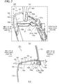
- FIG. 2 is an enlarged view of the door trim 104 in FIG. 1(b) .
- FIG. 2(a) is an enlarged perspective view of the door trim 104 in FIG. 1(b) as observed from below on the rear side of the vehicle, and
- FIG. 2(b) is a cross-sectional view taken along A-A in FIG. 2(a) . Note that the board 110 of the door trim 104 is not shown in FIG. 2(a) in order to facilitate understanding.
- the present embodiment is described taking the example of a configuration in which the armrest 140 is attached to the ornament 120 that is part of the door trim 104, there is no limitation to this, and it goes without saying that similar effects are obtained even with a configuration in which the armrest 140 is attached to the body (i.e., the board 110) of the door trim 104.
- the present embodiment is described taking the example of the case where the armrest 140 is attached to the ornament 120 (door trim 104) by welding, there is no limitation to this case either, and naturally the present invention is also applicable in the case where the armrest 140 is attached to the ornament 120 by another means such as clip attachment or screw-fastening.
- the armrest 140 of the present embodiment has an upper face 142 that serves as an elbow placement face for the passenger P, and a side face 144 that extends downward from the inner end portion of the upper face 142 with respect to the vehicle width direction.
- the armrest 140 is substantially shaped as an "L" formed by the upper face 142 and the side face 144 when viewed in cross-section in the vehicle width direction.
- a connection portion 146a for connecting the armrest 140 to the door trim 104 (the ornament 120 in the present embodiment) is provided at a predetermined location in an outer end portion of the upper face 142 of the armrest 140 with respect the vehicle width direction.
- connection portion 146a of the present embodiment is constituted by a boss seating face 147a that is provided so as to extend downward in the vicinity of the outward end, with respect to the vehicle width direction, of the upper face 142 of the armrest 140, and a welding boss 148a that protrudes outward from the boss seating face 147a in the vehicle width direction.
- the ornament 120 and the armrest 140 are welded together (the armrest 140 is connected to the ornament 120 at the connection portion 146a) by inserting the welding boss 148a into a boss insertion hole 120a formed in the vicinity of the lower end of the ornament 120, and melting the end face of the welding boss 148a.
- reinforcement ribs 150a and 150b that extend downward from the reverse side (back face 142a) of the upper face 142 are formed over the entire vehicle-width-direction range of the back face 142a side of the armrest 140.
- the reinforcement ribs 150a and 150b are arranged between the boss seating face 147a (connection portion 146a) and the side face 144 on the back face 142a side of the armrest 140.
- the region of the armrest 140 in the vicinity of the boss seating face 147a that constitutes the connection portion 146a has a higher strength than other regions due to being connected to the ornament 120 (door trim 104).
- the support strength of the reinforcement ribs 150a and 150b can be increased by arranging the reinforcement ribs 150a and 150b in the vicinity of the connection portion 146a that is high-strength.
- the load of a placed elbow that is exerted on the armrest 140 is received by the reinforcement ribs 150a and 150b and the connection portion 146a, that is to say the entirety of the door trim 104.
- the load bearing characteristics of the armrest 140 can be improved over the case where the reinforcement ribs are simply provided without giving consideration to the position on the armrest 140 in the vehicle forward-rearward direction.
- the reinforcement ribs 150a and 150b are supported to the door trim 104 via the connection portion 146a, the load of a placed elbow that is exerted on the armrest 140 can be efficiently transmitted to the door trim 104 via the connection portion 146a. This enables suppressing problems such as rattling when the passenger P places their elbow on the upper face 142 of the armrest 140, and enables obtaining stability when the elbow is placed on the armrest.
- a feature of the present embodiment is that notches 152a and 152b, which have heights such that vertices t1 and t2 do not reach the upper face 142 (technically the back face 142a thereof), are formed in the reinforcement ribs 150a and 150b formed on the armrest 140.
- remaining portions 154a and 154b which are partial remaining regions of the reinforcement ribs 150a and 150b, are provided between the back face 142a of the upper face 142 of the armrest 140 and the vertices t1 and t2 of the notches 152a and 152b formed in the reinforcement ribs 150a and 150b.
- the reinforcement rib rigidity is too high if the reinforcement ribs are simply formed over the entire vehicle-width-direction range of the back face side of the armrest as in conventional technology, there is the risk that the reinforcement ribs will remain in a taut state in a lateral collision, collision load (compression load) exerted on the armrest will be transmitted as is to the passenger, and the amount of damage to the passenger will increase.
- the notches 152a and 152b of the reinforcement ribs 150a and 150b are weak portions in the armrest 140.
- Collision load (compression load) exerted on the armrest 140 in a lateral collision is therefore concentrated at the vertices t1 and t2 of the notches 152a and 152b. Due to the concentrated collision load, fractures then form in the remaining portions 154a and 154b (partial remaining regions of the reinforcement ribs) that are provided between the back face 142a of the upper face 142 and the vertices t1 and t2 of the notches 152a and 152b, and the collision load is dispersed.
- the vertices of the notches 152a and 152b do not reach the back face 142a of the upper face 142, fractures form only in the remaining portions 154a and 154b, and it is possible to suppress breakage of the upper face 142 of the armrest 140. Accordingly, with this configuration, the amount of damage to a passenger can be reduced by favorably dispersing collision load using the notches 152a and 152b of the reinforcement ribs 150a and 150b, and the formation of an upward-pointed shape can be prevented using the remaining portions 154a and 154b that remain above the vertices t1 and t2 of the notches 152a and 152b.
- the configuration of the present embodiment makes it possible for the load of a placed elbow exerted on the armrest 140 to normally be absorbed by the remaining portions 154a and 154b. This makes it possible to suppress the formation of fractures by the load of a placed elbow exerted during normal use over time, which has been a problem when a fracture line is formed in the elbow placement face (upper face) of the armrest as in conventional technology, and to suppress design problems such as poor appearance due to bulging of this fracture line.
- multiple reinforcement ribs are arranged side by side in the vehicle forward-rearward direction in the vicinity of the connection portion 146a of the armrest 140 (see FIG. 2 ), and in particular, the reinforcement ribs 150a and 150b are arranged in front of and behind the one connection portion 146a in the vehicle forward-rearward direction in the present embodiment.
- the vertices t1 and t2 of the notches 152a and 152b (the notch 152b is shown by a virtual line in FIG. 2(b) ) formed in the reinforcement ribs 150a and 150b are arranged at different positions in the vehicle width direction as shown in FIG. 2(b) .
- the positions of the vertices t1 and t2 of the notches 152a and 152b, which are weak portions, in the reinforcement ribs 150a and 150b are shifted in the vehicle width direction along the vehicle forward-rearward direction of the armrest 140. This makes it possible to more favorably prevent the formation of fractures in the upper face 142 caused by the notches 152a and 152b when the load of a placed elbow is exerted on the upper face 142 of the armrest 140 over an extended period of time during use over the years, and makes it possible to further suppress design problems.
- the multiple reinforcement ribs 150a and 150b are formed in the vicinity of the connection portion 146a, that is to say in a narrow range, as in the present embodiment, they can be formed so as to be very close to each other in the vehicle forward-rearward direction. If the vertices t1 and t2 of the notches 152a and 152b of the reinforcement ribs 150a and 150b are arranged at the same position in the vehicle width direction, the two weak portions will be located in a very narrow range, and therefore a more reliable countermeasure is needed to prevent the formation of fractures in the upper face 142.
- the vertices t1 and t2 of the notches 152a and 152b are arranged at different positions in the vehicle width direction.
- FIG. 3 is a top view of the armrest 140 shown in FIG. 1(b) .
- the boss seating faces and the welding bosses that constitute the multiple connection portions only the welding bosses that can be observed from above the armrest 140 are shown in FIG. 3 , and these welding bosses are denoted as connection portions 146a to 146e in order to simplify the description. Note that it goes without saying that each of the welding bosses (connection portions) protrudes out from a boss seating face (not shown).
- the reinforcement ribs that cannot be observed from above the armrest 140 are illustrated with dashed lines, and the vertices of the notches formed in these reinforcement ribs are illustrated by dots.
- connection portions 146a to 146e welding bosses strictly speaking
- the connection portion 146a given as an example in the above description is one of these connection portions.
- reinforcement ribs 150c to 150j are formed between the side face 144 and the respective boss seating faces (not shown) of the connection portions 146b to 146e besides the connection portion 146a.
- the multiple reinforcement ribs 150a to 150j are arranged side by side in the vehicle forward-rearward direction for the multiple connection portions 146a to 146e that are arranged in the vehicle forward-rearward direction in the armrest 140, and notches are also formed in the reinforcement ribs 150c to 150j in addition to the reinforcement ribs 150a and 150b. Note that since the notches are not shown in the top view, the vertices of the notches (not shown) formed in the reinforcement ribs 150a to 150j are illustrated by dots indicating the vertices t1 to t10 in FIG. 3 .
- the vertices t1 to t10 of the notches provided in the reinforcement ribs 150a to 150j arranged side by side in the vehicle forward-rearward direction are set so as to be located farther inward in the vehicle width direction the closer the reinforcement rib is to the front of the vehicle. Accordingly, in a top view of the upper face 142 of the armrest 140 as shown in FIG. 3 , the vertices t1 to t10 of the notches formed in the reinforcement ribs 150a to 150j form a line L (illustrated by a dashed double-dotted line in FIG. 3 ) that extends from the vehicle rearward side and outer side in the vehicle width direction to the vehicle forward side and the inner side in the vehicle width direction.
- a line L illustrated by a dashed double-dotted line in FIG. 3
- a corner portion 143 where the upper face 142 and the side face 144 are connected is formed on the inner side of the armrest 140 with respect to the vehicle width direction, and this corner portion 143 is stronger than other portions. Accordingly, since the line (weak portion line) formed by the vertices t1 to t10 of the notches of the reinforcement ribs 150a to 150j extends toward the high-strength corner portion 143 (toward the vehicle forward side and the inner side in the vehicle width direction), fractures are further not likely to form in the upper face 142 of the armrest 140 when a large collision load is exerted in a lateral collision or the like. This enables further reducing the amount of damage to the passenger P.
- connection portion e.g., the reinforcement ribs 150a and 150b for the connection portion 146a
- this does not exclude numbers other than two, and the number of connection portions provided on the armrest 140 is also merely one example.
- the number of connection portions and the number of reinforcement ribs arranged for one connection portion can be modified as appropriate, and the number of reinforcement ribs arranged for one connection portion may be set differently for each connection portion.
- notches it is not necessarily required for notches to be provided in all of the reinforcement ribs.
- a configuration is possible in which a notch is provided in only either one of the reinforcement ribs 150a and 150b provided in the connection portion 146a, and a notch is not formed in the other one, and in the case where three or more reinforcement ribs are arranged for one connection portion, a configuration is possible in which a notch is formed in at least one or more of the reinforcement ribs.
- connection portions 146a to 146e are provided along the vehicle forward-rearward direction on the armrest 140, and two or more reinforcement ribs are arranged for each of the connection portions 146a to 146e as in the present embodiment, it is not necessarily required for the positions of the vertices of the notches of the reinforcement ribs arranged for the same connection portion to be different in the vehicle width direction.
- the above-described effects can be obtained with a configuration in which the positions of the vertices of the notches of the reinforcement ribs arranged for the same connection portion are the same in the vehicle width direction, and the positions of the vertices of the notches are arranged farther inward in the vehicle width direction the closer the connection portion in the vicinity of the provided reinforcement ribs is to the front of the vehicle.
- the vertices t1 to t10 of the notches provided in the reinforcement ribs 150a to 150j arranged side by side in the vehicle forward-rearward direction on the armrest 140 in the above description lie in the position of the vertices t1 to t10 of the notches in the vehicle height direction.
- the vertices t1 to t10 of the notches formed in the reinforcement ribs 150a to 150j are arranged closer to the upper face 142 (located closer to the back face 142a of the upper face 142) the closer the reinforcement rib is to front of the vehicle.
- the following describes the positions in the vehicle height direction for the vertices of the notches with reference to FIG. 2(b) , taking the example of the vertex t1 of the notch 152a of the reinforcement rib 150a, the vertex t2 of the notch 152b of the reinforcement rib 150b (see FIG. 2(a) ), and the vertex t10 of the notch of the reinforcement rib 150j (see FIG. 3 ) (referred to hereinafter as the notch 152j).
- the notches 152b and 152j and the vertices t2 and t10 thereof do not appear at the position of the cross-section along A-A in FIG. 2(b)
- the notches 152b and 152j and the vertices t2 and t10 are illustrated by dashed lines in order to facilitate understanding.
- distances d1, d2, and d10 be the distances from the vertices t1, t2, and t10 of the notches 152a, 152b, and 152j to the back face of the upper face 142 (heights of the remaining portions), these distances satisfy the relational expression "d1>d2>d10".
- the vertex t1 of the notch 152a of the reinforcement rib 150a which is located farthest away from the front of the vehicle, is located the farthest away from the back face 142a of the upper face 142.
- the vertices of the notches of the reinforcement rib 150b and subsequent reinforcement ribs approach (are closer to) the back face 142a of the upper face 142 the closer the reinforcement rib is to the front of the vehicle, and the vertex t10 of the notch 152j in the reinforcement rib 150j, which is the closest to the vehicle front side, is arranged at the closest position to the back face 142a of the upper face 142.
- the distance between the vertex of the notch and the back face 142a of the upper face 142 is longer on the vehicle rearward side where the load of a placed elbow is most likely to be exerted on the armrest 140.
- the width (height) of the remaining portion above the vertex of the notch increases, and therefore the effect of absorbing the load of a placed elbow can be increased, and it is possible to ensure high strength against the load of a placed elbow.
- the distance between the vertex of the notch and the back face 142a of the upper face 142 decreases on the vehicle forward side of the armrest 140, thus increasing the amount of deformation of the reinforcement rib and enabling efficiently alleviating collision load, and making it possible to contribute to a reduction in the amount of damage to the passenger P.
- This enables both ensuring high strength that is normally required, and the dispersion of load that is necessary in a lateral collision.
- the armrest 140 of the present embodiment high strength for withstanding the load of a placed elbow is ensured using the reinforcement ribs 150a to 150j, and collision load can be dispersed by the notches 152a to 152j formed thereon while preventing breakage of the upper face 142 of the armrest 140. This makes it possible to reduce the amount of damage to the passenger caused by collision load without inviting the formation of an upward-pointed shape.
- the present invention is applicable to an armrest for a vehicle passenger and for attachment to a door trim that constitutes the interior of a vehicle door.
Landscapes
- Engineering & Computer Science (AREA)
- Mechanical Engineering (AREA)
- Aviation & Aerospace Engineering (AREA)
- Transportation (AREA)
- Passenger Equipment (AREA)
- Vehicle Interior And Exterior Ornaments, Soundproofing, And Insulation (AREA)
Abstract
Description
- The present invention relates to an armrest for a vehicle passenger and for attachment to a door trim that constitutes the interior of a vehicle door.
- A door trim, which is an interior member, is arranged on the vehicle cabin side of a door panel, which is an exterior member, of a vehicle door. An armrest for a vehicle passenger is attached to this door trim. The armrest needs to be high-strength in order to obtain a sense of stability when a passenger places their elbow on it. However, if the strength is too high, collision load in a collision from the side of the vehicle (in a lateral collision) is easily transmitted from the door trim to the passenger's elbow, and there is the risk of an increase in the amount of damage to the passenger. For this reason, there is demand for the armrest to have a structure that ensures sufficient strength needed for normal situations and distributes (disperses) collision load in a lateral collision or the like.
- For example, in
Patent Document 1, a fracture line that extends in the vehicle forward-rearward direction is provided in substantially the center of the armrest in the vehicle width direction. Accordingly, when pressed against the seated occupant in a vehicle lateral collision, the armrest undergoes deformation by bending at the fracture line, which is a weak portion, thus distributing the collision load exerted on the armrest and reducing the impact exerted on the passenger. The rigidity of the armrest can be increased by aligning multiple ribs in the vehicle forward-rearward direction on the reverse face of the armrest. - Patent Document 1: Japanese Patent Laid-open Publication No.
2009-166521 - However, when the armrest of
Patent Document 1 undergoes deformation by bending at the fracture line in a lateral collision, there is the risk of the upper surface side (upper face side) of the armrest, which is the bending face (breaking face), becoming pointed upward. Also, with the configuration ofPatent Document 1, there are cases where the fracture line bulges up on the design face due to load that is exerted when the passenger places their elbow on the armrest (referred to hereinafter as "the load of a placed elbow"), and thus there is the risk of inviting deterioration in attractiveness and thus a problem in the appearance. - In view of such problems, an object of the present invention is to provide an armrest that does not invite an upward-pointed shape or a problem in the appearance and enables both ensuring high strength and the dispersion of load.
- In order to solve the above-described problems, a representative configuration of an armrest according to the present invention is an armrest for a vehicle passenger and for attachment to a door trim that constitutes the interior of a vehicle door, the armrest including: an upper face placement of an elbow of the passenger; a side face that extends downward from an inward end, with respect to a vehicle width direction, of the upper face; a connection portion that is formed at a predetermined location at an outward end, with respect to the vehicle width direction, of the upper face, and is for connection to the door trim; and a reinforcement rib that extends downward from a reverse side of the upper face between the connection portion and the side face, wherein a notch having a height such that a vertex thereof does not reach the upper face is formed in the reinforcement rib.
- According to the above configuration, high strength for withstanding the load of a placed elbow from a passenger's elbow is ensured by the reinforcement rib. In particular, the reinforcement rib is provided in the vicinity of the connection portion, which is stronger than other portions due to being connected to the door trim. For this reason, the support strength of the reinforcement rib can be increased, and the load of a placed elbow exerted on the armrest can be received by the reinforcement rib and the connection portion, that is to say by the door trim as a whole, thus making it possible to improve the load bearing characteristics of the armrest and to suppress problems such as rattling when the elbow is placed. Also, since the reinforcement rib is supported to the door trim via the connection portion, the load of a placed elbow exerted on the armrest can be efficiently transmitted to the door trim via the connection portion.
- Furthermore, a notch having a height such that the vertex thereof does not reach the back face of the upper face is formed in the reinforcement rib. This notch serves a weak portion (portion with a low strength) in the reinforcement rib, and collision load (compression load) exerted on the armrest in a lateral collision is concentrated at the vertex of the notch. Fractures thus form between the back face of the upper face and the vertex of the notch due to the concentrated collision load, and the collision load is dispersed. Since the notch has a height such that the vertex thereof does not reach the back face of the upper face, that is to say since a portion of the reinforcement rib remains between the back face of the upper face and the vertex of the notch, fractures form only in the remaining reinforcement rib portion, and the upper face of the armrest does not become a broken face. This makes it possible to favorably disperse the collision load and reduce the amount of damage to the passenger. Also, according to the above configuration, the load of a placed elbow that is normally exerted can be absorbed by the portion of the reinforcement rib that remains between the back face of the upper face and the vertex of the notch. This makes it possible to suppress a design problem such as a poor appearance caused by a fracture line formed in the armrest as in conventional technology.
- A plurality of the reinforcement ribs may be arranged side by side in the vehicle forward-rearward direction on the armrest, and the vertices of the notches formed in the plurality of reinforcement ribs may be arranged at different positions in the vehicle width direction. According to this, the positions of the vertices of the notches that are weak portions in the reinforcement ribs are shifted in the vehicle width direction in the vehicle forward-rearward direction of the armrest. Accordingly, even if the load of a placed elbow is exerted on the upper face of the armrest over an extended period of time during use over the years, it is possible to prevent the formation of fractures in the upper face caused by the notch and to further suppress design problems, compared with the case where the vertices of the notches are arranged at the same position in the vehicle width direction.
- The vertices of the notches formed in the plurality of reinforcement ribs may be located farther inward in the vehicle width direction the closer the reinforcement rib is to a vehicle front side. According to this configuration, when the upper face of the armrest is viewed from above or below, the vertices of the notches are located on a line that extends from the vehicle rearward side and the outer side in the vehicle width direction to the vehicle forward side and the inner side in the vehicle width direction. In other words, a weak portion line is set in the upper face of the armrest. This weak portion line extends toward the vehicle forward side and the inner side in the vehicle width direction (corner portion) that is high-strength due to the upper face and the side face being connected. For this reason, the upper face of the armrest is less likely to break (a broken face is less likely to form) when a high collision load is exerted in a lateral collision or the like, and it is possible to more reliably reduce the amount of damage to the passage.
- The vertices of the notches formed in the plurality of reinforcement ribs may be located closer to the upper face the closer the reinforcement rib is to a vehicle front side. According to this configuration, on the vehicle rearward side of the armrest where the passenger's elbow is placed, that is to say where the load of a placed elbow is likely to be exerted, the distance between the back face of the upper face and the vertices of the notches formed in the reinforcement rib is longer, and a larger portion of the reinforcement rib remains therebetween. This enables ensuring high strength against the load of a placed elbow in the ribs on the vehicle rearward side. On the other hand, among the notches formed in the reinforcement ribs on the vehicle forward side of the armrest, the distance between the back face of the upper face and the vertex of the notch formed in the reinforcement rib is shorter, thus increasing the amount of deformation of the reinforcement rib and effectively alleviating collision load. This makes it possible to promote both ensuring high strength and the dispersion of load.
- The present invention enables providing an armrest that does not invite an upward-pointed shape or a problem in the appearance and enables both ensuring high strength and the dispersion of load.
-
-
FIG. 1 is a diagram showing a door that includes an armrest according to an embodiment. -
FIG. 2 is an enlarged view of a door trim inFIG. 1(b) . -
FIG. 3 is a top view of the armrest shown inFIG. 1(b) . -
- 100 ... door; 102 ... door panel; 104 ... door trim; 110 ... board; 120 ... ornament; 120a ... boss insertion hole; 130 ... pocket; 140 ... armrest; 142 ... upper face; 142a ... back face; 143 ... corner portion; 144 ... side face; 146a to 146e ... connection portion; 147a ... boss seating face; 148a ... welding boss; 150a to 150j ... reinforcement rib; 152a, 152b, 152j ... notch; 154a, 154b ... remaining portion.
- A preferred embodiment of the present invention will be described in detail below with reference to the accompanying drawings. The dimensions, materials, other specific numerical values, and the like in this embodiment are merely illustrative examples for facilitating understanding of the invention, and are not intended to limit the present invention unless otherwise specifically stated. Note that elements having substantially the same functions and configurations in this description and the drawings have been given the same reference signs in order to omit redundant descriptions, and elements not directly related to the present invention have been omitted from the drawings.
-
FIG. 1 is a diagram showing adoor 100 that includes an armrest of the present embodiment.FIG. 1(a) is a side view of a vehicle cabin side of thedoor 100, andFIG. 1(b) is a perspective view of adoor trim 104 and anarmrest 140 inFIG. 1(a) . As shown inFIG. 1(a) , thedoor trim 104, which is an interior member, of thedoor 100 of a vehicle (not shown in its entirety) is arranged on the vehicle cabin side of thedoor panel 102, which is an exterior member. - As shown in
FIG. 1(b) , thedoor trim 104 is constituted by aboard 110, which serves as its body, and various members attached thereto. Examples of the members attached to theboard 110 include anornament 120 that constitutes the upper portion of the side face (design face) of thedoor trim 104, and apocket 130 that forms a storage space in thedoor 100. Thearmrest 140 for a passenger P (indicated by dashed double-dotted lines) is attached to thedoor trim 104. -
FIG. 2 is an enlarged view of thedoor trim 104 inFIG. 1(b) .FIG. 2(a) is an enlarged perspective view of thedoor trim 104 inFIG. 1(b) as observed from below on the rear side of the vehicle, andFIG. 2(b) is a cross-sectional view taken along A-A inFIG. 2(a) . Note that theboard 110 of thedoor trim 104 is not shown inFIG. 2(a) in order to facilitate understanding. - Also, although the present embodiment is described taking the example of a configuration in which the
armrest 140 is attached to theornament 120 that is part of thedoor trim 104, there is no limitation to this, and it goes without saying that similar effects are obtained even with a configuration in which thearmrest 140 is attached to the body (i.e., the board 110) of thedoor trim 104. Furthermore, although the present embodiment is described taking the example of the case where thearmrest 140 is attached to the ornament 120 (door trim 104) by welding, there is no limitation to this case either, and naturally the present invention is also applicable in the case where thearmrest 140 is attached to theornament 120 by another means such as clip attachment or screw-fastening. - As shown in
FIG. 2(b) , thearmrest 140 of the present embodiment has anupper face 142 that serves as an elbow placement face for the passenger P, and aside face 144 that extends downward from the inner end portion of theupper face 142 with respect to the vehicle width direction. In other words, thearmrest 140 is substantially shaped as an "L" formed by theupper face 142 and theside face 144 when viewed in cross-section in the vehicle width direction. Also, aconnection portion 146a for connecting thearmrest 140 to the door trim 104 (theornament 120 in the present embodiment) is provided at a predetermined location in an outer end portion of theupper face 142 of thearmrest 140 with respect the vehicle width direction. - The
connection portion 146a of the present embodiment is constituted by aboss seating face 147a that is provided so as to extend downward in the vicinity of the outward end, with respect to the vehicle width direction, of theupper face 142 of thearmrest 140, and awelding boss 148a that protrudes outward from theboss seating face 147a in the vehicle width direction. Theornament 120 and thearmrest 140 are welded together (thearmrest 140 is connected to theornament 120 at theconnection portion 146a) by inserting thewelding boss 148a into aboss insertion hole 120a formed in the vicinity of the lower end of theornament 120, and melting the end face of thewelding boss 148a. - As shown in
FIG. 2(a) , in order to ensure high strength for withstanding the load of a placed elbow from the passenger P,reinforcement ribs face 142a) of theupper face 142 are formed over the entire vehicle-width-direction range of theback face 142a side of thearmrest 140. In particular, in the present embodiment, thereinforcement ribs boss seating face 147a (connection portion 146a) and theside face 144 on theback face 142a side of thearmrest 140. - The region of the
armrest 140 in the vicinity of theboss seating face 147a that constitutes theconnection portion 146a has a higher strength than other regions due to being connected to the ornament 120 (door trim 104). The support strength of thereinforcement ribs reinforcement ribs connection portion 146a that is high-strength. - Also, according to this configuration, the load of a placed elbow that is exerted on the
armrest 140 is received by thereinforcement ribs connection portion 146a, that is to say the entirety of thedoor trim 104. For this reason, the load bearing characteristics of thearmrest 140 can be improved over the case where the reinforcement ribs are simply provided without giving consideration to the position on thearmrest 140 in the vehicle forward-rearward direction. Also, since thereinforcement ribs door trim 104 via theconnection portion 146a, the load of a placed elbow that is exerted on thearmrest 140 can be efficiently transmitted to thedoor trim 104 via theconnection portion 146a. This enables suppressing problems such as rattling when the passenger P places their elbow on theupper face 142 of thearmrest 140, and enables obtaining stability when the elbow is placed on the armrest. - Furthermore, a feature of the present embodiment is that
notches back face 142a thereof), are formed in thereinforcement ribs armrest 140. In other words, remainingportions reinforcement ribs back face 142a of theupper face 142 of thearmrest 140 and the vertices t1 and t2 of thenotches reinforcement ribs - Since the reinforcement rib rigidity is too high if the reinforcement ribs are simply formed over the entire vehicle-width-direction range of the back face side of the armrest as in conventional technology, there is the risk that the reinforcement ribs will remain in a taut state in a lateral collision, collision load (compression load) exerted on the armrest will be transmitted as is to the passenger, and the amount of damage to the passenger will increase. In contrast, with the configuration of the present embodiment, the
notches reinforcement ribs armrest 140. Collision load (compression load) exerted on thearmrest 140 in a lateral collision is therefore concentrated at the vertices t1 and t2 of thenotches portions back face 142a of theupper face 142 and the vertices t1 and t2 of thenotches - Here, since the vertices of the
notches back face 142a of theupper face 142, fractures form only in the remainingportions upper face 142 of thearmrest 140. Accordingly, with this configuration, the amount of damage to a passenger can be reduced by favorably dispersing collision load using thenotches reinforcement ribs portions notches - Also, the configuration of the present embodiment makes it possible for the load of a placed elbow exerted on the
armrest 140 to normally be absorbed by the remainingportions - Here, multiple reinforcement ribs (the two
reinforcement ribs connection portion 146a of the armrest 140 (seeFIG. 2 ), and in particular, thereinforcement ribs connection portion 146a in the vehicle forward-rearward direction in the present embodiment. In such a case, it is sufficient that the vertices t1 and t2 of thenotches notch 152b is shown by a virtual line inFIG. 2(b) ) formed in thereinforcement ribs FIG. 2(b) . - According to the above-described configuration, the positions of the vertices t1 and t2 of the
notches reinforcement ribs armrest 140. This makes it possible to more favorably prevent the formation of fractures in theupper face 142 caused by thenotches upper face 142 of thearmrest 140 over an extended period of time during use over the years, and makes it possible to further suppress design problems. - In particular, in the case where the
multiple reinforcement ribs connection portion 146a, that is to say in a narrow range, as in the present embodiment, they can be formed so as to be very close to each other in the vehicle forward-rearward direction. If the vertices t1 and t2 of thenotches reinforcement ribs upper face 142. Accordingly, in the case of forming themultiple reinforcement ribs connection portion 146a, it is preferable to arrange the vertices t1 and t2 of thenotches -
FIG. 3 is a top view of thearmrest 140 shown inFIG. 1(b) . Among the boss seating faces and the welding bosses that constitute the multiple connection portions, only the welding bosses that can be observed from above thearmrest 140 are shown inFIG. 3 , and these welding bosses are denoted asconnection portions 146a to 146e in order to simplify the description. Note that it goes without saying that each of the welding bosses (connection portions) protrudes out from a boss seating face (not shown). Also, in order to facilitate understanding, the reinforcement ribs that cannot be observed from above thearmrest 140 are illustrated with dashed lines, and the vertices of the notches formed in these reinforcement ribs are illustrated by dots. - As shown in
FIG. 3 , with thearmrest 140 of the present embodiment, themultiple connection portions 146a to 146e (welding bosses strictly speaking) are provided in the vicinity of the outward end, with respect to the vehicle width direction, of theupper face 142 of the armrest 140 (in the vicinity of the end portion on theornament 120 side), and theconnection portion 146a given as an example in the above description is one of these connection portions. Also,reinforcement ribs 150c to 150j are formed between theside face 144 and the respective boss seating faces (not shown) of theconnection portions 146b to 146e besides theconnection portion 146a. - In other words, in the present embodiment, the
multiple reinforcement ribs 150a to 150j are arranged side by side in the vehicle forward-rearward direction for themultiple connection portions 146a to 146e that are arranged in the vehicle forward-rearward direction in thearmrest 140, and notches are also formed in thereinforcement ribs 150c to 150j in addition to thereinforcement ribs reinforcement ribs 150a to 150j are illustrated by dots indicating the vertices t1 to t10 inFIG. 3 . - In the present embodiment, the vertices t1 to t10 of the notches provided in the
reinforcement ribs 150a to 150j arranged side by side in the vehicle forward-rearward direction, are set so as to be located farther inward in the vehicle width direction the closer the reinforcement rib is to the front of the vehicle. Accordingly, in a top view of theupper face 142 of thearmrest 140 as shown inFIG. 3 , the vertices t1 to t10 of the notches formed in thereinforcement ribs 150a to 150j form a line L (illustrated by a dashed double-dotted line inFIG. 3 ) that extends from the vehicle rearward side and outer side in the vehicle width direction to the vehicle forward side and the inner side in the vehicle width direction. - A
corner portion 143 where theupper face 142 and theside face 144 are connected is formed on the inner side of thearmrest 140 with respect to the vehicle width direction, and thiscorner portion 143 is stronger than other portions. Accordingly, since the line (weak portion line) formed by the vertices t1 to t10 of the notches of thereinforcement ribs 150a to 150j extends toward the high-strength corner portion 143 (toward the vehicle forward side and the inner side in the vehicle width direction), fractures are further not likely to form in theupper face 142 of thearmrest 140 when a large collision load is exerted in a lateral collision or the like. This enables further reducing the amount of damage to the passenger P. - Note that although the example of a configuration in which two reinforcement ribs are arranged for one connection portion is described in the present embodiment (e.g., the
reinforcement ribs connection portion 146a), this does not exclude numbers other than two, and the number of connection portions provided on thearmrest 140 is also merely one example. The number of connection portions and the number of reinforcement ribs arranged for one connection portion can be modified as appropriate, and the number of reinforcement ribs arranged for one connection portion may be set differently for each connection portion. - Also, in a configuration in which multiple reinforcement ribs are arranged for one connection portion, it is not necessarily required for notches to be provided in all of the reinforcement ribs. For example, a configuration is possible in which a notch is provided in only either one of the
reinforcement ribs connection portion 146a, and a notch is not formed in the other one, and in the case where three or more reinforcement ribs are arranged for one connection portion, a configuration is possible in which a notch is formed in at least one or more of the reinforcement ribs. - Furthermore, in the case where the
multiple connection portions 146a to 146e are provided along the vehicle forward-rearward direction on thearmrest 140, and two or more reinforcement ribs are arranged for each of theconnection portions 146a to 146e as in the present embodiment, it is not necessarily required for the positions of the vertices of the notches of the reinforcement ribs arranged for the same connection portion to be different in the vehicle width direction. For example, the above-described effects can be obtained with a configuration in which the positions of the vertices of the notches of the reinforcement ribs arranged for the same connection portion are the same in the vehicle width direction, and the positions of the vertices of the notches are arranged farther inward in the vehicle width direction the closer the connection portion in the vicinity of the provided reinforcement ribs is to the front of the vehicle. - The positions with respect to the vehicle width direction have been described in detail for the vertices t1 to t10 of the notches provided in the
reinforcement ribs 150a to 150j arranged side by side in the vehicle forward-rearward direction on thearmrest 140 in the above description, but a further feature of thearmrest 140 of the present embodiment lies in the position of the vertices t1 to t10 of the notches in the vehicle height direction. Specifically, with thearmrest 140 of the present embodiment, the vertices t1 to t10 of the notches formed in thereinforcement ribs 150a to 150j are arranged closer to the upper face 142 (located closer to theback face 142a of the upper face 142) the closer the reinforcement rib is to front of the vehicle. - The following describes the positions in the vehicle height direction for the vertices of the notches with reference to
FIG. 2(b) , taking the example of the vertex t1 of thenotch 152a of thereinforcement rib 150a, the vertex t2 of thenotch 152b of thereinforcement rib 150b (seeFIG. 2(a) ), and the vertex t10 of the notch of thereinforcement rib 150j (seeFIG. 3 ) (referred to hereinafter as thenotch 152j). Note that although thenotches FIG. 2(b) , thenotches - As shown in
FIG. 2(b) , letting distances d1, d2, and d10 be the distances from the vertices t1, t2, and t10 of thenotches notches notch 152a of thereinforcement rib 150a, which is located farthest away from the front of the vehicle, is located the farthest away from theback face 142a of theupper face 142. Also the vertices of the notches of thereinforcement rib 150b and subsequent reinforcement ribs approach (are closer to) theback face 142a of theupper face 142 the closer the reinforcement rib is to the front of the vehicle, and the vertex t10 of thenotch 152j in thereinforcement rib 150j, which is the closest to the vehicle front side, is arranged at the closest position to theback face 142a of theupper face 142. - According to the above configuration, the distance between the vertex of the notch and the
back face 142a of theupper face 142 is longer on the vehicle rearward side where the load of a placed elbow is most likely to be exerted on thearmrest 140. In other words, the width (height) of the remaining portion above the vertex of the notch increases, and therefore the effect of absorbing the load of a placed elbow can be increased, and it is possible to ensure high strength against the load of a placed elbow. On the other hand, the distance between the vertex of the notch and theback face 142a of theupper face 142 decreases on the vehicle forward side of thearmrest 140, thus increasing the amount of deformation of the reinforcement rib and enabling efficiently alleviating collision load, and making it possible to contribute to a reduction in the amount of damage to the passenger P. This enables both ensuring high strength that is normally required, and the dispersion of load that is necessary in a lateral collision. - As described above, according to the
armrest 140 of the present embodiment, high strength for withstanding the load of a placed elbow is ensured using thereinforcement ribs 150a to 150j, and collision load can be dispersed by thenotches 152a to 152j formed thereon while preventing breakage of theupper face 142 of thearmrest 140. This makes it possible to reduce the amount of damage to the passenger caused by collision load without inviting the formation of an upward-pointed shape. Also, since the load of a placed elbow that is normally exerted can be absorbed by the portions of the reinforcement ribs remaining between theback face 142a of theupper face 142 and the vertices t1 to t10 of thenotches 152a to 152j (remaining portions), it is possible to suppress design problems such as a poor appearance caused by the fracture line as in conventional technology. - Although a preferred embodiment of the present invention has been described above with reference to the accompanying drawings, the present invention is needless to say not limited to this example. A person skilled in the art will appreciate that various modifications and alterations can be made within the scope of the claims, and that all such modifications and alterations are also naturally encompassed in the technical scope of the present invention.
- The present invention is applicable to an armrest for a vehicle passenger and for attachment to a door trim that constitutes the interior of a vehicle door.
Claims (4)
- An armrest for a vehicle passenger and for attachment to a door trim that constitutes the interior of a vehicle door, the armrest comprising:an upper face for placement of an elbow of the passenger;a side face that extends downward from an inward end, with respect to a vehicle width direction, of the upper face;a connection portion that is formed at a predetermined location at an outward end, with respect to the vehicle width direction, of the upper face, and is for connection to the door trim; anda reinforcement rib that extends downward from a reverse side of the upper face between the connection portion and the side face,wherein a notch having a height such that a vertex thereof does not reach the upper face is formed in the reinforcement rib.
- The armrest according to claim 1,
wherein a plurality of the reinforcement ribs are arranged side by side in the vehicle forward-rearward direction on the armrest, and
the vertices of the notches formed in the plurality of reinforcement ribs are arranged at different positions in the vehicle width direction. - The armrest according to claim 2, wherein the vertices of the notches formed in the plurality of reinforcement ribs are located farther inward in the vehicle width direction the closer the reinforcement rib is to a vehicle front side.
- The armrest according to claim 2 or 3, wherein the vertices of the notches formed in the plurality of reinforcement ribs are located closer to the upper face the closer the reinforcement rib is to a vehicle front side.
Applications Claiming Priority (2)
| Application Number | Priority Date | Filing Date | Title |
|---|---|---|---|
| JP2012055760 | 2012-03-13 | ||
| PCT/JP2012/076127 WO2013136570A1 (en) | 2012-03-13 | 2012-10-09 | Armrest |
Publications (3)
| Publication Number | Publication Date |
|---|---|
| EP2813390A1 true EP2813390A1 (en) | 2014-12-17 |
| EP2813390A4 EP2813390A4 (en) | 2015-04-08 |
| EP2813390B1 EP2813390B1 (en) | 2018-09-19 |
Family
ID=49160524
Family Applications (1)
| Application Number | Title | Priority Date | Filing Date |
|---|---|---|---|
| EP12871038.1A Active EP2813390B1 (en) | 2012-03-13 | 2012-10-09 | Armrest |
Country Status (4)
| Country | Link |
|---|---|
| EP (1) | EP2813390B1 (en) |
| JP (1) | JP5871054B2 (en) |
| CN (1) | CN104159781B (en) |
| WO (1) | WO2013136570A1 (en) |
Cited By (1)
| Publication number | Priority date | Publication date | Assignee | Title |
|---|---|---|---|---|
| CN105313729A (en) * | 2015-11-09 | 2016-02-10 | 江铃控股有限公司 | Automobile elbow support switch device |
Families Citing this family (2)
| Publication number | Priority date | Publication date | Assignee | Title |
|---|---|---|---|---|
| CN112135755B (en) * | 2018-05-29 | 2023-04-25 | 河西工业株式会社 | Automotive Interior Parts |
| JP7135715B2 (en) * | 2018-10-22 | 2022-09-13 | トヨタ紡織株式会社 | vehicle armrest |
Family Cites Families (10)
| Publication number | Priority date | Publication date | Assignee | Title |
|---|---|---|---|---|
| DE3740938A1 (en) * | 1987-12-03 | 1989-06-15 | Schmidt Gmbh R | DOOR PANELING FOR MOTOR VEHICLES |
| JP2969051B2 (en) * | 1994-09-20 | 1999-11-02 | 河西工業株式会社 | Automotive interior parts |
| JP3836304B2 (en) * | 2000-07-04 | 2006-10-25 | 河西工業株式会社 | Car armrest |
| JP2002046520A (en) * | 2000-08-04 | 2002-02-12 | Kasai Kogyo Co Ltd | Armrest for door trim |
| JP3838555B2 (en) * | 2002-05-23 | 2006-10-25 | 河西工業株式会社 | Armrest structure for interior parts |
| JP4114925B2 (en) * | 2003-04-16 | 2008-07-09 | 河西工業株式会社 | Automotive interior parts |
| JP5120620B2 (en) * | 2008-01-10 | 2013-01-16 | トヨタ紡織株式会社 | Door trim |
| JP5493507B2 (en) * | 2009-06-30 | 2014-05-14 | トヨタ紡織株式会社 | Vehicle armrest |
| CN201472263U (en) * | 2009-08-11 | 2010-05-19 | 宁波吉江汽车制造有限责任公司 | Automobile interior trim part connecting device |
| JP5488883B2 (en) * | 2009-10-16 | 2014-05-14 | トヨタ紡織株式会社 | Interior materials for vehicles |
-
2012
- 2012-10-09 CN CN201280071238.2A patent/CN104159781B/en not_active Expired - Fee Related
- 2012-10-09 EP EP12871038.1A patent/EP2813390B1/en active Active
- 2012-10-09 JP JP2014504621A patent/JP5871054B2/en active Active
- 2012-10-09 WO PCT/JP2012/076127 patent/WO2013136570A1/en not_active Ceased
Cited By (1)
| Publication number | Priority date | Publication date | Assignee | Title |
|---|---|---|---|---|
| CN105313729A (en) * | 2015-11-09 | 2016-02-10 | 江铃控股有限公司 | Automobile elbow support switch device |
Also Published As
| Publication number | Publication date |
|---|---|
| EP2813390B1 (en) | 2018-09-19 |
| CN104159781A (en) | 2014-11-19 |
| EP2813390A4 (en) | 2015-04-08 |
| WO2013136570A1 (en) | 2013-09-19 |
| JP5871054B2 (en) | 2016-03-01 |
| JPWO2013136570A1 (en) | 2015-08-03 |
| CN104159781B (en) | 2016-04-13 |
Similar Documents
| Publication | Publication Date | Title |
|---|---|---|
| EP2805875B1 (en) | Vehicle body structure | |
| EP3000694B1 (en) | Vehicle body structure | |
| CN102938450B (en) | Vehicle battery box, bodywork component and automobile | |
| US20150210194A1 (en) | Vehicle seat | |
| JP6236428B2 (en) | Body side structure | |
| JP2011143881A (en) | Lower structure of rear body of vehicle | |
| JP6574947B2 (en) | Lower body structure | |
| US20130300155A1 (en) | Center pillar upper portion joining structure | |
| US20150166120A1 (en) | Structure for reinforcing seat mounting portion of vehicle body | |
| EP2813390B1 (en) | Armrest | |
| US9725021B2 (en) | Vehicle seat, and seat frame for vehicle seat | |
| EP2803560A1 (en) | Structure for side face of vehicle body | |
| US9409506B2 (en) | Conveyance seat | |
| US9290209B2 (en) | Vehicle body lower structure | |
| US20140015282A1 (en) | Baffle structure of open car | |
| KR20200054932A (en) | Bombe fixing structure | |
| US9381841B2 (en) | Seat frame for conveyance seat | |
| CN202449075U (en) | Front hood locking pin reinforcing component for automobile | |
| JP6195472B2 (en) | Cushion material structure of vehicle seat | |
| JP2019091605A (en) | Battery pack protective structure for vehicle | |
| JP4859195B2 (en) | Seat back frame structure for vehicle seat | |
| CN113147907A (en) | Roof rear cross beam assembly, vehicle body structure and automobile | |
| JP6309713B2 (en) | Cushion material structure of vehicle seat | |
| JP6195473B2 (en) | Cushion material structure of vehicle seat | |
| JP2014027812A (en) | Wire harness for vehicle |
Legal Events
| Date | Code | Title | Description |
|---|---|---|---|
| PUAI | Public reference made under article 153(3) epc to a published international application that has entered the european phase |
Free format text: ORIGINAL CODE: 0009012 |
|
| 17P | Request for examination filed |
Effective date: 20140910 |
|
| AK | Designated contracting states |
Kind code of ref document: A1 Designated state(s): AL AT BE BG CH CY CZ DE DK EE ES FI FR GB GR HR HU IE IS IT LI LT LU LV MC MK MT NL NO PL PT RO RS SE SI SK SM TR |
|
| AX | Request for extension of the european patent |
Extension state: BA ME |
|
| RA4 | Supplementary search report drawn up and despatched (corrected) |
Effective date: 20150311 |
|
| RIC1 | Information provided on ipc code assigned before grant |
Ipc: B60R 13/02 20060101ALI20150305BHEP Ipc: B60N 2/427 20060101ALI20150305BHEP Ipc: B60N 2/42 20060101ALI20150305BHEP Ipc: B60N 2/46 20060101AFI20150305BHEP |
|
| DAX | Request for extension of the european patent (deleted) | ||
| REG | Reference to a national code |
Ref country code: DE Ref legal event code: R079 Ref document number: 602012051404 Country of ref document: DE Free format text: PREVIOUS MAIN CLASS: B60N0003000000 Ipc: B60N0002750000 |
|
| GRAP | Despatch of communication of intention to grant a patent |
Free format text: ORIGINAL CODE: EPIDOSNIGR1 |
|
| STAA | Information on the status of an ep patent application or granted ep patent |
Free format text: STATUS: GRANT OF PATENT IS INTENDED |
|
| RIC1 | Information provided on ipc code assigned before grant |
Ipc: B60N 2/75 20180101AFI20180329BHEP |
|
| INTG | Intention to grant announced |
Effective date: 20180419 |
|
| GRAS | Grant fee paid |
Free format text: ORIGINAL CODE: EPIDOSNIGR3 |
|
| GRAA | (expected) grant |
Free format text: ORIGINAL CODE: 0009210 |
|
| STAA | Information on the status of an ep patent application or granted ep patent |
Free format text: STATUS: THE PATENT HAS BEEN GRANTED |
|
| AK | Designated contracting states |
Kind code of ref document: B1 Designated state(s): AL AT BE BG CH CY CZ DE DK EE ES FI FR GB GR HR HU IE IS IT LI LT LU LV MC MK MT NL NO PL PT RO RS SE SI SK SM TR |
|
| REG | Reference to a national code |
Ref country code: GB Ref legal event code: FG4D |
|
| REG | Reference to a national code |
Ref country code: CH Ref legal event code: EP |
|
| REG | Reference to a national code |
Ref country code: AT Ref legal event code: REF Ref document number: 1042871 Country of ref document: AT Kind code of ref document: T Effective date: 20181015 |
|
| REG | Reference to a national code |
Ref country code: IE Ref legal event code: FG4D |
|
| REG | Reference to a national code |
Ref country code: DE Ref legal event code: R096 Ref document number: 602012051404 Country of ref document: DE |
|
| REG | Reference to a national code |
Ref country code: FR Ref legal event code: PLFP Year of fee payment: 7 |
|
| REG | Reference to a national code |
Ref country code: NL Ref legal event code: MP Effective date: 20180919 |
|
| PG25 | Lapsed in a contracting state [announced via postgrant information from national office to epo] |
Ref country code: NO Free format text: LAPSE BECAUSE OF FAILURE TO SUBMIT A TRANSLATION OF THE DESCRIPTION OR TO PAY THE FEE WITHIN THE PRESCRIBED TIME-LIMIT Effective date: 20181219 Ref country code: BG Free format text: LAPSE BECAUSE OF FAILURE TO SUBMIT A TRANSLATION OF THE DESCRIPTION OR TO PAY THE FEE WITHIN THE PRESCRIBED TIME-LIMIT Effective date: 20181219 Ref country code: SE Free format text: LAPSE BECAUSE OF FAILURE TO SUBMIT A TRANSLATION OF THE DESCRIPTION OR TO PAY THE FEE WITHIN THE PRESCRIBED TIME-LIMIT Effective date: 20180919 Ref country code: RS Free format text: LAPSE BECAUSE OF FAILURE TO SUBMIT A TRANSLATION OF THE DESCRIPTION OR TO PAY THE FEE WITHIN THE PRESCRIBED TIME-LIMIT Effective date: 20180919 Ref country code: FI Free format text: LAPSE BECAUSE OF FAILURE TO SUBMIT A TRANSLATION OF THE DESCRIPTION OR TO PAY THE FEE WITHIN THE PRESCRIBED TIME-LIMIT Effective date: 20180919 Ref country code: LT Free format text: LAPSE BECAUSE OF FAILURE TO SUBMIT A TRANSLATION OF THE DESCRIPTION OR TO PAY THE FEE WITHIN THE PRESCRIBED TIME-LIMIT Effective date: 20180919 Ref country code: GR Free format text: LAPSE BECAUSE OF FAILURE TO SUBMIT A TRANSLATION OF THE DESCRIPTION OR TO PAY THE FEE WITHIN THE PRESCRIBED TIME-LIMIT Effective date: 20181220 |
|
| REG | Reference to a national code |
Ref country code: LT Ref legal event code: MG4D |
|
| PG25 | Lapsed in a contracting state [announced via postgrant information from national office to epo] |
Ref country code: HR Free format text: LAPSE BECAUSE OF FAILURE TO SUBMIT A TRANSLATION OF THE DESCRIPTION OR TO PAY THE FEE WITHIN THE PRESCRIBED TIME-LIMIT Effective date: 20180919 Ref country code: LV Free format text: LAPSE BECAUSE OF FAILURE TO SUBMIT A TRANSLATION OF THE DESCRIPTION OR TO PAY THE FEE WITHIN THE PRESCRIBED TIME-LIMIT Effective date: 20180919 Ref country code: AL Free format text: LAPSE BECAUSE OF FAILURE TO SUBMIT A TRANSLATION OF THE DESCRIPTION OR TO PAY THE FEE WITHIN THE PRESCRIBED TIME-LIMIT Effective date: 20180919 |
|
| REG | Reference to a national code |
Ref country code: AT Ref legal event code: MK05 Ref document number: 1042871 Country of ref document: AT Kind code of ref document: T Effective date: 20180919 |
|
| PG25 | Lapsed in a contracting state [announced via postgrant information from national office to epo] |
Ref country code: RO Free format text: LAPSE BECAUSE OF FAILURE TO SUBMIT A TRANSLATION OF THE DESCRIPTION OR TO PAY THE FEE WITHIN THE PRESCRIBED TIME-LIMIT Effective date: 20180919 Ref country code: NL Free format text: LAPSE BECAUSE OF FAILURE TO SUBMIT A TRANSLATION OF THE DESCRIPTION OR TO PAY THE FEE WITHIN THE PRESCRIBED TIME-LIMIT Effective date: 20180919 Ref country code: CZ Free format text: LAPSE BECAUSE OF FAILURE TO SUBMIT A TRANSLATION OF THE DESCRIPTION OR TO PAY THE FEE WITHIN THE PRESCRIBED TIME-LIMIT Effective date: 20180919 Ref country code: PL Free format text: LAPSE BECAUSE OF FAILURE TO SUBMIT A TRANSLATION OF THE DESCRIPTION OR TO PAY THE FEE WITHIN THE PRESCRIBED TIME-LIMIT Effective date: 20180919 Ref country code: IS Free format text: LAPSE BECAUSE OF FAILURE TO SUBMIT A TRANSLATION OF THE DESCRIPTION OR TO PAY THE FEE WITHIN THE PRESCRIBED TIME-LIMIT Effective date: 20190119 Ref country code: ES Free format text: LAPSE BECAUSE OF FAILURE TO SUBMIT A TRANSLATION OF THE DESCRIPTION OR TO PAY THE FEE WITHIN THE PRESCRIBED TIME-LIMIT Effective date: 20180919 Ref country code: AT Free format text: LAPSE BECAUSE OF FAILURE TO SUBMIT A TRANSLATION OF THE DESCRIPTION OR TO PAY THE FEE WITHIN THE PRESCRIBED TIME-LIMIT Effective date: 20180919 Ref country code: EE Free format text: LAPSE BECAUSE OF FAILURE TO SUBMIT A TRANSLATION OF THE DESCRIPTION OR TO PAY THE FEE WITHIN THE PRESCRIBED TIME-LIMIT Effective date: 20180919 Ref country code: IT Free format text: LAPSE BECAUSE OF FAILURE TO SUBMIT A TRANSLATION OF THE DESCRIPTION OR TO PAY THE FEE WITHIN THE PRESCRIBED TIME-LIMIT Effective date: 20180919 |
|
| PG25 | Lapsed in a contracting state [announced via postgrant information from national office to epo] |
Ref country code: SK Free format text: LAPSE BECAUSE OF FAILURE TO SUBMIT A TRANSLATION OF THE DESCRIPTION OR TO PAY THE FEE WITHIN THE PRESCRIBED TIME-LIMIT Effective date: 20180919 Ref country code: SM Free format text: LAPSE BECAUSE OF FAILURE TO SUBMIT A TRANSLATION OF THE DESCRIPTION OR TO PAY THE FEE WITHIN THE PRESCRIBED TIME-LIMIT Effective date: 20180919 Ref country code: PT Free format text: LAPSE BECAUSE OF FAILURE TO SUBMIT A TRANSLATION OF THE DESCRIPTION OR TO PAY THE FEE WITHIN THE PRESCRIBED TIME-LIMIT Effective date: 20190119 |
|
| REG | Reference to a national code |
Ref country code: CH Ref legal event code: PL |
|
| REG | Reference to a national code |
Ref country code: DE Ref legal event code: R097 Ref document number: 602012051404 Country of ref document: DE |
|
| REG | Reference to a national code |
Ref country code: BE Ref legal event code: MM Effective date: 20181031 |
|
| PG25 | Lapsed in a contracting state [announced via postgrant information from national office to epo] |
Ref country code: LU Free format text: LAPSE BECAUSE OF NON-PAYMENT OF DUE FEES Effective date: 20181009 |
|
| REG | Reference to a national code |
Ref country code: IE Ref legal event code: MM4A |
|
| PLBE | No opposition filed within time limit |
Free format text: ORIGINAL CODE: 0009261 |
|
| STAA | Information on the status of an ep patent application or granted ep patent |
Free format text: STATUS: NO OPPOSITION FILED WITHIN TIME LIMIT |
|
| PG25 | Lapsed in a contracting state [announced via postgrant information from national office to epo] |
Ref country code: DK Free format text: LAPSE BECAUSE OF FAILURE TO SUBMIT A TRANSLATION OF THE DESCRIPTION OR TO PAY THE FEE WITHIN THE PRESCRIBED TIME-LIMIT Effective date: 20180919 Ref country code: MC Free format text: LAPSE BECAUSE OF FAILURE TO SUBMIT A TRANSLATION OF THE DESCRIPTION OR TO PAY THE FEE WITHIN THE PRESCRIBED TIME-LIMIT Effective date: 20180919 |
|
| 26N | No opposition filed |
Effective date: 20190620 |
|
| PG25 | Lapsed in a contracting state [announced via postgrant information from national office to epo] |
Ref country code: BE Free format text: LAPSE BECAUSE OF NON-PAYMENT OF DUE FEES Effective date: 20181031 Ref country code: CH Free format text: LAPSE BECAUSE OF NON-PAYMENT OF DUE FEES Effective date: 20181031 Ref country code: LI Free format text: LAPSE BECAUSE OF NON-PAYMENT OF DUE FEES Effective date: 20181031 |
|
| PG25 | Lapsed in a contracting state [announced via postgrant information from national office to epo] |
Ref country code: IE Free format text: LAPSE BECAUSE OF NON-PAYMENT OF DUE FEES Effective date: 20181009 Ref country code: SI Free format text: LAPSE BECAUSE OF FAILURE TO SUBMIT A TRANSLATION OF THE DESCRIPTION OR TO PAY THE FEE WITHIN THE PRESCRIBED TIME-LIMIT Effective date: 20180919 |
|
| PG25 | Lapsed in a contracting state [announced via postgrant information from national office to epo] |
Ref country code: MT Free format text: LAPSE BECAUSE OF NON-PAYMENT OF DUE FEES Effective date: 20181009 |
|
| PG25 | Lapsed in a contracting state [announced via postgrant information from national office to epo] |
Ref country code: TR Free format text: LAPSE BECAUSE OF FAILURE TO SUBMIT A TRANSLATION OF THE DESCRIPTION OR TO PAY THE FEE WITHIN THE PRESCRIBED TIME-LIMIT Effective date: 20180919 |
|
| PG25 | Lapsed in a contracting state [announced via postgrant information from national office to epo] |
Ref country code: HU Free format text: LAPSE BECAUSE OF FAILURE TO SUBMIT A TRANSLATION OF THE DESCRIPTION OR TO PAY THE FEE WITHIN THE PRESCRIBED TIME-LIMIT; INVALID AB INITIO Effective date: 20121009 Ref country code: CY Free format text: LAPSE BECAUSE OF FAILURE TO SUBMIT A TRANSLATION OF THE DESCRIPTION OR TO PAY THE FEE WITHIN THE PRESCRIBED TIME-LIMIT Effective date: 20180919 Ref country code: MK Free format text: LAPSE BECAUSE OF NON-PAYMENT OF DUE FEES Effective date: 20180919 |
|
| PGFP | Annual fee paid to national office [announced via postgrant information from national office to epo] |
Ref country code: GB Payment date: 20250828 Year of fee payment: 14 |
|
| PGFP | Annual fee paid to national office [announced via postgrant information from national office to epo] |
Ref country code: FR Payment date: 20250908 Year of fee payment: 14 |
|
| PGFP | Annual fee paid to national office [announced via postgrant information from national office to epo] |
Ref country code: DE Payment date: 20250902 Year of fee payment: 14 |