EP2812624B1 - Tank container for transport and storage of cryogenic liquefied gases - Google Patents
Tank container for transport and storage of cryogenic liquefied gases Download PDFInfo
- Publication number
- EP2812624B1 EP2812624B1 EP13703580.4A EP13703580A EP2812624B1 EP 2812624 B1 EP2812624 B1 EP 2812624B1 EP 13703580 A EP13703580 A EP 13703580A EP 2812624 B1 EP2812624 B1 EP 2812624B1
- Authority
- EP
- European Patent Office
- Prior art keywords
- insulation
- vessel
- plate
- tank container
- plate element
- Prior art date
- Legal status (The legal status is an assumption and is not a legal conclusion. Google has not performed a legal analysis and makes no representation as to the accuracy of the status listed.)
- Not-in-force
Links
Images

Classifications
-
- F—MECHANICAL ENGINEERING; LIGHTING; HEATING; WEAPONS; BLASTING
- F17—STORING OR DISTRIBUTING GASES OR LIQUIDS
- F17C—VESSELS FOR CONTAINING OR STORING COMPRESSED, LIQUEFIED OR SOLIDIFIED GASES; FIXED-CAPACITY GAS-HOLDERS; FILLING VESSELS WITH, OR DISCHARGING FROM VESSELS, COMPRESSED, LIQUEFIED, OR SOLIDIFIED GASES
- F17C5/00—Methods or apparatus for filling containers with liquefied, solidified, or compressed gases under pressures
- F17C5/02—Methods or apparatus for filling containers with liquefied, solidified, or compressed gases under pressures for filling with liquefied gases
-
- F—MECHANICAL ENGINEERING; LIGHTING; HEATING; WEAPONS; BLASTING
- F17—STORING OR DISTRIBUTING GASES OR LIQUIDS
- F17C—VESSELS FOR CONTAINING OR STORING COMPRESSED, LIQUEFIED OR SOLIDIFIED GASES; FIXED-CAPACITY GAS-HOLDERS; FILLING VESSELS WITH, OR DISCHARGING FROM VESSELS, COMPRESSED, LIQUEFIED, OR SOLIDIFIED GASES
- F17C13/00—Details of vessels or of the filling or discharging of vessels
- F17C13/001—Thermal insulation specially adapted for cryogenic vessels
-
- F—MECHANICAL ENGINEERING; LIGHTING; HEATING; WEAPONS; BLASTING
- F17—STORING OR DISTRIBUTING GASES OR LIQUIDS
- F17C—VESSELS FOR CONTAINING OR STORING COMPRESSED, LIQUEFIED OR SOLIDIFIED GASES; FIXED-CAPACITY GAS-HOLDERS; FILLING VESSELS WITH, OR DISCHARGING FROM VESSELS, COMPRESSED, LIQUEFIED, OR SOLIDIFIED GASES
- F17C3/00—Vessels not under pressure
- F17C3/02—Vessels not under pressure with provision for thermal insulation
- F17C3/022—Land-based bulk storage containers
-
- F—MECHANICAL ENGINEERING; LIGHTING; HEATING; WEAPONS; BLASTING
- F17—STORING OR DISTRIBUTING GASES OR LIQUIDS
- F17C—VESSELS FOR CONTAINING OR STORING COMPRESSED, LIQUEFIED OR SOLIDIFIED GASES; FIXED-CAPACITY GAS-HOLDERS; FILLING VESSELS WITH, OR DISCHARGING FROM VESSELS, COMPRESSED, LIQUEFIED, OR SOLIDIFIED GASES
- F17C3/00—Vessels not under pressure
- F17C3/02—Vessels not under pressure with provision for thermal insulation
- F17C3/04—Vessels not under pressure with provision for thermal insulation by insulating layers
-
- F—MECHANICAL ENGINEERING; LIGHTING; HEATING; WEAPONS; BLASTING
- F17—STORING OR DISTRIBUTING GASES OR LIQUIDS
- F17C—VESSELS FOR CONTAINING OR STORING COMPRESSED, LIQUEFIED OR SOLIDIFIED GASES; FIXED-CAPACITY GAS-HOLDERS; FILLING VESSELS WITH, OR DISCHARGING FROM VESSELS, COMPRESSED, LIQUEFIED, OR SOLIDIFIED GASES
- F17C2201/00—Vessel construction, in particular geometry, arrangement or size
- F17C2201/01—Shape
- F17C2201/0104—Shape cylindrical
- F17C2201/0109—Shape cylindrical with exteriorly curved end-piece
-
- F—MECHANICAL ENGINEERING; LIGHTING; HEATING; WEAPONS; BLASTING
- F17—STORING OR DISTRIBUTING GASES OR LIQUIDS
- F17C—VESSELS FOR CONTAINING OR STORING COMPRESSED, LIQUEFIED OR SOLIDIFIED GASES; FIXED-CAPACITY GAS-HOLDERS; FILLING VESSELS WITH, OR DISCHARGING FROM VESSELS, COMPRESSED, LIQUEFIED, OR SOLIDIFIED GASES
- F17C2201/00—Vessel construction, in particular geometry, arrangement or size
- F17C2201/03—Orientation
- F17C2201/032—Orientation with substantially vertical main axis
-
- F—MECHANICAL ENGINEERING; LIGHTING; HEATING; WEAPONS; BLASTING
- F17—STORING OR DISTRIBUTING GASES OR LIQUIDS
- F17C—VESSELS FOR CONTAINING OR STORING COMPRESSED, LIQUEFIED OR SOLIDIFIED GASES; FIXED-CAPACITY GAS-HOLDERS; FILLING VESSELS WITH, OR DISCHARGING FROM VESSELS, COMPRESSED, LIQUEFIED, OR SOLIDIFIED GASES
- F17C2201/00—Vessel construction, in particular geometry, arrangement or size
- F17C2201/03—Orientation
- F17C2201/035—Orientation with substantially horizontal main axis
-
- F—MECHANICAL ENGINEERING; LIGHTING; HEATING; WEAPONS; BLASTING
- F17—STORING OR DISTRIBUTING GASES OR LIQUIDS
- F17C—VESSELS FOR CONTAINING OR STORING COMPRESSED, LIQUEFIED OR SOLIDIFIED GASES; FIXED-CAPACITY GAS-HOLDERS; FILLING VESSELS WITH, OR DISCHARGING FROM VESSELS, COMPRESSED, LIQUEFIED, OR SOLIDIFIED GASES
- F17C2201/00—Vessel construction, in particular geometry, arrangement or size
- F17C2201/05—Size
- F17C2201/054—Size medium (>1 m3)
-
- F—MECHANICAL ENGINEERING; LIGHTING; HEATING; WEAPONS; BLASTING
- F17—STORING OR DISTRIBUTING GASES OR LIQUIDS
- F17C—VESSELS FOR CONTAINING OR STORING COMPRESSED, LIQUEFIED OR SOLIDIFIED GASES; FIXED-CAPACITY GAS-HOLDERS; FILLING VESSELS WITH, OR DISCHARGING FROM VESSELS, COMPRESSED, LIQUEFIED, OR SOLIDIFIED GASES
- F17C2203/00—Vessel construction, in particular walls or details thereof
- F17C2203/03—Thermal insulations
- F17C2203/0304—Thermal insulations by solid means
- F17C2203/0308—Radiation shield
-
- F—MECHANICAL ENGINEERING; LIGHTING; HEATING; WEAPONS; BLASTING
- F17—STORING OR DISTRIBUTING GASES OR LIQUIDS
- F17C—VESSELS FOR CONTAINING OR STORING COMPRESSED, LIQUEFIED OR SOLIDIFIED GASES; FIXED-CAPACITY GAS-HOLDERS; FILLING VESSELS WITH, OR DISCHARGING FROM VESSELS, COMPRESSED, LIQUEFIED, OR SOLIDIFIED GASES
- F17C2203/00—Vessel construction, in particular walls or details thereof
- F17C2203/03—Thermal insulations
- F17C2203/0304—Thermal insulations by solid means
- F17C2203/0325—Aerogel
-
- F—MECHANICAL ENGINEERING; LIGHTING; HEATING; WEAPONS; BLASTING
- F17—STORING OR DISTRIBUTING GASES OR LIQUIDS
- F17C—VESSELS FOR CONTAINING OR STORING COMPRESSED, LIQUEFIED OR SOLIDIFIED GASES; FIXED-CAPACITY GAS-HOLDERS; FILLING VESSELS WITH, OR DISCHARGING FROM VESSELS, COMPRESSED, LIQUEFIED, OR SOLIDIFIED GASES
- F17C2203/00—Vessel construction, in particular walls or details thereof
- F17C2203/03—Thermal insulations
- F17C2203/0304—Thermal insulations by solid means
- F17C2203/0329—Foam
-
- F—MECHANICAL ENGINEERING; LIGHTING; HEATING; WEAPONS; BLASTING
- F17—STORING OR DISTRIBUTING GASES OR LIQUIDS
- F17C—VESSELS FOR CONTAINING OR STORING COMPRESSED, LIQUEFIED OR SOLIDIFIED GASES; FIXED-CAPACITY GAS-HOLDERS; FILLING VESSELS WITH, OR DISCHARGING FROM VESSELS, COMPRESSED, LIQUEFIED, OR SOLIDIFIED GASES
- F17C2203/00—Vessel construction, in particular walls or details thereof
- F17C2203/06—Materials for walls or layers thereof; Properties or structures of walls or their materials
- F17C2203/0602—Wall structures; Special features thereof
- F17C2203/0612—Wall structures
- F17C2203/0626—Multiple walls
- F17C2203/0629—Two walls
-
- F—MECHANICAL ENGINEERING; LIGHTING; HEATING; WEAPONS; BLASTING
- F17—STORING OR DISTRIBUTING GASES OR LIQUIDS
- F17C—VESSELS FOR CONTAINING OR STORING COMPRESSED, LIQUEFIED OR SOLIDIFIED GASES; FIXED-CAPACITY GAS-HOLDERS; FILLING VESSELS WITH, OR DISCHARGING FROM VESSELS, COMPRESSED, LIQUEFIED, OR SOLIDIFIED GASES
- F17C2203/00—Vessel construction, in particular walls or details thereof
- F17C2203/06—Materials for walls or layers thereof; Properties or structures of walls or their materials
- F17C2203/0634—Materials for walls or layers thereof
- F17C2203/0636—Metals
- F17C2203/0639—Steels
- F17C2203/0643—Stainless steels
-
- F—MECHANICAL ENGINEERING; LIGHTING; HEATING; WEAPONS; BLASTING
- F17—STORING OR DISTRIBUTING GASES OR LIQUIDS
- F17C—VESSELS FOR CONTAINING OR STORING COMPRESSED, LIQUEFIED OR SOLIDIFIED GASES; FIXED-CAPACITY GAS-HOLDERS; FILLING VESSELS WITH, OR DISCHARGING FROM VESSELS, COMPRESSED, LIQUEFIED, OR SOLIDIFIED GASES
- F17C2203/00—Vessel construction, in particular walls or details thereof
- F17C2203/06—Materials for walls or layers thereof; Properties or structures of walls or their materials
- F17C2203/068—Special properties of materials for vessel walls
- F17C2203/0697—Special properties of materials for vessel walls comprising nanoparticles
-
- F—MECHANICAL ENGINEERING; LIGHTING; HEATING; WEAPONS; BLASTING
- F17—STORING OR DISTRIBUTING GASES OR LIQUIDS
- F17C—VESSELS FOR CONTAINING OR STORING COMPRESSED, LIQUEFIED OR SOLIDIFIED GASES; FIXED-CAPACITY GAS-HOLDERS; FILLING VESSELS WITH, OR DISCHARGING FROM VESSELS, COMPRESSED, LIQUEFIED, OR SOLIDIFIED GASES
- F17C2205/00—Vessel construction, in particular mounting arrangements, attachments or identifications means
- F17C2205/01—Mounting arrangements
- F17C2205/0103—Exterior arrangements
- F17C2205/0107—Frames
-
- F—MECHANICAL ENGINEERING; LIGHTING; HEATING; WEAPONS; BLASTING
- F17—STORING OR DISTRIBUTING GASES OR LIQUIDS
- F17C—VESSELS FOR CONTAINING OR STORING COMPRESSED, LIQUEFIED OR SOLIDIFIED GASES; FIXED-CAPACITY GAS-HOLDERS; FILLING VESSELS WITH, OR DISCHARGING FROM VESSELS, COMPRESSED, LIQUEFIED, OR SOLIDIFIED GASES
- F17C2205/00—Vessel construction, in particular mounting arrangements, attachments or identifications means
- F17C2205/01—Mounting arrangements
- F17C2205/0123—Mounting arrangements characterised by number of vessels
- F17C2205/0126—One vessel
-
- F—MECHANICAL ENGINEERING; LIGHTING; HEATING; WEAPONS; BLASTING
- F17—STORING OR DISTRIBUTING GASES OR LIQUIDS
- F17C—VESSELS FOR CONTAINING OR STORING COMPRESSED, LIQUEFIED OR SOLIDIFIED GASES; FIXED-CAPACITY GAS-HOLDERS; FILLING VESSELS WITH, OR DISCHARGING FROM VESSELS, COMPRESSED, LIQUEFIED, OR SOLIDIFIED GASES
- F17C2205/00—Vessel construction, in particular mounting arrangements, attachments or identifications means
- F17C2205/01—Mounting arrangements
- F17C2205/0123—Mounting arrangements characterised by number of vessels
- F17C2205/013—Two or more vessels
-
- F—MECHANICAL ENGINEERING; LIGHTING; HEATING; WEAPONS; BLASTING
- F17—STORING OR DISTRIBUTING GASES OR LIQUIDS
- F17C—VESSELS FOR CONTAINING OR STORING COMPRESSED, LIQUEFIED OR SOLIDIFIED GASES; FIXED-CAPACITY GAS-HOLDERS; FILLING VESSELS WITH, OR DISCHARGING FROM VESSELS, COMPRESSED, LIQUEFIED, OR SOLIDIFIED GASES
- F17C2205/00—Vessel construction, in particular mounting arrangements, attachments or identifications means
- F17C2205/01—Mounting arrangements
- F17C2205/0153—Details of mounting arrangements
- F17C2205/0192—Details of mounting arrangements with external bearing means
-
- F—MECHANICAL ENGINEERING; LIGHTING; HEATING; WEAPONS; BLASTING
- F17—STORING OR DISTRIBUTING GASES OR LIQUIDS
- F17C—VESSELS FOR CONTAINING OR STORING COMPRESSED, LIQUEFIED OR SOLIDIFIED GASES; FIXED-CAPACITY GAS-HOLDERS; FILLING VESSELS WITH, OR DISCHARGING FROM VESSELS, COMPRESSED, LIQUEFIED, OR SOLIDIFIED GASES
- F17C2205/00—Vessel construction, in particular mounting arrangements, attachments or identifications means
- F17C2205/03—Fluid connections, filters, valves, closure means or other attachments
- F17C2205/0302—Fittings, valves, filters, or components in connection with the gas storage device
- F17C2205/0323—Valves
- F17C2205/0332—Safety valves or pressure relief valves
-
- F—MECHANICAL ENGINEERING; LIGHTING; HEATING; WEAPONS; BLASTING
- F17—STORING OR DISTRIBUTING GASES OR LIQUIDS
- F17C—VESSELS FOR CONTAINING OR STORING COMPRESSED, LIQUEFIED OR SOLIDIFIED GASES; FIXED-CAPACITY GAS-HOLDERS; FILLING VESSELS WITH, OR DISCHARGING FROM VESSELS, COMPRESSED, LIQUEFIED, OR SOLIDIFIED GASES
- F17C2209/00—Vessel construction, in particular methods of manufacturing
- F17C2209/22—Assembling processes
- F17C2209/221—Welding
-
- F—MECHANICAL ENGINEERING; LIGHTING; HEATING; WEAPONS; BLASTING
- F17—STORING OR DISTRIBUTING GASES OR LIQUIDS
- F17C—VESSELS FOR CONTAINING OR STORING COMPRESSED, LIQUEFIED OR SOLIDIFIED GASES; FIXED-CAPACITY GAS-HOLDERS; FILLING VESSELS WITH, OR DISCHARGING FROM VESSELS, COMPRESSED, LIQUEFIED, OR SOLIDIFIED GASES
- F17C2221/00—Handled fluid, in particular type of fluid
- F17C2221/01—Pure fluids
- F17C2221/011—Oxygen
-
- F—MECHANICAL ENGINEERING; LIGHTING; HEATING; WEAPONS; BLASTING
- F17—STORING OR DISTRIBUTING GASES OR LIQUIDS
- F17C—VESSELS FOR CONTAINING OR STORING COMPRESSED, LIQUEFIED OR SOLIDIFIED GASES; FIXED-CAPACITY GAS-HOLDERS; FILLING VESSELS WITH, OR DISCHARGING FROM VESSELS, COMPRESSED, LIQUEFIED, OR SOLIDIFIED GASES
- F17C2221/00—Handled fluid, in particular type of fluid
- F17C2221/01—Pure fluids
- F17C2221/013—Carbon dioxide
-
- F—MECHANICAL ENGINEERING; LIGHTING; HEATING; WEAPONS; BLASTING
- F17—STORING OR DISTRIBUTING GASES OR LIQUIDS
- F17C—VESSELS FOR CONTAINING OR STORING COMPRESSED, LIQUEFIED OR SOLIDIFIED GASES; FIXED-CAPACITY GAS-HOLDERS; FILLING VESSELS WITH, OR DISCHARGING FROM VESSELS, COMPRESSED, LIQUEFIED, OR SOLIDIFIED GASES
- F17C2221/00—Handled fluid, in particular type of fluid
- F17C2221/01—Pure fluids
- F17C2221/014—Nitrogen
-
- F—MECHANICAL ENGINEERING; LIGHTING; HEATING; WEAPONS; BLASTING
- F17—STORING OR DISTRIBUTING GASES OR LIQUIDS
- F17C—VESSELS FOR CONTAINING OR STORING COMPRESSED, LIQUEFIED OR SOLIDIFIED GASES; FIXED-CAPACITY GAS-HOLDERS; FILLING VESSELS WITH, OR DISCHARGING FROM VESSELS, COMPRESSED, LIQUEFIED, OR SOLIDIFIED GASES
- F17C2221/00—Handled fluid, in particular type of fluid
- F17C2221/01—Pure fluids
- F17C2221/016—Noble gases (Ar, Kr, Xe)
-
- F—MECHANICAL ENGINEERING; LIGHTING; HEATING; WEAPONS; BLASTING
- F17—STORING OR DISTRIBUTING GASES OR LIQUIDS
- F17C—VESSELS FOR CONTAINING OR STORING COMPRESSED, LIQUEFIED OR SOLIDIFIED GASES; FIXED-CAPACITY GAS-HOLDERS; FILLING VESSELS WITH, OR DISCHARGING FROM VESSELS, COMPRESSED, LIQUEFIED, OR SOLIDIFIED GASES
- F17C2221/00—Handled fluid, in particular type of fluid
- F17C2221/03—Mixtures
- F17C2221/032—Hydrocarbons
- F17C2221/033—Methane, e.g. natural gas, CNG, LNG, GNL, GNC, PLNG
-
- F—MECHANICAL ENGINEERING; LIGHTING; HEATING; WEAPONS; BLASTING
- F17—STORING OR DISTRIBUTING GASES OR LIQUIDS
- F17C—VESSELS FOR CONTAINING OR STORING COMPRESSED, LIQUEFIED OR SOLIDIFIED GASES; FIXED-CAPACITY GAS-HOLDERS; FILLING VESSELS WITH, OR DISCHARGING FROM VESSELS, COMPRESSED, LIQUEFIED, OR SOLIDIFIED GASES
- F17C2223/00—Handled fluid before transfer, i.e. state of fluid when stored in the vessel or before transfer from the vessel
- F17C2223/01—Handled fluid before transfer, i.e. state of fluid when stored in the vessel or before transfer from the vessel characterised by the phase
- F17C2223/0146—Two-phase
- F17C2223/0153—Liquefied gas, e.g. LPG, GPL
- F17C2223/0161—Liquefied gas, e.g. LPG, GPL cryogenic, e.g. LNG, GNL, PLNG
-
- F—MECHANICAL ENGINEERING; LIGHTING; HEATING; WEAPONS; BLASTING
- F17—STORING OR DISTRIBUTING GASES OR LIQUIDS
- F17C—VESSELS FOR CONTAINING OR STORING COMPRESSED, LIQUEFIED OR SOLIDIFIED GASES; FIXED-CAPACITY GAS-HOLDERS; FILLING VESSELS WITH, OR DISCHARGING FROM VESSELS, COMPRESSED, LIQUEFIED, OR SOLIDIFIED GASES
- F17C2223/00—Handled fluid before transfer, i.e. state of fluid when stored in the vessel or before transfer from the vessel
- F17C2223/03—Handled fluid before transfer, i.e. state of fluid when stored in the vessel or before transfer from the vessel characterised by the pressure level
- F17C2223/033—Small pressure, e.g. for liquefied gas
-
- F—MECHANICAL ENGINEERING; LIGHTING; HEATING; WEAPONS; BLASTING
- F17—STORING OR DISTRIBUTING GASES OR LIQUIDS
- F17C—VESSELS FOR CONTAINING OR STORING COMPRESSED, LIQUEFIED OR SOLIDIFIED GASES; FIXED-CAPACITY GAS-HOLDERS; FILLING VESSELS WITH, OR DISCHARGING FROM VESSELS, COMPRESSED, LIQUEFIED, OR SOLIDIFIED GASES
- F17C2250/00—Accessories; Control means; Indicating, measuring or monitoring of parameters
- F17C2250/04—Indicating or measuring of parameters as input values
- F17C2250/0404—Parameters indicated or measured
- F17C2250/0408—Level of content in the vessel
-
- F—MECHANICAL ENGINEERING; LIGHTING; HEATING; WEAPONS; BLASTING
- F17—STORING OR DISTRIBUTING GASES OR LIQUIDS
- F17C—VESSELS FOR CONTAINING OR STORING COMPRESSED, LIQUEFIED OR SOLIDIFIED GASES; FIXED-CAPACITY GAS-HOLDERS; FILLING VESSELS WITH, OR DISCHARGING FROM VESSELS, COMPRESSED, LIQUEFIED, OR SOLIDIFIED GASES
- F17C2250/00—Accessories; Control means; Indicating, measuring or monitoring of parameters
- F17C2250/04—Indicating or measuring of parameters as input values
- F17C2250/0404—Parameters indicated or measured
- F17C2250/043—Pressure
-
- F—MECHANICAL ENGINEERING; LIGHTING; HEATING; WEAPONS; BLASTING
- F17—STORING OR DISTRIBUTING GASES OR LIQUIDS
- F17C—VESSELS FOR CONTAINING OR STORING COMPRESSED, LIQUEFIED OR SOLIDIFIED GASES; FIXED-CAPACITY GAS-HOLDERS; FILLING VESSELS WITH, OR DISCHARGING FROM VESSELS, COMPRESSED, LIQUEFIED, OR SOLIDIFIED GASES
- F17C2250/00—Accessories; Control means; Indicating, measuring or monitoring of parameters
- F17C2250/06—Controlling or regulating of parameters as output values
- F17C2250/0605—Parameters
- F17C2250/0626—Pressure
-
- F—MECHANICAL ENGINEERING; LIGHTING; HEATING; WEAPONS; BLASTING
- F17—STORING OR DISTRIBUTING GASES OR LIQUIDS
- F17C—VESSELS FOR CONTAINING OR STORING COMPRESSED, LIQUEFIED OR SOLIDIFIED GASES; FIXED-CAPACITY GAS-HOLDERS; FILLING VESSELS WITH, OR DISCHARGING FROM VESSELS, COMPRESSED, LIQUEFIED, OR SOLIDIFIED GASES
- F17C2260/00—Purposes of gas storage and gas handling
- F17C2260/01—Improving mechanical properties or manufacturing
- F17C2260/012—Reducing weight
-
- F—MECHANICAL ENGINEERING; LIGHTING; HEATING; WEAPONS; BLASTING
- F17—STORING OR DISTRIBUTING GASES OR LIQUIDS
- F17C—VESSELS FOR CONTAINING OR STORING COMPRESSED, LIQUEFIED OR SOLIDIFIED GASES; FIXED-CAPACITY GAS-HOLDERS; FILLING VESSELS WITH, OR DISCHARGING FROM VESSELS, COMPRESSED, LIQUEFIED, OR SOLIDIFIED GASES
- F17C2260/00—Purposes of gas storage and gas handling
- F17C2260/01—Improving mechanical properties or manufacturing
- F17C2260/013—Reducing manufacturing time or effort
-
- F—MECHANICAL ENGINEERING; LIGHTING; HEATING; WEAPONS; BLASTING
- F17—STORING OR DISTRIBUTING GASES OR LIQUIDS
- F17C—VESSELS FOR CONTAINING OR STORING COMPRESSED, LIQUEFIED OR SOLIDIFIED GASES; FIXED-CAPACITY GAS-HOLDERS; FILLING VESSELS WITH, OR DISCHARGING FROM VESSELS, COMPRESSED, LIQUEFIED, OR SOLIDIFIED GASES
- F17C2260/00—Purposes of gas storage and gas handling
- F17C2260/03—Dealing with losses
- F17C2260/031—Dealing with losses due to heat transfer
- F17C2260/033—Dealing with losses due to heat transfer by enhancing insulation
-
- F—MECHANICAL ENGINEERING; LIGHTING; HEATING; WEAPONS; BLASTING
- F17—STORING OR DISTRIBUTING GASES OR LIQUIDS
- F17C—VESSELS FOR CONTAINING OR STORING COMPRESSED, LIQUEFIED OR SOLIDIFIED GASES; FIXED-CAPACITY GAS-HOLDERS; FILLING VESSELS WITH, OR DISCHARGING FROM VESSELS, COMPRESSED, LIQUEFIED, OR SOLIDIFIED GASES
- F17C2270/00—Applications
- F17C2270/01—Applications for fluid transport or storage
- F17C2270/0102—Applications for fluid transport or storage on or in the water
-
- F—MECHANICAL ENGINEERING; LIGHTING; HEATING; WEAPONS; BLASTING
- F17—STORING OR DISTRIBUTING GASES OR LIQUIDS
- F17C—VESSELS FOR CONTAINING OR STORING COMPRESSED, LIQUEFIED OR SOLIDIFIED GASES; FIXED-CAPACITY GAS-HOLDERS; FILLING VESSELS WITH, OR DISCHARGING FROM VESSELS, COMPRESSED, LIQUEFIED, OR SOLIDIFIED GASES
- F17C2270/00—Applications
- F17C2270/01—Applications for fluid transport or storage
- F17C2270/0165—Applications for fluid transport or storage on the road
- F17C2270/0168—Applications for fluid transport or storage on the road by vehicles
- F17C2270/0173—Railways
Definitions
- the invention relates to the development of cryogenic equipment for transport and storage of liquefied gases where the family of cryogenic equipment for transport and storage consist of horizontal and vertical vessels and transportable - mobile equipment in ISO containers.
- the invention specifically relates to a tank container for the transport and storage of cryogenic liquefied gas, comprising a framework and a cylindrical vessel connected to the framework.
- Cryogenic gases are stored in liquid form at extremely low temperatures. Fields of application are expanding along with increased technological possibilities in the industry and energy supply.
- liquefied gas most are liquefied natural gas, liquefied nitrogen, liquefied oxygen, argon and CO2.
- the temperature of liquefied gas goes down to -196 ° C (liquid nitrogen - LIN), oxygen (LOX) and argon (LAR), natural gas (LNG) at -163 ° C
- carbon dioxide (LCO2) is the warmest with temperatures ranging from -40 ° C down to -80 ° C.
- a tank container for the transport and storage of a cryogenic liquefied gas comprising a framework and an insulated cylindrical vessel connected to the framework by a clamping device is disclosed.
- two or more clamping means are fixedly positioned.
- Said clamping means consist of a rubber-metal-rubber element covered with plates.
- One plate is connected directly or via a bridge to the outer shell of the cylindrical vessel and the other plate is connected to the seating on the framework and by a lower stop and sliding wedges the cylindrical vessel is locked to prevent its movements in lateral and longitudinal direction.
- a clamp is provided which extends over the clamping device. The lower stop and the clamp prevent the movements of the cylindrical vessel.
- the underlying problem of the present invention is therefore to provide a transport or storage tank, specifically a tank container for cryogenic gases like LNG, LOX, LIN or LAR, which allows for a high transport capacity, a low tare weight, a superinsulation arrangement with low maintenance and a simple structural design suitable for a high temperature difference between the tank vessel and the framework.
- a transport or storage tank specifically a tank container for cryogenic gases like LNG, LOX, LIN or LAR, which allows for a high transport capacity, a low tare weight, a superinsulation arrangement with low maintenance and a simple structural design suitable for a high temperature difference between the tank vessel and the framework.
- Such a tank container for the transport and storage of cryogenic liquefied gas comprises a framework and a cylindrical vessel connected to the framework, wherein the vessel is covered by a superinsulation arrangement based on an aerogel composition, and the vessel is connected to the framework by an insulating clamping device which is adapted to allow for a relative movement between the framework and the vessel due to thermal expansion or contraction of the vessel.
- the equipment based on the invention differs from the current solutions in the technology of insulation:
- the insulation is improved, the storage time is prolonged, manufacturing times are shortened, reduced material in quantity and the need for vacuum as the traditional technology of insulation is eliminated.
- the introduction of new technologic procedures, new materials and new composites contribute to the solution of technological difficulties, which are not satisfactorily resolved (thermal bridges on supports, losses on functional piping and valves, etc.).
- the vacuum insulated vessel requires two shells - an outer and an inner shell capable of operation under pressure conditions. The result is double quantity of material and at least double mass of the vessel.
- the manufacture of two complex vessels takes at least double time (the cryo temperature set due toaki complexity range the highest requirements).
- the process of establishing vacuum is slow, and the problem of maintaining vacuum remains. A great portion of time dedicated in the production of vacuum insulated vessels is necessary for the vacuuming process. In addition to this the vacuum through time is lost and regular vacuuming is necessary.
- the established solutions require repeated vacuuming every 290 to 365 days. The process of vacuuming takes some 250 to 550 hours.
- the vessel insulated with the solution presented in the invention can be manufactured in shorter time - a single pressure vessel, lighter - the mechanical protection is one tenth of the vacuum protection, less sensitive to mechanical and fire loads.
- cryogenic vessels in container frames enables multimodal transport within the scope of ADR (road) and RID (rail) and IMDG (sea). Such an implementation can relieve the road transportation and enable access to specific locations.
- the cryogenic insulation is suitable for cryo temperatures and also demonstrates in case of flammable gases fire resistance.
- liquefied gas at temperature of gas - 186 °C (LIN) to - 161 °C (LNG) at ambient pressure.
- the temperature would raise to -135 °C, and the pressure in the vessel rises to 6 bars due to heat transfer from the ambient through the insulation. This is the limited pressure where the safety relief valves start to operate or we need to direct the gas to immediate consumption.
- the insulation is very important for the function of the tank. For the stationary storage tanks the quantity of evaporated gas in a period of time is limited with losses under 0.38% of full load. The evaporation value is determined based on trial operation.
- the insulation of vessels with a modem and innovative insulating material based on nanostructure gels based on aerogel material according to the invention avoids the disadvantages of vacuum insulation.
- High-tech nano-insulation has extremely good insulating properties.
- Base material formed aerogel, which has in its structure of nano-size pores, which trap molecules of air, which eliminates nearly three modes of heat transfer - convection, -conduction and -radiation and are also flame-retardant. At the same time the material is mechanically stable at temperatures down to -200 °C. These properties in the other traditional insulation materials are not common.
- Prefabrication of insulation material with a specialized work group can reduce the insulation time and the overall finalization of products.
- the heat transfer from the ambient to the liquefied gas presents a difficulty, a portion of liquefied gas in the vessel is evaporating, and introduction of efficient insulation is essential.
- the introduction of innovative solutions based on nanostructure insulation materials provides also properties other than insulation alone. These required properties are resistance to low temperatures, fire resistance, light weight, water repellence, vapor permeability and adequate handling qualities.
- the new technology allows for significant savings on material and time of production, and in addition offers safety.
- the nanostructure insulation enables, in contrast to conventional vacuum, continuous heat shielding and prevents immediate evaporation in case of vacuum collapse and extends by a multiplier the available time for salvage.
- the damage causes immediate rise of pressure in the vacuum to the level of the atmosphere. With the rising pressure the vacuum loses its insulating properties and very fast evaporation of liquefied gas takes place.
- the family of cryogenic vessels for transport and storage of liquefied gases is composed of stationary horizontal vessels of 8600 to 27000 liters. In addition to the horizontal there is a family of vertical vessels with 8600 to 15000 liters.
- the family of transportable (intermodal) vessels in ISO container frames is two models with 16800 and 32600 liter volume.
- the pressure vessel is composed of an inner shell and an outer coat.
- the intermediate space is filled with a combination of insulating materials.
- the insulation from inside towards outside is composed from four to seven 10 mm thick layers of cryogenic protection (in total from 80 to 140mm) made of nanostructure insulating material (based on aerogel). Every layer is compressed with bands, so that there is no space for air in between.
- the next four to seven layers of insulation are installed. Every layer is compressed with bands.
- the next thermo shrink foil is installed.
- Existing vacuum insulated tanks have an outer shell made of construction steel 10mm thick and reinforced with U profiles in order to prevent the collapse due to outer pressure.
- the nanostructure insulated vessels have an outer coat of only 1 mm thickness of stainless steel.
- the intermodal unit CRYOTAINER 34000LNG/40' is some 10.000 kg lighter than comparable tanks with vacuum insulation. The difference in environmental load in the manufacture is significant it saves 10000 kg of steel and eliminates also the emissions to the environment derived from steel production. In stabile units the difference is equal depending on the size of the vessel.
- the stationary tanks are intended to replace the liquefied petrol gas (LPG) that is in production directly connected to the available crude oil production.
- LPG liquefied petrol gas
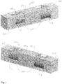
- CRYOTAINER 34000 LNG/40' ( Fig. 1 ) is intended for the long range transportation of liquefied natural gas and is assembled of two horizontal vessels 110 of 16.800 liter clamped into a standard frame 120 for a 40-foot ( ⁇ 12m long; in the following text as 40') container.
- Each pressure vessel 110 is horizontally embedded in the standard ISO 40 'container frame 120'.
- the pressure vessel 110 is defined of an inner shell 12 which is covered by an external coating formed by an outer coat 7.
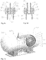
- the space between the inner shell 12 and the outer coat 7 is filled with an insulation arrangement 130 comprising a combination of insulating materials. ( Figure 7a , Figure 7b ).
- the insulation arrangement 130 from the inside towards the outside consists of at least one (two according to Fig. 7b ) set 131 of several (five with a thickness of 10-mm, as indicated in Fig. 7b ) nanostructure insulation layers 11 of cryogenic insulation based on an aerogel composition (total 100 mm).
- a composite material which contains homogeneous or heterogeneous aerogel phases with at least one additive incorporated either into the gel matrix (e.g. during synthesis) or added to the gel as a second distinct phase such as fibers, blankets, a fleece or also by a subsequent modification by compounding.
- the insulation arrangement 130 shown in Fig. 7a in connection with the storage vessel 300 is also applicable to the Tank container unit 100 and 100'.
- Figs. 1 and 2 show optional insulation casings 135 which completely surround the saddle structures 121 and clamping devices 30 described below.
- Each insulation layer 11 is particularly well-compressed by means of tapes 14 (see Fig. 8 ), that the individual insulation layers 11 are separated by a thin air space.
- an internally installed thermal shrinkable foil 10 in the thickness of 0.05 mm is installed.
- the thermal shrinkable foil 10 acts as vapor barrier.
- Each layer is compressed by means of strong bands 14.
- Toward the outer circumference of the vessel coat the insulation is followed by a filling layer 9 based on expanded foam for filling the gaps, which are the result of variations in the circumference of the container and built-in installations.
- Under the outer coat 7 is a 10 mm fire protection layer 8.
- the outer coat 7 is formed from thin metal sheets which form a completely sealed enclosure of the insulation arrangement 130 and serve as an additional vapor barrier.
- the sheets of the outer coat 7 are welded to each other and/or to a suitable substructure connected to the frame 120' or to the vessel 110.
- the fire protection layer 8 underneath serves as thermal shield during welding and protects the components of the insulation arrangement 130 underneath the fire protection layer 8.
- the fire protection layer 8 may also be based on an aerogel composition.
- the filling layer 9 may also be based on an aerogel composition, e.g. finely divided aerogel pieces or crumbs of aerogel with typical diameters below 1 cm for granules and 1 mm for powders which may be provided in suitable bags, filled blankets or flexible hoses.
- Fig. 8 shows a further detail of the insulation arrangement 130.
- Each insulation layer 11 is provided with a thermal radiation sheet layer 16 formed as metallic sheet (e.g. aluminum) which is attached to the insulation layer 11.
- Gaps 15 between adjoining insulation layers 11 (and radiation shield layers 16) are sealed with a sealing tape 18 with self sticking layer 19.
- Each gap 15 is also bridged in a radial direction to the outer coat 7 by a preceding and/or following insulation layer 11 for improved insulation.
- the insulation layers 11 are fixed and optionally compressed by surrounding tightening bands or tapes 14.
- the inner shell 12 of the vessel 110 is made of stainless steel.
- the pressure vessel 110 is equipped with installations for the loading and unloading, pressure indication, level and of the pressure control.
- the pressure vessel is built with two safety relief valves, which prevent excessive increase in pressure in the tank due to gasification of liquefied gas.
- two pressure vessels 110 of the same size are arranged horizontally along a tank vessel axis 112. Each of these vessels 110 can be used due to installation that is functioning independently.
- the temperature elongations of the tank support structures formed as clamping devices 30 are neutralized by special mounting (clamping) of the vessel.
- the mounting into in a container frame is designed so that it allows the movement of the vessel due to thermal shrinkage or expansion.
- the vessel 110 is mounted in a fixed frame 120' of the tank container 100.
- the vessel support legs in a form of steel plate elements 33 have openings 37 (e.g. formed as elongated holes) that allow the movement - shrinkage - of the vessel due to temperature or strain within the frame.
- Joint elements 36 formed as screws are tightened with a force that does not cause excessive friction. Further suitable joint elements are bolt elements.
- a specificity of such clamping device 30 is the low thermal conductivity, which is achieved by a sandwich structure comprising a (first) steel plate element 34 which is welded to a saddle structure 121 of the frame 120'. Plate element 34 is sandwiched between two (second) steel plate elements 33 welded to the tank vessel inner shell 12 via a doubler plate 35 ( Figs. 6a and 6c ). Between the first plate element 34 and the second plate elements 33 insulation plate elements 32 are arranged, formed from suitable material having a low thermal conductivity and a suitable brittle resistance at very low temperatures (e.g. PTFE (Teflon) or reinforced plastic sheet material) which reduce the thermal conductivity between the vessel 110 and the frame 120'. Carbon steel (28 W / mK) conductivity is much higher than a typical thermal conductivity of PTFE (0.23 W / mK) panels.
- suitable material having a low thermal conductivity and a suitable brittle resistance at very low temperatures
- the whole sandwich structure of the clamping device 30 is compressed by the joint elements 36, which penetrate corresponding openings 37 in the plate elements 32, 33,34.
- the cross sectional dimension of the opening 37 exceeds in at least one direction the cross sectional dimension of the penetrating joint element 36 to reduce the contact area between the joint element 36 and the inner face of the opening 37.
- the opening 37 can be formed as an elongated hole (dashed outline 37') or with a circular diameter exceeding a smaller diameter of the joint element 36.
- the openings 37, 37' allow for displacement movements in a longitudinal direction L and in a radial direction R.
- the compressing force is exceeded by the head elements 38 of the joint element 36 configured as bolts and the nuts tightened on the thread of the bolt acting as a tie rod.
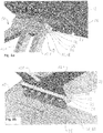
- FIG. 6a and 6b Details of the reduction of thermal bridge is shown in Figures 6a and 6b , with the structure containing PTFE insulation panels formed as insulation plate elements 32 and panels acting as stabilizing plate elements 31 made of metal (e.g. carbon steel).
- the insulation plate elements 32 and stabilizing plate elements 31 are optionally provided to improve the insulation capacity of the clamping device 30.
- a pair of an insulation plate element 32 and a stabilizing plate element 31 is arranged between the first 34 and the second plate element 33 or between at least one of the head elements 38 and the first 34 and/or the second plate element 33. (see Fig. 6b ) In the arrangement shown in Fig.
- the first plate elements 34 are part of box shaped saddle piece 39 connected to the saddle structure 121 which is sandwiched between insulation plate elements 32 and the second plate elements 33 connected to the vessel 110.
- the plate elements 31, 32, 33 and 34 extend in a longitudinal direction, parallel to a tank vessel axis 112. Depending of the cross sectional design of the openings 37 and the corresponding joint elements 36 a controlled sliding movement between the first plate elements 34 and the second plate elements 33 is possible at least at the clamping devices 30 at one end of the vessel which may occur due to thermal expansion or contraction.
- the plate elements 31, 32, 33 and 34 also extend in a radial direction to the vessel axis 112 they also allow for a radial displacement of the first plate element 34 relative to the second plate element 33.
- Fig. 9 shows an embodiment in which the thermal insulation between the frame 120' and the vessel is further improved.
- a connecting plate 40 is sandwiched between insulation plate elements 32 and first plate elements 34 on the vessel side and second plate elements 33 on the frame side.
- Optional pairs of insulation plate elements 32 and stabilizing plate 31 elements are also provided to improve the insulation capacity of such a support structure.
- the connecting plate 40 is fabricated from steel or a different suitable material which meets the structural requirements necessary to transfer all operational (dynamic and static) loads between the vessel and the frame.
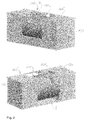
- Intermodal unit CRYOTAINER 16800 LNG/20' ( Figs. 2 and 5 ) is intended for local transport of liquefied natural gas and is composed of a horizontal vessel 110 of 16.800 liter volume clamped into a standard 20-foot (some 6m; v as 20' in the following text) frame 120'.
- Pressure vessel 110 is horizontally embedded in the standard ISO 40 'container frame 120'. All further features and embodiments of the insulation arrangement 130, clamping devices 30 and the saddle structure 121 described above in connection with embodiment 1 also apply to the tank container 100' with a single vessel 110 according to embodiment 2 ( Fig. 2 and 5 ).
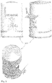
- the vertical stationary pressure vessel 200 CARD 8600 LNG ( Fig. 3 ) is intended for storage and distribution of liquefied natural gas.
- the volume of the vessel is 8.600 liter (the family extends from 8.600 to 15.000 liter).
- This vessel presents a cost effective alternative to local supply of customers on low population density areas, where a pipeline solution would prove not feasible due to high capital involvement.
- the use of liquefied natural gas in supply of medium and small consumers can present an option also for the supply of vehicles in traffic where it is one of the cleanest and environmentally most favorable solutions. All further features and embodiments of the insulation 130 described above in connection with embodiments 1 and 2 also apply to the vertical stationary vessel 200 according to embodiment 3.
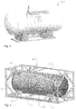
- the horizontal stationary pressure vessel 300 CARD 15600 LNG ( Fig. 4 ) is intended for distribution of liquefied natural gas.
- the volume of the vessel is 15.600 liter (the family of vessels is in the range from 8.600 to 27.000 liter).
- This vessel presents a cost effective alternative to local supply of customers on low population density areas, where a pipeline solution would prove not feasible due to high capital involvement.
- the use of liquefied natural gas in supply of medium and groups of small consumers can present an option also for the supply of vehicles in traffic where it is one of the cleanest and environmentally most favorable solutions.
- the vessel is supported by a foundation insulated with foam glass. All further features and embodiments of the insulation 130 described above in connection with embodiments 1 and 2 also apply to the horizontal stationary vessel 300 according to embodiment 4.
- the method of insulation of tank containers is not based on conventional vacuum insulation but on nanostructure insulation arrangement 130.
Landscapes
- Engineering & Computer Science (AREA)
- Mechanical Engineering (AREA)
- General Engineering & Computer Science (AREA)
- Physics & Mathematics (AREA)
- Thermal Sciences (AREA)
- Filling Or Discharging Of Gas Storage Vessels (AREA)
Description
- The invention relates to the development of cryogenic equipment for transport and storage of liquefied gases where the family of cryogenic equipment for transport and storage consist of horizontal and vertical vessels and transportable - mobile equipment in ISO containers.
- The invention specifically relates to a tank container for the transport and storage of cryogenic liquefied gas, comprising a framework and a cylindrical vessel connected to the framework.
- The current existing technological solutions based on technologies of performance of traditional insulation, which are also applicable in other insulation applications, such as the use of vacuum insulated cryogenic vessels with applications to storage and transport containers and expanded foam, expanded glass, perlite and similar inorganic materials. The traditional insulation of cryogenic tanks is considered to still require a significant low vacuum for successful operation. Insulation based on nanostructure gels has already achieved in atmospheric pressure values of insulation, which are better than in comparable existing materials, but the available potential and properties that are not to be found in conventional materials is exploited in this application.
- Cryogenic gases are stored in liquid form at extremely low temperatures. Fields of application are expanding along with increased technological possibilities in the industry and energy supply. Of the liquefied gas used most are liquefied natural gas, liquefied nitrogen, liquefied oxygen, argon and CO2. The temperature of liquefied gas goes down to -196 ° C (liquid nitrogen - LIN), oxygen (LOX) and argon (LAR), natural gas (LNG) at -163 ° C, carbon dioxide (LCO2) is the warmest with temperatures ranging from -40 ° C down to -80 ° C.
- The introduction of the liquefied methane industry in the supply system and group of consumers in some countries of the world (Brazil, Indonesia) achieved a remarkable delivery volume. Expansion of gas pipeline network is capital intensive and is difficult in areas with low consumption population density; the supply of liquefied gas provides the introduction of gas in areas where the supply pipeline is possible only after a long period of growth in consumption. Introducing the use of liquefied natural gas in transport would significantly reduce the pressure on the market of liquid fuels. The presence of such equipment solutions on the market facilitates the development of such means of transport and facilitates the issue of pollution from particulates and pollutant gases in urban and densely populated regions, where the work force carry out hundreds of kilometers of journeys per day. The supply of natural gas as an energy provider has taken place so far exclusively through primary, secondary and tertiary networks of gas pipelines. Construction of gas pipelines is capital intensive and requires at least a basic supply of gas to enough powerful customers. This condition is unavailable in many locations in a real short time. Alternative in this regard is the introduction of LNG in smaller tanks, which would provide for such monthly consumption at the specified location (a small industry or residential area) for the supply of liquefied gas would need modified mobile containers for the transport of liquefied gas to the local reservoirs.
US2008 0307798 A1 discloses a cryogen tank using aerogel for insulation purposes. InDE patent No. 1165624 B a tank container for the transport and storage of a cryogenic liquefied gas comprising a framework and an insulated cylindrical vessel connected to the framework by a clamping device is disclosed. On the outer shell of the cylindrical vessel two or more clamping means are fixedly positioned. Said clamping means consist of a rubber-metal-rubber element covered with plates. One plate is connected directly or via a bridge to the outer shell of the cylindrical vessel and the other plate is connected to the seating on the framework and by a lower stop and sliding wedges the cylindrical vessel is locked to prevent its movements in lateral and longitudinal direction. A clamp is provided which extends over the clamping device. The lower stop and the clamp prevent the movements of the cylindrical vessel. - For storage and transport of liquefied gases have hitherto been used tanks or tank containers with superinsulation features (thermal conductivity of the insulation material below 0.020 W /mK) realized by a double-vessel design wherein the space between the two vessels is vacuumed. Production of such double container and vacuuming of the dead space is technologically very demanding and expensive. Thus, the container must be serviced annually for vacuuming dead space, which can last several weeks, while all the time necessary for restoring the insulation the tank is useless.
- The underlying problem of the present invention is therefore to provide a transport or storage tank, specifically a tank container for cryogenic gases like LNG, LOX, LIN or LAR, which allows for a high transport capacity, a low tare weight, a superinsulation arrangement with low maintenance and a simple structural design suitable for a high temperature difference between the tank vessel and the framework.
- This problem is solved by a tank container according to claim 1. Such a tank container for the transport and storage of cryogenic liquefied gas, comprises a framework and a cylindrical vessel connected to the framework, wherein the vessel is covered by a superinsulation arrangement based on an aerogel composition, and the vessel is connected to the framework by an insulating clamping device which is adapted to allow for a relative movement between the framework and the vessel due to thermal expansion or contraction of the vessel.
Further embodiments of the present invention are indicated in the claims 2 to 11, the following description and the drawings. - The equipment based on the invention differs from the current solutions in the technology of insulation: The insulation is improved, the storage time is prolonged, manufacturing times are shortened, reduced material in quantity and the need for vacuum as the traditional technology of insulation is eliminated.
The introduction of new technologic procedures, new materials and new composites contribute to the solution of technological difficulties, which are not satisfactorily resolved (thermal bridges on supports, losses on functional piping and valves, etc.). In the production significant time is saved due to shorter timing between manufacturing operations. The vacuum insulated vessel requires two shells - an outer and an inner shell capable of operation under pressure conditions. The result is double quantity of material and at least double mass of the vessel. The manufacture of two complex vessels takes at least double time (the cryo temperature set due to exquisite complexity range the highest requirements). Also the process of establishing vacuum is slow, and the problem of maintaining vacuum remains. A great portion of time dedicated in the production of vacuum insulated vessels is necessary for the vacuuming process. In addition to this the vacuum through time is lost and regular vacuuming is necessary. The established solutions require repeated vacuuming every 290 to 365 days. The process of vacuuming takes some 250 to 550 hours. The vessel insulated with the solution presented in the invention can be manufactured in shorter time - a single pressure vessel, lighter - the mechanical protection is one tenth of the vacuum protection, less sensitive to mechanical and fire loads. - The developed procedures allow significant saving in material with the lighter vessel shell, faster installation of the insulation and better control over local deviations, the possibility of insulation of connecting piping all contribute to evaporation rates under 0,38% of full load per day.
- The installation of cryogenic vessels in container frames enables multimodal transport within the scope of ADR (road) and RID (rail) and IMDG (sea). Such an implementation can relieve the road transportation and enable access to specific locations.
- The cryogenic insulation is suitable for cryo temperatures and also demonstrates in case of flammable gases fire resistance. During the filling the liquefied gas at temperature of gas - 186 °C (LIN) to - 161 °C (LNG) at ambient pressure. During transport or longer storage the temperature would raise to -135 °C, and the pressure in the vessel rises to 6 bars due to heat transfer from the ambient through the insulation. This is the limited pressure where the safety relief valves start to operate or we need to direct the gas to immediate consumption. The insulation is very important for the function of the tank. For the stationary storage tanks the quantity of evaporated gas in a period of time is limited with losses under 0.38% of full load. The evaporation value is determined based on trial operation.
- The insulation of vessels with a modem and innovative insulating material based on nanostructure gels based on aerogel material according to the invention avoids the disadvantages of vacuum insulation. High-tech nano-insulation has extremely good insulating properties. Base material formed aerogel, which has in its structure of nano-size pores, which trap molecules of air, which eliminates nearly three modes of heat transfer - convection, -conduction and -radiation and are also flame-retardant. At the same time the material is mechanically stable at temperatures down to -200 °C. These properties in the other traditional insulation materials are not common.
- The development of vessels with insulation based on nanostructure gels enables the elimination of vacuum. The advantages are directly in the field of the inner and outer vessel shell, both are significantly lighter in weight that means:
- The direct material saving for a CRYOTAINER 34000 LNG/40' example is some 10.000 kg. This results in more freight with one shipment. It allows for faster production procedures for material preparation and shorter time for production.
- Prefabrication of insulation material with a specialized work group can reduce the insulation time and the overall finalization of products.
- The heat transfer from the ambient to the liquefied gas presents a difficulty, a portion of liquefied gas in the vessel is evaporating, and introduction of efficient insulation is essential. The introduction of innovative solutions based on nanostructure insulation materials provides also properties other than insulation alone. These required properties are resistance to low temperatures, fire resistance, light weight, water repellence, vapor permeability and adequate handling qualities.
- The new technology allows for significant savings on material and time of production, and in addition offers safety. In case of mechanical damage of the outer shell the nanostructure insulation enables, in contrast to conventional vacuum, continuous heat shielding and prevents immediate evaporation in case of vacuum collapse and extends by a multiplier the available time for salvage. In vacuum vessels the damage causes immediate rise of pressure in the vacuum to the level of the atmosphere. With the rising pressure the vacuum loses its insulating properties and very fast evaporation of liquefied gas takes place.
- In case of direct fire exposure the new technology of insulation prevents any rise of temperature in the media for at least 120 minutes.
- The family of cryogenic vessels for transport and storage of liquefied gases is composed of stationary horizontal vessels of 8600 to 27000 liters. In addition to the horizontal there is a family of vertical vessels with 8600 to 15000 liters. The family of transportable (intermodal) vessels in ISO container frames is two models with 16800 and 32600 liter volume.
- The pressure vessel is composed of an inner shell and an outer coat. The intermediate space is filled with a combination of insulating materials. The insulation from inside towards outside is composed from four to seven 10 mm thick layers of cryogenic protection (in total from 80 to 140mm) made of nanostructure insulating material (based on aerogel). Every layer is compressed with bands, so that there is no space for air in between. After four or seven layers there is a
thermal shrink foil 10 of 0.038 to 0.12mm thick. This shrink foil has the role of a vapor barrier. The next four to seven layers of insulation are installed. Every layer is compressed with bands. The next thermo shrink foil is installed. Toward the outer coat of the vessel expanded insulation foam (thickness 30 to 50 mm) has to fill out the voids resulting from the deviations between the outer shape and the piping installations. Directly under the outer coat there is 6 to 18 mm fire protection. The introduction of insulation with at least 120 minute fire resistance presents an additional contribution to fire damage risk. - Existing vacuum insulated tanks have an outer shell made of construction steel 10mm thick and reinforced with U profiles in order to prevent the collapse due to outer pressure. In the present invention the nanostructure insulated vessels have an outer coat of only 1 mm thickness of stainless steel. The intermodal unit CRYOTAINER 34000LNG/40' is some 10.000 kg lighter than comparable tanks with vacuum insulation. The difference in environmental load in the manufacture is significant it saves 10000 kg of steel and eliminates also the emissions to the environment derived from steel production. In stabile units the difference is equal depending on the size of the vessel.
- The stationary tanks are intended to replace the liquefied petrol gas (LPG) that is in production directly connected to the available crude oil production. This product enables direct replacement on the market in municipal areas where there are no conditions established for a pipeline connection.
- Embodiments, features and further details of the present invention are explained in the following on the basis of the drawings in which
- Fig. 1
- shows perspective views of a first embodiment of a tank container according to the present invention (Unit CRYOTAINER 34000 LNG/40');
- Fig. 2
- shows perspective views of a second embodiment of a tank container according to the present invention (Unit CRYOTAINER 16800 LNG/20');
- Fig. 3
- shows perspective views of an embodiment of a storage container (Vertical stabile unit CARD 8600 LNG); shows a further embodiment of a storage container (Florizontal stationary
- Fig. 4
- unit
- Fig. 5
- shows the tank container of
Fig. 2 including the arrangements of supports structures in the frame without the insulation; - Fig. 6a to d
- show details of the support structure with clamping device of the tank container shown in
Figs. 1 ,2 and5 - Fig. 7a, b
- show in a schematic manner the nanostructure insulation arrangement on the stationary horizontal tank shown in
Fig. 3 also realized on the tank container according to the present invention - Fig. 8
- shows a further detail of the insulation arrangement of
Fig. 7a , b; - Fig. 9
- shows in a schematic manner a further embodiment of a support structure for a tank container according to the present invention;
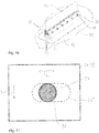
- Fig. 10
- shows a perspective view of a clamping device according to
Fig. 6c ; and - Fig. 11
- shows a detail of a clamping device.
- "Intermodal"
tank container unit 100 CRYOTAINER 34000 LNG/40' (Fig. 1 ) is intended for the long range transportation of liquefied natural gas and is assembled of twohorizontal vessels 110 of 16.800 liter clamped into astandard frame 120 for a 40-foot (∼ 12m long; in the following text as 40') container. - Each
pressure vessel 110 is horizontally embedded in the standard ISO 40 'container frame 120'. Thepressure vessel 110 is defined of aninner shell 12 which is covered by an external coating formed by anouter coat 7. The space between theinner shell 12 and theouter coat 7 is filled with aninsulation arrangement 130 comprising a combination of insulating materials. (Figure 7a ,Figure 7b ). - The
insulation arrangement 130 from the inside towards the outside consists of at least one (two according toFig. 7b ) set 131 of several (five with a thickness of 10-mm, as indicated inFig. 7b ) nanostructure insulation layers 11 of cryogenic insulation based on an aerogel composition (total 100 mm). In the present case, a composite material which contains homogeneous or heterogeneous aerogel phases with at least one additive incorporated either into the gel matrix (e.g. during synthesis) or added to the gel as a second distinct phase such as fibers, blankets, a fleece or also by a subsequent modification by compounding. Theinsulation arrangement 130 shown inFig. 7a in connection with the storage vessel 300 is also applicable to theTank container unit 100 and 100'. -
Figs. 1 and2 showoptional insulation casings 135 which completely surround thesaddle structures 121 and clampingdevices 30 described below. - Each
insulation layer 11 is particularly well-compressed by means of tapes 14 (seeFig. 8 ), that the individual insulation layers 11 are separated by a thin air space. After each five of insulation layers an internally installed thermalshrinkable foil 10 in the thickness of 0.05 mm is installed. The thermalshrinkable foil 10 acts as vapor barrier. Then there are five additional insulation layers 11 placed to insulate cryogenic temperature range. Each layer is compressed by means ofstrong bands 14. After a total of teninsulation layers 11 again the same thermalshrinkable foil 10 is placed. Toward the outer circumference of the vessel coat the insulation is followed by afilling layer 9 based on expanded foam for filling the gaps, which are the result of variations in the circumference of the container and built-in installations. Under theouter coat 7 is a 10 mm fire protection layer 8. - The
outer coat 7 is formed from thin metal sheets which form a completely sealed enclosure of theinsulation arrangement 130 and serve as an additional vapor barrier. For this purpose the sheets of theouter coat 7 are welded to each other and/or to a suitable substructure connected to the frame 120' or to thevessel 110. The fire protection layer 8 underneath serves as thermal shield during welding and protects the components of theinsulation arrangement 130 underneath the fire protection layer 8. - The fire protection layer 8 may also be based on an aerogel composition. Also, the
filling layer 9 may also be based on an aerogel composition, e.g. finely divided aerogel pieces or crumbs of aerogel with typical diameters below 1 cm for granules and 1 mm for powders which may be provided in suitable bags, filled blankets or flexible hoses. -
Fig. 8 shows a further detail of theinsulation arrangement 130. Eachinsulation layer 11 is provided with a thermalradiation sheet layer 16 formed as metallic sheet (e.g. aluminum) which is attached to theinsulation layer 11.Gaps 15 between adjoining insulation layers 11 (and radiation shield layers 16) are sealed with a sealing tape 18 withself sticking layer 19. Eachgap 15 is also bridged in a radial direction to theouter coat 7 by a preceding and/or followinginsulation layer 11 for improved insulation. The insulation layers 11 are fixed and optionally compressed by surrounding tightening bands ortapes 14. - The
inner shell 12 of thevessel 110 is made of stainless steel. Thepressure vessel 110 is equipped with installations for the loading and unloading, pressure indication, level and of the pressure control. The pressure vessel is built with two safety relief valves, which prevent excessive increase in pressure in the tank due to gasification of liquefied gas. - In the
frame 120 of 40 ' tank container unit twopressure vessels 110 of the same size are arranged horizontally along atank vessel axis 112. Each of thesevessels 110 can be used due to installation that is functioning independently. - Large temperature difference causes some material elongation or in this case shrinkage. According to the invention the temperature elongations of the tank support structures formed as clamping devices 30 (see
Figs. 5 ,6a to d ) are neutralized by special mounting (clamping) of the vessel. The mounting into in a container frame is designed so that it allows the movement of the vessel due to thermal shrinkage or expansion. Thevessel 110 is mounted in a fixed frame 120' of thetank container 100. The vessel support legs in a form ofsteel plate elements 33 have openings 37 (e.g. formed as elongated holes) that allow the movement - shrinkage - of the vessel due to temperature or strain within the frame.Joint elements 36 formed as screws are tightened with a force that does not cause excessive friction. Further suitable joint elements are bolt elements. - A specificity of
such clamping device 30 is the low thermal conductivity, which is achieved by a sandwich structure comprising a (first)steel plate element 34 which is welded to asaddle structure 121 of the frame 120'.Plate element 34 is sandwiched between two (second)steel plate elements 33 welded to the tank vesselinner shell 12 via a doubler plate 35 (Figs. 6a and6c ). Between thefirst plate element 34 and thesecond plate elements 33insulation plate elements 32 are arranged, formed from suitable material having a low thermal conductivity and a suitable brittle resistance at very low temperatures (e.g. PTFE (Teflon) or reinforced plastic sheet material) which reduce the thermal conductivity between thevessel 110 and the frame 120'. Carbon steel (28 W / mK) conductivity is much higher than a typical thermal conductivity of PTFE (0.23 W / mK) panels. - The whole sandwich structure of the
clamping device 30 is compressed by thejoint elements 36, which penetrate correspondingopenings 37 in theplate elements - As shown in
Fig. 11 the cross sectional dimension of theopening 37 exceeds in at least one direction the cross sectional dimension of the penetratingjoint element 36 to reduce the contact area between thejoint element 36 and the inner face of theopening 37. For this purpose theopening 37 can be formed as an elongated hole (dashed outline 37') or with a circular diameter exceeding a smaller diameter of thejoint element 36. Theopenings 37, 37' allow for displacement movements in a longitudinal direction L and in a radial direction R. - In the present case the compressing force is exceeded by the
head elements 38 of thejoint element 36 configured as bolts and the nuts tightened on the thread of the bolt acting as a tie rod. - Details of the reduction of thermal bridge is shown in
Figures 6a and 6b , with the structure containing PTFE insulation panels formed asinsulation plate elements 32 and panels acting as stabilizingplate elements 31 made of metal (e.g. carbon steel). Theinsulation plate elements 32 and stabilizingplate elements 31 are optionally provided to improve the insulation capacity of theclamping device 30. Typically, such a pair of aninsulation plate element 32 and a stabilizingplate element 31 is arranged between the first 34 and thesecond plate element 33 or between at least one of thehead elements 38 and the first 34 and/or thesecond plate element 33. (seeFig. 6b ) In the arrangement shown inFig. 6a and6d , thefirst plate elements 34 are part of box shapedsaddle piece 39 connected to thesaddle structure 121 which is sandwiched betweeninsulation plate elements 32 and thesecond plate elements 33 connected to thevessel 110.
Theplate elements tank vessel axis 112. Depending of the cross sectional design of theopenings 37 and the corresponding joint elements 36 a controlled sliding movement between thefirst plate elements 34 and thesecond plate elements 33 is possible at least at theclamping devices 30 at one end of the vessel which may occur due to thermal expansion or contraction. As theplate elements vessel axis 112 they also allow for a radial displacement of thefirst plate element 34 relative to thesecond plate element 33. -
Fig. 9 shows an embodiment in which the thermal insulation between the frame 120' and the vessel is further improved. A connectingplate 40 is sandwiched betweeninsulation plate elements 32 andfirst plate elements 34 on the vessel side andsecond plate elements 33 on the frame side. Optional pairs ofinsulation plate elements 32 and stabilizingplate 31 elements are also provided to improve the insulation capacity of such a support structure. The connectingplate 40 is fabricated from steel or a different suitable material which meets the structural requirements necessary to transfer all operational (dynamic and static) loads between the vessel and the frame. - Intermodal unit CRYOTAINER 16800 LNG/20' (
Figs. 2 and5 ) is intended for local transport of liquefied natural gas and is composed of ahorizontal vessel 110 of 16.800 liter volume clamped into a standard 20-foot (some 6m; v as 20' in the following text) frame 120'. -
Pressure vessel 110 is horizontally embedded in the standard ISO 40 'container frame 120'. All further features and embodiments of theinsulation arrangement 130, clampingdevices 30 and thesaddle structure 121 described above in connection with embodiment 1 also apply to the tank container 100' with asingle vessel 110 according to embodiment 2 (Fig. 2 and5 ). - The vertical
stationary pressure vessel 200 CARD 8600 LNG (Fig. 3 ) is intended for storage and distribution of liquefied natural gas. The volume of the vessel is 8.600 liter (the family extends from 8.600 to 15.000 liter). This vessel presents a cost effective alternative to local supply of customers on low population density areas, where a pipeline solution would prove not feasible due to high capital involvement. The use of liquefied natural gas in supply of medium and small consumers can present an option also for the supply of vehicles in traffic where it is one of the cleanest and environmentally most favorable solutions. All further features and embodiments of theinsulation 130 described above in connection with embodiments 1 and 2 also apply to the verticalstationary vessel 200 according to embodiment 3. - The horizontal stationary pressure vessel 300 CARD 15600 LNG (
Fig. 4 ) is intended for distribution of liquefied natural gas. The volume of the vessel is 15.600 liter (the family of vessels is in the range from 8.600 to 27.000 liter). This vessel presents a cost effective alternative to local supply of customers on low population density areas, where a pipeline solution would prove not feasible due to high capital involvement. The use of liquefied natural gas in supply of medium and groups of small consumers can present an option also for the supply of vehicles in traffic where it is one of the cleanest and environmentally most favorable solutions. - The vessel is supported by a foundation insulated with foam glass. All further features and embodiments of the
insulation 130 described above in connection with embodiments 1 and 2 also apply to the horizontal stationary vessel 300 according to embodiment 4. - The following features are realized at least partly in the embodiments described above and specifically in the
tank container 100, 100' according to the present invention. - 1. The
tank container 100, 100' for transport and storage of liquefied gas is identified wherein as the basic means of insulation the cryogenic insulation is used, predominantly nanostructure insulation based on aerogel and that there is no need for vacuum or below atmospheric pressure. - 2. The
tank container 100, 100' from point 1 is identified by the insulation between theinner shell 12 andouter coat 7 which is composed from the following components:- a. The layer close to the
outer coat 7 includes from 7 to 14 cryogenic insulation layers 11 in a total thickness of 80 - 140 mm; - b. Optionally on a radiation shield layers 16 enveloping or separating the cryogenic insulation layers 11 one or more thermal shrinkable foils 10 are placed 0.038 - 0.12 mm thick or some other element that serves as vapor protection and as a separation layer during eventual possible dismantling of the cryogenic insulation;
- c. Optionally layers of
insulation foam 9, preferably expanded foam in the thickness of 30 - 50 mm, that will fill the void to the fire protection layer 8; - d. Optionally a fire protection layer 8 follows 6 - 18 mm thick, preferably nanostructure aerogel, which is fixed to the
outer coat 7.
- a. The layer close to the
- 3. The
tank container 100, 100' in point 1 - 2 is identified with the evaporation rates of less than 0.36% of full load per day. - 4. The
tank container 100, 100' in point 1-3 is identified with the property of fire resistance preventing the temperature to rise, is at least 60 minutes preferably 120 minutes - 5. The
tank container 100, 100' in point 1 - 4 is identified with the volumes of containerized tanks are 16.800 liter and 32.600 liter - 6. The
tank container 100, 100' in point 1 - 4 is identified with the volumes ofstorage tanks 110 are 8.600 liter in 27.000 liter - 7. The
tank container 100, 100' in point 1 - 5 is identified with the clampingdevice 30 in the ISO container is executed so that it enables free movement of the shrinking. - 8. The
tank container 100, 100' inpoint 7, is identified with the clampingdevice 30 which is on one side (front or back) of thevessel 110 be fixed, on the other end of thevessel 110 is not fixed but thejoint elements 36 have space to allow deviations by means ofelongated holes 37 andjoint elements 36 are tightened by thehead elements 38 with low force that prevents most friction. - 9. The tank container in point 8, is identified with
specific clamping device 30 where for maximal effect the clamping device is insulated with PTFEinsulation plate elements 32 and stabilizingplate elements 31. - The method of insulation of tank containers is not based on conventional vacuum insulation but on
nanostructure insulation arrangement 130. - 10. The procedures to minimize the effect of the fixing of the vessel to the
outer coat 7 is designed on the reduction of the heat conductivity of the clamping device_30, - prolonged heat conduction path, - smaller contact surfaces, - corresponding mechanical resistance and rigidity that is obtained in the following way:- a. More stabilizing
plate elements 31 of thin sheet on the cold side; - b. More stabilizing
plate elements 31 of thin sheet on the warm side; - c. Separation - the space between the stabilizing
plate elements 31 is separated with aninsulation plate element 32 of fitting PTFE; - d. The
joint element 36 is protected against loosening, since the sole function is prevention of separation or dislocation of the joint.
- a. More stabilizing
Claims (11)
- A tank container (100, 100') for the transport and storage of cryogenic liquefied gas, comprising a framework (120, 120') and an insulated cylindrical vessel (110) connected to the framework (120, 120') characterized in that the vessel (110) is covered by a superinsulation arrangement (130) based on an aerogel composition and an outer cover sheet (7), wherein the superinsulation arrangement (130) consists of:- at least one set (131) of nanostructure insulation layers (11) based on an aerogel composition and each insulation layer (11) is provided with a thermal radiation shield layer (16) whereby each insulation layer (11) together with the thermal radiation shield layer (16) is compressed by a tape (14) and each set (131) is covered by a thermo shrinkable film (10) serving as a vapor barrier:- a gap (15) between adjoining insulation layers (11) and/or radiation shield layers (16) is bridged by at least one of the insulation layer (11), a radiation shield layer (16) or a sealing tape (18);and the vessel (110) is connected to the framework (120, 120') with a clamping device (30).
- The tank container (100, 100') according to claim 1, wherein a fire protection layer (8) is provided between the outer cover sheet (7) and the outer set (131) of insulation layers (11, 16).
- The tank container (100, 100') according to claim 1, characterized in that the clamping device (30) is a sandwich structure comprising at least one first plate element (34) connected to the framework (120, 120'), at least one second plate element (33) connected to the vessel (110) and an insulation plate element (32) arranged between the first (34) and the second plate element (33) and whereby within each of plate elements (34, 33, 32) openings (37) are formed and said plate elements (34, 33, 32) are interconnected by at least one joint element (36) interspersing said openings (37) and the dimensions of the openings (37) exceed in at least in one direction a cross sectional dimension of the penetrating joint element (36) to allow for a relative movement between the framework (120, 120') and the vessel (110) due to thermal expansion or contraction of the vessel (110).
- The tank container (100, 100') according to claim 3, wherein the sandwich structure additionally comprises a connecting plate (40) with openings (37) which extends in parallel to the first and second plate element (34, 33) and overlapping the first and second plate element (34, 33), wherein the first and the second plate elements (34, 33) are interconnected to the connecting plate (40) with an insulating plate element (32) in between.
- The tank container (100, 100') according to claim 4, wherein the connecting plate (40) is arranged between two first and/or two second plate (34, 33) elements.
- The tank container (100, 100') according to claims 3 to 5, wherein the sandwich structure comprises at least one pair of an additional stabilizing plate element (31) and an insulating plate element (32) which is either arranged between the first and the second plate element (34, 33) or between the first plate element (34) and the connecting plate (40) or between the second plate element (33) and the connecting plate (40).
- The tank container (100, 100') according to claims 3 to 6, wherein a main surface of the plate elements (31, 32, 33, 34, 39) extends along a longitudinal axis (112) of the cylindrical vessel (110).
- The tank container (100, 100') according to claims 3 to 7, wherein the joint element (36) is formed as a tie element compressing the sandwich structure between head elements (38) and the stabilizing plate element (31) rests against the head element (38).
- The tank container (100, 100') according to claims 3 to 8, wherein the first plate element (34) is welded to a saddle structure (121) of the framework (120, 120') and the second plate element (33) is welded to the vessel (110).
- The tank container (100, 100') according to claims 3 to 9, wherein the insulation plates (32) are manufactured from a fiber reinforced plastic material, specifically comprising a PTFE material.
- The tank container (100,100') according to previous claims, wherein a radial thickness of the insulation arrangement (130) corresponds to radial dimensions of the sandwich structure of the clamping device (30) in such a manner that the insulation plate elements (32) and the joint elements (36) of the clamping device (30) are completely covered by the insulation arrangement (130).
Applications Claiming Priority (2)
| Application Number | Priority Date | Filing Date | Title |
|---|---|---|---|
| SI201200040A SI24001A (en) | 2012-02-10 | 2012-02-10 | Cryogenic device for transport and storage of liquefaction gas |
| PCT/EP2013/052559 WO2013117706A1 (en) | 2012-02-10 | 2013-02-08 | Tank container for transport and storage of cryogenic liquefied gases |
Publications (2)
| Publication Number | Publication Date |
|---|---|
| EP2812624A1 EP2812624A1 (en) | 2014-12-17 |
| EP2812624B1 true EP2812624B1 (en) | 2018-01-17 |
Family
ID=47683732
Family Applications (1)
| Application Number | Title | Priority Date | Filing Date |
|---|---|---|---|
| EP13703580.4A Not-in-force EP2812624B1 (en) | 2012-02-10 | 2013-02-08 | Tank container for transport and storage of cryogenic liquefied gases |
Country Status (4)
| Country | Link |
|---|---|
| US (3) | US9488313B2 (en) |
| EP (1) | EP2812624B1 (en) |
| SI (1) | SI24001A (en) |
| WO (1) | WO2013117706A1 (en) |
Families Citing this family (10)
| Publication number | Priority date | Publication date | Assignee | Title |
|---|---|---|---|---|
| SI24001A (en) | 2012-02-10 | 2013-08-30 | Aerogel Card D.O.O. | Cryogenic device for transport and storage of liquefaction gas |
| USD785778S1 (en) * | 2013-11-20 | 2017-05-02 | Worthington Industries, Inc. | Fuel tank frame assembly |
| USD759229S1 (en) | 2013-11-20 | 2016-06-14 | Worthington Industries | Fuel tank frame assembly |
| CN104154415B (en) * | 2014-07-10 | 2016-04-20 | 新兴能源装备股份有限公司 | A kind of LNG of filling structure moves filling vehicle |
| CN105736903B (en) * | 2016-02-02 | 2018-05-01 | 上海交通大学 | Independent Type B LNG ship cargo tank adiabatic system with spatter shield structure |
| KR101933058B1 (en) * | 2018-06-12 | 2018-12-27 | (주)대웅씨티 | Tank containers for low-temperature liquefied gas |
| CA3077045A1 (en) * | 2019-03-25 | 2020-09-25 | Marathon Petroleum Company Lp | Insulation securement system and associated methods |
| KR102640059B1 (en) * | 2019-09-18 | 2024-02-26 | 삼성중공업(주) | Apparatus for supporting liquefied gas storage tank |
| DE102021102749B4 (en) * | 2021-02-05 | 2025-05-28 | Deutsche Holzveredelung Schmeing GmbH & Co. KG | Storage block for a tank for cryogenic liquids and method for manufacturing |
| EP4495473A1 (en) * | 2023-07-17 | 2025-01-22 | Airbus Operations, S.L.U. | A double-wall tank |
Family Cites Families (58)
| Publication number | Priority date | Publication date | Assignee | Title |
|---|---|---|---|---|
| US2188007A (en) | 1937-07-03 | 1940-01-23 | Samuel S Kistler | Inorganic aerogel compositions |
| NL268332A (en) * | 1960-08-17 | |||
| DE1165624B (en) * | 1961-11-15 | 1964-03-19 | Linke Hofmann Busch | Horizontally stored container with a large capacity for storing or transporting liquefied gases |
| US3583352A (en) * | 1968-12-24 | 1971-06-08 | Technigaz | Supporting device for self-carrying cylindrical or spherical storage tanks and its various applications |
| FR2321657A1 (en) * | 1975-08-22 | 1977-03-18 | Gaz Transport | TANK FOR THE STORAGE OF LIQUID PRODUCTS, IN PARTICULAR FOR VESSELS CARRYING LIQUEFIED NATURAL GAS |
| US4038832A (en) * | 1975-09-08 | 1977-08-02 | Beatrice Foods Co. | Liquefied gas container of large capacity |
| FR2463077A1 (en) * | 1979-08-07 | 1981-02-20 | Anf Ind | SYSTEM FOR FIXING A TANK IN A CONTAINER FRAME |
| DE2942180C2 (en) | 1979-10-18 | 1985-02-21 | Grünzweig + Hartmann und Glasfaser AG, 6700 Ludwigshafen | Process for the production of a heat insulating body |
| DE3108816A1 (en) | 1981-03-09 | 1982-09-30 | Grünzweig + Hartmann und Glasfaser AG, 6700 Ludwigshafen | THERMAL INSULATING COMPRESSION MATERIAL BASED ON MICROPOROUS OXIDAEROGEL FROM FLAME HYDROLYSIS, METHOD FOR THE PRODUCTION THEREOF, A FILM PRODUCED THEREOF AND A WASHED PRODUCT THEREFOR |
| US4481778A (en) * | 1983-03-21 | 1984-11-13 | Ball Corporation | Thermally disconnecting passive parallel orbital supports |
| US4717708A (en) | 1983-12-27 | 1988-01-05 | Stauffer Chemical Company | Inorganic oxide aerogels and their preparation |
| DE3429671A1 (en) | 1984-08-11 | 1986-02-20 | Basf Ag, 6700 Ludwigshafen | METHOD FOR PRODUCING AEROGELS |
| US4619908A (en) | 1984-12-24 | 1986-10-28 | Stauffer Chemical Company | Non-aged inorganic oxide-containing aerogels and their preparation |
| DE3890173C2 (en) | 1987-03-26 | 1992-11-19 | Matsushita Electric Works, Ltd., Kadoma, Osaka, Jp | |
| EP0497966B1 (en) | 1990-08-23 | 1997-10-29 | THE REGENTS OF THE UNIVERSITY OF CALIFORNIA as represented by Lawrence Livermore National Laboratory | A METHOD FOR PRODUCING METAL OXIDE AEROGELS HAVING DENSITIES LESS THAN 0.02 g/cm?3 |
| US5306555A (en) | 1991-09-18 | 1994-04-26 | Battelle Memorial Institute | Aerogel matrix composites |
| WO1993016125A1 (en) | 1992-02-18 | 1993-08-19 | Matsushita Electric Works, Ltd. | Process for producing hydrophobic aerogel |
| US5565142A (en) | 1992-04-01 | 1996-10-15 | Deshpande; Ravindra | Preparation of high porosity xerogels by chemical surface modification. |
| TW261654B (en) * | 1993-05-20 | 1995-11-01 | Ishikawajima Harima Heavy Ind | |
| DE4430642A1 (en) | 1994-08-29 | 1996-03-07 | Hoechst Ag | Airgel and xerogel composites, processes for their production and their use |
| DE4430669A1 (en) | 1994-08-29 | 1996-03-07 | Hoechst Ag | Process for the production of fiber-reinforced xerogels and their use |
| DE4441567A1 (en) | 1994-11-23 | 1996-05-30 | Hoechst Ag | Airgel-containing composite material, process for its production and its use |
| CA2205845A1 (en) | 1994-11-23 | 1996-05-30 | Hoechst Aktiengesellschaft | A composite material comprising an aerogel, a process for its preparation, and its use |
| CA2208510A1 (en) | 1994-12-21 | 1996-06-27 | Hoechst Aktiengesellschaft | Fiber web/aerogel composite material comprising bicomponent fibers, production thereof and use thereof |
| DE4447345C1 (en) * | 1994-12-31 | 1996-05-02 | Magerl Feinmechanik Gmbh | Infinitely adjustable support for workpieces in machine tools |
| US6887563B2 (en) | 1995-09-11 | 2005-05-03 | Cabot Corporation | Composite aerogel material that contains fibres |
| DE19541279A1 (en) | 1995-11-06 | 1997-05-07 | Hoechst Ag | Process for the production of organically modified aerogels using alcohols |
| AU7720596A (en) | 1995-11-09 | 1997-05-29 | Aspen Systems, Inc. | Flexible aerogel superinsulation and its manufacture |
| DE19548128A1 (en) | 1995-12-21 | 1997-06-26 | Hoechst Ag | Nonwoven airgel composite material containing at least one thermoplastic fiber material, process for its production and its use |
| US5972254A (en) | 1996-12-06 | 1999-10-26 | Sander; Matthew T. | Ultra-thin prestressed fiber reinforced aerogel honeycomb catalyst monoliths |
| US6197270B1 (en) | 1996-12-20 | 2001-03-06 | Matsushita Electric Works, Ltd. | Process for producing aerogel |
| DE19718741A1 (en) | 1997-05-02 | 1998-11-05 | Hoechst Ag | Process for compacting aerogels |
| US5962539A (en) | 1997-05-09 | 1999-10-05 | Separex S.A. | Process and equipment for drying a polymeric aerogel in the presence of a supercritical fluid |
| US5973015A (en) | 1998-02-02 | 1999-10-26 | The Regents Of The University Of California | Flexible aerogel composite for mechanical stability and process of fabrication |
| DE19834265A1 (en) | 1998-07-30 | 2000-02-17 | Thomas Gesner | Process for the production of airgel and plant for the production of airgel layers on substrates or products consisting of airgel |
| US6187250B1 (en) | 1998-08-19 | 2001-02-13 | James Champagne | Continuous gel casting method and apparatus |
| EP1230008A1 (en) | 1999-10-21 | 2002-08-14 | Aspen Systems, Inc. | Rapid aerogel production process |
| BR0115523A (en) | 2000-12-22 | 2003-09-16 | Aspen Aerogels Inc | Composite |
| US20030029877A1 (en) * | 2001-07-30 | 2003-02-13 | Mathur Virendra K. | Insulated vessel for storing cold fluids and insulation method |
| US6770584B2 (en) | 2002-08-16 | 2004-08-03 | The Boeing Company | Hybrid aerogel rigid ceramic fiber insulation and method of producing same |
| DE10302394A1 (en) * | 2003-04-16 | 2004-12-30 | Mlu Halle-Wittenberg | Thermal expansion compensating device between two different components has metal feet and a web plate consisting of several lamella slats of fibre-reinforced plastics |
| PL3120983T5 (en) | 2003-06-24 | 2024-04-22 | Aspen Aerogels, Inc. | Continuous sheet of gel material and continuous sheet of aerogel material |
| US20070228045A1 (en) * | 2004-03-05 | 2007-10-04 | Goldbach Robert D | Support Assemblies and Systems for Semi-Membrane Tanks |
| FR2877639B1 (en) * | 2004-11-10 | 2006-12-15 | Gaz Transp Et Technigaz Soc Pa | SEALED AND THERMALLY INSULATED TANK INTEGRATED WITH THE SHELLING STRUCTURE OF A SHIP |
| DE102005013620B3 (en) * | 2005-03-24 | 2006-07-27 | Bruker Biospin Ag | Cryostat device for storing cryogenic fluid in cryo container, has centering units loaded independent of temperature within device to constant pressure or traction within certain range of pressure or traction obtained at room temperature |
| WO2007011750A2 (en) | 2005-07-15 | 2007-01-25 | Aspen Aerogels, Inc. | Secured aerogel composites and method of manufacture thereof |
| WO2007079244A2 (en) | 2005-12-29 | 2007-07-12 | Aspen Aerogels, Inc. | Improved gel production via multi-stream mixing |
| US7781492B2 (en) * | 2006-06-08 | 2010-08-24 | The United States Of America As Represented By The Administrator Of The National Aeronautics And Space Administration | Foam/aerogel composite materials for thermal and acoustic insulation and cryogen storage |
| US20080307798A1 (en) * | 2007-06-12 | 2008-12-18 | Yang Luo | Cryogenic liquid tank and method |
| DE102008052877A1 (en) * | 2008-10-23 | 2010-04-29 | Linde Aktiengesellschaft | storage device |
| US20100146992A1 (en) * | 2008-12-10 | 2010-06-17 | Miller Thomas M | Insulation for storage or transport of cryogenic fluids |
| EP2429948A4 (en) | 2009-04-27 | 2017-09-06 | Cabot Corporation | Aerogel compositions and methods of making and using them |
| EP2462291A1 (en) * | 2009-08-07 | 2012-06-13 | Conocophillps Company | Cryogenic insulation attachment and method |
| US8899000B2 (en) * | 2010-07-09 | 2014-12-02 | Birdair, Inc. | Architectural membrane and method of making same |
| NO333035B1 (en) * | 2011-04-29 | 2013-02-18 | Aker Engineering & Technology | A tank for fluid |
| SI24001A (en) | 2012-02-10 | 2013-08-30 | Aerogel Card D.O.O. | Cryogenic device for transport and storage of liquefaction gas |
| US20140034179A1 (en) * | 2012-08-03 | 2014-02-06 | Calvin Doyle HEYDEN | Insulation system and method of application thereof |
| US10781976B2 (en) * | 2017-05-03 | 2020-09-22 | Johns Manville | Systems and methods for compression pack pipe insulation |
-
2012
- 2012-02-10 SI SI201200040A patent/SI24001A/en not_active IP Right Cessation
-
2013
- 2013-02-08 WO PCT/EP2013/052559 patent/WO2013117706A1/en not_active Ceased
- 2013-02-08 US US14/377,629 patent/US9488313B2/en active Active
- 2013-02-08 EP EP13703580.4A patent/EP2812624B1/en not_active Not-in-force
-
2016
- 2016-01-11 US US14/992,171 patent/US10731793B2/en active Active
-
2020
- 2020-08-02 US US16/945,903 patent/US11906110B2/en active Active
Also Published As
| Publication number | Publication date |
|---|---|
| SI24001A (en) | 2013-08-30 |
| EP2812624A1 (en) | 2014-12-17 |
| US20160123533A1 (en) | 2016-05-05 |
| US9488313B2 (en) | 2016-11-08 |
| US11906110B2 (en) | 2024-02-20 |
| US20200363013A1 (en) | 2020-11-19 |
| WO2013117706A1 (en) | 2013-08-15 |
| US20150008228A1 (en) | 2015-01-08 |
| US10731793B2 (en) | 2020-08-04 |
Similar Documents
| Publication | Publication Date | Title |
|---|---|---|
| US11906110B2 (en) | Tank container for transport and storage of cryogenic liquefied gases | |
| AU2014220575B2 (en) | Tank wall comprising a through-element | |
| AU2012291901B2 (en) | Sealed, thermally-insulating vessel | |
| US9617069B2 (en) | Thermal insulation system for non-vacuum applications including a multilayer composite | |
| US12111013B2 (en) | Tank feasible for cryogenic service | |
| EP3699476B1 (en) | Double shell tank and ship | |
| KR20250004680A (en) | Walls for sealed and insulated containers | |
| WO2016174837A1 (en) | Vacuum heat-insulating material, and heat-insulating container, dwelling wall, transport machine, hydrogen transport tanker, and lng transport tanker equipped with vacuum heat-insulating material | |
| EP3411623B1 (en) | Improved liquid natural gas storage tank design | |
| AU2014252951A1 (en) | Insulating block for producing a sealed and insulated tank wall | |
| KR101419821B1 (en) | Dual structure of storing container for liquefied natural gas | |
| KR20200004609A (en) | Liquid hydrogen storage tank for ship | |
| CN118494686A (en) | Marine thin film type liquid hydrogen storage tank containment system and ship | |
| JP7601908B2 (en) | Multi-hull tanks and vessels | |
| US20210095820A1 (en) | Cryogenic fluid storage tank | |
| KR20200004608A (en) | Liquid hydrogen storage tank for ship | |
| KR20240089636A (en) | Sealed and insulated tanks for storing and/or transporting liquefied gases | |
| KR20210087372A (en) | Liquefied natural gas tank adapted heat insulated structure technology, manufacturing method, and transport method of liquefied natural gas | |
| TW202509384A (en) | Cryopumping-resistant lh2 storage vessel | |
| GB2636878A (en) | A thermal insulation system for cryogenic liquid storage and delivery containers | |
| CN121897851A (en) | Can including corner anchoring elements |
Legal Events
| Date | Code | Title | Description |
|---|---|---|---|
| PUAI | Public reference made under article 153(3) epc to a published international application that has entered the european phase |
Free format text: ORIGINAL CODE: 0009012 |
|
| 17P | Request for examination filed |
Effective date: 20140909 |
|
| AK | Designated contracting states |
Kind code of ref document: A1 Designated state(s): AL AT BE BG CH CY CZ DE DK EE ES FI FR GB GR HR HU IE IS IT LI LT LU LV MC MK MT NL NO PL PT RO RS SE SI SK SM TR |
|
| AX | Request for extension of the european patent |
Extension state: BA ME |
|
| DAX | Request for extension of the european patent (deleted) | ||
| GRAP | Despatch of communication of intention to grant a patent |
Free format text: ORIGINAL CODE: EPIDOSNIGR1 |
|
| GRAS | Grant fee paid |
Free format text: ORIGINAL CODE: EPIDOSNIGR3 |
|
| GRAA | (expected) grant |
Free format text: ORIGINAL CODE: 0009210 |
|
| INTG | Intention to grant announced |
Effective date: 20171124 |
|
| AK | Designated contracting states |
Kind code of ref document: B1 Designated state(s): AL AT BE BG CH CY CZ DE DK EE ES FI FR GB GR HR HU IE IS IT LI LT LU LV MC MK MT NL NO PL PT RO RS SE SI SK SM TR |
|
| REG | Reference to a national code |
Ref country code: GB Ref legal event code: FG4D |
|
| REG | Reference to a national code |
Ref country code: CH Ref legal event code: EP |
|
| REG | Reference to a national code |
Ref country code: IE Ref legal event code: FG4D |
|
| REG | Reference to a national code |
Ref country code: AT Ref legal event code: REF Ref document number: 964666 Country of ref document: AT Kind code of ref document: T Effective date: 20180215 |
|
| REG | Reference to a national code |
Ref country code: DE Ref legal event code: R096 Ref document number: 602013032309 Country of ref document: DE |
|
| REG | Reference to a national code |
Ref country code: NL Ref legal event code: MP Effective date: 20180117 |
|
| REG | Reference to a national code |
Ref country code: LT Ref legal event code: MG4D |
|
| REG | Reference to a national code |
Ref country code: AT Ref legal event code: MK05 Ref document number: 964666 Country of ref document: AT Kind code of ref document: T Effective date: 20180117 |
|
| PG25 | Lapsed in a contracting state [announced via postgrant information from national office to epo] |
Ref country code: NL Free format text: LAPSE BECAUSE OF FAILURE TO SUBMIT A TRANSLATION OF THE DESCRIPTION OR TO PAY THE FEE WITHIN THE PRESCRIBED TIME-LIMIT Effective date: 20180117 |
|
| PG25 | Lapsed in a contracting state [announced via postgrant information from national office to epo] |
Ref country code: ES Free format text: LAPSE BECAUSE OF FAILURE TO SUBMIT A TRANSLATION OF THE DESCRIPTION OR TO PAY THE FEE WITHIN THE PRESCRIBED TIME-LIMIT Effective date: 20180117 Ref country code: CY Free format text: LAPSE BECAUSE OF FAILURE TO SUBMIT A TRANSLATION OF THE DESCRIPTION OR TO PAY THE FEE WITHIN THE PRESCRIBED TIME-LIMIT Effective date: 20180117 Ref country code: NO Free format text: LAPSE BECAUSE OF FAILURE TO SUBMIT A TRANSLATION OF THE DESCRIPTION OR TO PAY THE FEE WITHIN THE PRESCRIBED TIME-LIMIT Effective date: 20180417 Ref country code: FI Free format text: LAPSE BECAUSE OF FAILURE TO SUBMIT A TRANSLATION OF THE DESCRIPTION OR TO PAY THE FEE WITHIN THE PRESCRIBED TIME-LIMIT Effective date: 20180117 Ref country code: LT Free format text: LAPSE BECAUSE OF FAILURE TO SUBMIT A TRANSLATION OF THE DESCRIPTION OR TO PAY THE FEE WITHIN THE PRESCRIBED TIME-LIMIT Effective date: 20180117 Ref country code: HR Free format text: LAPSE BECAUSE OF FAILURE TO SUBMIT A TRANSLATION OF THE DESCRIPTION OR TO PAY THE FEE WITHIN THE PRESCRIBED TIME-LIMIT Effective date: 20180117 |
|
| REG | Reference to a national code |
Ref country code: FR Ref legal event code: PLFP Year of fee payment: 6 |
|
| PG25 | Lapsed in a contracting state [announced via postgrant information from national office to epo] |
Ref country code: RS Free format text: LAPSE BECAUSE OF FAILURE TO SUBMIT A TRANSLATION OF THE DESCRIPTION OR TO PAY THE FEE WITHIN THE PRESCRIBED TIME-LIMIT Effective date: 20180117 Ref country code: AT Free format text: LAPSE BECAUSE OF FAILURE TO SUBMIT A TRANSLATION OF THE DESCRIPTION OR TO PAY THE FEE WITHIN THE PRESCRIBED TIME-LIMIT Effective date: 20180117 Ref country code: GR Free format text: LAPSE BECAUSE OF FAILURE TO SUBMIT A TRANSLATION OF THE DESCRIPTION OR TO PAY THE FEE WITHIN THE PRESCRIBED TIME-LIMIT Effective date: 20180418 Ref country code: BG Free format text: LAPSE BECAUSE OF FAILURE TO SUBMIT A TRANSLATION OF THE DESCRIPTION OR TO PAY THE FEE WITHIN THE PRESCRIBED TIME-LIMIT Effective date: 20180417 Ref country code: LV Free format text: LAPSE BECAUSE OF FAILURE TO SUBMIT A TRANSLATION OF THE DESCRIPTION OR TO PAY THE FEE WITHIN THE PRESCRIBED TIME-LIMIT Effective date: 20180117 Ref country code: SE Free format text: LAPSE BECAUSE OF FAILURE TO SUBMIT A TRANSLATION OF THE DESCRIPTION OR TO PAY THE FEE WITHIN THE PRESCRIBED TIME-LIMIT Effective date: 20180117 Ref country code: IS Free format text: LAPSE BECAUSE OF FAILURE TO SUBMIT A TRANSLATION OF THE DESCRIPTION OR TO PAY THE FEE WITHIN THE PRESCRIBED TIME-LIMIT Effective date: 20180517 Ref country code: PL Free format text: LAPSE BECAUSE OF FAILURE TO SUBMIT A TRANSLATION OF THE DESCRIPTION OR TO PAY THE FEE WITHIN THE PRESCRIBED TIME-LIMIT Effective date: 20180117 |
|
| PGFP | Annual fee paid to national office [announced via postgrant information from national office to epo] |
Ref country code: LU Payment date: 20180807 Year of fee payment: 6 |
|
| REG | Reference to a national code |
Ref country code: DE Ref legal event code: R097 Ref document number: 602013032309 Country of ref document: DE |
|
| PG25 | Lapsed in a contracting state [announced via postgrant information from national office to epo] |
Ref country code: IT Free format text: LAPSE BECAUSE OF FAILURE TO SUBMIT A TRANSLATION OF THE DESCRIPTION OR TO PAY THE FEE WITHIN THE PRESCRIBED TIME-LIMIT Effective date: 20180117 Ref country code: RO Free format text: LAPSE BECAUSE OF FAILURE TO SUBMIT A TRANSLATION OF THE DESCRIPTION OR TO PAY THE FEE WITHIN THE PRESCRIBED TIME-LIMIT Effective date: 20180117 Ref country code: EE Free format text: LAPSE BECAUSE OF FAILURE TO SUBMIT A TRANSLATION OF THE DESCRIPTION OR TO PAY THE FEE WITHIN THE PRESCRIBED TIME-LIMIT Effective date: 20180117 Ref country code: MC Free format text: LAPSE BECAUSE OF FAILURE TO SUBMIT A TRANSLATION OF THE DESCRIPTION OR TO PAY THE FEE WITHIN THE PRESCRIBED TIME-LIMIT Effective date: 20180117 Ref country code: AL Free format text: LAPSE BECAUSE OF FAILURE TO SUBMIT A TRANSLATION OF THE DESCRIPTION OR TO PAY THE FEE WITHIN THE PRESCRIBED TIME-LIMIT Effective date: 20180117 |
|
| PGFP | Annual fee paid to national office [announced via postgrant information from national office to epo] |
Ref country code: DE Payment date: 20180807 Year of fee payment: 6 Ref country code: IE Payment date: 20180820 Year of fee payment: 6 Ref country code: FR Payment date: 20180807 Year of fee payment: 6 |
|
| PLBE | No opposition filed within time limit |
Free format text: ORIGINAL CODE: 0009261 |
|
| STAA | Information on the status of an ep patent application or granted ep patent |
Free format text: STATUS: NO OPPOSITION FILED WITHIN TIME LIMIT |
|
| REG | Reference to a national code |
Ref country code: BE Ref legal event code: MM Effective date: 20180228 |
|
| PG25 | Lapsed in a contracting state [announced via postgrant information from national office to epo] |
Ref country code: SM Free format text: LAPSE BECAUSE OF FAILURE TO SUBMIT A TRANSLATION OF THE DESCRIPTION OR TO PAY THE FEE WITHIN THE PRESCRIBED TIME-LIMIT Effective date: 20180117 Ref country code: SK Free format text: LAPSE BECAUSE OF FAILURE TO SUBMIT A TRANSLATION OF THE DESCRIPTION OR TO PAY THE FEE WITHIN THE PRESCRIBED TIME-LIMIT Effective date: 20180117 Ref country code: DK Free format text: LAPSE BECAUSE OF FAILURE TO SUBMIT A TRANSLATION OF THE DESCRIPTION OR TO PAY THE FEE WITHIN THE PRESCRIBED TIME-LIMIT Effective date: 20180117 Ref country code: CZ Free format text: LAPSE BECAUSE OF FAILURE TO SUBMIT A TRANSLATION OF THE DESCRIPTION OR TO PAY THE FEE WITHIN THE PRESCRIBED TIME-LIMIT Effective date: 20180117 |
|
| PGFP | Annual fee paid to national office [announced via postgrant information from national office to epo] |
Ref country code: GB Payment date: 20180809 Year of fee payment: 6 Ref country code: CH Payment date: 20180809 Year of fee payment: 6 |
|
| 26N | No opposition filed |
Effective date: 20181018 |
|
| PG25 | Lapsed in a contracting state [announced via postgrant information from national office to epo] |
Ref country code: BE Free format text: LAPSE BECAUSE OF NON-PAYMENT OF DUE FEES Effective date: 20180228 Ref country code: SI Free format text: LAPSE BECAUSE OF FAILURE TO SUBMIT A TRANSLATION OF THE DESCRIPTION OR TO PAY THE FEE WITHIN THE PRESCRIBED TIME-LIMIT Effective date: 20180117 |
|
| REG | Reference to a national code |
Ref country code: DE Ref legal event code: R119 Ref document number: 602013032309 Country of ref document: DE |
|
| REG | Reference to a national code |
Ref country code: CH Ref legal event code: PL |
|
| GBPC | Gb: european patent ceased through non-payment of renewal fee |
Effective date: 20190208 |
|
| PG25 | Lapsed in a contracting state [announced via postgrant information from national office to epo] |
Ref country code: LU Free format text: LAPSE BECAUSE OF NON-PAYMENT OF DUE FEES Effective date: 20190208 |
|
| REG | Reference to a national code |
Ref country code: IE Ref legal event code: MM4A |
|
| PG25 | Lapsed in a contracting state [announced via postgrant information from national office to epo] |
Ref country code: CH Free format text: LAPSE BECAUSE OF NON-PAYMENT OF DUE FEES Effective date: 20190228 Ref country code: LI Free format text: LAPSE BECAUSE OF NON-PAYMENT OF DUE FEES Effective date: 20190228 |
|
| PG25 | Lapsed in a contracting state [announced via postgrant information from national office to epo] |
Ref country code: IE Free format text: LAPSE BECAUSE OF NON-PAYMENT OF DUE FEES Effective date: 20190208 Ref country code: MT Free format text: LAPSE BECAUSE OF NON-PAYMENT OF DUE FEES Effective date: 20180208 Ref country code: GB Free format text: LAPSE BECAUSE OF NON-PAYMENT OF DUE FEES Effective date: 20190208 Ref country code: DE Free format text: LAPSE BECAUSE OF NON-PAYMENT OF DUE FEES Effective date: 20190903 |
|
| PG25 | Lapsed in a contracting state [announced via postgrant information from national office to epo] |
Ref country code: FR Free format text: LAPSE BECAUSE OF NON-PAYMENT OF DUE FEES Effective date: 20190228 |
|
| PG25 | Lapsed in a contracting state [announced via postgrant information from national office to epo] |
Ref country code: TR Free format text: LAPSE BECAUSE OF FAILURE TO SUBMIT A TRANSLATION OF THE DESCRIPTION OR TO PAY THE FEE WITHIN THE PRESCRIBED TIME-LIMIT Effective date: 20180117 |
|
| PG25 | Lapsed in a contracting state [announced via postgrant information from national office to epo] |
Ref country code: PT Free format text: LAPSE BECAUSE OF FAILURE TO SUBMIT A TRANSLATION OF THE DESCRIPTION OR TO PAY THE FEE WITHIN THE PRESCRIBED TIME-LIMIT Effective date: 20180117 Ref country code: HU Free format text: LAPSE BECAUSE OF FAILURE TO SUBMIT A TRANSLATION OF THE DESCRIPTION OR TO PAY THE FEE WITHIN THE PRESCRIBED TIME-LIMIT; INVALID AB INITIO Effective date: 20130208 |
|
| PG25 | Lapsed in a contracting state [announced via postgrant information from national office to epo] |
Ref country code: MK Free format text: LAPSE BECAUSE OF NON-PAYMENT OF DUE FEES Effective date: 20180117 |