EP2811862B1 - Zusammengesetztes element und damit ausgestattete eckverbindung - Google Patents
Zusammengesetztes element und damit ausgestattete eckverbindung Download PDFInfo
- Publication number
- EP2811862B1 EP2811862B1 EP13713518.2A EP13713518A EP2811862B1 EP 2811862 B1 EP2811862 B1 EP 2811862B1 EP 13713518 A EP13713518 A EP 13713518A EP 2811862 B1 EP2811862 B1 EP 2811862B1
- Authority
- EP
- European Patent Office
- Prior art keywords
- panel
- tongue
- groove
- shaped
- corner
- Prior art date
- Legal status (The legal status is an assumption and is not a legal conclusion. Google has not performed a legal analysis and makes no representation as to the accuracy of the status listed.)
- Active
Links
Images


Classifications
-
- A—HUMAN NECESSITIES
- A47—FURNITURE; DOMESTIC ARTICLES OR APPLIANCES; COFFEE MILLS; SPICE MILLS; SUCTION CLEANERS IN GENERAL
- A47B—TABLES; DESKS; OFFICE FURNITURE; CABINETS; DRAWERS; GENERAL DETAILS OF FURNITURE
- A47B47/00—Cabinets, racks or shelf units, characterised by features related to dismountability or building-up from elements
- A47B47/04—Cabinets, racks or shelf units, characterised by features related to dismountability or building-up from elements made mainly of wood or plastics
- A47B47/042—Panels connected without frames
-
- F—MECHANICAL ENGINEERING; LIGHTING; HEATING; WEAPONS; BLASTING
- F16—ENGINEERING ELEMENTS AND UNITS; GENERAL MEASURES FOR PRODUCING AND MAINTAINING EFFECTIVE FUNCTIONING OF MACHINES OR INSTALLATIONS; THERMAL INSULATION IN GENERAL
- F16B—DEVICES FOR FASTENING OR SECURING CONSTRUCTIONAL ELEMENTS OR MACHINE PARTS TOGETHER, e.g. NAILS, BOLTS, CIRCLIPS, CLAMPS, CLIPS OR WEDGES; JOINTS OR JOINTING
- F16B12/00—Jointing of furniture or the like, e.g. hidden from exterior
- F16B12/10—Jointing of furniture or the like, e.g. hidden from exterior using pegs, bolts, tenons, clamps, clips, or the like
- F16B12/12—Jointing of furniture or the like, e.g. hidden from exterior using pegs, bolts, tenons, clamps, clips, or the like for non-metal furniture parts, e.g. made of wood, of plastics
- F16B12/125—Jointing of furniture or the like, e.g. hidden from exterior using pegs, bolts, tenons, clamps, clips, or the like for non-metal furniture parts, e.g. made of wood, of plastics using mortise and tenon joints
-
- F—MECHANICAL ENGINEERING; LIGHTING; HEATING; WEAPONS; BLASTING
- F16—ENGINEERING ELEMENTS AND UNITS; GENERAL MEASURES FOR PRODUCING AND MAINTAINING EFFECTIVE FUNCTIONING OF MACHINES OR INSTALLATIONS; THERMAL INSULATION IN GENERAL
- F16B—DEVICES FOR FASTENING OR SECURING CONSTRUCTIONAL ELEMENTS OR MACHINE PARTS TOGETHER, e.g. NAILS, BOLTS, CIRCLIPS, CLAMPS, CLIPS OR WEDGES; JOINTS OR JOINTING
- F16B12/00—Jointing of furniture or the like, e.g. hidden from exterior
- F16B12/44—Leg joints; Corner joints
- F16B12/46—Non-metal corner connections
- F16B2012/463—Non-metal corner connections for wooden members without additional elements
-
- F—MECHANICAL ENGINEERING; LIGHTING; HEATING; WEAPONS; BLASTING
- F16—ENGINEERING ELEMENTS AND UNITS; GENERAL MEASURES FOR PRODUCING AND MAINTAINING EFFECTIVE FUNCTIONING OF MACHINES OR INSTALLATIONS; THERMAL INSULATION IN GENERAL
- F16B—DEVICES FOR FASTENING OR SECURING CONSTRUCTIONAL ELEMENTS OR MACHINE PARTS TOGETHER, e.g. NAILS, BOLTS, CIRCLIPS, CLAMPS, CLIPS OR WEDGES; JOINTS OR JOINTING
- F16B12/00—Jointing of furniture or the like, e.g. hidden from exterior
- F16B12/44—Leg joints; Corner joints
- F16B12/46—Non-metal corner connections
- F16B2012/466—Non-metal corner connections using mortise and tenon joints
Definitions
- This invention relates to a composed element consisting of at least two panel-shaped elements, as well as to a corner connection applied thereby.
- the present invention is intended for being applied in the furniture sector, wherein the composed element consists of a piece of furniture or of a furniture component. More particularly, the present invention can be applied for composing loose furniture as well as built-in furniture, such as, for example, kitchen furniture, dressing furniture and the like, as well as for furniture components, such as drawers.
- the invention is in particular suitable for being applied with furniture which is sold in dismantled condition and has to be assembled and/or installed by the buyer or possibly by an installer.
- This type of furniture is also known under the denomination flat pack furniture or as RTA furniture.
- RTA stands for "Ready To Assemble".
- the present invention can also be used in any other application, such as, for example, for wall panels, storage boxes, coffins and the like.
- EP0479767A1 discloses miter couplings of wood-based panel-shaped elements.
- contact surface has to be interpreted in its broadest sense as a zone where a contact can take place, wherein such zone, seen in cross-section, can extend over a distance as well as can consist of a local contact point.
- said protruding lip is located at the side which is situated closest to the formed outer corner. Further, at the height of this protruding lip at least one contact surface is formed between the tongue and the groove. In coupled condition of the panel-shaped elements, this contact surface will provide for a support of the tongue which is effective at least according to the direction perpendicular to the center line of said panel-shaped element having the tongue.
- Said protruding lip is situated at the side of the groove which is situated closest to the formed outer corner. Further, at the height of this protruding lip at least one contact surface is formed between the tongue and the groove. In coupled condition, this contact surface can provide for a support of the tongue which is effective at least according to the direction perpendicular to the center line of said panel-shaped element having the tongue.
- cut free is meant freed from still present surrounding material of the respective panel-shaped element.
- an incision is meant having a depth which is larger than the width.
- the tongue and groove have such a profile that they can be brought into a mutually coupled condition by means of a translation movement according to a direction which is directed inclined in respect to the center line and preferably according to the direction of the slit of the tongue or according to a direction transverse, perpendicular or approximately perpendicular to the theoretical miter line.
- This characteristic offers the advantage that the flexibility of the tongue is adapted to the manner in which the composing panel-shaped elements are brought together during the assembly.
- the composed element shows the characteristic that it can receive a separately applied corner element at the height of one or more of said formed inner or outer corners.
- This characteristic allows giving an appropriate appearance to the composed element by working with separate corner elements, which have an appropriate appearance and/or possibly have improved mechanical features.
- the separately applied corner element can have a rounded shape, as a result of which the composed element adopts a rounded shape at the height of the inner and/or outer corner.
- the composed element may also obtain improved mechanical features at the height of the inner and/or outer corner by working with separately applied corner elements of an appropriate material, such as, for example, metal or synthetic material, more in particular, for example, a corner element substantially manufactured of rubber or stainless steel or any other appropriate material.
- the width, depth and orientation of the slit in the tongue substantially determine the flexibility of the two tongue portions.
- the panel-shaped elements according to the present invention on the edges extending transverse to the longitudinal direction of the locking tongue and groove connection, can be provided with a masking strip, for example, a laminate strip or a masking strip of synthetic material, for example, an ABS strip.
- a masking strip for example, a laminate strip or a masking strip of synthetic material, for example, an ABS strip.
- the ends of the tongues and grooves in coupled condition can be hidden from view.
- the masking strip can also be cut off with a miter. The cut of the masking strip then will not coincide with the contour of the profiles. Such masking is performed at the factory.
- the corner connection according to the invention can be performed, wherein, seen in cross-section, the locking tongue and groove connection shows overlapping contours.
- a so-called clamping tension can be obtained.
- the panels-shaped elements, in their mounted final position can be connected to each other with a so-called pretension.
- the panel-shaped elements come into mutual contact on one or more places. These places are also called contact surfaces.
- each panel-shaped element defines two panel surfaces 6a, 7a and 6b, 7b, respectively. Further, each panel-shaped element also defines panel edges, in the case of a rectangular panel-shaped element four panel edges, which extend transverse to said panel surfaces.
- the formed inner corner 5 between the panel-shaped elements is a right angle.
- the formed inner corner 5 between the panel-shaped elements possibly may also be an angle different from 90°.
- the tongue is arranged eccentrically in respect to the intersection S1 of the center perpendicular L3 with the theoretical miter line L1, such preferably in the direction of said inner corner.
- the line portion of the theoretical miter line L1 bordered by the tongue 8 is taken into account.
- this line portion is represented by the line portion P3-P4 and herein below is denominated the tongue line.
- the points P3 and P4 are the intersections of the contour of the tongue with the theoretical miter line L1.
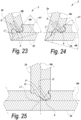
- FIG. 3 also shows the characteristic that said tongue 8 is cut free on one side.
- This cutting free of the tongue 8 took place by means of a narrow incision 15.
- the tongue 8 or the adjacent tongue portion 13, 14 can be rendered more elastic.
- the tongue 8 is cut free on only one side, here on the side of the tongue 8 which is situated closest to the formed outer corner 4.
- Said incision 15 further can be characterized by an axis line L4, which, seen in cross-section and in the longitudinal direction of the incision 15, follows the middle of this incision 15.
- this axis line is called the axis line of the incision L4 and is shown in dashed line in figure 3 .
- the axis line of the incision L4 also represents the direction of the incision.
- the orientation of the incision now can be characterized by an angle, herein denominated the incision angle H3, formed between said axis line of the incision L4 and the center line Ma, as represented in figure 3 .
- figure 3 also shows the characteristic, in accordance with the invention, that said groove 9, seen in cross-section, on the side situated closest to the outer corner 4, is bordered by a lip which extends to beyond said theoretical miter line L1, denominated the protruding lip 16.
- This offers, amongst others, the advantage that a contact surface 17 can be formed between the tongue 8 and the groove 9 beyond the theoretical miter line L1. It is clear that hereby, the embodiment of figure 3 forms an example of the invention.
- figure 3 shows the characteristic that on the side of the groove 9 which is situated closest to the formed inner corner 5, a small protruding lip portion 19 is provided wherein the panel surface 7b of the panel-shaped element having a groove 2b on the side of the formed inner corner 5, at the height of this inner corner 5, continues to beyond the theoretical miter line L1, as a result of which a contact surface 20 is formed there, which coincides with a portion of said panel surface 7b.
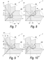
- figure 6 is shown how, seen in cross-section, the upper panel-shaped element 2d of the composed element of figure 1 , in a last step of the assembly, is coupled to the two upright panel-shaped elements 2a and 2c. This is performed by placing the groove 9 of the upper panel-shaped element 2d on one side, for example, the right-hand side, over the tongue 8 of the right-hand panel-shaped element 2c and subsequently placing the other groove 9 of the upper panel-shaped element 2d on the other side, in this example, the left-hand side, over the tongue 8 of the left panel-shaped element 2a.
- a locking tongue and groove connection 3 is shown, not according to the claimed invention, wherein the tongue 8 has a slit 12, which, seen in cross-section, globally extends according to a direction which deviates from the direction of the center line Ma of the panels-shaped element 2a on which the tongue is provided.
- FIG 9 a variant of the locking tongue and groove connection 3, not according to the claimed invention, is shown, with, in respect to the example of figure 8 , the additional preferred characteristic that the tongue is cut free on one side.
- This cutting free of the tongue 8 took place by means of a narrow incision 15.
- the tongue 8 or the adjacent tongue portion 13, 14 can be rendered more elastic. More particularly, the tongue 8 is cut free at one side only, here at the side of the tongue portion 13 which is situated closest to the formed outer corner 4.
- the incision 15 further is characterized by an incision angle H3, as represented in figure 9 .
- FIG 10 a variant of the locking tongue and groove connection, according to the claimed invention, is shown, with, in respect to the example of figure 9 , the characteristic according to the invention that the groove is bordered on one side by a lip 16 which extends to beyond said miter line.
- This lip is denominated the protruding lip 16. This offers the advantage that a contact surface 17 between the tongue 8 and the groove 9 can be formed beyond the theoretical miter line L1.
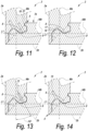
- FIG 11 a variant of the locking tongue and groove connection is shown, with, in respect to the example of figure 10 , the additional preferred characteristic that the panel surface 7b of the panel-shaped element 2b having the groove at the side of the formed inner corner 5, continues at the height of this inner corner 5 beyond the theoretical miter line L1, as a result of which at that location a contact surface 21 is formed, which coincides with a portion of said panel surface 7b.
- figure 15 an example is shown, wherein, as represented schematically, particle board is used, which comprises a basic layer with coarser particles, in other words, relatively coarse chips, and which, at least on one of the sides thereof, and in this case on both sides thereof, has an outer layer 22 with particles, which in respect to average fineness have a higher degree of fineness than the particles of said basic layer.
- the separation between the outer layer 22 with high density and the basic layer of the panel-shaped element is indicated in figure 15 by a separation line L5 in dash-dotted line.
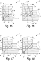
- Figure 21 shows a possible embodiment, according to the claimed invention, wherein the panel surface 6a of the panel-shaped element having the tongue, which is situated at the side of the formed outer corner, does not continue up to the formed outer corner 4, but up to a certain distance X therefrom. However, this distance X is smaller than half of the panel thickness Wb of the panel-shaped element with groove 2b to which it is coupled.
- Figure 22 shows a possible embodiment, wherein the panel-shaped elements, which are coupled to each other at an angle, have a different panel thickness. In this case, this is also called a non-perpendicular miter joint.
- the lower panel-shaped element 2b has a panel thickness Wb which is smaller than the panel thickness Wa of the left-hand panel-shaped element 2a to which it is coupled.
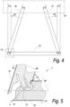
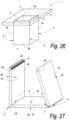
- Figure 26 also shows a practical application of the invention, more particularly a table 1, wherein a base is composed of four panel-shaped elements 2a, 2b, 2c and 2d, which are connected to each other at an angle by means of mitered corner connection 3 according to the invention.
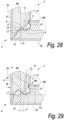
- Figure 28 shows an embodiment, not according to the claimed invention.
- this thus relates to a composed element, which comprises at least two panel-shaped elements 2a-2b, each with respective panel surfaces, wherein for each panel-shaped element a center line Ma-Mb is defined centrally between the two panel surfaces of that panel-shaped element;
- Figure 29 shows another particular variant, not according to the claimed invention.
- the tongue 8 consists of a split tongue, wherein the slit 12, globally seen and/or with the wall thereof which is situated closest to the inner corner, from the free end, in other words, open end thereof extends towards the bottom inclined towards the panel surface which is located at the inner corner 5, such as is clearly visible here by means of the inclined axis line L2.
- the flexibility of the tongue portion which comprises the locking element 10 can be adjusted in an easy manner by letting the slit end closer or less close to the respective panel surface.
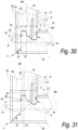
- Figure 30 represents a particular embodiment, not according to the claimed invention.
- the groove 9, at least at one side thereof, seen in cross-section, is bordered by a lip 16 which is located at least with a portion 29 thereof beyond said theoretical miter line L1, and this lip 16, in coupled condition, is located at the side of the tongue 8 which is situated closest to the formed outer corner 4, and this in such a manner that the aforementioned portion 29 provides at least a contact surface 17 for the tongue 8.
- a good lateral support is offered for the tongue.
- the protruding edge portion 31, next to its distal end 32, comprises a locking part 33, which, in coupled condition, engages behind the other panel-shaped element 2b, in such a manner that the relatively thin edge portion 31 is prevented from bending out due to warping.
- zone G1 does not exclude to apply identical profiles also outside of the zone G1.
- the zones G2 and G3 are made identical to each other as well, with the only difference that the portion being at 45 degrees, which is situated on the outer corner 4, extends somewhat longer. It is clear that then the same cutting tools and tool settings can be applied for the entire edge finishing.
- a “composed element” an element has to be understood which is already assembled, as well as such element which still is in disassembled condition. More particularly, this means that a piece of RTA furniture, which meets the invention and still is in disassembled condition, for example, packaged as a flat-pack piece of furniture, in this condition also has to be considered a “composed element”.
Landscapes
- Engineering & Computer Science (AREA)
- General Engineering & Computer Science (AREA)
- Mechanical Engineering (AREA)
- Life Sciences & Earth Sciences (AREA)
- Wood Science & Technology (AREA)
- Furniture Connections (AREA)
- Connection Of Plates (AREA)
- Finishing Walls (AREA)
Claims (15)
- Zusammengesetztes Element, welches zwei paneelförmige Elemente (2a, 2b) umfasst, wobei jedes Element jeweilige Paneeloberflächen (6a, 7a, 6b, 7b) besitzt; wobei für jedes der paneelförmige Elemente (2a, 2b), eine Mittellinie (Ma, Mb) in einer zentralen Position zwischen den zwei Oberflächen des Paneels (6a und 7a, 6b und 7b) dieses paneelförmigen Elements (2a, 2b), definiert ist;wobei die oben genannten paneelförmigen Elemente (2a, 2b), die eine Konfiguration in Form eines Paneels besitzen, aus einem Holzmaterial gebildet sind;wobei die oben genannten paneelförmigen Elemente (2a, 2b), so konfiguriert sind, dass sie mittels einer Verriegelungsverbindung (3) in Form einer Feder und einer Nut unter einem Winkel aneinander gekoppelt werden können und dadurch jeweils eine Verbindung, eine innere Ecke (5) und eine äußere Ecke (4) bilden; wobei die innere Ecke (5) und die äußere Ecke (4) eine theoretische Gehrungslinie (L1) definieren;wobei die oben genannte Verriegelungsverbindung (3) in Form einer Feder und einer Nut jeweils aus einer Feder (8) an einem der oben genannten paneelförmigen Elemente (2a), aus einer Nut (9) an dem anderen der oben genannten paneelförmigen Elemente (2b), und aus Verriegelungselementen (10, 11), die an der oben genannten Feder (8) und Nut (9) vorgesehen sind, gebildet ist;wobei die paneelförmigen Elemente (2a, 2b), so konfiguriert sind, dass sie in der seitlichen Richtung und unter einem Winkel mittels einer Drehbewegung und/oder einer Schnappbewegung miteinander gekoppelt werden können, um die oben genannte Verbindung zu erzielen;wobei, wenn man von einer Querschnittansicht aus betrachtet, die Oberfläche des Paneels (6a, 6b) jedes der beiden paneelförmigen Elemente (2a, 2b), an der ausgebildeten äußeren Ecke (4) in der Verbindung, sich mindestens bis zu der Mittellinie (Mb, Ma) des paneelförmigen Elements (2a, 2b) erstreckt, mit dem sie gekoppelt ist;wobei die oben genannten Verriegelungselemente (10, 11) nur auf der Höhe einer Seite der Feder (8) vorhanden sind;wobei die oben genannte Feder (8) auf mindestens einer Seite oder mittels eines schmalen Einschnitts (15) ausgeschnitten ist; wobei mit "schmalem Einschnitt" ein Einschnitt gemeint ist, dessen Tiefe größer als die Breite ist; wobei mit "ausgeschnitten" ein Ausschneiden durch Entfernen von noch vorhandenem Umgebungsmaterial des jeweiligen paneelförmigen Elements, gemeint ist;wobei die oben genannte Nut (9) an mindestens einer ihrer Seiten, wenn man von einer Querschnittansicht aus betrachtet, durch eine vorstehende Lippe (16) begrenzt ist, die sich über die oben genannte theoretische Gehrungslinie (L1) hinaus erstreckt, wenn man von dem paneelförmigen Element (2b), das die Nut (9) umfasst, aus betrachtet;wobei die oben genannte vorstehende Lippe (16) an der Seite angebracht ist, die der ausgebildeten äußeren Ecke (4) am nächsten liegt;wobei auf der Höhe dieser vorstehenden Lippe (16) mindestens eine Kontaktfläche (17, 18) zwischen der Feder (8) und der Nut (9) gebildet wird.
- Zusammengesetztes Element nach Anspruch 1, dadurch gekennzeichnet, dass die oben genannte Feder (8) in einer exzentrischen Position in Bezug auf den Mittelpunkt (S1) der theoretischen Gehrungslinie (L1) angebracht ist.
- Zusammengesetztes Element nach Anspruch 1 oder 2, dadurch gekennzeichnet, dass die oben genannten Verriegelungselemente (10, 11) nur in der Höhe an der Seite der Feder (8) vorhanden sind, die der inneren Ecke (5) am nächsten liegt.
- Zusammengesetztes Element nach einem der vorhergehenden Ansprüche, dadurch gekennzeichnet, dass die oben genannte Feder (8) nur auf einer Seite, vorzugsweise auf der Seite der Feder (8), die der äußeren Ecke (4) am nächsten liegt, eingeschnitten ist, wobei ein eventueller kleinerer Einschnitt auf der Höhe der inneren Ecke (5) unberücksichtigt bleibt.
- Zusammengesetztes Element nach einem der vorhergehenden Ansprüche, dadurch gekennzeichnet, dass die Feder (8) und Nut (9) ein solches Profil besitzen, dass sie in eine stabile Zwischenposition gebracht werden können, die sich vom endgültigen gekoppelten Zustand unterscheidet.
- Zusammengesetztes Element nach einem der vorhergehenden Ansprüche, dadurch gekennzeichnet, dass das zusammengesetzte Element (1) einen oder mehrere Einschnitte umfasst, zum Beispiel in der Form eines Schlitzes (12) in der Feder oder in der Form des Einschnitts (15), der oben erwähnt wurde, auf einer Seite der Feder; wobei mindestens einer der oben genannten Einschnitte (12, 15) teilweise oder vollständig mit einem elastisch verformbaren Material (25) gefüllt ist.
- Zusammengesetztes Element nach einem der vorhergehenden Ansprüche, dadurch gekennzeichnet, dass, wenn man von einer Querschnittansicht aus betrachtet, die Oberfläche des Paneels (6a, 6b) jedes paneelförmigen Elements (2a, 2b), an der Seite der ausgebildeten äußeren Ecke (4) sich bis zu einem Abstand erstreckt, der weniger als 1/4 der Dicke des Paneels (Wb, Wa) des paneelförmigen Elements (2a, 2b), mit dem sie gekoppelt ist, weiter bevorzugt bis zu einem Abstand, der weniger als 1/6 der Dicke des Paneels (Wb, Wa) des paneelförmigen Elements (2a, 2b), mit dem sie gekoppelt ist, beträgt, und vorzugsweise bis zu der äußeren Ecke (4).
- Zusammengesetztes Element nach einem der vorhergehenden Ansprüche, dadurch gekennzeichnet, dass das zusammengesetzte Element (1) auf der Höhe einer oder mehrerer der oben genannten ausgebildeten inneren Ecken (5) oder äußeren Ecken (4) ein separat vorgesehenes, als Ecke dienendes Element (24) aufnehmen kann.
- Zusammengesetztes Element nach einem der vorhergehenden Ansprüche, dadurch gekennzeichnet, dass die Oberfläche des Paneels (7b) des paneelförmigen Elements (2b), das eine Nut (9) an der Seite der ausgebildeten inneren Ecke (5) besitzt, sich auf der Höhe dieser inneren Ecke (5) bis über die theoretische Gehrungslinie (L1) hinaus fortsetzt, wodurch dort eine Kontaktfläche (21) gebildet wird, die mit einem Abschnitt der Oberfläche des Paneels (7b) übereinstimmt.
- Zusammengesetztes Element nach einem der vorhergehenden Ansprüche, dadurch gekennzeichnet, dass, anstatt zu bewirken, dass die Oberfläche des Paneels (6a, 6b) jedes paneelförmigen Elements (2a, 2b), wenn man von einer Querschnittansicht aus betrachtet, sich an der Seite der ausgebildeten äußeren Ecke (4) mindestens bis zu der Mittellinie (Ma, Mb) des paneelförmigen Elements (2a, 2b), erstreckt, wenn man von einer Querschnittansicht aus betrachtet, die Oberfläche des Paneels (6a, 6b) jedes paneelförmigen Elements (2a, 2b), an der Seite der ausgebildeten äußeren Ecke (4), sich bis zu einem Abstand von der ausgebildeten äußeren Ecke (4) erstreckt, der weniger als 3/4 der Dicke des Paneels (Wa, Wb) des paneelförmigen Elements (2a, 2b), mit dem sie gekoppelt ist, beträgt.
- Zusammengesetztes Element nach einem der vorhergehenden Ansprüche, wobei die oben genannte Nut (9) auf mindestens einer ihrer Seiten, wenn man von einer Querschnittansicht aus betrachtet, durch eine Lippe (16) begrenzt ist, die zumindest mit einem Abschnitt (29) davon jenseits der oben genannten theoretischen Gehrungslinie (L1) liegt; und wobei die oben genannte Lippe (16) im gekoppelten Zustand an der Seite der Feder (8) angebracht ist, die der ausgebildeten äußeren Ecke (4) am nächsten liegt; wobei der oben genannte Abschnitt mindestens eine Kontaktfläche (17) für die Feder (8) bereitstellt.
- Zusammengesetztes Element nach Anspruch 11, dadurch gekennzeichnet, dass die Lippe ein distales Ende (30) besitzt, das sich zu der Ebene des paneelförmigen Elements, erstreckt, in welcher die Nut vorgesehen ist, und das an der inneren Ecke angebracht ist und vorzugsweise durch einen Teil der Innenwand des paneelförmigen Elements, gebildet wird.
- Zusammengesetztes Element nach Anspruch 11 oder 12, dadurch gekennzeichnet, dass das Paneel, das mit der Feder (8) versehen ist, einen vorstehenden Kantenabschnitt (31) besitzt, der auf der Außenseite eine Verlängerung der Oberfläche des Paneels bildet und auf der Innenseite gegenüber dem Abschnitt (29) der Lippe (16) liegt und vorzugsweise an diesen angrenzt; wobei dieser vorstehende Kantenabschnitt sich mindestens bis zu der Mittellinie (Mb) des paneelförmigen Elements, das die Nut (9) umfasst, und vorzugsweise bis zu der eigentlichen äußeren Ecke erstreckt.
- Zusammengesetztes Element nach einem der vorhergehenden Ansprüche, wobei die Feder (8) aus einer geschlitzten Feder besteht, die einen Schlitz (12) umfasst, der sich, wenn man von einer Querschnittansicht aus betrachtet, im Allgemeinen in einer Richtung erstreckt, die von der Richtung der Mittellinie (MPa) des Elements abweicht, das eine Konfiguration in Form eines Paneels besitzt, an der die Feder (8) vorgesehen ist; dadurch gekennzeichnet, dass sich der Schlitz (12) in einer Gesamtansicht und/oder in einer Ansicht, in der seine Wand am nächsten zu der inneren Ecke liegt, von seinem freien Ende in Richtung der Basis erstreckt, die in Richtung der Oberfläche des Paneels geneigt ist, die sich an der inneren Ecke befindet.
- Zusammengesetztes Element nach einem der vorhergehenden Ansprüche, dadurch gekennzeichnet, dass es sich auf ein Möbelstück oder einen Teil eines Möbelstücks bezieht.
Applications Claiming Priority (2)
| Application Number | Priority Date | Filing Date | Title |
|---|---|---|---|
| BE2012/0079A BE1020495A4 (nl) | 2012-02-08 | 2012-02-08 | Samengesteld element en hoekverbinding hierbij toegepast. |
| PCT/IB2013/051018 WO2013118075A1 (en) | 2012-02-08 | 2013-02-07 | Composed element and corner connection applied herewith |
Publications (2)
| Publication Number | Publication Date |
|---|---|
| EP2811862A1 EP2811862A1 (de) | 2014-12-17 |
| EP2811862B1 true EP2811862B1 (de) | 2025-04-09 |
Family
ID=48044958
Family Applications (1)
| Application Number | Title | Priority Date | Filing Date |
|---|---|---|---|
| EP13713518.2A Active EP2811862B1 (de) | 2012-02-08 | 2013-02-07 | Zusammengesetztes element und damit ausgestattete eckverbindung |
Country Status (4)
| Country | Link |
|---|---|
| US (4) | US10104960B2 (de) |
| EP (1) | EP2811862B1 (de) |
| BE (1) | BE1020495A4 (de) |
| WO (1) | WO2013118075A1 (de) |
Families Citing this family (51)
| Publication number | Priority date | Publication date | Assignee | Title |
|---|---|---|---|---|
| BE1019891A5 (nl) * | 2011-03-28 | 2013-02-05 | Unilin Bvba | Samengesteld element en rugwandconstructie hierbij toegepast. |
| UA109938C2 (uk) * | 2011-05-06 | 2015-10-26 | Механічна фіксуюча система для будівельних панелей | |
| EP3967889B1 (de) | 2013-09-16 | 2025-08-13 | Välinge Innovation AB | Montiertes produkt |
| US9726210B2 (en) | 2013-09-16 | 2017-08-08 | Valinge Innovation Ab | Assembled product and a method of assembling the product |
| TR201907084T4 (tr) * | 2014-01-10 | 2019-06-21 | Vaelinge Innovation Ab | Bir ürünün monte edilmesine yönelik yöntem. |
| US9714672B2 (en) | 2014-01-10 | 2017-07-25 | Valinge Innovation Ab | Panels comprising a mechanical locking device and an assembled product comprising the panels |
| CN105873475A (zh) | 2014-01-10 | 2016-08-17 | 瓦林格创新股份有限公司 | 家具面板 |
| DE202014011293U1 (de) | 2014-02-10 | 2019-02-01 | Heinrich Ebbinghaus | Stützeinheit für Möbel |
| DE102014101600B4 (de) | 2014-02-10 | 2019-03-28 | Heinrich Ebbinghaus | Profilierung und Stützeinheit für Möbel |
| DE202014011271U1 (de) | 2014-02-10 | 2018-12-10 | Heinrich Ebbinghaus | Profilierung für Möbel |
| CA2946997C (en) | 2014-05-09 | 2022-08-16 | Valinge Innovation Ab | Mechanical locking system for building panels |
| UA119565C2 (uk) | 2014-07-11 | 2019-07-10 | Велінге Інновейшн Аб | Панель з напрямною |
| DE102014110123B4 (de) * | 2014-07-18 | 2025-04-24 | Guido Schulte | Eckverbindung zweier Bauelemente mit Spalt |
| DE102014110124A1 (de) * | 2014-07-18 | 2016-01-21 | Guido Schulte | Nut- und Federeckverbindung von zwei Bauelementen unter Eingliederung einer zusätzlichen Nut- und Federsteckverbindung |
| USD746590S1 (en) * | 2014-10-08 | 2016-01-05 | Wax Stacks, Llc | Collapsible storage box |
| BE1022567B1 (nl) * | 2014-10-31 | 2016-06-07 | Unilin Bvba | Meubel |
| LT3234380T (lt) | 2014-12-19 | 2019-11-11 | Vaelinge Innovation Ab | Plokštės su mechaninio fiksavimo įtaisu |
| CN107529898B (zh) | 2015-04-21 | 2021-04-27 | 瓦林格创新股份有限公司 | 包括镶板和滑动件的组件 |
| CA2983111A1 (en) | 2015-04-30 | 2016-11-03 | Valinge Innovation Ab | Panel with a fastening device |
| PL3353429T3 (pl) | 2015-09-22 | 2024-04-29 | Välinge Innovation AB | Zestaw paneli zawierający mechaniczne urządzenie blokujące i sposób demontażu wspomnianych paneli |
| PL3384165T3 (pl) | 2015-12-03 | 2022-01-03 | Välinge Innovation AB | Zestaw paneli zawierający mechaniczne urządzenie blokujące |
| DK3407765T3 (da) | 2016-01-26 | 2021-04-26 | Vaelinge Innovation Ab | Paneler omfattende en mekanisk fastlåsningsindretning til opnåelse af et møbelprodukt |
| PL3411599T3 (pl) | 2016-02-04 | 2021-08-09 | Välinge Innovation AB | Zestaw paneli do zmontowanego produktu |
| EP3414462B1 (de) | 2016-02-09 | 2020-10-07 | Välinge Innovation AB | Element und verfahren zur bereitstellung einer demontagenut |
| US10415613B2 (en) | 2016-02-09 | 2019-09-17 | Valinge Innovation Ab | Set of panel-shaped elements for a composed element |
| JP6921834B2 (ja) | 2016-02-15 | 2021-08-18 | ベーリンゲ、イノベイション、アクチボラグVaelinge Innovation Ab | 家具製品用のパネルの形成方法 |
| US9826828B1 (en) * | 2016-08-01 | 2017-11-28 | David E. Vaughan, Jr. | Cabinet assembly system utilizing cooperating grooved components |
| US10724564B2 (en) | 2016-10-27 | 2020-07-28 | Valinge Innovation Ab | Set of panels with a mechanical locking device |
| WO2018212701A1 (en) | 2017-05-15 | 2018-11-22 | Välinge Innovation AB | Elements and a locking device for an assembled product |
| GB2567447A (en) | 2017-10-11 | 2019-04-17 | Catemario Di Quadri Francesco | Furniture Item |
| LT3728870T (lt) | 2017-12-22 | 2023-08-10 | Välinge Innovation AB | Plokščių rinkinys |
| PL3728869T3 (pl) | 2017-12-22 | 2023-03-20 | Välinge Innovation AB | Zestaw paneli, sposób jego montażu i urządzenie blokujące do wyrobu meblowego |
| US10895276B2 (en) * | 2018-02-20 | 2021-01-19 | Dana Automotive Systems Group, Llc | Two material joint design |
| EP3768981B1 (de) * | 2018-03-23 | 2023-09-27 | Välinge Innovation AB | Plattenset |
| CN112262266B (zh) | 2018-04-18 | 2022-06-17 | 瓦林格创新股份有限公司 | 具有机械锁定装置的镶板组 |
| PL3781823T3 (pl) | 2018-04-18 | 2024-06-10 | Välinge Innovation AB | Zestaw paneli z mechanicznym urządzeniem blokującym |
| MY204415A (en) | 2018-04-18 | 2024-08-28 | Vlinge Innovation Ab | Symmetric tongue & t-cross |
| CA3096995A1 (en) | 2018-04-18 | 2019-10-24 | Valinge Innovation Ab | Set of panels with a mechanical locking device |
| US11614114B2 (en) | 2018-04-19 | 2023-03-28 | Valinge Innovation Ab | Panels for an assembled product |
| CN108835906A (zh) * | 2018-08-03 | 2018-11-20 | 合肥德懋家居有限公司 | 一种防止吧台裂缝的装置 |
| EP3844406A4 (de) * | 2018-08-30 | 2022-05-11 | Välinge Innovation AB | Satz aus platten mit mechanischer verriegelungsvorrichtung |
| EP4410151A3 (de) | 2018-08-30 | 2024-09-04 | Välinge Innovation AB | Satz von platten mit einer mechanischen verriegelungsvorrichtung |
| CN109853356A (zh) * | 2018-12-25 | 2019-06-07 | 浙江中隧桥波形钢腹板有限公司 | 快速装配式波形板构件、波形板快速组合箱及其装配方法 |
| AU2020214691B2 (en) * | 2019-01-29 | 2023-07-13 | Vilox Systems Ab | Joining system for furniture parts |
| EP3718437A1 (de) * | 2019-04-05 | 2020-10-07 | Välinge Innovation AB | Verfahren zur montage eines möbelstücks |
| EP3834661A1 (de) * | 2019-12-11 | 2021-06-16 | Välinge Innovation AB | Mechanisches arretierungssystem für platten |
| CN118076812A (zh) * | 2021-10-04 | 2024-05-24 | 瓦林格创新股份有限公司 | 镶板的机械连接布置结构 |
| IL291736A (en) * | 2022-03-27 | 2023-10-01 | Flooring Ind Ltd Sarl | A composite component and a corner connection applied with it |
| EP4500034A4 (de) * | 2022-03-30 | 2026-04-01 | Vaelinge Innovation Ab | Satz von paneelen und zugehöriger zusammengesetzter artikel |
| WO2024084324A1 (en) * | 2022-10-20 | 2024-04-25 | Unilin, Bv | Composed element and corner connection applied herewith. |
| US20240254768A1 (en) * | 2023-01-27 | 2024-08-01 | Välinge Innovation AB | Connection arrangement for panels |
Citations (3)
| Publication number | Priority date | Publication date | Assignee | Title |
|---|---|---|---|---|
| WO2010070605A2 (en) * | 2008-12-17 | 2010-06-24 | Unilin, Bvba | Composed element, multi-layered board and panel-shaped element for forming this composed element |
| WO2011151758A2 (en) * | 2010-06-03 | 2011-12-08 | Unilin, Bvba | Composed element and corner connection applied herewith |
| US20130071172A1 (en) * | 2010-06-03 | 2013-03-21 | Unilin, Bvba | Composed element |
Family Cites Families (8)
| Publication number | Priority date | Publication date | Assignee | Title |
|---|---|---|---|---|
| US1533099A (en) * | 1924-07-14 | 1925-04-14 | Robert E Carroll | Square-corner glue joint |
| US4099887A (en) * | 1977-07-18 | 1978-07-11 | Einhard Mackenroth | Structural joints |
| AT394252B (de) * | 1990-10-03 | 1992-02-25 | Katteneder Wolfgang | Gehrungsverbindung |
| US7454875B2 (en) * | 2004-10-22 | 2008-11-25 | Valinge Aluminium Ab | Mechanical locking system for floor panels |
| US7818939B2 (en) * | 2007-06-05 | 2010-10-26 | Irvin Bearinger | Snap lock joint |
| BE1019891A5 (nl) * | 2011-03-28 | 2013-02-05 | Unilin Bvba | Samengesteld element en rugwandconstructie hierbij toegepast. |
| UA109938C2 (uk) * | 2011-05-06 | 2015-10-26 | Механічна фіксуюча система для будівельних панелей | |
| WO2013121320A1 (en) * | 2012-02-13 | 2013-08-22 | Unilin, Bvba | Method for manufacturing a drawer |
-
2012
- 2012-02-08 BE BE2012/0079A patent/BE1020495A4/nl active
-
2013
- 2013-02-07 US US14/377,584 patent/US10104960B2/en not_active Expired - Fee Related
- 2013-02-07 EP EP13713518.2A patent/EP2811862B1/de active Active
- 2013-02-07 WO PCT/IB2013/051018 patent/WO2013118075A1/en not_active Ceased
-
2018
- 2018-10-19 US US16/165,156 patent/US10285499B2/en active Active
-
2019
- 2019-04-05 US US16/376,121 patent/US10524567B2/en active Active
- 2019-12-04 US US16/703,002 patent/US20200100585A1/en not_active Abandoned
Patent Citations (3)
| Publication number | Priority date | Publication date | Assignee | Title |
|---|---|---|---|---|
| WO2010070605A2 (en) * | 2008-12-17 | 2010-06-24 | Unilin, Bvba | Composed element, multi-layered board and panel-shaped element for forming this composed element |
| WO2011151758A2 (en) * | 2010-06-03 | 2011-12-08 | Unilin, Bvba | Composed element and corner connection applied herewith |
| US20130071172A1 (en) * | 2010-06-03 | 2013-03-21 | Unilin, Bvba | Composed element |
Also Published As
| Publication number | Publication date |
|---|---|
| US20190231066A1 (en) | 2019-08-01 |
| US10524567B2 (en) | 2020-01-07 |
| US10285499B2 (en) | 2019-05-14 |
| US20160000220A1 (en) | 2016-01-07 |
| US10104960B2 (en) | 2018-10-23 |
| US20190045921A1 (en) | 2019-02-14 |
| WO2013118075A1 (en) | 2013-08-15 |
| EP2811862A1 (de) | 2014-12-17 |
| BE1020495A4 (nl) | 2013-11-05 |
| US20200100585A1 (en) | 2020-04-02 |
Similar Documents
| Publication | Publication Date | Title |
|---|---|---|
| US10524567B2 (en) | Composed element and corner connection applied herewith | |
| CN102917616B (zh) | 组合元件和与之一起应用的转角连接 | |
| EP3594514B1 (de) | Platten mit mechanischer verriegelungseinrichtung | |
| EP2712518B1 (de) | Zusammengesetztes element | |
| AU2014376415B2 (en) | Panels comprising a mechanical locking device and an assembled product comprising the panels | |
| RU2580489C2 (ru) | Сборный элемент и используемое в нем угловое соединение | |
| EP1887910B1 (de) | Anordnung zwischen einem seitenglied und einer rückplatte eines möbelstücks | |
| KR101899170B1 (ko) | 조립된 요소 및 이것에 적용되는 코너 연결부 | |
| EP4252585B1 (de) | Zusammengesetztes element | |
| ITMI20110382U1 (it) | Elemento composto e raccordo angolare applicato con lo stesso |
Legal Events
| Date | Code | Title | Description |
|---|---|---|---|
| PUAI | Public reference made under article 153(3) epc to a published international application that has entered the european phase |
Free format text: ORIGINAL CODE: 0009012 |
|
| 17P | Request for examination filed |
Effective date: 20140729 |
|
| AK | Designated contracting states |
Kind code of ref document: A1 Designated state(s): AL AT BE BG CH CY CZ DE DK EE ES FI FR GB GR HR HU IE IS IT LI LT LU LV MC MK MT NL NO PL PT RO RS SE SI SK SM TR |
|
| AX | Request for extension of the european patent |
Extension state: BA ME |
|
| DAX | Request for extension of the european patent (deleted) | ||
| RIN1 | Information on inventor provided before grant (corrected) |
Inventor name: DEMAN, LUC Inventor name: DEVOS, PIETER Inventor name: MAERTENS, LUC |
|
| RIN1 | Information on inventor provided before grant (corrected) |
Inventor name: DEVOS, PIETER Inventor name: DEMAN, LUC Inventor name: MAERTENS, LUC |
|
| STAA | Information on the status of an ep patent application or granted ep patent |
Free format text: STATUS: EXAMINATION IS IN PROGRESS |
|
| 17Q | First examination report despatched |
Effective date: 20200821 |
|
| RAP1 | Party data changed (applicant data changed or rights of an application transferred) |
Owner name: UNILIN, BV |
|
| RAP1 | Party data changed (applicant data changed or rights of an application transferred) |
Owner name: FLOORING INDUSTRIES LIMITED, SARL |
|
| RAP1 | Party data changed (applicant data changed or rights of an application transferred) |
Owner name: UNILIN, BV |
|
| GRAP | Despatch of communication of intention to grant a patent |
Free format text: ORIGINAL CODE: EPIDOSNIGR1 |
|
| STAA | Information on the status of an ep patent application or granted ep patent |
Free format text: STATUS: GRANT OF PATENT IS INTENDED |
|
| GRAJ | Information related to disapproval of communication of intention to grant by the applicant or resumption of examination proceedings by the epo deleted |
Free format text: ORIGINAL CODE: EPIDOSDIGR1 |
|
| STAA | Information on the status of an ep patent application or granted ep patent |
Free format text: STATUS: EXAMINATION IS IN PROGRESS |
|
| GRAP | Despatch of communication of intention to grant a patent |
Free format text: ORIGINAL CODE: EPIDOSNIGR1 |
|
| STAA | Information on the status of an ep patent application or granted ep patent |
Free format text: STATUS: GRANT OF PATENT IS INTENDED |
|
| INTG | Intention to grant announced |
Effective date: 20241025 |
|
| INTC | Intention to grant announced (deleted) | ||
| INTG | Intention to grant announced |
Effective date: 20241115 |
|
| RIN1 | Information on inventor provided before grant (corrected) |
Inventor name: DEMAN, LUC Inventor name: MAERTENS, LUC Inventor name: DEVOS, PIETER |
|
| GRAS | Grant fee paid |
Free format text: ORIGINAL CODE: EPIDOSNIGR3 |
|
| GRAA | (expected) grant |
Free format text: ORIGINAL CODE: 0009210 |
|
| STAA | Information on the status of an ep patent application or granted ep patent |
Free format text: STATUS: THE PATENT HAS BEEN GRANTED |
|
| P01 | Opt-out of the competence of the unified patent court (upc) registered |
Free format text: CASE NUMBER: APP_7067/2025 Effective date: 20250211 |
|
| AK | Designated contracting states |
Kind code of ref document: B1 Designated state(s): AL AT BE BG CH CY CZ DE DK EE ES FI FR GB GR HR HU IE IS IT LI LT LU LV MC MK MT NL NO PL PT RO RS SE SI SK SM TR |
|
| REG | Reference to a national code |
Ref country code: GB Ref legal event code: FG4D |
|
| REG | Reference to a national code |
Ref country code: CH Ref legal event code: EP |
|
| REG | Reference to a national code |
Ref country code: DE Ref legal event code: R096 Ref document number: 602013086655 Country of ref document: DE |
|
| REG | Reference to a national code |
Ref country code: IE Ref legal event code: FG4D |
|
| REG | Reference to a national code |
Ref country code: NL Ref legal event code: MP Effective date: 20250409 |
|
| PG25 | Lapsed in a contracting state [announced via postgrant information from national office to epo] |
Ref country code: NL Free format text: LAPSE BECAUSE OF FAILURE TO SUBMIT A TRANSLATION OF THE DESCRIPTION OR TO PAY THE FEE WITHIN THE PRESCRIBED TIME-LIMIT Effective date: 20250409 |
|
| REG | Reference to a national code |
Ref country code: AT Ref legal event code: MK05 Ref document number: 1782707 Country of ref document: AT Kind code of ref document: T Effective date: 20250409 |
|
| PG25 | Lapsed in a contracting state [announced via postgrant information from national office to epo] |
Ref country code: FI Free format text: LAPSE BECAUSE OF FAILURE TO SUBMIT A TRANSLATION OF THE DESCRIPTION OR TO PAY THE FEE WITHIN THE PRESCRIBED TIME-LIMIT Effective date: 20250409 Ref country code: ES Free format text: LAPSE BECAUSE OF FAILURE TO SUBMIT A TRANSLATION OF THE DESCRIPTION OR TO PAY THE FEE WITHIN THE PRESCRIBED TIME-LIMIT Effective date: 20250409 Ref country code: PT Free format text: LAPSE BECAUSE OF FAILURE TO SUBMIT A TRANSLATION OF THE DESCRIPTION OR TO PAY THE FEE WITHIN THE PRESCRIBED TIME-LIMIT Effective date: 20250811 |
|
| REG | Reference to a national code |
Ref country code: LT Ref legal event code: MG9D |
|
| PG25 | Lapsed in a contracting state [announced via postgrant information from national office to epo] |
Ref country code: GR Free format text: LAPSE BECAUSE OF FAILURE TO SUBMIT A TRANSLATION OF THE DESCRIPTION OR TO PAY THE FEE WITHIN THE PRESCRIBED TIME-LIMIT Effective date: 20250710 Ref country code: NO Free format text: LAPSE BECAUSE OF FAILURE TO SUBMIT A TRANSLATION OF THE DESCRIPTION OR TO PAY THE FEE WITHIN THE PRESCRIBED TIME-LIMIT Effective date: 20250709 |
|
| PG25 | Lapsed in a contracting state [announced via postgrant information from national office to epo] |
Ref country code: PL Free format text: LAPSE BECAUSE OF FAILURE TO SUBMIT A TRANSLATION OF THE DESCRIPTION OR TO PAY THE FEE WITHIN THE PRESCRIBED TIME-LIMIT Effective date: 20250409 |
|
| PG25 | Lapsed in a contracting state [announced via postgrant information from national office to epo] |
Ref country code: BG Free format text: LAPSE BECAUSE OF FAILURE TO SUBMIT A TRANSLATION OF THE DESCRIPTION OR TO PAY THE FEE WITHIN THE PRESCRIBED TIME-LIMIT Effective date: 20250409 |
|
| PG25 | Lapsed in a contracting state [announced via postgrant information from national office to epo] |
Ref country code: HR Free format text: LAPSE BECAUSE OF FAILURE TO SUBMIT A TRANSLATION OF THE DESCRIPTION OR TO PAY THE FEE WITHIN THE PRESCRIBED TIME-LIMIT Effective date: 20250409 |
|
| PG25 | Lapsed in a contracting state [announced via postgrant information from national office to epo] |
Ref country code: AT Free format text: LAPSE BECAUSE OF FAILURE TO SUBMIT A TRANSLATION OF THE DESCRIPTION OR TO PAY THE FEE WITHIN THE PRESCRIBED TIME-LIMIT Effective date: 20250409 |
|
| PG25 | Lapsed in a contracting state [announced via postgrant information from national office to epo] |
Ref country code: RS Free format text: LAPSE BECAUSE OF FAILURE TO SUBMIT A TRANSLATION OF THE DESCRIPTION OR TO PAY THE FEE WITHIN THE PRESCRIBED TIME-LIMIT Effective date: 20250709 |
|
| PG25 | Lapsed in a contracting state [announced via postgrant information from national office to epo] |
Ref country code: IS Free format text: LAPSE BECAUSE OF FAILURE TO SUBMIT A TRANSLATION OF THE DESCRIPTION OR TO PAY THE FEE WITHIN THE PRESCRIBED TIME-LIMIT Effective date: 20250809 |
|
| PG25 | Lapsed in a contracting state [announced via postgrant information from national office to epo] |
Ref country code: LV Free format text: LAPSE BECAUSE OF FAILURE TO SUBMIT A TRANSLATION OF THE DESCRIPTION OR TO PAY THE FEE WITHIN THE PRESCRIBED TIME-LIMIT Effective date: 20250409 |
|
| REG | Reference to a national code |
Ref country code: DE Ref legal event code: R097 Ref document number: 602013086655 Country of ref document: DE |
|
| PG25 | Lapsed in a contracting state [announced via postgrant information from national office to epo] |
Ref country code: DK Free format text: LAPSE BECAUSE OF FAILURE TO SUBMIT A TRANSLATION OF THE DESCRIPTION OR TO PAY THE FEE WITHIN THE PRESCRIBED TIME-LIMIT Effective date: 20250409 Ref country code: SM Free format text: LAPSE BECAUSE OF FAILURE TO SUBMIT A TRANSLATION OF THE DESCRIPTION OR TO PAY THE FEE WITHIN THE PRESCRIBED TIME-LIMIT Effective date: 20250409 |
|
| PG25 | Lapsed in a contracting state [announced via postgrant information from national office to epo] |
Ref country code: CZ Free format text: LAPSE BECAUSE OF FAILURE TO SUBMIT A TRANSLATION OF THE DESCRIPTION OR TO PAY THE FEE WITHIN THE PRESCRIBED TIME-LIMIT Effective date: 20250409 |
|
| PG25 | Lapsed in a contracting state [announced via postgrant information from national office to epo] |
Ref country code: EE Free format text: LAPSE BECAUSE OF FAILURE TO SUBMIT A TRANSLATION OF THE DESCRIPTION OR TO PAY THE FEE WITHIN THE PRESCRIBED TIME-LIMIT Effective date: 20250409 |
|
| PG25 | Lapsed in a contracting state [announced via postgrant information from national office to epo] |
Ref country code: SK Free format text: LAPSE BECAUSE OF FAILURE TO SUBMIT A TRANSLATION OF THE DESCRIPTION OR TO PAY THE FEE WITHIN THE PRESCRIBED TIME-LIMIT Effective date: 20250409 Ref country code: RO Free format text: LAPSE BECAUSE OF FAILURE TO SUBMIT A TRANSLATION OF THE DESCRIPTION OR TO PAY THE FEE WITHIN THE PRESCRIBED TIME-LIMIT Effective date: 20250409 |
|
| PG25 | Lapsed in a contracting state [announced via postgrant information from national office to epo] |
Ref country code: IT Free format text: LAPSE BECAUSE OF FAILURE TO SUBMIT A TRANSLATION OF THE DESCRIPTION OR TO PAY THE FEE WITHIN THE PRESCRIBED TIME-LIMIT Effective date: 20250409 |
|
| PLBE | No opposition filed within time limit |
Free format text: ORIGINAL CODE: 0009261 |
|
| STAA | Information on the status of an ep patent application or granted ep patent |
Free format text: STATUS: NO OPPOSITION FILED WITHIN TIME LIMIT |
|
| REG | Reference to a national code |
Ref country code: CH Ref legal event code: L10 Free format text: ST27 STATUS EVENT CODE: U-0-0-L10-L00 (AS PROVIDED BY THE NATIONAL OFFICE) Effective date: 20260218 |
|
| 26N | No opposition filed |
Effective date: 20260112 |