EP2811729B1 - Durch Bilderzeugungsvorrichtung ohne zusätzliche Speichervorrichtung durchgeführter, scannerbetriebener Push-Betrieb - Google Patents
Durch Bilderzeugungsvorrichtung ohne zusätzliche Speichervorrichtung durchgeführter, scannerbetriebener Push-Betrieb Download PDFInfo
- Publication number
- EP2811729B1 EP2811729B1 EP13199579.7A EP13199579A EP2811729B1 EP 2811729 B1 EP2811729 B1 EP 2811729B1 EP 13199579 A EP13199579 A EP 13199579A EP 2811729 B1 EP2811729 B1 EP 2811729B1
- Authority
- EP
- European Patent Office
- Prior art keywords
- information processing
- processing apparatus
- image forming
- forming apparatus
- button
- Prior art date
- Legal status (The legal status is an assumption and is not a legal conclusion. Google has not performed a legal analysis and makes no representation as to the accuracy of the status listed.)
- Active
Links
Images



Classifications
-
- H—ELECTRICITY
- H04—ELECTRIC COMMUNICATION TECHNIQUE
- H04N—PICTORIAL COMMUNICATION, e.g. TELEVISION
- H04N1/00—Scanning, transmission or reproduction of documents or the like, e.g. facsimile transmission; Details thereof
- H04N1/00127—Connection or combination of a still picture apparatus with another apparatus, e.g. for storage, processing or transmission of still picture signals or of information associated with a still picture
- H04N1/00204—Connection or combination of a still picture apparatus with another apparatus, e.g. for storage, processing or transmission of still picture signals or of information associated with a still picture with a digital computer or a digital computer system, e.g. an internet server
- H04N1/00209—Transmitting or receiving image data, e.g. facsimile data, via a computer, e.g. using e-mail, a computer network, the internet, I-fax
- H04N1/00222—Transmitting or receiving image data, e.g. facsimile data, via a computer, e.g. using e-mail, a computer network, the internet, I-fax details of image data generation or reproduction, e.g. scan-to-email or network printing
- H04N1/00228—Image push arrangements, e.g. from an image reading device to a specific network destination
-
- H—ELECTRICITY
- H04—ELECTRIC COMMUNICATION TECHNIQUE
- H04N—PICTORIAL COMMUNICATION, e.g. TELEVISION
- H04N1/00—Scanning, transmission or reproduction of documents or the like, e.g. facsimile transmission; Details thereof
- H04N1/00127—Connection or combination of a still picture apparatus with another apparatus, e.g. for storage, processing or transmission of still picture signals or of information associated with a still picture
-
- H—ELECTRICITY
- H04—ELECTRIC COMMUNICATION TECHNIQUE
- H04N—PICTORIAL COMMUNICATION, e.g. TELEVISION
- H04N1/00—Scanning, transmission or reproduction of documents or the like, e.g. facsimile transmission; Details thereof
- H04N1/00127—Connection or combination of a still picture apparatus with another apparatus, e.g. for storage, processing or transmission of still picture signals or of information associated with a still picture
- H04N1/00204—Connection or combination of a still picture apparatus with another apparatus, e.g. for storage, processing or transmission of still picture signals or of information associated with a still picture with a digital computer or a digital computer system, e.g. an internet server
-
- H—ELECTRICITY
- H04—ELECTRIC COMMUNICATION TECHNIQUE
- H04N—PICTORIAL COMMUNICATION, e.g. TELEVISION
- H04N1/00—Scanning, transmission or reproduction of documents or the like, e.g. facsimile transmission; Details thereof
- H04N1/00127—Connection or combination of a still picture apparatus with another apparatus, e.g. for storage, processing or transmission of still picture signals or of information associated with a still picture
- H04N1/00204—Connection or combination of a still picture apparatus with another apparatus, e.g. for storage, processing or transmission of still picture signals or of information associated with a still picture with a digital computer or a digital computer system, e.g. an internet server
- H04N1/00209—Transmitting or receiving image data, e.g. facsimile data, via a computer, e.g. using e-mail, a computer network, the internet, I-fax
- H04N1/00222—Transmitting or receiving image data, e.g. facsimile data, via a computer, e.g. using e-mail, a computer network, the internet, I-fax details of image data generation or reproduction, e.g. scan-to-email or network printing
- H04N1/00225—Transmitting or receiving image data, e.g. facsimile data, via a computer, e.g. using e-mail, a computer network, the internet, I-fax details of image data generation or reproduction, e.g. scan-to-email or network printing details of image data generation, e.g. scan-to-email or network scanners
-
- H—ELECTRICITY
- H04—ELECTRIC COMMUNICATION TECHNIQUE
- H04N—PICTORIAL COMMUNICATION, e.g. TELEVISION
- H04N1/00—Scanning, transmission or reproduction of documents or the like, e.g. facsimile transmission; Details thereof
- H04N1/00127—Connection or combination of a still picture apparatus with another apparatus, e.g. for storage, processing or transmission of still picture signals or of information associated with a still picture
- H04N1/00204—Connection or combination of a still picture apparatus with another apparatus, e.g. for storage, processing or transmission of still picture signals or of information associated with a still picture with a digital computer or a digital computer system, e.g. an internet server
- H04N1/00236—Connection or combination of a still picture apparatus with another apparatus, e.g. for storage, processing or transmission of still picture signals or of information associated with a still picture with a digital computer or a digital computer system, e.g. an internet server using an image reading or reproducing device, e.g. a facsimile reader or printer, as a local input to or local output from a computer
-
- H—ELECTRICITY
- H04—ELECTRIC COMMUNICATION TECHNIQUE
- H04N—PICTORIAL COMMUNICATION, e.g. TELEVISION
- H04N1/00—Scanning, transmission or reproduction of documents or the like, e.g. facsimile transmission; Details thereof
- H04N1/0035—User-machine interface; Control console
- H04N1/00352—Input means
- H04N1/00384—Key input means, e.g. buttons or keypads
-
- H—ELECTRICITY
- H04—ELECTRIC COMMUNICATION TECHNIQUE
- H04N—PICTORIAL COMMUNICATION, e.g. TELEVISION
- H04N2201/00—Indexing scheme relating to scanning, transmission or reproduction of documents or the like, and to details thereof
- H04N2201/0008—Connection or combination of a still picture apparatus with another apparatus
- H04N2201/0013—Arrangements for the control of the connected apparatus by the still picture apparatus
-
- H—ELECTRICITY
- H04—ELECTRIC COMMUNICATION TECHNIQUE
- H04N—PICTORIAL COMMUNICATION, e.g. TELEVISION
- H04N2201/00—Indexing scheme relating to scanning, transmission or reproduction of documents or the like, and to details thereof
- H04N2201/0008—Connection or combination of a still picture apparatus with another apparatus
- H04N2201/0034—Details of the connection, e.g. connector, interface
- H04N2201/0037—Topological details of the connection
- H04N2201/0039—Connection via a network
-
- H—ELECTRICITY
- H04—ELECTRIC COMMUNICATION TECHNIQUE
- H04N—PICTORIAL COMMUNICATION, e.g. TELEVISION
- H04N2201/00—Indexing scheme relating to scanning, transmission or reproduction of documents or the like, and to details thereof
- H04N2201/0008—Connection or combination of a still picture apparatus with another apparatus
- H04N2201/0034—Details of the connection, e.g. connector, interface
- H04N2201/0037—Topological details of the connection
- H04N2201/0041—Point to point
-
- H—ELECTRICITY
- H04—ELECTRIC COMMUNICATION TECHNIQUE
- H04N—PICTORIAL COMMUNICATION, e.g. TELEVISION
- H04N2201/00—Indexing scheme relating to scanning, transmission or reproduction of documents or the like, and to details thereof
- H04N2201/0008—Connection or combination of a still picture apparatus with another apparatus
- H04N2201/0034—Details of the connection, e.g. connector, interface
- H04N2201/0048—Type of connection
- H04N2201/0049—By wire, cable or the like
-
- H—ELECTRICITY
- H04—ELECTRIC COMMUNICATION TECHNIQUE
- H04N—PICTORIAL COMMUNICATION, e.g. TELEVISION
- H04N2201/00—Indexing scheme relating to scanning, transmission or reproduction of documents or the like, and to details thereof
- H04N2201/0077—Types of the still picture apparatus
- H04N2201/0094—Multifunctional device, i.e. a device capable of all of reading, reproducing, copying, facsimile transception, file transception
Definitions
- the present disclosure generally relates to an image forming system, an image forming apparatus, and a transmission method for image data that realizes a scanner-driven push operation by the image forming apparatus having no auxiliary storage device.
- a typical image forming apparatus In response to the operation of a user, a typical image forming apparatus causes a scanner to read a document image, and stores image data from the scanned document image in a hard disk (HDD) serving as an auxiliary storage device.
- the typical image forming apparatus notifies a personal computer (PC) of preparation completion, and reads out the image data from the hard disk to a memory buffer and transmits the image data to the PC, in response to an image data request from the PC. Owing to this configuration, a scanner-driven push operation is performed.
- PC personal computer
- the image data read by the scanner-driven push operation is stored in a box (folder) within the HDD, and the image data is transmitted from the image forming apparatus to the PC.
- the present invention provides a system as defined in claim 1.
- the system may include the features of any one or more of dependent claims 2 to 5.
- the present invention also provides a method as defined in claim 6.
- the method may include the features of any one or more of dependent claims 7 to 9
- the present disclosure relates to an image forming system, an image forming apparatus, and a transmission method for image data that realizes a scanner-driven push operation by the image forming apparatus having no auxiliary storage device.
- a preferred image forming system of the present disclosure includes an image forming apparatus coupled to a network and an information processing apparatus coupled to the network.
- the image forming apparatus includes a button, a memory device, a scanner, and a first control unit.
- the first control unit is configured to perform a variety of functions.
- the first control unit is configured to store, in the memory device, an information processing apparatus identifier that is assigned to the button.
- the first control unit is also configured to transmit, to the information processing apparatus, press-down information that includes the information processing apparatus identifier corresponding to the button that is pressed-down, in response to a request for the press-down information of the button that is received from the information processing apparatus via the network.
- the first control unit is configured to read a document image set in the scanner, in response to a scan execution request that is received from the information processing apparatus via the network.
- the first control unit is configured to transmit image data of the document image to the information processing apparatus via the network. Additionally, the first control unit is additionally configured to reset the press-down information.
- the information processing apparatus includes an auxiliary storage device, a scanner driver, and a second control unit.
- the second control unit is configured to perform a variety of functions.
- the second control unit is configured to periodically transmit the request for press-down information to the image forming apparatus via the network.
- the second control unit is also configured to determine whether or not the information processing apparatus identifier in the press-down information received from the image forming apparatus matches an information processing apparatus identifier stored within the information processing apparatus.
- the second control unit is configured to transmit the scan execution request to the image forming apparatus via the scanner driver if the information processing apparatus identifier in the press-down information received from the image forming apparatus matches the information processing apparatus identifier stored within the information processing apparatus.
- the second control unit is configured to store, in the auxiliary storage device, image data that is received from the image forming apparatus via the scanner driver.
- one or more processors may execute one or more sets of programming instructions as at least part of carrying out one or more of the functions described herein.
- embodiment 1 describes in detail the claimed invention, and embodiment 2 describe examples not covered by the claims but helpful for understanding the invention.
- Fig. 1 is a schematic diagram illustrating the configuration of the image forming system 100 according to a first embodiment of the present disclosure.
- a plurality of information processing apparatuses for example, personal computers (PCs) 10-1 to 10-N, whose number is N, and an image forming apparatus 20 are coupled to a network 30.
- the image forming apparatus 20 is inexpensive, and has no auxiliary storage device.
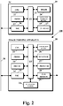
- Fig. 2 is a block diagram illustrating the hardware configurations of a PC 10 and the image forming apparatus 20 in the image forming system 100.
- the PC (information processing apparatus) 10 is a personal computer, and a central processing unit (CPU) 11 is coupled to a programmable read only memory (PROM) 13, a dynamic random access memory (DRAM) 14, an auxiliary storage device 15, a network interface (NIC) 16, and an input-output (I/O) device 17 through an interface 12.
- interface 12 may be any type of interface that may be used to allow communication among the CPU 11, the PROM 13, the DRAM 14, the NIC 16, and the I/O device 17.
- the PROM 13 is, for example, a flash memory device, and a basic input/output system (BIOS) is stored therein.
- BIOS basic input/output system
- the DRAM 14 is used as a main storage device.
- An operating system (OS) and various kinds of drivers and applications may be stored in the auxiliary storage device 15.
- a CPU 21 is coupled to a PROM 23, a DRAM 24, a network interface card (NIC) 25, an operation panel 26, a scanner 27, a printer 28, a facsimile (FAX) modem 29, and an auto sheet feeder 2A.
- interface 22 may be any type of interface that may be used to allow communication among the CPU 11, the PROM 13, the DRAM 14, the NIC 16, and the I/O device 17..
- the PROM 23 is, for example, a flash memory device, and may store therein a BIOS, an OS, various kinds of drivers, and various applications that run on the image forming apparatus.
- the DRAM 24 is used as a main storage device.
- the network interface 25 is coupled to the network 30.
- the scanner 27 is used for digitizing an image on a paper medium, and the file thereof may be used for printing, facsimile transmission, or file transmission.
- the printer 28 includes a print engine, a paper feeding unit, a transport unit, and a paper ejection unit, which perform various tasks to paper.
- Bitmap data stored on the DRAM 24 is provided to the printer 28, and the printer 28 forms an electrostatic latent image on a photoconductive drum on the basis of this data, develops the electrostatic latent image using toner, transfers and fixes a toner image to a sheet of paper, and ejects the sheet of paper.
- Fig. 3 is a block diagram illustrating the functional configuration relating to a scanner function of the image forming apparatus 20.
- a first control unit 40 includes a first scanner control unit 41 for the scanner 27 and the auto sheet feeder 2A, and a first button information control unit 42 for the operation panel 26 and a button information storage unit 230 within the PROM 23.
- the operation panel 26 includes buttons 261 to 263 used for indirectly starting push scan. Furthermore, the operation panel 26 includes an indicator 260 displaying the button name of a button pressed down from among the buttons 261 to 263.
- the button information storage unit 230 stores therein button information.
- the button information includes at least flags F1 to F3 indicating whether or not the buttons 261 to 263 have been pressed down, respectively, IP addresses IPA1 to IPA3 serving as PC identifiers assigned to the buttons 261 to 263, respectively, and button names (hereinafter, the button names of the buttons 261 to 263 are buttons 1 to 3, respectively) assigned to the buttons 261 to 263, respectively.
- the first button information control unit 42 refers to the button information storage unit 230, and causes the indicator 260 to display the button name, "button i", thereof and sets flag Fi within the button information storage unit 230.
- the first button information control unit 42 resets the flag Fi that is displayed in the indicator 260 and corresponds to the "button i" and clears the indicator 260.
- a first communication unit 43 includes the network interface 25 in Fig. 2 and a communication protocol stack for the OS.
- This communication protocol stack includes a TCP/IP unit and a UDP/IP unit.
- the first communication unit 43 individually sorts pieces of information received from a TCP/IP unit and a UDP/IP unit in the PC 10, into the first scanner control unit 41 and the first button information control unit 42.
- the TCP/IP unit in the first communication unit 43 receives a command from a Tool Without An Interesting Name (TWAIN) driver in the PC 10, and sends back the response thereto from the first scanner control unit 41 to the PC 10.
- the UDP/IP unit in the first communication unit 43 receives, from the PC 10, an acquisition request for the IP addresses IPA1 to IPA3 (the press-down information).
- the acquisition request is based on a Simple Network Management Protocol (SNMP), and sends back, to the PC 10, the button information from the first button information control unit 42, the button information corresponding to this request and being based on the SNMP.
- SNMP Simple Network Management Protocol
- the first scanner control unit 41 sets, for the scanner 27, an image reading condition such as resolution.
- the first scanner control unit 41 causes the auto sheet feeder 2A to be driven and feed a document, causes the scanner 27 to read and convert the image thereof into image data, and sends back the image data to a request source via the TCP/IP unit in the first communication unit 43.
- the first button information control unit 42 includes an SNMP agent on the first communication unit 43, and control programs on the operation panel 26 and the button information storage unit 230, which serve as processing targets.
- the button information storage unit 230 is a portion of a management information base (MIB).
- Fig. 4 is a block diagram illustrating the functional configuration relating to the scanner function of the PC 10.
- Blocks 150, 151, and 152 in Fig. 4 are stored within the auxiliary storage device 15 in Fig. 2 .
- Data held in the IP address storage unit 151 is data written into a specified leaf node of the registry of the OS at the time of a communication setting.
- the input-output (I/O) device 17 includes a display device 170 and an input device 171.
- the input device 171 includes, for example, a keyboard and a pointing device.
- a second control unit 50 includes a system control unit 51 controlling the units within PC 10, a second scanner control unit 52 controlling the image forming apparatus 20, a second button information control unit 53 controlling the button information of the image forming apparatus 20, and a transmission control unit 54 transmitting the image file of a scan result.
- the user interface (UI) unit 55 In response to an operation performed on the input device 171 by a user, the user interface (UI) unit 55 causes the display device 170 to display a menu relating to image scanning. In each menu, in response to an operation performed on the input device 171 by the user, the user interface unit 55 notifies the system control unit 51 of an instruction and a setting value (selection) which has been input. The system control unit 51 performs a process in accordance with a notification result.
- a second communication unit 56 includes the network interface 16 in Fig. 2 and a communication protocol stack for the OS.
- This communication protocol stack includes a TCP/IP unit and a UDP/IP unit.
- the second communication unit 56 individually sorts pieces of information received from the TCP/IP unit and the UDP/IP unit in the image forming apparatus 20, into a scanner driver 57 and the second button information control unit 53.
- the second communication unit 56 further includes the UDP/IP unit located above the TCP/IP unit so as to correspond to the transmission control unit 54, and receives a transmission request from the transmission control unit 54 using this UDP/IP unit.
- the second scanner control unit 52 transmits a scan execution request to the image forming apparatus 20 via the scanner driver 57 serving as the TWAIN driver, the TCP/IP unit in the second communication unit 56, and the network 30.
- the second button information control unit 53 includes an SNMP manager on the second communication unit 56, and a control program on the system control unit 51.
- Fig. 5 is a flowchart illustrating process performed by the UI unit 55 and the system control unit in the PC in response to the operation of the user before the PC causes the image forming apparatus to perform image scanning.
- the flowchart indicates a preset process performed by the user interface unit 55 and the system control unit 51 before the user presses down one of the buttons 261 to 263 in the image forming apparatus 20.
- a step S0 the user selects one 26i (i is one of 1 to 3) from among the buttons 261 to 263 in the PC 10 via the input device 171, the buttons 261 to 263 being displayed in the display device 170, and sets the name thereof.
- the user interface unit 55 notifies the system control unit 51 of this selection.
- the system control unit 51 specifies the identifier i and button name of this button 26i and an IP address within the IP address storage unit 151, and instructs the second button information control unit 53 to perform a button setting.
- the second button information control unit 53 transmits a button setting request accompanied with the button identifier i, the button name, and the IP address to the first button information control unit 42 via the second communication unit 56 and the first communication unit 43 in the image forming apparatus 20.
- the first button information control unit 42 overwrites and sets a button name within the button information storage unit 230 with "button i", the button name corresponding to the button identifier i, and overwrites and sets the IP address to an IP address IPAi.
- a step S1 the user operates the input device 171, selects a button name, and inputs the transmission destination address of the image file of a scan result.
- the user interface unit 55 notifies the system control unit 51 of this transmission destination address along with this button name.
- the system control unit 51 stores, in the destination address storage unit 152, this transmission destination address associated with the address of this button name.
- This transmission destination address includes a file transfer protocol such as a File Transfer Protocol (FTP), a Server Message Block (SMB), or a Simple Mail Transfer Protocol (SMTP).
- FTP File Transfer Protocol
- SMB Server Message Block
- SMTP Simple Mail Transfer Protocol
- the input of the transmission destination address may also be performed by specifying data within an address book 58.
- a step S2 the user operates the input device 171 and inputs the path of a folder within the auxiliary storage device 15.
- the folder then stores therein the image file of a scan result.
- the user interface unit 55 notifies the system control unit 51 of this input.
- the system control unit 51 generates the image file storage folder 150 of this path.
- the path of a scan image file storage folder may also be set with any button name.
- the processing operations in the steps S0 to S2 are selectively performed in response to an operation performed on the input device 171 by the user.
- one or more buttons are set.
- a timer 59 includes a hardware timer within the CPU 11 in Fig. 2 , which is utilized by a software interval timer of the OS. Every time five seconds has elapsed, for example, the timer 59 causes a time-up event to occur for the system control unit 51. In response to this, the system control unit 51 instructs the second button information control unit 53 to acquire the button information. In response to this instruction, via the second communication unit 56 and the network 30, the second button information control unit 53 requests the first button information control unit 42 in the image forming apparatus 20 to acquire the button information. The timer 59 is activated at the time of the activation of the second control unit 50, and halted at the time of the termination of the second control unit 50.
- Fig. 6 is a flowchart illustrating process performed by the system control unit 51 in the PC 10 and started in response to the occurrence of a time-up event.
- a step S10 the system control unit 51 invalidates the timer 59, and suppresses the occurrence of a time-up event.
- step S11 via the second button information control unit 53, the system control unit 51 instructs the second button information control unit 53 to acquire the button information.
- the second button information control unit 53 repeats processing operations ranging from a step S13 to a step S16 until affirmative determination is performed in the step S15.
- step S14 it is determined whether or not a button has been pressed down.
- the second button information control unit 53 returns control to the system control unit 51, and via the second scanner control unit 52, the system control unit 51 requests the first scanner control unit 41 in the image forming apparatus 20 to confirm whether or not a document is placed on the auto sheet feeder 2A and the scanner 27 is in a ready state.
- the first scanner control unit 41 confirms whether or not the scanner 27 is in a ready state and a sensor has detected that a document is placed on the auto sheet feeder 2A, and the first scanner control unit 41 sends back the result to the system control unit 51 via the second scanner control unit 52.
- step S18 if this response indicates that it is possible to scan, the system control unit 51 proceeds to a step S19, and if this is not the case, the system control unit 51 returns to the step S17.
- this loop processing operation in the steps S17 and S18 is performed periodically, for example, every one second.
- step S19 via the second scanner control unit 52 and the scanner driver 57, the first scanner control unit 41 in the image forming apparatus 20 is requested to execute scan.
- the first scanner control unit 41 causes the auto sheet feeder 2A to be driven to feed a document, and causes the scanner 27 to read and convert the scanned image into image data.
- the first scanner control unit 41 causes the image data to be stored in a buffer area within the DRAM 24, and sends back the image data to the second scanner control unit 52 in units of pages or in units of blocks into which a page is divided, in accordance with a buffer size.
- the image data is stored in a buffer area within the DRAM 14.
- the first scanner control unit 41 When image scanning for all pages has been completed or when the user has pressed down a scan termination button on the operation panel 26 (not illustrated) the first scanner control unit 41 resets the flag Fi corresponding to the button name, "button i", displayed in the indicator 260, and clears the display of the button name. The first scanner control unit 41 causes an image scanning completion event to occur for the second scanner control unit 52, which in turn notifies the system control unit 51 that image scanning has completed.
- a step S20 the timer 59 is validated, the suppression of the occurrence of the time-up event is cancelled, and the process is returned.
- Fig. 7 is a flowchart illustrating process performed in the system control unit 51 in the PC 10 and started in response to the notice of a scan completion event.
- a step S30 the system control unit 51 causes the image data in the buffer area to be stored in the image file storage folder 150, as a file.
- a step S31 the system control unit 51 reads a destination address corresponding to the button name, "button i", within the destination address storage unit 152.
- a step S32 if this destination address exists (alternatively, if the destination address exists and the necessity of transmitting has been checked), the system control unit 51 specifies the path of the file and the destination address thereof for the transmission control unit 54, and instructs the transmission control unit 54 to perform transmission.
- the transmission control unit 54 transmits this image file to the destination address via the second communication unit 56, in accordance with a protocol indicated by a protocol unit at the destination address.
- a transmission time may be set with respect to each button name, and transmission may also be performed by waiting for a transmission time corresponding to a button name.
- the PC 10 transmits a scan execution request to the image forming apparatus 20 via the scanner driver 57. Since the auxiliary storage device 15 in the PC 10 is caused to store therein image data received from the image forming apparatus 20 via the scanner driver 57, even if the image forming apparatus 20 includes no auxiliary storage device, it may become possible to realize the same scanner-driven push operation as if the image forming apparatus 20 includes an auxiliary storage device.
- the image forming apparatus 20 includes no auxiliary storage device, it may become possible to realize the automatic transfer of the image file of a scan result to a transmission destination preliminarily set with respect to each button, in the same way as when the image forming apparatus 20 includes an auxiliary storage device.
- the user may be possible for the user to set, from the PC 10 via the network 30, an association between the buttons 261 to 263 in the image forming apparatus 20 and the PC 10. Therefore, even if the function of the image forming apparatus is enhanced, it may be possible to further simplify the configuration of the image forming apparatus and achieve price reduction.
- Fig. 8 is a block diagram illustrating the functional configuration relating to the scanner function of an image forming apparatus 20A, according to a second embodiment of the present disclosure.
- a button information storage unit 230A is included where the flags F1 to F3 are omitted from the button information storage unit 230 in Fig. 3 , and a pressed-down button information storage unit 240 is included within the DRAM 24.
- the initial value of the pressed-down button information storage unit 240 is NULL or empty.
- a first button information control unit 42A copies an IP address IPAi within the button information storage unit 230A onto the pressed-down button information storage unit 240.
- the other configuration elements of the image forming apparatus 20A and the functions thereof are the same as the configuration elements of the image forming apparatus 20 in the first embodiment and the functions thereof
- Fig. 9 is a flowchart illustrating process performed in the system control unit in the PC 10 and started in response to the occurrence of the time-up event, according to the second embodiment of the present disclosure.
- the first button information control unit 42A In response to a press-down information acquisition request from the PC 10 in a step S11, the first button information control unit 42A sends back the IP address IPAi in the pressed-down button information storage unit 240.
- a step S15 if the IP address IPAi coincides with the IP address IPA of the PC 10, the button information control unit 53 proceeds to a step S17, and if this is not the case, the button information control unit 53 proceeds to a step S20.
- the first button information control unit 42A clears the display of the indicator 260, and clears the content of the pressed-down button information storage unit 240 (NULL or empty).
- processing operations in the first button information control unit 42A and the scanner driver 57 become easier than in the processing operations in the first embodiment.
- the steps S17 and S18 when the steps S17 and S18 are omitted, the time-up interval of the timer T is shortened, the flags F1 to F3 are not used, and the image forming apparatus 20 or 20A has received the press-down information acquisition request, it may also be directly detected which of the buttons 261 to 263 is pressed down.
- IP addresses IPA1 to IPA3 illustrated in Fig. 3 or Fig. 8 and the IP address storage unit 151 in Fig. 4 may also adopt configurations in which unique device IDs (UDIDs) are used in place of the IP addresses.
- UDIDs unique device IDs
- the scanner driver 57, the first communication unit 43, and the second communication unit 56 are not limited to the protocols described in the first embodiment, and may also adopt configurations in which another protocol is used.
Landscapes
- Engineering & Computer Science (AREA)
- General Engineering & Computer Science (AREA)
- Multimedia (AREA)
- Signal Processing (AREA)
- Computing Systems (AREA)
- Facsimiles In General (AREA)
- Control Or Security For Electrophotography (AREA)
Claims (9)
- Ein Bilderzeugung System (100) aufweisend:eine Bilderzeugung Vorrichtung (20), gekoppelt mit einem Netzwerk (30), wobei die Bilderzeugung Vorrichtung (20) umfasst eine Taste (261), eine Speichervorrichtung (23), einen Scanner (27) und eine erste Steuereinheit (40); undeine Informationsverarbeitung Vorrichtung (10), gekoppelt mit dem Netzwerk, wobeidie Informationsverarbeitung Vorrichtung umfasst eine Hilfsspeicher Vorrichtung (15), eine Übertragung Zieladresse Einstellung Einheit, einen Tool Without An Interesting Name (TWAIN) Treiber, der als ein Scanner Treiber (57) fungiert, und eine zweite Steuereinheit (50); wobeidie erste Steuereinheit konfiguriert ist zumi) Speichern, in der Speichervorrichtung, einen Informationsverarbeitung Vorrichtung Identifizierer, der der Taste zugeordnet ist,ii) Übertragen, zu der Informationsverarbeitung Vorrichtung, eine Herunterdrücken Information, wobei
die Herunterdrücken Information umfasst den Informationsverarbeitung Vorrichtung Identifizierer, korrespondierend mit der Taste, als Antwort auf eine Anfrage für die Herunterdrücken Information der Taste, die empfangen ist von der Informationsverarbeitung Vorrichtung via das Netzwerk,iii) Lesen eines Dokumentbilds gesetzt im Scanner als Antwort auf eine Scan Ausführungsanfrage, die empfangen ist von der Informationsverarbeitung Vorrichtung via das Netzwerk unter Verwendung des TWAIN Treibers in der Informationsverarbeitung Vorrichtung,iv) Übertragen von Bilddaten des Dokumentbildes an die Informationsverarbeitung Vorrichtung via das Netzwerk unter Verwendung des TWAIN-Treibers, undv) Zurücksetzen der Herunterdrücken Information;
wobei die Übertragung Zieladresse Einstellung Einheit konfiguriert ist zum Speichern, in der Hilfsspeicher Vorrichtung, eine Übertragung Zieladresse korrespondierend mit der Taste; und wobeidie zweite Steuereinheit konfiguriert ist zumi) periodischen Übertragen der Anfrage für eine Herunterdrück Information zu der Bilderzeugung Vorrichtung via das Netzwerk,ii) Bestimmen, ob oder ob nicht der Informationsverarbeitung Vorrichtung Identifizierer in der Herunterdrück Information, empfangen von der Bilderzeugung Vorrichtung, zusammenpasst mit einem Informationsverarbeitung Vorrichtung Identifizierer, gespeichert in der Informationsverarbeitung Vorrichtung,iii) Übertragen der Scan Ausführanfrage zu der Bilderzeugung Vorrichtung via das Netzwerk unter Verwendung des TWAIN-Treibers, wenn der Informationsverarbeitung Vorrichtung Identifizierer in der Herunterdrücken Information, empfangen von der Bilderzeugung Vorrichtung, zusammenpasst mit dem Informationsverarbeitung Vorrichtung Identifizierer, gespeichert in der Informationsverarbeitung Vorrichtung,iv) Speichern, in der Hilfsspeicher Vorrichtung, Bilddaten, die empfangen sind von der Bilderzeugung Vorrichtung via das Netzwerk unter Verwendung des TWAIN Treibers,v) Erlangen der Übertragung Zieladresse von der Hilfsspeicher Vorrichtung, undvi) Übertragen der Bilddaten, die in der Hilfsspeicher Vorrichtung gespeichert sind, an die Übertragung Zieladresse. - Das Bilderzeugung System (100) gemäß Anspruch 1, wobeidie Informationsverarbeitung Vorrichtung (10) ferner eine Eingabeeinheit (171) umfasst, und wobeidie Übertragung Zieladresse Einstellung Einheit konfiguriert ist zum Einstellen der Übertragung Zieladresse basierend auf einer Eingabe, empfangen von der Eingabeeinheit.
- Das Bilderzeugung System (100) gemäß einem der vorhergehenden Ansprüche, wobeidie Informationsverarbeitung Vorrichtung (10) ferner eine Eingabeeinheit (171) umfasst, wobeiein Informationsverarbeitung Vorrichtung Identifizierer von der Eingabeeinheit empfangen wird,wobei die zweite Steuereinheit (50) ferner konfiguriert ist zum Übertragen, an die erste Steuereinheit (40), den Informationsverarbeitung Vorrichtung Identifizierer, der empfangen ist von der Eingabeeinheit, und wobeidie erste Steuereinheit ferner konfiguriert ist zum Zuordnen, zu der Taste (261), den Informationsverarbeitung Vorrichtung Identifizierer, der eingegeben ist via die Eingabeeinheit.
- Die Bilderzeugung Vorrichtung (100) gemäß einem der vorhergehenden Ansprüche, wobeidie Herunterdrücken Information einen Flag umfasst, das anzeigt, ob oder ob nicht die Taste (261) heruntergedrückt ist, und wobeidie Bilderzeugung Vorrichtung (20) ferner umfasst einen Indikator (260) zum Anzeigen eines Namens der Taste.
- Die Bilderzeugung Vorrichtung (100) gemäß einem der vorhergehenden Ansprüche, wobeidie Bilderzeugung Vorrichtung (20) ferner umfasst eine Kommunikationseinheit (43) zum Empfangen der Scan Ausführungsanfrage via das Netzwerk (30) unter Verwendung des TWAIN Treibers (57) und zum Übertragen der Bilddaten des Dokumentbildes zurück zu der Informationsverarbeitung Vorrichtung (10), und wobeidie Informationsverarbeitung Vorrichtung (10) ferner umfasst einen Zeitgeber (59), genutzt für das periodische Übertragen der Anfrage für eine Herunterdrück Information zu der Bilderzeugung Vorrichtung (20) via das Netzwerk.
- Ein Übertragungsverfahren für Bilddaten, durchgeführt von einem Bilderzeugung System (100), wobei das Bilderzeugung System (100) umfasst Eine Bilderzeugung Vorrichtung (20), gekoppelt mit einem Netzwerk (30) und eine Informationsverarbeitung Vorrichtung (10) gekoppelt mit dem Netzwerk, wobei das Übertragungsverfahren aufweist:via die Bilderzeugung Vorrichtung,i) Speichern, in einer Speichervorrichtung (23), einen Informationsverarbeitung Vorrichtung Identifizierer, der zugeordnet ist einer Taste (261) der Bilderzeugung Vorrichtung,ii) Übertragen, zu der Informationsverarbeitung Vorrichtung, eine Herunterdrücken Information, wobei
die Herunterdrücken Information umfasst den Informationsverarbeitung Vorrichtung Identifizierer, korrespondierend mit der Taste (261), als Antwort auf eine Anfrage für die Herunterdrücken Information der Taste, die empfangen ist von der Informationsverarbeitung Vorrichtung via das Netzwerk,iii) Lesen eines Dokumentbilds, gesetzt im Scanner (27), als Antwort auf eine Scan Ausführungsanfrage, die empfangen ist von der Informationsverarbeitung Vorrichtung via das Netzwerk unter Verwenden eines Tool Without An Interesting Name (TWAIN) Treibers (57) in der Informationsverarbeitung Vorrichtung,iv) Übertragen von Bilddaten des Dokumentbildes an die Informationsverarbeitung Vorrichtung via das Netzwerk unter Verwenden des TWAIN-Treibers, undv) Zurücksetzen der Herunterdrücken Information; und über die Informationsverarbeitung Vorrichtung,i) periodisches Übertragen der Anfrage für eine Herunterdrück Information zu der Bilderzeugung Vorrichtung via das Netzwerk,ii) Bestimmen, ob oder ob nicht der Informationsverarbeitung Vorrichtung Identifizierer in der Herunterdrück Information, empfangen von der Bilderzeugung Vorrichtung, zusammenpasst mit einem Informationsverarbeitung Vorrichtung Identifizierer, gespeichert in der Informationsverarbeitung Vorrichtung,iii) Übertragen der Anfrage zur Ausführung des Scans zu der Bilderzeugung Vorrichtung via das Netzwerk unter Verwenden des TWAIN Treibers (57), wenn der Informationsverarbeitung Vorrichtung Identifizierer in der Herunterdrücken Information, empfangen von der Bilderzeugung Vorrichtung, zusammenpasst mit dem Informationsverarbeitung Vorrichtung Identifizierer, gespeichert in der Informationsverarbeitung Vorrichtungiv) Speichern, in einer Hilfsspeicher Vorrichtung (15), Bilddaten, die empfangen sind von der Bilderzeugung Vorrichtung via das Netzwerk unter Verwenden des TWAIN Treibers,v) Speichern, in der Hilfsspeicher Vorrichtung, eine Übertragung Zieladresse korrespondierend mit der Taste,vi) Erlangen der Übertragung Zieladresse von der Hilfsspeicher Vorrichtung, undvii) Übertragen, zu der Übertragung Zieladresse, die Bilddaten, die in der Hilfsspeicher Vorrichtung gespeichert sind. - Das Übertragungsverfahren gemäß Anspruch 6, ferner aufweisend:via die Informationsverarbeitung Vorrichtung (10),viii) Übertragen, zu der Bilderzeugung Vorrichtung (20), einen Informationsverarbeitung Vorrichtung Identifizierer, der empfangen ist von einer Eingabeeinheit (171),ix) Erzeugen einer periodischen Übertragung, unter Verwenden eines Zeitgebers (59), der Anfrage für Herunterdrücken Information an die Bilderzeugung Vorrichtung (20) via das Netzwerk (30); undvia die Bilderzeugung Vorrichtung
x) Zuordnen, zu der Taste (261), den Informationsverarbeitung Vorrichtung Identifizierer, der empfangen ist als eine Eingabeeinheit. - Das Übertragungsverfahren gemäß Anspruch 6 oder 7, wobei die Herunterdrücken Information umfasst einen Flag, das anzeigt, ob oder ob nicht die Taste (261) heruntergedrückt ist oder nicht.
- Das Übertragungsverfahren gemäß den Ansprüchen 6, 7 oder 8, ferner aufweisend,
über die Bilderzeugung Vorrichtung (20),xi) Anzeigen, auf einem Indikator (260), einen Namen der Taste (261), undxii) Empfangen, auf einer Kommunikationseinheit (43), die Scan Ausführungsanfrage via das Netzwerk (30) unter Verwenden des TWAIN Treibers (57) und Übertragen der Bilddaten des Dokuments zurück zu der Informationsverarbeitung Vorrichtung (10).
Applications Claiming Priority (2)
| Application Number | Priority Date | Filing Date | Title |
|---|---|---|---|
| JP2012286965A JP5763615B2 (ja) | 2012-12-28 | 2012-12-28 | 画像形成システム並びにこれを構成する画像形成装置及び情報処理装置 |
| US14/139,088 US9179018B2 (en) | 2012-12-28 | 2013-12-23 | Scanner-driven push operation realized by image forming apparatus having no auxiliary storage device |
Publications (3)
| Publication Number | Publication Date |
|---|---|
| EP2811729A2 EP2811729A2 (de) | 2014-12-10 |
| EP2811729A3 EP2811729A3 (de) | 2015-01-28 |
| EP2811729B1 true EP2811729B1 (de) | 2020-07-29 |
Family
ID=51016902
Family Applications (1)
| Application Number | Title | Priority Date | Filing Date |
|---|---|---|---|
| EP13199579.7A Active EP2811729B1 (de) | 2012-12-28 | 2013-12-24 | Durch Bilderzeugungsvorrichtung ohne zusätzliche Speichervorrichtung durchgeführter, scannerbetriebener Push-Betrieb |
Country Status (4)
| Country | Link |
|---|---|
| US (1) | US9179018B2 (de) |
| EP (1) | EP2811729B1 (de) |
| JP (1) | JP5763615B2 (de) |
| CN (1) | CN103916553B (de) |
Families Citing this family (2)
| Publication number | Priority date | Publication date | Assignee | Title |
|---|---|---|---|---|
| CN104125289A (zh) * | 2014-08-05 | 2014-10-29 | 中山市聚家网络科技有限公司 | 一种家庭信息服务智能集成方法 |
| JP6468214B2 (ja) * | 2016-02-24 | 2019-02-13 | 京セラドキュメントソリューションズ株式会社 | 画像形成装置 |
Family Cites Families (29)
| Publication number | Priority date | Publication date | Assignee | Title |
|---|---|---|---|---|
| US6947571B1 (en) * | 1999-05-19 | 2005-09-20 | Digimarc Corporation | Cell phones with optical capabilities, and related applications |
| US6334219B1 (en) * | 1994-09-26 | 2001-12-25 | Adc Telecommunications Inc. | Channel selection for a hybrid fiber coax network |
| JP4181667B2 (ja) * | 1998-09-04 | 2008-11-19 | キヤノン株式会社 | 画像処理装置、画像処理方法、及び記録媒体 |
| US6459499B1 (en) * | 1998-12-22 | 2002-10-01 | Canon Kabushiki Kaisha | Push technology for network scanner |
| JP4497580B2 (ja) * | 1999-04-30 | 2010-07-07 | キヤノン株式会社 | データ処理装置およびデータ処理方法およびコンピュータが読み出し可能なプログラムを格納した記憶媒体 |
| US6785748B2 (en) * | 2000-07-18 | 2004-08-31 | Canon Kabushiki Kaisha | Image communication apparatus wirelessly connectable to other apparatuses, system having the image communication apparatus, and method for controlling the same |
| US7012706B1 (en) * | 2000-10-10 | 2006-03-14 | Nexpress Digital Llc | System and method for interfacing with multiple production scanners |
| US20020135815A1 (en) * | 2001-01-22 | 2002-09-26 | Time Domain Corporation | Hand-held scanner with impulse radio wireless interface |
| US20030212779A1 (en) * | 2002-04-30 | 2003-11-13 | Boyter Brian A. | System and Method for Network Security Scanning |
| JP4167110B2 (ja) * | 2003-04-10 | 2008-10-15 | 株式会社リコー | 画像形成装置の制御方法および画像形成装置 |
| JP2004343275A (ja) * | 2003-05-14 | 2004-12-02 | Murata Mach Ltd | 画像処理システム及びスキャナ装置 |
| JP3757968B2 (ja) * | 2003-09-18 | 2006-03-22 | コニカミノルタビジネステクノロジーズ株式会社 | スキャナ装置、データ送信方法、データ送信プログラム、およびデータ処理装置 |
| US7920101B2 (en) * | 2004-10-08 | 2011-04-05 | Sharp Laboratories Of America, Inc. | Methods and systems for imaging device display standardization |
| JP3897041B2 (ja) | 2004-11-18 | 2007-03-22 | コニカミノルタビジネステクノロジーズ株式会社 | 画像形成システムおよび画像形成装置 |
| KR20060120372A (ko) * | 2005-05-19 | 2006-11-27 | 삼성전자주식회사 | 네트워크 스캔 기능을 가지는 화상획득장치, 그를 이용한네트워크 스캔 방법 및 네트워크 스캔 시스템 |
| JP4639122B2 (ja) * | 2005-08-05 | 2011-02-23 | キヤノン株式会社 | 情報処理装置及び情報処理方法並びにプログラム |
| JP2007066092A (ja) | 2005-08-31 | 2007-03-15 | Canon Inc | 情報処理装置及びネットワークデバイス及びそれらの制御方法、並びに、コンピュータプログラム及びコンピュータ可読記憶媒体 |
| US8374548B2 (en) * | 2005-12-21 | 2013-02-12 | Nokia Corporation | Method for closing a communication link |
| JP4773296B2 (ja) * | 2006-07-26 | 2011-09-14 | 株式会社リコー | 画像読取装置 |
| JP4991493B2 (ja) * | 2007-11-16 | 2012-08-01 | 株式会社リコー | 電子装置、電力モードの切替方法、プログラム及びコンピュータ読み取り可能な記録媒体 |
| JP5096114B2 (ja) * | 2007-11-28 | 2012-12-12 | 株式会社リコー | 画像処理装置及びスキャンデータ配信方法 |
| JP2009177525A (ja) * | 2008-01-24 | 2009-08-06 | Murata Mach Ltd | 通信端末装置 |
| JP5137641B2 (ja) * | 2008-03-19 | 2013-02-06 | キヤノン株式会社 | 情報処理装置、画像処理システム及び画像処理方法並びにプログラム |
| JP5415736B2 (ja) * | 2008-10-01 | 2014-02-12 | キヤノン株式会社 | 文書処理システム及びその制御方法、プログラム、記憶媒体 |
| JP5393427B2 (ja) * | 2009-09-01 | 2014-01-22 | キヤノン株式会社 | 情報処理装置、情報処理方法及びプログラム |
| JP5595149B2 (ja) * | 2010-07-05 | 2014-09-24 | キヤノン株式会社 | 文書管理システム、画像処理装置、それらの制御方法及びプログラム |
| JP5584556B2 (ja) * | 2010-08-18 | 2014-09-03 | キヤノン株式会社 | 画像読取システム、画像読取装置、それらの制御方法、及びプログラム |
| JP5671965B2 (ja) * | 2010-11-16 | 2015-02-18 | 株式会社リコー | スキャナ管理装置、スキャンシステム及びスキャナ管理プログラム |
| US20120198083A1 (en) * | 2011-01-27 | 2012-08-02 | Openpeak, Inc. | Client device and method for finding and binding to a home connection |
-
2012
- 2012-12-28 JP JP2012286965A patent/JP5763615B2/ja active Active
-
2013
- 2013-12-12 CN CN201310682454.7A patent/CN103916553B/zh active Active
- 2013-12-23 US US14/139,088 patent/US9179018B2/en active Active
- 2013-12-24 EP EP13199579.7A patent/EP2811729B1/de active Active
Non-Patent Citations (1)
| Title |
|---|
| None * |
Also Published As
| Publication number | Publication date |
|---|---|
| EP2811729A2 (de) | 2014-12-10 |
| EP2811729A3 (de) | 2015-01-28 |
| CN103916553B (zh) | 2016-11-09 |
| US20140185101A1 (en) | 2014-07-03 |
| JP5763615B2 (ja) | 2015-08-12 |
| JP2014131132A (ja) | 2014-07-10 |
| US9179018B2 (en) | 2015-11-03 |
| CN103916553A (zh) | 2014-07-09 |
Similar Documents
| Publication | Publication Date | Title |
|---|---|---|
| JP4938712B2 (ja) | 印刷スケジューリングシステム及び方法 | |
| EP2431905A2 (de) | Bildinformationsverarbeitungsvorrichtung, Bildinformationsverarbeitungssystem und computerlesbares Speichermedium für ein Computerprogramm | |
| US8584137B2 (en) | Image processing system for judging whether a partial job should be processed by an own device or another device | |
| JP2005108191A (ja) | サービス提供装置、サービス提供プログラム、記録媒体及びサービス提供方法 | |
| US20060164670A1 (en) | Method of and apparatus for image formation, and computer product | |
| JP2010218384A (ja) | 機器管理システム、機器、機器管理方法および機器管理プログラム | |
| US9026576B2 (en) | Image processing device, job processing method, and program | |
| JP6547717B2 (ja) | 電子機器及びアプリケーション制御プログラム | |
| US10771588B2 (en) | Service providing device and program that are capable or providing a relatively large number of services | |
| US9179018B2 (en) | Scanner-driven push operation realized by image forming apparatus having no auxiliary storage device | |
| US9025190B2 (en) | Box print realized by image forming apparatus having no auxiliary storage device | |
| US10491763B2 (en) | Image forming apparatus configured to partition menu information transmitted from a main device to a control device, control device, and screen display method of performing same | |
| JP5657607B2 (ja) | 画像形成装置 | |
| EP2750023B1 (de) | Durch Bilderzeugungsvorrichtung ohne zusätzliche Speichervorrichtung durchgeführter Boxendruck | |
| US9047552B2 (en) | Forming system and image forming apparatus that generate image log data to server | |
| JP2021043547A (ja) | 情報処理装置および情報処理装置の制御方法ならびにプログラム | |
| US11656810B2 (en) | Printing system, printing apparatus, control methods therefor, and storage medium | |
| JP7156446B2 (ja) | サーバ、システム、制御方法およびプログラム | |
| US10956109B2 (en) | Image forming system including plural image forming apparatuses connected via network | |
| JP5917390B2 (ja) | 画像形成システム並びにこれを構成する画像形成装置及び情報処理装置 | |
| JPH118727A (ja) | 画像処理装置及び情報処理システム | |
| JP2009020594A (ja) | ジョブ管理装置、ジョブ管理方法、ジョブ管理プログラムならびに記憶媒体 | |
| CN121752987A (zh) | 信息处理程序及信息处理装置 | |
| JP2025086129A (ja) | デバイス登録装置およびデバイス登録プログラム | |
| JP5232738B2 (ja) | 情報処理装置及び画像形成システム |
Legal Events
| Date | Code | Title | Description |
|---|---|---|---|
| PUAI | Public reference made under article 153(3) epc to a published international application that has entered the european phase |
Free format text: ORIGINAL CODE: 0009012 |
|
| 17P | Request for examination filed |
Effective date: 20131224 |
|
| AK | Designated contracting states |
Kind code of ref document: A2 Designated state(s): AL AT BE BG CH CY CZ DE DK EE ES FI FR GB GR HR HU IE IS IT LI LT LU LV MC MK MT NL NO PL PT RO RS SE SI SK SM TR |
|
| AX | Request for extension of the european patent |
Extension state: BA ME |
|
| PUAL | Search report despatched |
Free format text: ORIGINAL CODE: 0009013 |
|
| AK | Designated contracting states |
Kind code of ref document: A3 Designated state(s): AL AT BE BG CH CY CZ DE DK EE ES FI FR GB GR HR HU IE IS IT LI LT LU LV MC MK MT NL NO PL PT RO RS SE SI SK SM TR |
|
| AX | Request for extension of the european patent |
Extension state: BA ME |
|
| RIC1 | Information provided on ipc code assigned before grant |
Ipc: H04N 1/00 20060101AFI20141219BHEP |
|
| STAA | Information on the status of an ep patent application or granted ep patent |
Free format text: STATUS: EXAMINATION IS IN PROGRESS |
|
| 17Q | First examination report despatched |
Effective date: 20190102 |
|
| GRAP | Despatch of communication of intention to grant a patent |
Free format text: ORIGINAL CODE: EPIDOSNIGR1 |
|
| STAA | Information on the status of an ep patent application or granted ep patent |
Free format text: STATUS: GRANT OF PATENT IS INTENDED |
|
| INTG | Intention to grant announced |
Effective date: 20200219 |
|
| GRAS | Grant fee paid |
Free format text: ORIGINAL CODE: EPIDOSNIGR3 |
|
| GRAA | (expected) grant |
Free format text: ORIGINAL CODE: 0009210 |
|
| STAA | Information on the status of an ep patent application or granted ep patent |
Free format text: STATUS: THE PATENT HAS BEEN GRANTED |
|
| AK | Designated contracting states |
Kind code of ref document: B1 Designated state(s): AL AT BE BG CH CY CZ DE DK EE ES FI FR GB GR HR HU IE IS IT LI LT LU LV MC MK MT NL NO PL PT RO RS SE SI SK SM TR |
|
| REG | Reference to a national code |
Ref country code: GB Ref legal event code: FG4D |
|
| REG | Reference to a national code |
Ref country code: CH Ref legal event code: EP |
|
| REG | Reference to a national code |
Ref country code: DE Ref legal event code: R096 Ref document number: 602013071074 Country of ref document: DE |
|
| REG | Reference to a national code |
Ref country code: AT Ref legal event code: REF Ref document number: 1297190 Country of ref document: AT Kind code of ref document: T Effective date: 20200815 |
|
| REG | Reference to a national code |
Ref country code: IE Ref legal event code: FG4D |
|
| REG | Reference to a national code |
Ref country code: LT Ref legal event code: MG4D |
|
| REG | Reference to a national code |
Ref country code: NL Ref legal event code: MP Effective date: 20200729 |
|
| REG | Reference to a national code |
Ref country code: AT Ref legal event code: MK05 Ref document number: 1297190 Country of ref document: AT Kind code of ref document: T Effective date: 20200729 |
|
| PG25 | Lapsed in a contracting state [announced via postgrant information from national office to epo] |
Ref country code: FI Free format text: LAPSE BECAUSE OF FAILURE TO SUBMIT A TRANSLATION OF THE DESCRIPTION OR TO PAY THE FEE WITHIN THE PRESCRIBED TIME-LIMIT Effective date: 20200729 Ref country code: PT Free format text: LAPSE BECAUSE OF FAILURE TO SUBMIT A TRANSLATION OF THE DESCRIPTION OR TO PAY THE FEE WITHIN THE PRESCRIBED TIME-LIMIT Effective date: 20201130 Ref country code: GR Free format text: LAPSE BECAUSE OF FAILURE TO SUBMIT A TRANSLATION OF THE DESCRIPTION OR TO PAY THE FEE WITHIN THE PRESCRIBED TIME-LIMIT Effective date: 20201030 Ref country code: LT Free format text: LAPSE BECAUSE OF FAILURE TO SUBMIT A TRANSLATION OF THE DESCRIPTION OR TO PAY THE FEE WITHIN THE PRESCRIBED TIME-LIMIT Effective date: 20200729 Ref country code: ES Free format text: LAPSE BECAUSE OF FAILURE TO SUBMIT A TRANSLATION OF THE DESCRIPTION OR TO PAY THE FEE WITHIN THE PRESCRIBED TIME-LIMIT Effective date: 20200729 Ref country code: HR Free format text: LAPSE BECAUSE OF FAILURE TO SUBMIT A TRANSLATION OF THE DESCRIPTION OR TO PAY THE FEE WITHIN THE PRESCRIBED TIME-LIMIT Effective date: 20200729 Ref country code: NO Free format text: LAPSE BECAUSE OF FAILURE TO SUBMIT A TRANSLATION OF THE DESCRIPTION OR TO PAY THE FEE WITHIN THE PRESCRIBED TIME-LIMIT Effective date: 20201029 Ref country code: AT Free format text: LAPSE BECAUSE OF FAILURE TO SUBMIT A TRANSLATION OF THE DESCRIPTION OR TO PAY THE FEE WITHIN THE PRESCRIBED TIME-LIMIT Effective date: 20200729 Ref country code: SE Free format text: LAPSE BECAUSE OF FAILURE TO SUBMIT A TRANSLATION OF THE DESCRIPTION OR TO PAY THE FEE WITHIN THE PRESCRIBED TIME-LIMIT Effective date: 20200729 Ref country code: BG Free format text: LAPSE BECAUSE OF FAILURE TO SUBMIT A TRANSLATION OF THE DESCRIPTION OR TO PAY THE FEE WITHIN THE PRESCRIBED TIME-LIMIT Effective date: 20201029 |
|
| PG25 | Lapsed in a contracting state [announced via postgrant information from national office to epo] |
Ref country code: IS Free format text: LAPSE BECAUSE OF FAILURE TO SUBMIT A TRANSLATION OF THE DESCRIPTION OR TO PAY THE FEE WITHIN THE PRESCRIBED TIME-LIMIT Effective date: 20201129 Ref country code: PL Free format text: LAPSE BECAUSE OF FAILURE TO SUBMIT A TRANSLATION OF THE DESCRIPTION OR TO PAY THE FEE WITHIN THE PRESCRIBED TIME-LIMIT Effective date: 20200729 Ref country code: RS Free format text: LAPSE BECAUSE OF FAILURE TO SUBMIT A TRANSLATION OF THE DESCRIPTION OR TO PAY THE FEE WITHIN THE PRESCRIBED TIME-LIMIT Effective date: 20200729 Ref country code: LV Free format text: LAPSE BECAUSE OF FAILURE TO SUBMIT A TRANSLATION OF THE DESCRIPTION OR TO PAY THE FEE WITHIN THE PRESCRIBED TIME-LIMIT Effective date: 20200729 |
|
| PG25 | Lapsed in a contracting state [announced via postgrant information from national office to epo] |
Ref country code: NL Free format text: LAPSE BECAUSE OF FAILURE TO SUBMIT A TRANSLATION OF THE DESCRIPTION OR TO PAY THE FEE WITHIN THE PRESCRIBED TIME-LIMIT Effective date: 20200729 |
|
| PG25 | Lapsed in a contracting state [announced via postgrant information from national office to epo] |
Ref country code: RO Free format text: LAPSE BECAUSE OF FAILURE TO SUBMIT A TRANSLATION OF THE DESCRIPTION OR TO PAY THE FEE WITHIN THE PRESCRIBED TIME-LIMIT Effective date: 20200729 Ref country code: SM Free format text: LAPSE BECAUSE OF FAILURE TO SUBMIT A TRANSLATION OF THE DESCRIPTION OR TO PAY THE FEE WITHIN THE PRESCRIBED TIME-LIMIT Effective date: 20200729 Ref country code: CZ Free format text: LAPSE BECAUSE OF FAILURE TO SUBMIT A TRANSLATION OF THE DESCRIPTION OR TO PAY THE FEE WITHIN THE PRESCRIBED TIME-LIMIT Effective date: 20200729 Ref country code: DK Free format text: LAPSE BECAUSE OF FAILURE TO SUBMIT A TRANSLATION OF THE DESCRIPTION OR TO PAY THE FEE WITHIN THE PRESCRIBED TIME-LIMIT Effective date: 20200729 Ref country code: EE Free format text: LAPSE BECAUSE OF FAILURE TO SUBMIT A TRANSLATION OF THE DESCRIPTION OR TO PAY THE FEE WITHIN THE PRESCRIBED TIME-LIMIT Effective date: 20200729 Ref country code: IT Free format text: LAPSE BECAUSE OF FAILURE TO SUBMIT A TRANSLATION OF THE DESCRIPTION OR TO PAY THE FEE WITHIN THE PRESCRIBED TIME-LIMIT Effective date: 20200729 |
|
| REG | Reference to a national code |
Ref country code: DE Ref legal event code: R097 Ref document number: 602013071074 Country of ref document: DE |
|
| PG25 | Lapsed in a contracting state [announced via postgrant information from national office to epo] |
Ref country code: AL Free format text: LAPSE BECAUSE OF FAILURE TO SUBMIT A TRANSLATION OF THE DESCRIPTION OR TO PAY THE FEE WITHIN THE PRESCRIBED TIME-LIMIT Effective date: 20200729 |
|
| PLBE | No opposition filed within time limit |
Free format text: ORIGINAL CODE: 0009261 |
|
| STAA | Information on the status of an ep patent application or granted ep patent |
Free format text: STATUS: NO OPPOSITION FILED WITHIN TIME LIMIT |
|
| PG25 | Lapsed in a contracting state [announced via postgrant information from national office to epo] |
Ref country code: SK Free format text: LAPSE BECAUSE OF FAILURE TO SUBMIT A TRANSLATION OF THE DESCRIPTION OR TO PAY THE FEE WITHIN THE PRESCRIBED TIME-LIMIT Effective date: 20200729 |
|
| 26N | No opposition filed |
Effective date: 20210430 |
|
| REG | Reference to a national code |
Ref country code: CH Ref legal event code: PL |
|
| PG25 | Lapsed in a contracting state [announced via postgrant information from national office to epo] |
Ref country code: MC Free format text: LAPSE BECAUSE OF FAILURE TO SUBMIT A TRANSLATION OF THE DESCRIPTION OR TO PAY THE FEE WITHIN THE PRESCRIBED TIME-LIMIT Effective date: 20200729 Ref country code: SI Free format text: LAPSE BECAUSE OF FAILURE TO SUBMIT A TRANSLATION OF THE DESCRIPTION OR TO PAY THE FEE WITHIN THE PRESCRIBED TIME-LIMIT Effective date: 20200729 |
|
| REG | Reference to a national code |
Ref country code: BE Ref legal event code: MM Effective date: 20201231 |
|
| PG25 | Lapsed in a contracting state [announced via postgrant information from national office to epo] |
Ref country code: IE Free format text: LAPSE BECAUSE OF NON-PAYMENT OF DUE FEES Effective date: 20201224 Ref country code: LU Free format text: LAPSE BECAUSE OF NON-PAYMENT OF DUE FEES Effective date: 20201224 |
|
| PG25 | Lapsed in a contracting state [announced via postgrant information from national office to epo] |
Ref country code: CH Free format text: LAPSE BECAUSE OF NON-PAYMENT OF DUE FEES Effective date: 20201231 Ref country code: LI Free format text: LAPSE BECAUSE OF NON-PAYMENT OF DUE FEES Effective date: 20201231 |
|
| PG25 | Lapsed in a contracting state [announced via postgrant information from national office to epo] |
Ref country code: TR Free format text: LAPSE BECAUSE OF FAILURE TO SUBMIT A TRANSLATION OF THE DESCRIPTION OR TO PAY THE FEE WITHIN THE PRESCRIBED TIME-LIMIT Effective date: 20200729 Ref country code: MT Free format text: LAPSE BECAUSE OF FAILURE TO SUBMIT A TRANSLATION OF THE DESCRIPTION OR TO PAY THE FEE WITHIN THE PRESCRIBED TIME-LIMIT Effective date: 20200729 Ref country code: CY Free format text: LAPSE BECAUSE OF FAILURE TO SUBMIT A TRANSLATION OF THE DESCRIPTION OR TO PAY THE FEE WITHIN THE PRESCRIBED TIME-LIMIT Effective date: 20200729 |
|
| PG25 | Lapsed in a contracting state [announced via postgrant information from national office to epo] |
Ref country code: MK Free format text: LAPSE BECAUSE OF FAILURE TO SUBMIT A TRANSLATION OF THE DESCRIPTION OR TO PAY THE FEE WITHIN THE PRESCRIBED TIME-LIMIT Effective date: 20200729 |
|
| PG25 | Lapsed in a contracting state [announced via postgrant information from national office to epo] |
Ref country code: BE Free format text: LAPSE BECAUSE OF NON-PAYMENT OF DUE FEES Effective date: 20201231 |
|
| P01 | Opt-out of the competence of the unified patent court (upc) registered |
Effective date: 20230420 |
|
| PGFP | Annual fee paid to national office [announced via postgrant information from national office to epo] |
Ref country code: DE Payment date: 20251126 Year of fee payment: 13 |
|
| PGFP | Annual fee paid to national office [announced via postgrant information from national office to epo] |
Ref country code: GB Payment date: 20251119 Year of fee payment: 13 |
|
| PGFP | Annual fee paid to national office [announced via postgrant information from national office to epo] |
Ref country code: FR Payment date: 20251120 Year of fee payment: 13 |