EP2811610A1 - Charging-cable storage device - Google Patents
Charging-cable storage device Download PDFInfo
- Publication number
- EP2811610A1 EP2811610A1 EP13743419.7A EP13743419A EP2811610A1 EP 2811610 A1 EP2811610 A1 EP 2811610A1 EP 13743419 A EP13743419 A EP 13743419A EP 2811610 A1 EP2811610 A1 EP 2811610A1
- Authority
- EP
- European Patent Office
- Prior art keywords
- charging
- cable
- storage device
- rotating drum
- control box
- Prior art date
- Legal status (The legal status is an assumption and is not a legal conclusion. Google has not performed a legal analysis and makes no representation as to the accuracy of the status listed.)
- Withdrawn
Links
Images


Classifications
-
- B—PERFORMING OPERATIONS; TRANSPORTING
- B60—VEHICLES IN GENERAL
- B60L—PROPULSION OF ELECTRICALLY-PROPELLED VEHICLES; SUPPLYING ELECTRIC POWER FOR AUXILIARY EQUIPMENT OF ELECTRICALLY-PROPELLED VEHICLES; ELECTRODYNAMIC BRAKE SYSTEMS FOR VEHICLES IN GENERAL; MAGNETIC SUSPENSION OR LEVITATION FOR VEHICLES; MONITORING OPERATING VARIABLES OF ELECTRICALLY-PROPELLED VEHICLES; ELECTRIC SAFETY DEVICES FOR ELECTRICALLY-PROPELLED VEHICLES
- B60L50/00—Electric propulsion with power supplied within the vehicle
- B60L50/50—Electric propulsion with power supplied within the vehicle using propulsion power supplied by batteries or fuel cells
- B60L50/52—Electric propulsion with power supplied within the vehicle using propulsion power supplied by batteries or fuel cells characterised by DC-motors
-
- B—PERFORMING OPERATIONS; TRANSPORTING
- B60—VEHICLES IN GENERAL
- B60L—PROPULSION OF ELECTRICALLY-PROPELLED VEHICLES; SUPPLYING ELECTRIC POWER FOR AUXILIARY EQUIPMENT OF ELECTRICALLY-PROPELLED VEHICLES; ELECTRODYNAMIC BRAKE SYSTEMS FOR VEHICLES IN GENERAL; MAGNETIC SUSPENSION OR LEVITATION FOR VEHICLES; MONITORING OPERATING VARIABLES OF ELECTRICALLY-PROPELLED VEHICLES; ELECTRIC SAFETY DEVICES FOR ELECTRICALLY-PROPELLED VEHICLES
- B60L53/00—Methods of charging batteries, specially adapted for electric vehicles; Charging stations or on-board charging equipment therefor; Exchange of energy storage elements in electric vehicles
- B60L53/10—Methods of charging batteries, specially adapted for electric vehicles; Charging stations or on-board charging equipment therefor; Exchange of energy storage elements in electric vehicles characterised by the energy transfer between the charging station and the vehicle
- B60L53/14—Conductive energy transfer
- B60L53/16—Connectors, e.g. plugs or sockets, specially adapted for charging electric vehicles
-
- B—PERFORMING OPERATIONS; TRANSPORTING
- B60—VEHICLES IN GENERAL
- B60L—PROPULSION OF ELECTRICALLY-PROPELLED VEHICLES; SUPPLYING ELECTRIC POWER FOR AUXILIARY EQUIPMENT OF ELECTRICALLY-PROPELLED VEHICLES; ELECTRODYNAMIC BRAKE SYSTEMS FOR VEHICLES IN GENERAL; MAGNETIC SUSPENSION OR LEVITATION FOR VEHICLES; MONITORING OPERATING VARIABLES OF ELECTRICALLY-PROPELLED VEHICLES; ELECTRIC SAFETY DEVICES FOR ELECTRICALLY-PROPELLED VEHICLES
- B60L53/00—Methods of charging batteries, specially adapted for electric vehicles; Charging stations or on-board charging equipment therefor; Exchange of energy storage elements in electric vehicles
- B60L53/10—Methods of charging batteries, specially adapted for electric vehicles; Charging stations or on-board charging equipment therefor; Exchange of energy storage elements in electric vehicles characterised by the energy transfer between the charging station and the vehicle
- B60L53/14—Conductive energy transfer
- B60L53/18—Cables specially adapted for charging electric vehicles
-
- B—PERFORMING OPERATIONS; TRANSPORTING
- B65—CONVEYING; PACKING; STORING; HANDLING THIN OR FILAMENTARY MATERIAL
- B65H—HANDLING THIN OR FILAMENTARY MATERIAL, e.g. SHEETS, WEBS, CABLES
- B65H75/00—Storing webs, tapes, or filamentary material, e.g. on reels
- B65H75/02—Cores, formers, supports, or holders for coiled, wound, or folded material, e.g. reels, spindles, bobbins, cop tubes, cans, mandrels or chucks
- B65H75/34—Cores, formers, supports, or holders for coiled, wound, or folded material, e.g. reels, spindles, bobbins, cop tubes, cans, mandrels or chucks specially adapted or mounted for storing and repeatedly paying-out and re-storing lengths of material provided for particular purposes, e.g. anchored hoses, power cables
- B65H75/38—Cores, formers, supports, or holders for coiled, wound, or folded material, e.g. reels, spindles, bobbins, cop tubes, cans, mandrels or chucks specially adapted or mounted for storing and repeatedly paying-out and re-storing lengths of material provided for particular purposes, e.g. anchored hoses, power cables involving the use of a core or former internal to, and supporting, a stored package of material
- B65H75/40—Cores, formers, supports, or holders for coiled, wound, or folded material, e.g. reels, spindles, bobbins, cop tubes, cans, mandrels or chucks specially adapted or mounted for storing and repeatedly paying-out and re-storing lengths of material provided for particular purposes, e.g. anchored hoses, power cables involving the use of a core or former internal to, and supporting, a stored package of material mobile or transportable
-
- B—PERFORMING OPERATIONS; TRANSPORTING
- B65—CONVEYING; PACKING; STORING; HANDLING THIN OR FILAMENTARY MATERIAL
- B65H—HANDLING THIN OR FILAMENTARY MATERIAL, e.g. SHEETS, WEBS, CABLES
- B65H75/00—Storing webs, tapes, or filamentary material, e.g. on reels
- B65H75/02—Cores, formers, supports, or holders for coiled, wound, or folded material, e.g. reels, spindles, bobbins, cop tubes, cans, mandrels or chucks
- B65H75/34—Cores, formers, supports, or holders for coiled, wound, or folded material, e.g. reels, spindles, bobbins, cop tubes, cans, mandrels or chucks specially adapted or mounted for storing and repeatedly paying-out and re-storing lengths of material provided for particular purposes, e.g. anchored hoses, power cables
- B65H75/38—Cores, formers, supports, or holders for coiled, wound, or folded material, e.g. reels, spindles, bobbins, cop tubes, cans, mandrels or chucks specially adapted or mounted for storing and repeatedly paying-out and re-storing lengths of material provided for particular purposes, e.g. anchored hoses, power cables involving the use of a core or former internal to, and supporting, a stored package of material
- B65H75/44—Constructional details
- B65H75/4402—Guiding arrangements to control paying-out and re-storing of the material
- B65H75/4405—Traversing devices; means for orderly arranging the material on the drum
- B65H75/4415—Guiding ribs on the drum
-
- H—ELECTRICITY
- H02—GENERATION; CONVERSION OR DISTRIBUTION OF ELECTRIC POWER
- H02G—INSTALLATION OF ELECTRIC CABLES OR LINES, OR OF COMBINED OPTICAL AND ELECTRIC CABLES OR LINES
- H02G11/00—Arrangements of electric cables or lines between relatively-movable parts
- H02G11/02—Arrangements of electric cables or lines between relatively-movable parts using take-up reel or drum
-
- H—ELECTRICITY
- H02—GENERATION; CONVERSION OR DISTRIBUTION OF ELECTRIC POWER
- H02J—CIRCUIT ARRANGEMENTS OR SYSTEMS FOR SUPPLYING OR DISTRIBUTING ELECTRIC POWER; SYSTEMS FOR STORING ELECTRIC ENERGY
- H02J7/00—Circuit arrangements for charging or depolarising batteries or for supplying loads from batteries
- H02J7/0042—Circuit arrangements for charging or depolarising batteries or for supplying loads from batteries characterised by the mechanical construction
-
- B—PERFORMING OPERATIONS; TRANSPORTING
- B65—CONVEYING; PACKING; STORING; HANDLING THIN OR FILAMENTARY MATERIAL
- B65H—HANDLING THIN OR FILAMENTARY MATERIAL, e.g. SHEETS, WEBS, CABLES
- B65H2701/00—Handled material; Storage means
- B65H2701/30—Handled filamentary material
- B65H2701/34—Handled filamentary material electric cords or electric power cables
-
- Y—GENERAL TAGGING OF NEW TECHNOLOGICAL DEVELOPMENTS; GENERAL TAGGING OF CROSS-SECTIONAL TECHNOLOGIES SPANNING OVER SEVERAL SECTIONS OF THE IPC; TECHNICAL SUBJECTS COVERED BY FORMER USPC CROSS-REFERENCE ART COLLECTIONS [XRACs] AND DIGESTS
- Y02—TECHNOLOGIES OR APPLICATIONS FOR MITIGATION OR ADAPTATION AGAINST CLIMATE CHANGE
- Y02T—CLIMATE CHANGE MITIGATION TECHNOLOGIES RELATED TO TRANSPORTATION
- Y02T10/00—Road transport of goods or passengers
- Y02T10/60—Other road transportation technologies with climate change mitigation effect
- Y02T10/70—Energy storage systems for electromobility, e.g. batteries
-
- Y—GENERAL TAGGING OF NEW TECHNOLOGICAL DEVELOPMENTS; GENERAL TAGGING OF CROSS-SECTIONAL TECHNOLOGIES SPANNING OVER SEVERAL SECTIONS OF THE IPC; TECHNICAL SUBJECTS COVERED BY FORMER USPC CROSS-REFERENCE ART COLLECTIONS [XRACs] AND DIGESTS
- Y02—TECHNOLOGIES OR APPLICATIONS FOR MITIGATION OR ADAPTATION AGAINST CLIMATE CHANGE
- Y02T—CLIMATE CHANGE MITIGATION TECHNOLOGIES RELATED TO TRANSPORTATION
- Y02T10/00—Road transport of goods or passengers
- Y02T10/60—Other road transportation technologies with climate change mitigation effect
- Y02T10/7072—Electromobility specific charging systems or methods for batteries, ultracapacitors, supercapacitors or double-layer capacitors
-
- Y—GENERAL TAGGING OF NEW TECHNOLOGICAL DEVELOPMENTS; GENERAL TAGGING OF CROSS-SECTIONAL TECHNOLOGIES SPANNING OVER SEVERAL SECTIONS OF THE IPC; TECHNICAL SUBJECTS COVERED BY FORMER USPC CROSS-REFERENCE ART COLLECTIONS [XRACs] AND DIGESTS
- Y02—TECHNOLOGIES OR APPLICATIONS FOR MITIGATION OR ADAPTATION AGAINST CLIMATE CHANGE
- Y02T—CLIMATE CHANGE MITIGATION TECHNOLOGIES RELATED TO TRANSPORTATION
- Y02T90/00—Enabling technologies or technologies with a potential or indirect contribution to GHG emissions mitigation
- Y02T90/10—Technologies relating to charging of electric vehicles
- Y02T90/12—Electric charging stations
-
- Y—GENERAL TAGGING OF NEW TECHNOLOGICAL DEVELOPMENTS; GENERAL TAGGING OF CROSS-SECTIONAL TECHNOLOGIES SPANNING OVER SEVERAL SECTIONS OF THE IPC; TECHNICAL SUBJECTS COVERED BY FORMER USPC CROSS-REFERENCE ART COLLECTIONS [XRACs] AND DIGESTS
- Y02—TECHNOLOGIES OR APPLICATIONS FOR MITIGATION OR ADAPTATION AGAINST CLIMATE CHANGE
- Y02T—CLIMATE CHANGE MITIGATION TECHNOLOGIES RELATED TO TRANSPORTATION
- Y02T90/00—Enabling technologies or technologies with a potential or indirect contribution to GHG emissions mitigation
- Y02T90/10—Technologies relating to charging of electric vehicles
- Y02T90/14—Plug-in electric vehicles
Definitions
- the present invention relates to a charging-cable storage device applied to an electrically-driven vehicle.
- the electrically-driven vehicle is a vehicle having an electrically-driven motor for traveling. More specifically, the electrically-driven vehicle includes, for example, an electric vehicle having only an electrically-driven motor as a driving source, a plug-in hybrid vehicle having an electrically-driven motor and an internal combustion engine, and the like.
- a rotating drum is wound around by a charging cable having at one end thereof a vehicle-side connector (socket) to be connected to an electrically-driven vehicle.
- a charging cable having at one end thereof a power-source-side connector (socket) to be connected to a charging power source.
- Patent Document 1 Japanese Unexamined Patent Application Publication No. 2010-115037
- a charge control box When charging the electrically-driven vehicle, a charge control box is required that has a control circuit incorporated therein, such as a CCID (Charge Circuit Interrupt Device) and the like, which control circuit provides a charge control.
- the charge control box needs to be disposed at a position as close as possible to the power-source-side connector in a charging path from the power-source-side connector to the electrically-driven vehicle, due to a specification limitation of the charge control box.
- One aspect of the present invention is to provide a charging-cable storage device suitable for storing a charging cable for an electrically-driven vehicle.
- a charging-cable storage device of the present invention stores a charging cable and a charging control box each used for an electrically-driven vehicle having an electrically-driven motor for traveling.
- the charging-cable storage device includes a rotating drum that is rotatable and that rewinds the charging cable, and a fixing portion that is provided in the rotating drum and that fixes the charging control box.
- the fixing portion that fixes the charging control box, whereby the charging control box can be stored in the rotating drum.
- the charging control box While the charging control box is protected, the charging control box can be disposed at a position close to the power-source-side connector and the charging-cable storage device can be downsized. Therefore, it is possible to achieve a charging-cable storage device suitable for storing a charging cable used for the electrically-driven vehicle.
- the charging control box is not a requirement for a configuration of the present invention, but the fixing portion that fixes the charging control box is.
- the charging control box can be, for example, an accessory of a vehicle, purchased separately, or the like. Further, the charging control box can be supplied as an accessory of the charging-cable storage device according to the present invention.
- 1... charging-cable storage device 3...charging cable, 3A...charging control box, 3B...terminal-side charging cable, 3C...rewound-side charging cable, 3D...terminal connector, 3E...vehicle-side connector, 5...rotating drum, 5A...rewind groove, 5B...cylinder, 7...drum body, 7A...convex portion, 7B...fixing portion, 7C...insertion hole, 7D...connector rest, 7E... shaft portion, 9... casing, 9A...casing body, 9C...
- Each of the present embodiments describes a charging-cable storage device for an electrically-driven vehicle, such as a plug-in hybrid vehicle, to which the present invention is applied.
- an electrically-driven vehicle such as a plug-in hybrid vehicle
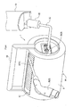
- a charging-cable storage device 1 is a storage device that stores a charging cable 3 used for an electrically-driven vehicle having an electrically-driven motor for traveling, as shown in FIG. 1 .
- the charging cable 3 has a charging control box 3A provided thereto.
- the charging control box 3A has a control circuit incorporated therein, such as a CCID (Charge Circuit Interrupt Device) and the like, which control circuit provides a charge control. Further, the charging control box 3A is provided in an electric circuit that connects a charging power source with the electrically-driven vehicle.
- CCID Charge Circuit Interrupt Device
- the charging control box 3A is supplied, by an automotive manufacturer or the like, as a part of the charging cable 3.
- a part of the charging cable 3 positioned nearer the charging power source in relation to the charging control box 3A will be named as a terminal-side charging cable 3B.
- a part of the charging cable 3 positioned nearer the electrically-driven vehicle in relation to the charging control box 3A will be named as a rewound-side charging cable 3C.
- An end of the terminal-side charging cable 3B has a terminal connector 3D to be connected to the charging power source.
- An end of the rewound-side charging cable 3C has a vehicle-side connector 3E to be connected to the electrically-driven vehicle.
- the charging-cable storage device 1 includes a rotating drum 5 that rewinds the rewound-side charging cable 3C, a casing 9 that stores the rotating drum 5, and so on.
- the rotating drum 5 includes a cylinder 5B, a drum body 7, and so on.
- the cylinder 5B is a cylindrical member having a rewind groove 5A spirally provided in an outer periphery of the cylinder 5B.
- the drum body 7 is fit into an inner periphery of the cylinder 5B.
- both of the cylinder 5B and the drum body 7 are made of resin.
- the cylinder 5B and the drum body 7 need to be fit together so as to generate a frictional force in such a manner that the drum body 7 does not slip with respect to the cylinder 5B at contact portions between the drum body 7 and the cylinder 5B, when pulling out the rewound-side charging cable 3C or when rewinding the rewound-side charging cable 3C.
- a convex portion 7A projecting toward the inner periphery of the cylinder 5B, such that an area of the contact portions between the drum body 7 and the cylinder 5B becomes small, thereby increasing pressure on such contact portions.
- a plurality of the convex portion 7A are provided in an axial direction of the rotating drum 5 (three convex portions 7A are provided in the present embodiment).
- Each of the convex portions 7A is flange-shaped and projects throughout the entirety of the outer periphery of the drum body 7.
- a fixing portion 7B that fixes the charging control box 3A.
- the fixing portion 7B is configured by a storage space that can store the charging control box 3A extending in an axial direction. As shown in FIG. 3 , an inner wall surface of the storage space constituting the fixing portion 7B and an outer wall of the charging control box 3A are pressed against each other, whereby the charging control box 3A is fixed to an inside of the drum body 7.
- an insertion hole 7C extending in a radial direction from one end of the fixing portion 7B, i.e., the storage space, in the axial direction to the cylinder 5B.
- the rewound-side charging cable 3C extends from one end of the cylinder 5B in the axial direction via the insertion hole 7C to the rewind groove 5A.
- the charging control box 3A is fixed to the rotating drum 5. Therefore, in the present embodiment, when the rotating drum 5 is rotated, the terminal-side charging cable 3B is rotated along therewith. Thus, it is desirable that the rotating drum 5 is rotated, i.e., the rewound-side charging cable 3C is pulled out or rewound, after the terminal connector 3D is detached from the power-source-side connector 30 and attached to the connector rest 7D.
- the casing 9 includes a casing body 9A that is cylinder-shaped and that stores the rotating drum 5, a gripper 9B that is substantially U-shaped and that is attached to both ends of the casing body 9A in the axial direction, or the like.
- an opening 9C extending in the axial direction.
- the opening 9C is an insertion opening through which the rewound-side charging cable 3C is inserted and/or pulled out when the rewound-side charging cable 3C rewound by the rotating drum 5 is inserted into and/or pulled out from the casing body 9A.
- a bearing portion 9D that slidably contacts with the drum body 7, that is, a shaft portion 7E provided at each of both axial ends of the rotating drum 5, thereby rotatably holding the rotating drum 5. Therefore, the rotating drum 5 can be rotated with respect to the casing 9.
- a handle 11 that can be gripped by a user. Therefore, when the user grips the handle 11 and rotates the rotating drum 5, the rewound-side charging cable 3C can be rewound around the rotating drum 5
- the casing 9 is configured such that a first casing positioned in the one axial end and a second casing positioned in the other axial end are attachably and detachably assembled.
- the first casing and the second casing each of which constitutes the casing 9 divided into two, are assembled and fixed so as to sandwich the rotating drum 5.
- the charging-cable storage device 1 shown in FIG. 1 there has been simulated a mode of usage in which the user grips the gripper 9B.
- a mode of usage of the charging-cable storage device 1 according to the present invention should not be limited to such mode of usage.
- the charging-cable storage device 1 can be disposed in various manners, as shown in FIGs. 6A to 6C .
- the charging-cable storage device 1 it is possible to dispose the charging-cable storage device 1 in a manner in which the gripper 9B is hanged by a hook provided in a wall of a parking lot or the like (refer to FIG. 6A ), or in a manner in which there is provided, in the gripper 9B, a fixing stay 9F that fixes the charging-cable storage device 1 to a wall of a parking lot or the like, to thereby fix the charging-cable storage device 1 to the wall of the parking lot or the like (refer to FIG. 6B ).
- the fixing portion 7B that fixes the charging control box 3A, whereby the charging control box 3A can be stored in the rotating drum 5.
- the slip ring 13 includes a fixed-side brush 13A provided in the other longitudinal end of the casing 9, a rotating-side electrode ring 13B provided in the other longitudinal end of the drum body 7, or the like.
- the terminal connector 3D that is, the terminal-side charging cable 3B can be connected to the rotating-side electrode ring 13B.
- a power-source-side charging cable 15 having, on an end thereof, a connector 15A connectable to the power-source-side connector 30.
- the rotating drum 5 can be rotated while keeping the charging cable 3 to be conducted to the power-source-side connector 30, whereby it is easy to pull out and to rewind the rewound-side charging cable 3C.
- the connector rest 7D is not adopted because the power-source-side charging cable 15 is not rotated when the rotating drum 5 is rotated.
- the present embodiment is not limited to such manner.
- the connector rest 7D may be provided.
- the power-source-side charging cable 15 is inhibited from wobbling by attaching the connector 15A to the connector rest 7D, thereby increasing a portability of the charging-cable storage device 1.
- the present embodiment is not limited to such manner.
- the rotating-side electrode ring 13B can be directly connected to the terminal-side charging cable 3B or the charging control box 3A, not via the terminal connector 3D.
- a size of the charging-cable storage device 1 in an axial direction thereof can become as small as a size of the charging-cable storage device 1 in an axial direction thereof according to the first embodiment.
- the handle 11 that is hand-operated is not employed.
- a rewinding portion 17 that automatically rewinds the rewound-side charging cable 3C in the one end of the casing 9 in the axial direction.
- the rewinding portion 17 includes a spirally shaped spring 17A.
- the spring 17A is configured such that an amount of an elastic deformation thereof is increased continuously as the rotating drum 5 is rotated in a direction in which the rewound-side charging cable 3C is pulled out.
- the spring 17A makes an elastic force act on the rotating drum 5, by which elastic force the rotating drum 5 is rotated in a direction of rewinding.
- the rewound-side charging cable 3C can be automatically rewound by using the elastic force of the spring 17A, whereby a usability of the charging-cable storage device 1 can be improved.
- a ratchet mechanism (not shown) that permits the rotating drum 5 to be rotated in the direction in which the rewound-side charging cable 3C is pulled out, and that restricts the rotating drum 5 to be rotated in the direction of rewinding.
- the user When rewinding the rewound-side charging cable 3C, the user removes a state in which the rotating drum 5 is restricted by the ratchet mechanism to be rotated. Thus, the elastic force gathered in the spring 17A is released, whereby the rewound-side charging cable 3C is rewound.
- an electric motor 17B as a substitute of the spring 17A constitutes the rewinding portion 17, as shown in FIG. 9 .
- an electric power is supplied from the power-source-side connector 30 via the power-source-side charging cable 15.
- a switch (not shown) that gives instructions to activate the electric motor 17B, that is, the rewinding portion 17.
- the switch By operating the switch by the user, the rewound-side charging cable 3C can be automatically rewound and pulled out.
- the slip ring 13 is provided.
- the present invention should not be limited to such embodiment.
- the slip ring 13 can be eliminated.
- the rewinding portion 17 should not be limited to be electrically-operated by applying the electric motor 17B, or to be mechanically-operated by applying the spring 17A, such as a spiral spring and the like, and so on.
- the rewinding portion 17 can be provided in any one of one end of an inside of the rotating drum 5 in the axial direction, one end of an outside of the rotating drum 5 in the axial direction, or both ends of the rotating drum 5 in the axial direction.
- the cylinder 5B and the drum body 7 are formed separately from each other, and the drum body 7 is fitted into the cylinder 5B, thereby constituting the rotating drum 5.
- the present invention should not be limited to such embodiment.
- the cylinder 5B and the drum body 7 can be integrally molded, or the cylinder 5B and the drum body 7 can be fixed by a screw.
- the charging control box 3A is inserted into and fixed in the storage space provided in the drum body 7.
- the present embodiment should not be limited to such embodiment.
- the drum body 7 can be configured in two parts, such that the charging control box 3A is sandwiched by the two parts.
Abstract
The present invention is a charging-cable storage device that stores a charging cable and a charging control box each used for an electrically-driven vehicle having an electrically-driven motor for traveling. The charging-cable storage device includes a rotating drum that is rotatable and that rewinds the charging cable, and a fixing portion that is provided in the rotating drum and that fixes the charging control box.
Description
- This international application claims the benefit of Japanese Patent Application No.
2012-20093 filed February 1, 2012 2012-20093 - The present invention relates to a charging-cable storage device applied to an electrically-driven vehicle.
- The electrically-driven vehicle is a vehicle having an electrically-driven motor for traveling. More specifically, the electrically-driven vehicle includes, for example, an electric vehicle having only an electrically-driven motor as a driving source, a plug-in hybrid vehicle having an electrically-driven motor and an internal combustion engine, and the like.
- For example, in an invention described in
Patent Document 1, a rotating drum is wound around by a charging cable having at one end thereof a vehicle-side connector (socket) to be connected to an electrically-driven vehicle. In a storage box in which the rotating drum is rotatably stored, there is stored a charging cable having at one end thereof a power-source-side connector (socket) to be connected to a charging power source. - When charging the electrically-driven vehicle, it is necessary to pull out the charging cable winding around the rotating drum from the storage box (the storage device) and attach the vehicle-side connector to the electrically-driven vehicle, and to attach the power-source-side connector to the charging device, in a state in which the entirety of a charging-cable storage device is locked and fixed to a charging device provided at a charging power source side.
- Patent Document 1: Japanese Unexamined Patent Application Publication No.
2010-115037 - When charging the electrically-driven vehicle, a charge control box is required that has a control circuit incorporated therein, such as a CCID (Charge Circuit Interrupt Device) and the like, which control circuit provides a charge control. The charge control box needs to be disposed at a position as close as possible to the power-source-side connector in a charging path from the power-source-side connector to the electrically-driven vehicle, due to a specification limitation of the charge control box.
- In regard to the above, the aforementioned specification limitation is not taken into consideration for a charging-cable storage device described in
Patent Document 1. Therefore, such charging-cable storage devices are inadequate for use as a storage device storing a charging cable for an electrically-driven vehicle. - One aspect of the present invention is to provide a charging-cable storage device suitable for storing a charging cable for an electrically-driven vehicle.
- A charging-cable storage device of the present invention stores a charging cable and a charging control box each used for an electrically-driven vehicle having an electrically-driven motor for traveling. The charging-cable storage device includes a rotating drum that is rotatable and that rewinds the charging cable, and a fixing portion that is provided in the rotating drum and that fixes the charging control box.
- Thus, in the present invention, there is provided, in the rotating drum, the fixing portion that fixes the charging control box, whereby the charging control box can be stored in the rotating drum.
- Therefore, as compared with the case in which a charging control box is disposed on an outside of the rotating drum, a dead space inside the rotating drum is effectively utilized, while the charging control box is protected, whereby the charging-cable storage device can be downsized.
- While the charging control box is protected, the charging control box can be disposed at a position close to the power-source-side connector and the charging-cable storage device can be downsized. Therefore, it is possible to achieve a charging-cable storage device suitable for storing a charging cable used for the electrically-driven vehicle.
- In the present invention, the charging control box is not a requirement for a configuration of the present invention, but the fixing portion that fixes the charging control box is.
- Therefore, it is apparent that the charging control box can be, for example, an accessory of a vehicle, purchased separately, or the like. Further, the charging control box can be supplied as an accessory of the charging-cable storage device according to the present invention.
-
-
FIG. 1 is a perspective view of an external appearance of a charging-cable storage device according to a first embodiment of the present invention. -
FIG. 2 is an axial sectional view of the charging-cable storage device in an axial direction thereof according to the first embodiment of the present invention. -
FIG. 3 is an axial sectional view of the charging-cable storage device in a direction perpendicular to the axial direction thereof according to the first embodiment of the present invention. -
FIG. 4 is a view showing a mode of usage of the charging-cable storage device according to the first embodiment of the present invention. -
FIG. 5 is a perspective view of an external appearance of the charging-cable storage device according to the first embodiment of the present invention. -
FIGS. 6A to 6C are views each showing, as an example, a mode of installation of the charging-cable storage device according to the present invention. -
FIG. 7 is an axial sectional perspective view of a charging-cable storage device in the axial direction thereof according to a second embodiment of the present invention. -
FIG. 8 is an axial sectional perspective view of a charging-cable storage device in the axial direction thereof according to a third embodiment of the present invention. -
FIG. 9 is an axial sectional perspective view of a charging-cable storage device in the axial direction thereof according to a fourth embodiment of the present invention. - 1... charging-cable storage device, 3...charging cable, 3A...charging control box, 3B...terminal-side charging cable, 3C...rewound-side charging cable, 3D...terminal connector, 3E...vehicle-side connector, 5...rotating drum, 5A...rewind groove, 5B...cylinder, 7...drum body, 7A...convex portion, 7B...fixing portion, 7C...insertion hole, 7D...connector rest, 7E... shaft portion, 9... casing, 9A...casing body, 9C... opening, 9D...bearing portion, 9B...gripper, 9F...fixing stay, 9G...hole, 11...handle, 13...slip ring, 13A...fixed-side brush, 13B...rotating-side electrode ring, 15A...connector, 15...power-source-side charging cable, 17...rewinding portion, 17A...spring, 17B...electric motor, 30...power-source-side connector
- "Embodiments of the invention" to be described hereinafter each shows one example of the embodiments. That is, matters specifying the invention or the like described in the scope of the claims are not limited to specific procedures, configurations, or the like to be described in the embodiments set forth below.
- Each of the present embodiments describes a charging-cable storage device for an electrically-driven vehicle, such as a plug-in hybrid vehicle, to which the present invention is applied. Hereinafter, the embodiments of the present invention will be described with reference to the drawings.
- A charging-
cable storage device 1 is a storage device that stores acharging cable 3 used for an electrically-driven vehicle having an electrically-driven motor for traveling, as shown inFIG. 1 . - The
charging cable 3 has acharging control box 3A provided thereto. Thecharging control box 3A has a control circuit incorporated therein, such as a CCID (Charge Circuit Interrupt Device) and the like, which control circuit provides a charge control. Further, thecharging control box 3A is provided in an electric circuit that connects a charging power source with the electrically-driven vehicle. - For this reason, in many cases, the
charging control box 3A is supplied, by an automotive manufacturer or the like, as a part of thecharging cable 3. Hereinafter, a part of thecharging cable 3 positioned nearer the charging power source in relation to thecharging control box 3A will be named as a terminal-side charging cable 3B. A part of thecharging cable 3 positioned nearer the electrically-driven vehicle in relation to thecharging control box 3A will be named as a rewound-side charging cable 3C. - An end of the terminal-
side charging cable 3B has aterminal connector 3D to be connected to the charging power source. An end of the rewound-side charging cable 3C has a vehicle-side connector 3E to be connected to the electrically-driven vehicle. - In other words, the
charging cable 3 according to the present embodiment includes thecharging control box 3A, the terminal-side charging cable 3B, the rewound-side charging cable 3C, theterminal connector 3D, the vehicle-side connector 3E, and the like. - As shown in
FIG. 2 , the charging-cable storage device 1 includes a rotatingdrum 5 that rewinds the rewound-side charging cable 3C, acasing 9 that stores the rotatingdrum 5, and so on. The rotatingdrum 5 includes acylinder 5B, adrum body 7, and so on. - The
cylinder 5B is a cylindrical member having arewind groove 5A spirally provided in an outer periphery of thecylinder 5B. Thedrum body 7 is fit into an inner periphery of thecylinder 5B. In the present embodiment, both of thecylinder 5B and thedrum body 7 are made of resin. - The
cylinder 5B and thedrum body 7 need to be fit together so as to generate a frictional force in such a manner that thedrum body 7 does not slip with respect to thecylinder 5B at contact portions between thedrum body 7 and thecylinder 5B, when pulling out the rewound-side charging cable 3C or when rewinding the rewound-side charging cable 3C. - In the present embodiment, in an outer periphery of the
drum body 7, there is provided aconvex portion 7A projecting toward the inner periphery of thecylinder 5B, such that an area of the contact portions between thedrum body 7 and thecylinder 5B becomes small, thereby increasing pressure on such contact portions. - A plurality of the
convex portion 7A are provided in an axial direction of the rotating drum 5 (threeconvex portions 7A are provided in the present embodiment). Each of theconvex portions 7A is flange-shaped and projects throughout the entirety of the outer periphery of thedrum body 7. - In the
drum body 7, there is provided a fixingportion 7B that fixes the chargingcontrol box 3A. The fixingportion 7B is configured by a storage space that can store the chargingcontrol box 3A extending in an axial direction. As shown inFIG. 3 , an inner wall surface of the storage space constituting the fixingportion 7B and an outer wall of the chargingcontrol box 3A are pressed against each other, whereby the chargingcontrol box 3A is fixed to an inside of thedrum body 7. - As shown in
FIG. 2 , in one end of thedrum body 7 in the axial direction, there is provided aninsertion hole 7C extending in a radial direction from one end of the fixingportion 7B, i.e., the storage space, in the axial direction to thecylinder 5B. The rewound-side charging cable 3C extends from one end of thecylinder 5B in the axial direction via theinsertion hole 7C to therewind groove 5A. - In the other end of the
drum body 7 in the axial direction, there is provided aconnector rest 7D to/from which theterminal connector 3D can be attached and detached. By attaching theterminal connector 3D to theconnector rest 7D, it is possible to inhibit theterminal connector 3D and the terminal-side charging cable 3B from wobbling during non-charging time. As shown inFIG. 4 , when charging, theterminal connector 3D is detached from theconnector rest 7D. Then, theterminal connector 3D is attached to a power-source-side connector 30. - The charging
control box 3A is fixed to therotating drum 5. Therefore, in the present embodiment, when therotating drum 5 is rotated, the terminal-side charging cable 3B is rotated along therewith. Thus, it is desirable that therotating drum 5 is rotated, i.e., the rewound-side charging cable 3C is pulled out or rewound, after theterminal connector 3D is detached from the power-source-side connector 30 and attached to theconnector rest 7D. - As shown in
FIG. 1 , thecasing 9 includes acasing body 9A that is cylinder-shaped and that stores therotating drum 5, agripper 9B that is substantially U-shaped and that is attached to both ends of thecasing body 9A in the axial direction, or the like. - In an outer periphery of the
casing body 9A, there is provided anopening 9C extending in the axial direction. The opening 9C is an insertion opening through which the rewound-side charging cable 3C is inserted and/or pulled out when the rewound-side charging cable 3C rewound by therotating drum 5 is inserted into and/or pulled out from thecasing body 9A. - As shown in
FIG. 2 , in thecasing 9, there is provided abearing portion 9D that slidably contacts with thedrum body 7, that is, ashaft portion 7E provided at each of both axial ends of therotating drum 5, thereby rotatably holding therotating drum 5. Therefore, therotating drum 5 can be rotated with respect to thecasing 9. - As shown in
FIG. 5 , in the one axial end of thedrum body 7, there is provided ahandle 11 that can be gripped by a user. Therefore, when the user grips thehandle 11 and rotates therotating drum 5, the rewound-side charging cable 3C can be rewound around therotating drum 5 - The
casing 9 according to the present embodiment is configured such that a first casing positioned in the one axial end and a second casing positioned in the other axial end are attachably and detachably assembled. When therotating drum 5 is stored into thecasing 9, the first casing and the second casing, each of which constitutes thecasing 9 divided into two, are assembled and fixed so as to sandwich therotating drum 5. - In regard to the charging-
cable storage device 1 shown inFIG. 1 , there has been simulated a mode of usage in which the user grips thegripper 9B. However, a mode of usage of the charging-cable storage device 1 according to the present invention should not be limited to such mode of usage. For example, the charging-cable storage device 1 can be disposed in various manners, as shown inFIGs. 6A to 6C . - It is possible to dispose the charging-
cable storage device 1 in a manner in which thegripper 9B is hanged by a hook provided in a wall of a parking lot or the like (refer toFIG. 6A ), or in a manner in which there is provided, in thegripper 9B, a fixingstay 9F that fixes the charging-cable storage device 1 to a wall of a parking lot or the like, to thereby fix the charging-cable storage device 1 to the wall of the parking lot or the like (refer toFIG. 6B ). Further, it is possible to dispose the charging-cable storage device 1 in a manner in which ahole 9G is provided in thegripper 9B such that fastener such as a bolt can be inserted through thehole 9G, and in which the charging-cable storage device 1 is vertically installed such that the axial direction thereof corresponds to a vertical direction thereof (refer toFIG. 6C ), or the like. - In the present embodiment, there is provided, in the
rotating drum 5, the fixingportion 7B that fixes the chargingcontrol box 3A, whereby the chargingcontrol box 3A can be stored in therotating drum 5. - Therefore, as compared with the case in which the charging
control box 3A is disposed on an outside of therotating drum 5, a dead space inside therotating drum 5 is effectively utilized, while the chargingcontrol box 3A is protected, whereby the charging-cable storage device 1 can be downsized. - While the charging
control box 3A is protected, the chargingcontrol box 3A can be disposed at a position close to the power-source-side connector 30 and the charging-cable storage device 1 can be downsized. Therefore, it is possible to achieve the charging-cable storage device 1 being suitable for storing the chargingcable 3 used for the electrically-driven vehicle. - In the present embodiment, as shown in
FIG. 7 , there is slidably provided an electric contact that can be rotated, such as aslip ring 13 and the like. Therefore, the chargingcable 3 can be conducted to the power-source-side connector 30 even when therotating drum 5 is rotated. - The
slip ring 13 according to the present embodiment includes a fixed-side brush 13A provided in the other longitudinal end of thecasing 9, a rotating-side electrode ring 13B provided in the other longitudinal end of thedrum body 7, or the like. - The
terminal connector 3D, that is, the terminal-side charging cable 3B can be connected to the rotating-side electrode ring 13B. To the fixed-side brush 13A, there is connected a power-source-side charging cable 15 having, on an end thereof, aconnector 15A connectable to the power-source-side connector 30. - Therefore, in the present embodiment, the
rotating drum 5 can be rotated while keeping the chargingcable 3 to be conducted to the power-source-side connector 30, whereby it is easy to pull out and to rewind the rewound-side charging cable 3C. - In the present embodiment, in
FIG. 7 , theconnector rest 7D is not adopted because the power-source-side charging cable 15 is not rotated when therotating drum 5 is rotated. However, the present embodiment is not limited to such manner. Theconnector rest 7D may be provided. - The power-source-
side charging cable 15 is inhibited from wobbling by attaching theconnector 15A to theconnector rest 7D, thereby increasing a portability of the charging-cable storage device 1. - Further, it is simulated that, to the charging-
cable storage device 1 shown inFIG. 7 , there is applied the chargingcable 3 supplied by an automotive manufacturer or the like, whereby theterminal connector 3D can be attached to the rotating-side electrode ring 13B. - However, the present embodiment is not limited to such manner. For example, the rotating-
side electrode ring 13B can be directly connected to the terminal-side charging cable 3B or the chargingcontrol box 3A, not via theterminal connector 3D. In such a manner, a size of the charging-cable storage device 1 in an axial direction thereof can become as small as a size of the charging-cable storage device 1 in an axial direction thereof according to the first embodiment. - In the present embodiment, the
handle 11 that is hand-operated is not employed. As shown inFIG. 8 , there is provided a rewindingportion 17 that automatically rewinds the rewound-side charging cable 3C in the one end of thecasing 9 in the axial direction. - The rewinding
portion 17 according to the present embodiment includes a spirally shapedspring 17A. Thespring 17A is configured such that an amount of an elastic deformation thereof is increased continuously as therotating drum 5 is rotated in a direction in which the rewound-side charging cable 3C is pulled out. - Therefore, when the rewound-
side charging cable 3C is pulled out, thespring 17A makes an elastic force act on therotating drum 5, by which elastic force therotating drum 5 is rotated in a direction of rewinding. Thus, the rewound-side charging cable 3C can be automatically rewound by using the elastic force of thespring 17A, whereby a usability of the charging-cable storage device 1 can be improved. - In the rewinding
portion 17, there is provided a ratchet mechanism (not shown) that permits therotating drum 5 to be rotated in the direction in which the rewound-side charging cable 3C is pulled out, and that restricts therotating drum 5 to be rotated in the direction of rewinding. - When rewinding the rewound-
side charging cable 3C, the user removes a state in which therotating drum 5 is restricted by the ratchet mechanism to be rotated. Thus, the elastic force gathered in thespring 17A is released, whereby the rewound-side charging cable 3C is rewound. - In the present embodiment, an
electric motor 17B as a substitute of thespring 17A constitutes the rewindingportion 17, as shown inFIG. 9 . To theelectric motor 17B, an electric power is supplied from the power-source-side connector 30 via the power-source-side charging cable 15. - In the
gripper 9B, there is provided a switch (not shown) that gives instructions to activate theelectric motor 17B, that is, the rewindingportion 17. By operating the switch by the user, the rewound-side charging cable 3C can be automatically rewound and pulled out. - In Embodiment 4, the
slip ring 13 is provided. However, the present invention should not be limited to such embodiment. As inEmbodiment 1, theslip ring 13 can be eliminated. - The rewinding
portion 17 should not be limited to be electrically-operated by applying theelectric motor 17B, or to be mechanically-operated by applying thespring 17A, such as a spiral spring and the like, and so on. In this case, the rewindingportion 17 can be provided in any one of one end of an inside of therotating drum 5 in the axial direction, one end of an outside of therotating drum 5 in the axial direction, or both ends of therotating drum 5 in the axial direction. - In the above-described embodiments, the
cylinder 5B and thedrum body 7 are formed separately from each other, and thedrum body 7 is fitted into thecylinder 5B, thereby constituting therotating drum 5. However, the present invention should not be limited to such embodiment. Thecylinder 5B and thedrum body 7 can be integrally molded, or thecylinder 5B and thedrum body 7 can be fixed by a screw. - Further, in the above-described embodiments, the charging
control box 3A is inserted into and fixed in the storage space provided in thedrum body 7. However, the present embodiment should not be limited to such embodiment. For example, thedrum body 7 can be configured in two parts, such that the chargingcontrol box 3A is sandwiched by the two parts. - The present invention only has to correspond to the spirit of the inventions described in claims, and should not be limited to the aforementioned embodiments.
Claims (5)
- A charging-cable storage device that stores a charging cable and a charging control box each used for an electrically-driven vehicle having an electrically-driven motor for traveling, the device comprising:a rotating drum that is rotatable and that rewinds the charging cable; anda fixing portion that is provided in the rotating drum and that fixes the charging control box.
- The charging-cable storage device according to claim 1,
wherein, in an end of the rotating drum in an axial direction, a rewinding portion is provided that makes a force act on the rotating drum, by which force the charging cable is rewound. - The charging-cable storage device according to claim 2,
wherein the rewinding portion comprises a spring that can be elastically deformed and that generates the force by which the rotating drum is rotated, and
wherein the rewinding portion is configured such that an amount of an elastic deformation of the spring is increased continuously as the rotating drum is rotated in a direction in which the charging cable is pulled out. - The charging-cable storage device according to any one of claims 1 to 3,
wherein a rewind groove is spirally provided in an outer periphery of the rotating drum. - The charging-cable storage device according to any one of claims 1 to 4,
wherein the fixing portion is a storage space provided in the rotating drum, in which storage space the charging control box is stored.
Applications Claiming Priority (2)
| Application Number | Priority Date | Filing Date | Title |
|---|---|---|---|
| JP2012020093A JP2013162550A (en) | 2012-02-01 | 2012-02-01 | Housing device for charging cable |
| PCT/JP2013/052373 WO2013115375A1 (en) | 2012-02-01 | 2013-02-01 | Charging-cable storage device |
Publications (1)
| Publication Number | Publication Date |
|---|---|
| EP2811610A1 true EP2811610A1 (en) | 2014-12-10 |
Family
ID=48905402
Family Applications (1)
| Application Number | Title | Priority Date | Filing Date |
|---|---|---|---|
| EP13743419.7A Withdrawn EP2811610A1 (en) | 2012-02-01 | 2013-02-01 | Charging-cable storage device |
Country Status (5)
| Country | Link |
|---|---|
| US (1) | US20150008878A1 (en) |
| EP (1) | EP2811610A1 (en) |
| JP (1) | JP2013162550A (en) |
| CN (1) | CN104094495A (en) |
| WO (1) | WO2013115375A1 (en) |
Cited By (1)
| Publication number | Priority date | Publication date | Assignee | Title |
|---|---|---|---|---|
| WO2023166308A1 (en) * | 2022-03-04 | 2023-09-07 | Albright Product Design Limited | Cable reel assembly |
Families Citing this family (27)
| Publication number | Priority date | Publication date | Assignee | Title |
|---|---|---|---|---|
| WO2014209261A1 (en) * | 2013-06-24 | 2014-12-31 | Schneider Electric USA, Inc. | Electric vehicle charging station locking cable reel |
| JP2017034311A (en) * | 2015-07-28 | 2017-02-09 | 株式会社リコー | Information processing device, information processing system, and program |
| CN105762886A (en) * | 2016-04-19 | 2016-07-13 | 北京新能源汽车股份有限公司 | Charging gun device for electric car |
| FR3051986B1 (en) | 2016-05-26 | 2018-05-18 | Renault S.A.S | PORTABLE DEVICE FOR THE DEVIDING OF AN ELECTRIC CABLE, IN PARTICULAR A LOAD CABLE FOR AN ELECTRIC OR HYBRID VEHICLE |
| FR3052925B1 (en) | 2016-06-15 | 2018-08-17 | Renault S.A.S | PORTABLE DEVICE FOR THE DEVIDING OF AN ELECTRIC CABLE, IN PARTICULAR A LOAD CABLE FOR AN ELECTRIC OR HYBRID VEHICLE |
| CN105831966A (en) * | 2016-06-18 | 2016-08-10 | 安徽科技学院 | Telescopic cartoon sucker brush |
| JP6841636B2 (en) * | 2016-11-18 | 2021-03-10 | トヨタホーム株式会社 | Vehicle protection structure when connecting vehicle protection member and charging cable |
| US10814733B2 (en) * | 2016-12-20 | 2020-10-27 | Hubbell Incorporated | Electrical vehicle charger and integrated cord management system |
| DE102017208599B4 (en) * | 2017-05-22 | 2022-02-03 | Audi Ag | Motor vehicle with a connection device |
| CN107833675B (en) * | 2017-11-22 | 2024-01-30 | 上海传输线研究所(中国电子科技集团公司第二十三研究所) | High-reliability spiral cable set for space station |
| CN108528228B (en) * | 2018-02-06 | 2019-11-22 | 杭州电子科技大学 | A kind of electric car ejection type charging unit |
| CN108357981A (en) * | 2018-04-02 | 2018-08-03 | 聊城大学 | Coordinate the charging wire draw off gear and its method of charging pile |
| CN108439089A (en) * | 2018-05-30 | 2018-08-24 | 成都特来电新能源有限公司 | A kind of charging pile convenient for storage cable |
| CN108511996B (en) * | 2018-05-30 | 2024-04-05 | 成都特来电新能源有限公司 | A take-up for charging stake |
| DE102018210227A1 (en) * | 2018-06-22 | 2019-12-24 | Schill GmbH & Co. KG | cable drum |
| DE102018122663A1 (en) * | 2018-09-17 | 2020-03-19 | Stemmann-Technik Gmbh | Line feed arrangement |
| JP7233683B2 (en) * | 2018-11-27 | 2023-03-07 | 日本ケーブル株式会社 | Pallet for multi-storey parking system |
| CN109399346A (en) * | 2018-11-28 | 2019-03-01 | 大连海洋明天科技有限公司 | A kind of novel sea engineering high-efficiency cable recyclable device and method |
| US11121562B2 (en) * | 2019-12-23 | 2021-09-14 | Jeff W H Li | System for automated charging management |
| CN112172557B (en) * | 2020-08-13 | 2021-10-26 | 大连海洋大学 | New forms of energy are charged with rolling joint that charges |
| CN112606723B (en) * | 2021-01-08 | 2022-09-13 | 四川沃轮电气制造有限公司 | New energy automobile is with filling electric pile |
| CN112919237B (en) * | 2021-02-02 | 2022-08-19 | 士商(湖州)精密技术有限公司 | Electric winder and control method thereof |
| US11273724B1 (en) * | 2021-06-29 | 2022-03-15 | Beta Air, Llc | Recharging station for electric aircrafts and a method of its use |
| US11623535B1 (en) * | 2022-05-04 | 2023-04-11 | Beta Air, Llc | Methods and systems for charging an electric aircraft including a horizontal cable arrangement |
| US11618328B1 (en) * | 2022-05-04 | 2023-04-04 | Beta Air, Llc | Methods and systems for charging an electric aircraft including a vertical cable arrangement |
| CN114803732A (en) * | 2022-05-13 | 2022-07-29 | 丁超 | Medical catheter storage and supply device |
| US11685277B1 (en) * | 2022-08-18 | 2023-06-27 | Beta Air, Llc | Electric vehicle charger for an electric vehicle and a method of use |
Family Cites Families (9)
| Publication number | Priority date | Publication date | Assignee | Title |
|---|---|---|---|---|
| US3547371A (en) * | 1968-10-30 | 1970-12-15 | Horst A Gruseck | Water skiing tow rope retriever |
| SE400262B (en) * | 1975-10-01 | 1978-03-20 | Nitro Nobel Ab | HOSE FEED WIND |
| SE8701749D0 (en) * | 1987-04-28 | 1987-04-28 | Electrolux Ab | DEVICE FOR WIRING AN ELECTRIC CABLE |
| JPH0194362U (en) * | 1987-12-11 | 1989-06-21 | ||
| JP3143001U (en) * | 2008-04-23 | 2008-07-03 | 大和電器株式会社 | Device for charging digital equipment |
| JP5062330B2 (en) * | 2008-10-09 | 2012-10-31 | トヨタ自動車株式会社 | Connection device |
| JP2010110053A (en) * | 2008-10-28 | 2010-05-13 | Panasonic Electric Works Co Ltd | Charging system for electric vehicle |
| JP5408765B2 (en) | 2008-11-07 | 2014-02-05 | 日東工業株式会社 | Car charging connection cable storage box and charging device |
| JP5481433B2 (en) * | 2011-06-17 | 2014-04-23 | パナソニック株式会社 | Electric vehicle power line storage device and functional gatepost that can store this storage |
-
2012
- 2012-02-01 JP JP2012020093A patent/JP2013162550A/en active Pending
-
2013
- 2013-02-01 WO PCT/JP2013/052373 patent/WO2013115375A1/en active Application Filing
- 2013-02-01 CN CN201380007163.6A patent/CN104094495A/en active Pending
- 2013-02-01 EP EP13743419.7A patent/EP2811610A1/en not_active Withdrawn
- 2013-02-01 US US14/375,369 patent/US20150008878A1/en not_active Abandoned
Cited By (1)
| Publication number | Priority date | Publication date | Assignee | Title |
|---|---|---|---|---|
| WO2023166308A1 (en) * | 2022-03-04 | 2023-09-07 | Albright Product Design Limited | Cable reel assembly |
Also Published As
| Publication number | Publication date |
|---|---|
| CN104094495A (en) | 2014-10-08 |
| WO2013115375A1 (en) | 2013-08-08 |
| JP2013162550A (en) | 2013-08-19 |
| US20150008878A1 (en) | 2015-01-08 |
Similar Documents
| Publication | Publication Date | Title |
|---|---|---|
| EP2811610A1 (en) | Charging-cable storage device | |
| WO2013125573A1 (en) | Cable housing device | |
| EP2814128A1 (en) | Apparatus for housing charging cable | |
| JP5877108B2 (en) | Cable housing device | |
| JP5531895B2 (en) | Charging cable connection structure and vehicle charging port | |
| KR20180128557A (en) | Charging cable winding apparatus for the electric vehicle charger | |
| WO2012172626A1 (en) | Cable winding device, vehicle and power source device | |
| JP2010172126A (en) | Charging cable for vehicle | |
| JP2012157176A (en) | Protector for wire harness | |
| JP2014110656A (en) | Charger | |
| JP5609698B2 (en) | Charging device and charging equipment | |
| JP2017073839A (en) | Portable power feeding apparatus | |
| KR101028733B1 (en) | Wire binding device | |
| KR20100005689U (en) | Portable charging device for cellular phone | |
| WO2013179508A1 (en) | Storage apparatus for charging cable | |
| JP2013067197A (en) | Electric door mirror | |
| WO2012056517A1 (en) | Storage structure of charging cable | |
| JP3190718U (en) | Charger | |
| JP6176026B2 (en) | Power supply connector for electric vehicles | |
| JP2012221894A (en) | Power feed connector | |
| JP6164081B2 (en) | Power supply connector for electric vehicles | |
| KR200360215Y1 (en) | Winding device of electric wire / hose using coil spring | |
| JP2016069176A (en) | Storage device for charging cable | |
| KR100583186B1 (en) | Winding device of electric wire / hose using coil spring | |
| WO2013111869A1 (en) | Charging cable housing device |
Legal Events
| Date | Code | Title | Description |
|---|---|---|---|
| PUAI | Public reference made under article 153(3) epc to a published international application that has entered the european phase |
Free format text: ORIGINAL CODE: 0009012 |
|
| 17P | Request for examination filed |
Effective date: 20140813 |
|
| AK | Designated contracting states |
Kind code of ref document: A1 Designated state(s): AL AT BE BG CH CY CZ DE DK EE ES FI FR GB GR HR HU IE IS IT LI LT LU LV MC MK MT NL NO PL PT RO RS SE SI SK SM TR |
|
| AX | Request for extension of the european patent |
Extension state: BA ME |
|
| STAA | Information on the status of an ep patent application or granted ep patent |
Free format text: STATUS: THE APPLICATION HAS BEEN WITHDRAWN |
|
| 18W | Application withdrawn |
Effective date: 20150126 |