EP2811336B1 - Illuminating apparatus and liquid crystal display having the same - Google Patents
Illuminating apparatus and liquid crystal display having the same Download PDFInfo
- Publication number
- EP2811336B1 EP2811336B1 EP14153933.8A EP14153933A EP2811336B1 EP 2811336 B1 EP2811336 B1 EP 2811336B1 EP 14153933 A EP14153933 A EP 14153933A EP 2811336 B1 EP2811336 B1 EP 2811336B1
- Authority
- EP
- European Patent Office
- Prior art keywords
- support member
- light source
- light emitting
- corner
- illuminating apparatus
- Prior art date
- Legal status (The legal status is an assumption and is not a legal conclusion. Google has not performed a legal analysis and makes no representation as to the accuracy of the status listed.)
- Active
Links
- 239000004973 liquid crystal related substance Substances 0.000 title claims description 37
- 238000005452 bending Methods 0.000 claims description 11
- 238000000034 method Methods 0.000 description 4
- 239000007769 metal material Substances 0.000 description 3
- 238000010276 construction Methods 0.000 description 2
- 230000003287 optical effect Effects 0.000 description 2
- 230000001737 promoting effect Effects 0.000 description 2
- XAGFODPZIPBFFR-UHFFFAOYSA-N aluminium Chemical compound [Al] XAGFODPZIPBFFR-UHFFFAOYSA-N 0.000 description 1
- 229910052782 aluminium Inorganic materials 0.000 description 1
- 230000000712 assembly Effects 0.000 description 1
- 238000000429 assembly Methods 0.000 description 1
- 230000015556 catabolic process Effects 0.000 description 1
- 230000003247 decreasing effect Effects 0.000 description 1
- 238000006731 degradation reaction Methods 0.000 description 1
- 230000001419 dependent effect Effects 0.000 description 1
- 238000009792 diffusion process Methods 0.000 description 1
- 239000000463 material Substances 0.000 description 1
- 239000000203 mixture Substances 0.000 description 1
- 238000012986 modification Methods 0.000 description 1
- 230000004048 modification Effects 0.000 description 1
- 238000004064 recycling Methods 0.000 description 1
- 239000004065 semiconductor Substances 0.000 description 1
- 229910000679 solder Inorganic materials 0.000 description 1
Images


Classifications
-
- F—MECHANICAL ENGINEERING; LIGHTING; HEATING; WEAPONS; BLASTING
- F21—LIGHTING
- F21K—NON-ELECTRIC LIGHT SOURCES USING LUMINESCENCE; LIGHT SOURCES USING ELECTROCHEMILUMINESCENCE; LIGHT SOURCES USING CHARGES OF COMBUSTIBLE MATERIAL; LIGHT SOURCES USING SEMICONDUCTOR DEVICES AS LIGHT-GENERATING ELEMENTS; LIGHT SOURCES NOT OTHERWISE PROVIDED FOR
- F21K9/00—Light sources using semiconductor devices as light-generating elements, e.g. using light-emitting diodes [LED] or lasers
- F21K9/20—Light sources comprising attachment means
- F21K9/27—Retrofit light sources for lighting devices with two fittings for each light source, e.g. for substitution of fluorescent tubes
-
- F—MECHANICAL ENGINEERING; LIGHTING; HEATING; WEAPONS; BLASTING
- F21—LIGHTING
- F21V—FUNCTIONAL FEATURES OR DETAILS OF LIGHTING DEVICES OR SYSTEMS THEREOF; STRUCTURAL COMBINATIONS OF LIGHTING DEVICES WITH OTHER ARTICLES, NOT OTHERWISE PROVIDED FOR
- F21V21/00—Supporting, suspending, or attaching arrangements for lighting devices; Hand grips
- F21V21/005—Supporting, suspending, or attaching arrangements for lighting devices; Hand grips for several lighting devices in an end-to-end arrangement, i.e. light tracks
-
- G—PHYSICS
- G02—OPTICS
- G02F—OPTICAL DEVICES OR ARRANGEMENTS FOR THE CONTROL OF LIGHT BY MODIFICATION OF THE OPTICAL PROPERTIES OF THE MEDIA OF THE ELEMENTS INVOLVED THEREIN; NON-LINEAR OPTICS; FREQUENCY-CHANGING OF LIGHT; OPTICAL LOGIC ELEMENTS; OPTICAL ANALOGUE/DIGITAL CONVERTERS
- G02F1/00—Devices or arrangements for the control of the intensity, colour, phase, polarisation or direction of light arriving from an independent light source, e.g. switching, gating or modulating; Non-linear optics
- G02F1/01—Devices or arrangements for the control of the intensity, colour, phase, polarisation or direction of light arriving from an independent light source, e.g. switching, gating or modulating; Non-linear optics for the control of the intensity, phase, polarisation or colour
- G02F1/13—Devices or arrangements for the control of the intensity, colour, phase, polarisation or direction of light arriving from an independent light source, e.g. switching, gating or modulating; Non-linear optics for the control of the intensity, phase, polarisation or colour based on liquid crystals, e.g. single liquid crystal display cells
- G02F1/133—Constructional arrangements; Operation of liquid crystal cells; Circuit arrangements
- G02F1/1333—Constructional arrangements; Manufacturing methods
- G02F1/1335—Structural association of cells with optical devices, e.g. polarisers or reflectors
- G02F1/1336—Illuminating devices
- G02F1/133602—Direct backlight
- G02F1/133603—Direct backlight with LEDs
-
- G—PHYSICS
- G02—OPTICS
- G02F—OPTICAL DEVICES OR ARRANGEMENTS FOR THE CONTROL OF LIGHT BY MODIFICATION OF THE OPTICAL PROPERTIES OF THE MEDIA OF THE ELEMENTS INVOLVED THEREIN; NON-LINEAR OPTICS; FREQUENCY-CHANGING OF LIGHT; OPTICAL LOGIC ELEMENTS; OPTICAL ANALOGUE/DIGITAL CONVERTERS
- G02F1/00—Devices or arrangements for the control of the intensity, colour, phase, polarisation or direction of light arriving from an independent light source, e.g. switching, gating or modulating; Non-linear optics
- G02F1/01—Devices or arrangements for the control of the intensity, colour, phase, polarisation or direction of light arriving from an independent light source, e.g. switching, gating or modulating; Non-linear optics for the control of the intensity, phase, polarisation or colour
- G02F1/13—Devices or arrangements for the control of the intensity, colour, phase, polarisation or direction of light arriving from an independent light source, e.g. switching, gating or modulating; Non-linear optics for the control of the intensity, phase, polarisation or colour based on liquid crystals, e.g. single liquid crystal display cells
- G02F1/133—Constructional arrangements; Operation of liquid crystal cells; Circuit arrangements
- G02F1/1333—Constructional arrangements; Manufacturing methods
- G02F1/1335—Structural association of cells with optical devices, e.g. polarisers or reflectors
- G02F1/1336—Illuminating devices
- G02F1/133602—Direct backlight
- G02F1/133608—Direct backlight including particular frames or supporting means
-
- G—PHYSICS
- G02—OPTICS
- G02F—OPTICAL DEVICES OR ARRANGEMENTS FOR THE CONTROL OF LIGHT BY MODIFICATION OF THE OPTICAL PROPERTIES OF THE MEDIA OF THE ELEMENTS INVOLVED THEREIN; NON-LINEAR OPTICS; FREQUENCY-CHANGING OF LIGHT; OPTICAL LOGIC ELEMENTS; OPTICAL ANALOGUE/DIGITAL CONVERTERS
- G02F1/00—Devices or arrangements for the control of the intensity, colour, phase, polarisation or direction of light arriving from an independent light source, e.g. switching, gating or modulating; Non-linear optics
- G02F1/01—Devices or arrangements for the control of the intensity, colour, phase, polarisation or direction of light arriving from an independent light source, e.g. switching, gating or modulating; Non-linear optics for the control of the intensity, phase, polarisation or colour
- G02F1/13—Devices or arrangements for the control of the intensity, colour, phase, polarisation or direction of light arriving from an independent light source, e.g. switching, gating or modulating; Non-linear optics for the control of the intensity, phase, polarisation or colour based on liquid crystals, e.g. single liquid crystal display cells
- G02F1/133—Constructional arrangements; Operation of liquid crystal cells; Circuit arrangements
- G02F1/1333—Constructional arrangements; Manufacturing methods
- G02F1/1335—Structural association of cells with optical devices, e.g. polarisers or reflectors
- G02F1/1336—Illuminating devices
- G02F1/133602—Direct backlight
- G02F1/133611—Direct backlight including means for improving the brightness uniformity
-
- F—MECHANICAL ENGINEERING; LIGHTING; HEATING; WEAPONS; BLASTING
- F21—LIGHTING
- F21Y—INDEXING SCHEME ASSOCIATED WITH SUBCLASSES F21K, F21L, F21S and F21V, RELATING TO THE FORM OR THE KIND OF THE LIGHT SOURCES OR OF THE COLOUR OF THE LIGHT EMITTED
- F21Y2115/00—Light-generating elements of semiconductor light sources
- F21Y2115/10—Light-emitting diodes [LED]
Definitions
- Apparatuses and methods consistent with exemplary embodiments relate to an illuminating apparatus and a liquid crystal display having the same, and particularly, to an illuminating apparatus that uses light-emitting diodes as a light source and a liquid crystal display having the same.
- a light-emitting diode is a semiconductor device which generates light, and has advantages of high energy efficiency, long life, etc. Accordingly, it has been used in a variety of industries.
- one light emitting module that uses light-emitting diodes as a light source is a light emitting module having a form in which a large number of LED packages consisting of a light-emitting diode, a fluorescent member, an electrode, etc. are mounted on a long strip-shaped printed circuit board (PCB).
- a light emitting module may be applied to be mounted on an inner surface of a support member (a component is often referred to as a bottom chassis) that is arranged behind a liquid crystal panel in a liquid crystal display, thereby providing light to the liquid crystal panel by a direct lighting method.
- US 2008/0111471 A1 describes a lighting device comprising a multiplicity of light sources arranged on grid points of a regular grid.
- EP 1801637 A1 describes a liquid crystal display apparatus employing a transmissive color liquid crystal panel.
- US 2012/0099295 A1 describes a lighting device including a plurality of LEDs, an LED board, and a chassis to which the LED board is attached.
- US 2007/0279937 A1 describes a plurality of spot light sources disposed on different locations along a backlight module.
- WO 00/50807 describes light emitting panel assemblies including a light emitting panel member having a uniform or variable pattern of light extracting deformities.
- DE 19848842 A1 describes a flexible light-emitting sheet which is disposed along a curved liquid crystal display.
- Exemplary embodiments address at least the above problems and/or disadvantages and other disadvantages not described above. Also, exemplary embodiments are not required to overcome the disadvantages described above, and an exemplary embodiment may not overcome any of the problems described above.
- One or more exemplary embodiments relate to improving light uniformity of an illuminating apparatus to which a light emitting module of the form in which a large number of LED packages are mounted on a strip-shaped printed circuit board is applied, and a liquid crystal display equipped with the illuminating apparatus.
- an illuminating apparatus including: a support member including a light source support member having four corner areas; and a light emitter that is disposed on a surface of the light source support member, the light emitter including: one or more light emitting modules, wherein each of the one or more light emitting modules includes a strip-shaped printed circuit board (PCB) mounted on the light source support member and a plurality of light source packages that is mounted on the strip-shaped PCB and configured to generate light; and four corner side extending portions that configure a portion of any one of the one or more light emitting modules and are extended toward the four corner areas of the light source support member.
- PCB printed circuit board
- Each of the corner side extending portions may extend along a direction that divides a corresponding corner area into two areas.
- the light source support member of the support member may have a rectangular plate shape.
- the light emitter may include one light emitting module including the four corner side extending portions.
- the light emitting module may include: a body portion extended along a widthwise direction or a lengthwise direction of the light source support member; first and second corner side extending portions of the four corner side extending portions extended from one end of the body portion to first and second corner areas of the four corner areas of the light source support member; and third and fourth corner side extending portions of the four corner side extending portion extended from the other end of the body portion to third and fourth corner areas of the four corner areas of the light source support member.
- the light emitter may include a first light emitting module and a second light emitting module.
- the first light emitting module may include: a first body portion extended along one direction; a first corner side extending portion of the four corner side extending portions extended from an end of the first body portion to a first corner area of the four corner areas of the light source support member; and a second corner side extending portion of the four corner side extending portions extended from the other end of the first body portion to a second corner area of the four corner areas of the light source support member.
- the second light emitting module may include: a second body portion disposed parallel to the first body portion of the first light emitting module; a third corner side extending portion of the four corner side extending portions extended from an end of the second body portion to a third corner area of the four corner areas of the light source support member; and a fourth corner side extending portion of the four corner side extending portions extended from the other end of the second body portion to a fourth corner area of the four corner areas of the light source support member.
- the light emitting unit may include at least one additional light emitting module having no corner side extending portions.
- Each of the light source packages may include a light-emitting diode.
- a liquid crystal display including: a support member including a light source support member having four corner areas; a cover member that is disposed in front of the support member and configured to cover the support member; a liquid crystal panel that is disposed between the support member and the cover member and configured to display video; and a light emitter that is disposed on an inner surface of the light source support member, the light emitter including: one or more light emitting modules, wherein each of the one or more light emitting modules includes a strip-shaped printed circuit board mounted on the light source support member and a plurality of light source packages that is mounted on the printed circuit board and configured to provide light to the liquid crystal panel; and four corner side extending portions that configure a portion of any one of the one or more light emitting modules and are extended toward the four corner areas of the light source support member.
- an illuminating apparatus including: a support member including a light source support member; and a light emitter that is disposed on a surface of the light source support member and includes one or more light emitting modules, wherein each of the one or more light emitting modules includes a strip-shaped printed circuit board mounted on the light source support member and a plurality of light source packages that is mounted on the printed circuit board and configured to provide light, wherein the light source support member has non-uniform depth and is formed in a concave shape having a maximum depth in a central area thereof.
- the light source support member may have a curved plate shape.
- the light source support member may have a flat plate shape is bent into two or more portions by at least one bending line.
- the light source support member may be bent into a first support portion and a second support portion by one bending line, and at least one of the one or more light emitting modules may be mounted on each of the first support portion and the second support portion.
- the light source support member may be bent into a first support portion, a second support portion, and a third support portion by two bending lines, and at least one of the one or more light emitting modules is mounted on each of the first support portion, the second support portion, and the third support portion.
- the light source support member may have four corner areas, and the light emitter may include four corner side extending portions that configure a portion of any one of the one or more the light emitting modules and are extended toward the four corner areas.
- a liquid crystal display including: a support member including a light source support member having four corner areas; a cover member that is disposed in front of the support member and configured to cover the support member; a liquid crystal panel that is disposed between the support member and the cover member and configured to display video; and a light emitter that is disposed on an inner surface of the light source support member and includes one or more light emitting modules, wherein each of the one or more light emitting module includes a strip-shaped printed circuit board mounted on the light source support member and a plurality of light source packages that is mounted on the strip-shaped printed circuit board and configured to provide light to the liquid crystal panel, wherein the light source support member has non-uniform depth along a direction and is formed as a concave shape having a maximum depth in a central area thereof.
- a backlight including: a support member having four corner areas; and a light emitter disposed on a surface of the support member, wherein the light emitter includes at least one strip-shaped body portion and four strip-shaped corner side extending portions, wherein the at least one strip-shaped body portion extends in a longitudinal direction with respect to the support member and the four strip-shaped corner side extending portions each extend from any one of the at least one strip-shaped body portion toward a different corner area of the four corner areas such that each of the strip-shaped four corner side extending portions forms an obtuse angle with respect to a corresponding strip-shaped body portion.
- the light emitter may include a single strip-shaped body portion of the at least one strip-shaped body portion.
- First and second strip-shaped corner side extending portions of the four strip-shaped corner side extending portions may extend from a first end of the single strip-shaped body portion toward first and second corner areas of the four corner areas.
- Third and fourth strip-shaped corner side extending portions of the four strip-shaped corner side extending portions may extend from a second end of the single strip-shaped body portion toward third and fourth corner areas of the four corner areas.
- the light emitter may include a first strip-shaped body portion and a second strip-shaped body portion of the at least one strip-shaped body portion.
- a first strip-shaped corner side extending portion of the four strip-shaped corner side extending portions may extend from a first end of the first strip-shaped body portion toward a first corner area of the four corner areas.
- a second strip-shaped corner side extending portion of the four strip-shaped corner side extending portions may extend from a second end of the first strip-shaped body portion toward a second corner area of the four corner areas.
- a third strip-shaped corner side extending portion of the four strip-shaped corner side extending portions may extend from a first end of the second strip-shaped body portion toward a third corner area of the four corner areas.
- a fourth strip-shaped corner side extending portion of the four strip-shaped corner side extending portions may extend from a second end of the first strip-shaped body portion toward a fourth corner area of the four corner areas.
- the light emitter may further include at least one additional strip-shaped body portion of the at least one strip-shaped body portion disposed between the first strip-shaped body portion and the second strip-shaped body portion.
- the surface of support member may have a concave shape.
- the at least one strip-shaped body portion and the four strip-shaped corner portions may be printed circuit boards.
- Each of the at least one strip-shaped body portion and the four strip shaped corner portions may include at least one light-emitting diode disposed thereon.
- a backlight including: a support member having a surface, a first corner area, a second corner area, a third corner area, and a fourth corner area; and a plurality of strip-shaped printed circuit board (PCB) portions having disposed thereon at least one light-emitting diode, wherein the plurality of strip-shaped PCB portions is disposed on the surface of the support member, and wherein the plurality of strip-shaped PCB portions includes: a first corner side extending portion disposed in a first direction extending toward the first corner area; a second corner side extending portion disposed in a second direction extending toward the second corner area; a third corner side extending portion disposed in a third direction extending toward the third corner area; a fourth corner side extending portion disposed in a second direction extending toward the fourth corner area; at least one body portion disposed in a fifth direction.
- PCB printed circuit board
- the surface of support member may have a concave shape.
- FIG. 1 is a perspective view illustrating an illuminating apparatus according to a first exemplary embodiment
- FIG. 2 is a plan view of the illuminating apparatus of FIG. 1 .
- an illuminating apparatus 100 includes a support member 110 and a light emitting unit 120.
- the support member 110 has a rectangular box shape that has a shallow depth and an open top end.
- the support member 110 consists of a light source support member 111 of a rectangular plate shape and a side wall 112 extending from an edge of the light source support member 111.
- the light source support member 111 supports the light emitting unit 120 mounted on a surface 111a of the light source support member 111.
- the side wall 112 forms an internal space of the illuminating apparatus 100, and may be coupled to another member (not illustrated) to cover the support member 110.
- the side wall 112 is formed perpendicular to the light source support member 111.
- the side wall 112 may be formed to be inclined at an obtuse angle with respect to the light source support member 111.
- the support member 110 may be formed of a variety of materials.
- the support member 110 may be formed of a non-metallic material such as plastic or a metallic material such as aluminum.
- the metallic material may effectively radiate heat generated in the light emitting unit 120.
- the light emitting unit 120 is mounted on the surface 111a of the light source support member 111 of the support member 110, and, in the present exemplary embodiment, is configured of only one light emitting module. Accordingly, in the description of the illuminating apparatus 100 according to the first exemplary embodiment, reference number 120 will be used as a number to refer to the light emitting unit, or a number to refer to the light emitting module configuring the light emitting unit.
- the only light emitting module 120 configuring the light emitting unit 120 includes a printed circuit board (PCB) 130 of a strip shape that is mounted on the light source support member 111 of the support member 110, and a plurality of light source packages 140 that is mounted on the printed circuit board 130 and generates light.
- PCB printed circuit board
- the printed circuit board 130 supports the plurality of light source packages 140 that is mounted on a top surface thereof, and delivers power being supplied from a power source (not illustrated) to the light source packages 140.
- the light source packages 140 provide light in a direction which the surface 111a of the support member 110 faces (Z direction in FIG. 1 ).
- a structure of each of the light source packages 140 will be described hereinafter with reference to FIG. 3 that is a sectional view taken along a line I - I in FIG. 2 .
- the light source package 140 is mounted on the above-described printed circuit board 130 by using solder S, and includes a light-emitting diode 141, a fluorescent member 142, a pair of electrodes 143 and 144, and a frame 145.
- the light-emitting diode 141 is a component to generate light.
- the fluorescent member 142 converts light of a specific color generated by the light-emitting diode 141 into light of a different color (e.g. white color) that is suitable for use in the illuminating apparatus 100.
- the fluorescent member 142 may widely diffuse the light through an outer surface 142a in the form of a convex lens.
- an optical lens placed to cover the light source package 140 may perform the light diffusion function instead of the fluorescent member 142.
- the pair of electrodes 143 and 144 are components to electrically connect the light-emitting diode 141 and the printed circuit board 130.
- the frame 145 is a component to package the light-emitting diode 141, the fluorescent member 142, and the pair of electrodes 143 and 144, as described above.
- the light emitting module 120 includes a body portion 121 and four corner side extending portions 123, 124, 125, and 126 extending from the body portion 121.
- the body portion 121 is extended along a lengthwise direction (X direction in FIG. 2 ) of the support member 110.
- the body portion 121 may be arranged along a widthwise direction (Y direction in FIG. 2 ) of the support member 110, or along a direction different from the lengthwise direction and the widthwise direction.
- the four corner side extending portions 123, 124, 125, and 126 correspond to four corner areas 113, 114, 115, and 116 formed in the light source support member 111, respectively.
- a first corner side extending portion 123 corresponds to a first corner area 113 of the light source support member 111
- a second corner side extending portion 124 corresponds to a second corner area 114
- a third corner side extending portion 125 corresponds to a third corner area 115 of the light source support member 111
- a fourth corner side extending portion 126 corresponds to a fourth corner area 116 of the light source support member 111.
- the first corner side extending portion 123 is extended from one end 121a of the body portion 121 to the first corner area 113.
- the first corner side extending portion 123 is arranged along a direction ⁇ 1 that divides the first corner area 113 corresponding thereto into two areas 113a and 113b.
- the first corner side extending portion 123 is arranged close to the first corner area 113 to increase the brightness of the first corner area 113, thereby preventing a dark region from appearing in the first corner area 113.
- the second corner side extending portion 124 is extended from the one end 121a of the body portion 121 to the second corner area 114.
- the second corner side extending portion 124 is arranged along a direction ⁇ 2 that divides the second corner area 114 corresponding thereto into two areas 114a and 114b.
- the second corner side extending portion 124 is arranged close to the second corner area 114 to increase the brightness of the second corner area 114, thereby preventing a dark region from appearing in the second corner area 114.
- the third corner side extending portion 125 is extended from the other end 121b of the body portion 121 to the third corner area 115.
- the third corner side extending portion 125 is arranged along a direction ⁇ 3 that divides the third corner area 115 corresponding thereto into two areas 115a and 115b.
- the third corner side extending portion 125 is arranged close to the third corner area 115 to increase the brightness of the third corner area 115, thereby preventing a dark region from appearing in the third corner area 115.
- the fourth corner side extending portion 126 is extended from the other end 121b of the body portion 121 to the fourth corner area 116.
- the fourth corner side extending portion 126 is arranged along a direction ⁇ 4 that divides the fourth corner area 116 corresponding thereto into two areas 116a and 116b.
- the fourth corner side extending portion 126 is arranged close to the fourth corner area 116 to increase the brightness of the fourth corner area 116, thereby preventing a dark region from appearing in the fourth corner area 116.
- the four corner side extending portions 123, 124, 125, and 126 that configure a portion of the light emitting module 120 and are extended toward the four corner areas 113, 114, 115, and 116 are provided, a phenomenon in which dark regions appear in the four corner areas 113, 114, 115, and 116 may be prevented.
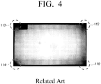
- FIG. 4 is a brightness photograph of an illuminating apparatus in the related art.
- the illuminating apparatus of FIG. 4 does not have corner side extending portions.
- FIG. 5 is a brightness photograph of the illuminating apparatus illustrated in FIG. 1 .
- the dark regions appear in the four corner areas 113', 114', 115', and 116'.
- the dark regions do not appear substantially in the four corner areas 113, 114, 115, and 116.
- the light emitting unit 120 consists of only one light emitting module 120.
- the light emitting unit may be configured with two or more light emitting modules. Such alternative illuminating apparatuses are illustrated in FIGS. 6 , 7 , and 8 .
- FIG. 6 that is a view similar to FIG. 2 , and illustrates a plan view of an illuminating apparatus according to a second exemplary embodiment will be described.
- the illuminating apparatus 200 similar to the illuminating apparatus 100 according to the first exemplary embodiment, as described above, the illuminating apparatus 200 according to the second exemplary embodiment includes a support member 210 and a light emitting unit 220.
- the support member 210 is the same as the support member 110 of the first exemplary embodiment, as described above.
- the light emitting unit 220 consists of two light emitting modules 250 and 260, and thus is distinguished from the light emitting unit 120 of the first exemplary embodiment, as described above.
- the light emitting unit 220 consists of a first light emitting module 250 and a second light emitting module 260.
- the first light emitting module 250 includes a first body portion 251 that is extended along the lengthwise direction (X direction in FIG. 6 ) of a light source support member 211, a first corner side extending portion 253 that is extended from one end 251a of the first body portion 251 to a first corner area 213 of the light source support member 211, and a second corner side extending portion 255 that is extended from the other end 251b of the first body portion 251 to a second corner area 215 of the light source support member 211.
- the second light emitting module 260 includes a second body portion 261 that is extended along the lengthwise direction (X direction in FIG. 6 ) of the light source support member 211, a third corner side extending portion 264 that is extended from one end 261a of the second body portion 261 to a third corner area 214 of the light source support member 211, and a fourth corner side extending portion 266 that is extended from the other end 261b of the second body portion 261 to a fourth corner area 216 of the light source support member 211.
- the illuminating apparatus 200 is equipped with the first and second corner side extending portions 253 and 255 that configure a portion of the first light emitting module 250 and are extended toward the first and second corner areas 213 and 215, and the third and fourth corner side extending portions 264 and 266 that configure a portion of the second light emitting module 260 and are extended toward the third and fourth corner areas 214 and 216, thereby preventing dark regions from appearing in four corner areas 213, 214, 215, and 216 of the support member 210.
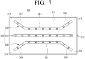
- FIG. 7 that is a view similar to FIG. 6 , and illustrates a plan view of an illuminating apparatus according to a third exemplary embodiment will be described.
- an illuminating apparatus 300 similar to the illuminating apparatus 200 according to the second exemplary embodiment, as described above, an illuminating apparatus 300 according to the third exemplary embodiment includes a support member 310 and a light emitting unit 320.
- the support member 310 is the same as the support member 210 of the second exemplary embodiment illustrated in FIG. 6 .
- the light emitting unit 320 additionally includes a third light emitting module 370 arranged between a first light emitting module 350 and a second light emitting module 360, and thus is distinguished from the light emitting unit 220 of the second exemplary embodiment of FIG. 6 , as described above.
- the third light emitting module 370 is arranged parallel to a first body portion 351 of the first light emitting module 350 and a second body portion 361 of the second light emitting module 360, namely along the lengthwise direction of the light source support member 311, but is not provided with any corner side extending portions, unlike the first and second light emitting modules 350 and 360.
- the illuminating apparatus 300 is equipped with first and second corner side extending portions 353 and 355 that configure a portion of the first light emitting module 350 and are extended toward first and second corner areas 313 and 315, and third and fourth corner side extending portions 364 and 366 that configure a portion of the second light emitting module 360 and are extended toward third and fourth corner areas 314 and 316, thereby preventing dark regions from appearing in the four corner areas 313, 314, 315, and 316 of the support member 310.
- FIG. 8 that is a view similar to FIG. 7 , and illustrates a plan view of an illuminating apparatus according to a fourth exemplary embodiment of the present disclosure will be described.
- an illuminating apparatus 400 similar to the illuminating apparatus 300 according to the third exemplary embodiment, as described above, an illuminating apparatus 400 according to the fourth exemplary embodiment of the present disclosure includes a support member 410 and a light emitting unit 420.
- the support member 410 is the same as the support member 310 of the third exemplary embodiment illustrated in FIG. 7 .
- the light emitting unit 420 additionally includes a fourth light emitting module 480 as well as a third light emitting module 470 arranged between a first light emitting module 450 and a second light emitting module 460, and thus is distinguished from the light emitting unit 320 of the third exemplary embodiment of FIG. 7 , as described above.
- the fourth light emitting module 480 is arranged along the lengthwise direction of the light source support member 411, but is not provided with any corner side extending portions.
- the illuminating apparatus 400 is equipped with first and second corner side extending portions 453 and 455 that configure a portion of the first light emitting module 450 and are extended toward first and second corner areas 413 and 415, and third and fourth corner side extending portions 464 and 466 that configure a portion of the second light emitting module 460 and are extended toward third and fourth corner areas 414 and 416, thereby preventing dark regions from appearing in four corner areas 413, 414, 415, and 416 of the support member 410.
- the illuminating apparatuses 100, 200, 300, and 400, as described above, may be applied to various electronic apparatuses such as lighting devices, promotional signboards, and display apparatuses.
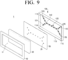
- FIG. 9 that illustrates schematically an exploded perspective view of a liquid crystal display 1 to which the illuminating apparatus 100 according to the first exemplary embodiment is applied will be described.
- the liquid crystal display 1 includes the illuminating apparatus 100, a cover member 10, a liquid crystal panel 20, and a reflection sheet 30.
- the illuminating apparatus 100 includes the support member 110 and the light emitting unit 120.
- support member 110 In the field of displays, such support member 110 is often referred to as a bottom chassis.
- the light emitting unit 120 is equipped with four corner side extending portions 123, 124, 125, and 126 to prevent dark regions from appearing in the four corner areas 113, 114, 115, and 116 of the support member 110.
- the cover member 10 is coupled to the support member 110 so as to package internal components such as the liquid crystal panel 20, etc. as a single apparatus.
- the cover member 10 is provided with a rectangular opening 11 that lets videos, which the liquid crystal panel 20 displays, to be visible outside the cover member 10. In the field of display, such cover member 10 is often referred to as a top chassis.
- the liquid crystal panel 20 is disposed between the support member 110 and the cover member 10, and displays videos by using light that the illuminating apparatus 100 provides by a direct lighting method.
- the reflection sheet 30 is attached to an inner surface of the support member 110 to increase the optical efficiency of the light emitting unit 120.
- the reflection sheet 30 is arranged to cover the light emitting unit 120 disposed in the support member 110, but light source packages 140 of the light emitting unit 120 are exposed through a plurality of exposure holes 31 formed in the reflection sheet 30.
- FIG. 10 is a perspective view illustrating an illuminating apparatus according to a fifth exemplary embodiment
- FIG. 11 is a sectional view illustrating the illuminating apparatus of FIG. 10 taken along a line II-II in FIG. 10 .
- the illuminating apparatus 500 includes a support member 510 and a light emitting unit 520.
- the support member 510 is formed in a shape of a box that has a shallow depth and an open top side.
- the support member 510 consists of a light source support member 511 formed in the form of a concave curved plate and a side wall 512 extending vertically from an edge of the light source support member 511.
- the light source support member 511 supports a light emitting unit 520 disposed on a surface 511a of the light source support member 511, and the side wall 512 forms an inner space of the illuminating apparatus 500.
- the light emitting unit 520 consists of three light emitting modules 550, 560, and 570.
- the number of the light emitting modules configuring the light emitting unit 520 may be selected differently such as, for example, 1, 3, 4, etc.
- a first light emitting module 550, a second light emitting module 560, and a third light emitting module 570 have the same structure as each other.
- the first light emitting module 550 among the three light emitting modules 550, 560, and 570 may include a printed circuit board (PCB) 530 of a strip shape and a plurality of light source packages 540 that is mounted on the printed circuit board 530 and generates light.
- the printed circuit board 530 supports the plurality of light source packages 540, and delivers power being supplied from a power source (not illustrated) to the light source packages 540.
- the light source packages 540 are the same as the light source packages 140 (see FIGS. 1 , 2 and 3 ) of the illuminating apparatus 100, as described above, therefore, description thereof will be omitted.
- the light source support member 511 of the support member 510 has the shape of a curved plate, the light source support member 511 has non-uniform depth along the lengthwise direction (X direction in FIG. 11 ) of the support member 510.
- 'R' represents a horizontal imaginary reference plane placed on the support member 510
- 'd' represents a depth from the reference plane R to any point on the light source support member 511. From FIG. 11 it can be seen that as the point goes closer to the center of the light source support member 511 in the lengthwise direction (X direction) of the support member 510, the depth d of the point is deeper. Accordingly, the light source support member 511 has the maximum depth dmax in the central area M thereof.
- the depth d of the light source support member 111 is uniform in contrast to the present exemplary embodiment, recycling or mixing of light occurs relatively less in the central area M of the light source support member 111 that is far away from the side wall 512, so light uniformity may be reduced relatively.
- the reduction of the light uniformity may result in mura (i.e., unevenness, irregularity, lack of uniformity, or nonuniformity of brightness across a display) in the central area M.
- the support member 110 is designed to have the maximum depth in the central area M of the light source support member 111, mixture of light in the central area M may be increased so that the light uniformity in the central area M is improved. As a result, generation of the mura that can occur when the light uniformity is degraded may be prevented.
- the illuminating apparatus 600 includes a support member 610 consisting of a light source support member 611 and a side wall 612.
- the light source support member 611 has a plate shape that is bent at a bending line L to be a first support portion 611A and a second support portion 611B.
- the first and second support portions 611A and 611B bounded by the bending line L are arranged in an obtuse angle with respect to each other.
- Three light emitting modules 650A, 660A, and 670A mounted on the first support portion 611A and three light emitting modules 650B, 660B, and 670B mounted on the second support portion 611B configure the light emitting unit.
- the light source support member 611 Since the light source support member 611 has a bent shape, the light source support member 611 has non-uniform depth and the maximum depth in the central area M thereof. Therefore, as with the aforementioned illuminating apparatus 500, in the case of the illuminating apparatus 600 according to the sixth exemplary embodiment, the light uniformity in the central area M is improved so that appearance of the mura in the central area M may be prevented.
- the illuminating apparatus 700 includes a support member 710 consisting of a light source support member 711 and a side wall 712.
- the light source support member 711 has a plate shape that is bent at two bending lines L1 and L2 to be a first support portion 711A, a second support portion 711B, and a third support portion 711C.
- the first and third support portions 711A and 711C bounded by the first bending line L1 are arranged in an obtuse angle with respect to each other, and the second and third support portions 711B and 711C bounded by the second bending line L2 are arranged in an obtuse angle with respect to each other.
- the light source support member 711 Since the light source support member 711 has a bent shape, the light source support member 711 has non-uniform depth and the maximum depth in the central area M thereof. Therefore, as with the aforementioned illuminating apparatus 500, in the case of the illuminating apparatus 700 according to the seventh exemplary embodiment, the light uniformity in the central area M is improved so that appearance of mura in the central area M may be prevented.
- the illuminating apparatuses 500, 600, and 700 may be applied to various electronic apparatuses such as lighting devices, promotional signboards, and display apparatuses.
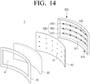
- FIG. 14 that illustrates schematically an exploded perspective view of a liquid crystal display 2 to which the illuminating apparatus 500 according to the fifth exemplary embodiment is applied will be described.
- the liquid crystal display 2 includes the illuminating apparatus 500, a cover member 40, a liquid crystal panel 50, and a reflection sheet 60.
- the illuminating apparatus 500 includes the support member 510 and the light emitting unit 520. Because the light source support member 511 of the support member 510 is formed in the curved plate, the support member 110 has the maximum depth in the central area M (see FIG. 11 ) thereof.
- the cover member 40, the liquid crystal panel 50, and the reflection sheet 60 are similar to the cover member 10, liquid crystal panel 20, and reflection sheet 30 illustrated in FIG. 9 , respectively. However, each of the cover member 40, the liquid crystal panel 50, and the reflection sheet 60 is bent corresponding to the shape of the light source support member 511 of the support member 510, so it takes a shape having curvature.
- the liquid crystal display 2 corresponds to a kind of curved display.
- Reference number 61 refers to a plurality of exposure holes for exposing the light source packages 540.
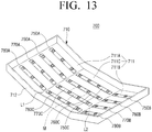
- the illuminating apparatus 800 includes a support member 810 and a light emitting unit 820.
- the support member 810 consists of the light source support member 811 and a side wall 812. As with the support member 510 illustrated in FIG. 10 , the light source support member 811 of the support member 810 has a curved plate shape and the maximum depth in the central area M thereof. Accordingly, in the illuminating apparatus 800 according to the present exemplary embodiment, mura may be prevented from appearing in the central area M of the light source support member 811.
- the light emitting unit 820 consists of three light emitting modules 850, 860, and 870.
- a first light emitting module 850 includes two corner side extending portions 853 and 855 extended towards two corner areas 813 and 815 of the light source support member 811
- a second light emitting module 860 includes the other two corner side extending portions 864 and 866 extended towards the other two corner areas 814 and 816 of the light source support member 811. Because the light emitting unit 820 is equipped with a total of four corner side extending portions 853, 855, 864, and 866, dark regions may be prevented from appearing in the four corner areas 813, 814, 815, and 816.
- the illuminating apparatus 800 As described above, with the illuminating apparatus 800 according to the eighth exemplary embodiment, because appearance of mura in the central area M of the support member 810 and appearance of dark regions in the four corner areas 813, 814, 815, and 816 of the support member 810 are prevented, light uniformity of the illuminating apparatus 800 may be improved.
Applications Claiming Priority (1)
| Application Number | Priority Date | Filing Date | Title |
|---|---|---|---|
| KR1020130063619A KR101474734B1 (ko) | 2013-06-03 | 2013-06-03 | 발광 장치 및 그것을 구비한 액정 디스플레이 |
Publications (3)
| Publication Number | Publication Date |
|---|---|
| EP2811336A2 EP2811336A2 (en) | 2014-12-10 |
| EP2811336A3 EP2811336A3 (en) | 2015-02-25 |
| EP2811336B1 true EP2811336B1 (en) | 2018-12-12 |
Family
ID=50070361
Family Applications (1)
| Application Number | Title | Priority Date | Filing Date |
|---|---|---|---|
| EP14153933.8A Active EP2811336B1 (en) | 2013-06-03 | 2014-02-05 | Illuminating apparatus and liquid crystal display having the same |
Country Status (6)
| Country | Link |
|---|---|
| US (2) | US9733516B2 (zh) |
| EP (1) | EP2811336B1 (zh) |
| JP (1) | JP2014236218A (zh) |
| KR (1) | KR101474734B1 (zh) |
| CN (1) | CN104214603B (zh) |
| WO (1) | WO2014196704A1 (zh) |
Families Citing this family (15)
| Publication number | Priority date | Publication date | Assignee | Title |
|---|---|---|---|---|
| CN104132316A (zh) | 2014-07-23 | 2014-11-05 | 苏州吉视电子科技有限公司 | 一种工业检测用led光源 |
| TWM496780U (zh) * | 2014-09-15 | 2015-03-01 | Innolux Corp | 電子顯示裝置 |
| KR102185235B1 (ko) * | 2014-10-10 | 2020-12-02 | 삼성디스플레이 주식회사 | 표시 장치 |
| KR20160073721A (ko) * | 2014-12-17 | 2016-06-27 | 주식회사 토비스 | 절곡된 곡면형태의 백플레이트를 포함하는 백라이트유닛, 및 이를 이용한 곡면형 디스플레이장치 |
| KR102304666B1 (ko) * | 2014-12-30 | 2021-09-24 | 엘지디스플레이 주식회사 | 곡면 프레임 및 이를 구비한 곡면 표시장치 |
| KR102320143B1 (ko) * | 2015-02-13 | 2021-11-02 | 삼성디스플레이 주식회사 | 표시장치 |
| TWI560500B (en) * | 2015-03-20 | 2016-12-01 | Au Optronics Corp | Backlight module having brightness enhancement design at periphery of display surface |
| KR102339539B1 (ko) * | 2015-05-08 | 2021-12-16 | 삼성전자주식회사 | 디스플레이 장치 |
| CN105546407A (zh) * | 2015-12-30 | 2016-05-04 | 太仓卡斯特姆新材料有限公司 | 一种适用于宽板非常规的灯条 |
| CN107436509A (zh) * | 2016-05-27 | 2017-12-05 | 鸿富锦精密工业(深圳)有限公司 | 背光模组 |
| KR101995972B1 (ko) * | 2016-12-21 | 2019-07-03 | 주식회사 토비스 | 절곡된 곡면형태의 백플레이트를 포함하는 백라이트유닛, 및 이를 이용한 곡면형 디스플레이장치 |
| KR102314920B1 (ko) * | 2017-08-08 | 2021-10-20 | 엘지전자 주식회사 | 디스플레이 디바이스 |
| CN109491146B (zh) * | 2019-01-15 | 2022-04-26 | 高创(苏州)电子有限公司 | 发光模组及其制造方法、直下式背光模组及显示装置 |
| CN109782489B (zh) * | 2019-03-28 | 2021-10-22 | 京东方科技集团股份有限公司 | 一种背光模组及显示装置 |
| KR102546988B1 (ko) * | 2021-06-30 | 2023-06-22 | 엘지전자 주식회사 | 디스플레이 디바이스 |
Family Cites Families (13)
| Publication number | Priority date | Publication date | Assignee | Title |
|---|---|---|---|---|
| US6712481B2 (en) | 1995-06-27 | 2004-03-30 | Solid State Opto Limited | Light emitting panel assemblies |
| JPH11126029A (ja) | 1997-10-22 | 1999-05-11 | Yazaki Corp | 表示器 |
| JP4172455B2 (ja) | 2004-10-08 | 2008-10-29 | ソニー株式会社 | バックライト用光源ユニット、液晶表示用バックライト装置及び透過型カラー液晶表示装置 |
| DE102006002275A1 (de) * | 2005-01-19 | 2006-07-20 | Osram Opto Semiconductors Gmbh | Beleuchtungseinrichtung |
| KR101134301B1 (ko) * | 2005-02-28 | 2012-04-13 | 엘지디스플레이 주식회사 | 엘이디 백라이트어셈블리 및 이를 이용한 액정표시장치모듈 |
| JP2007171681A (ja) * | 2005-12-22 | 2007-07-05 | Infovision Optoelectronics Holdings Ltd | 湾曲液晶表示装置に用いるバックライト及び湾曲液晶表示装置 |
| JP2007317423A (ja) * | 2006-05-24 | 2007-12-06 | Harison Toshiba Lighting Corp | バックライトユニット |
| TWI353473B (en) | 2006-06-06 | 2011-12-01 | Au Optronics Corp | Backlight unit and liquid crystal display |
| KR101261881B1 (ko) * | 2006-06-09 | 2013-05-06 | 엘지디스플레이 주식회사 | 발광다이오드 어셈블리 및 이를 포함하는 액정표시장치모듈 |
| WO2011004683A1 (ja) * | 2009-07-09 | 2011-01-13 | シャープ株式会社 | 照明装置、表示装置、テレビ受信装置及び照明装置の製造方法 |
| KR101575360B1 (ko) * | 2009-09-04 | 2015-12-07 | 엘지이노텍 주식회사 | 백라이트 유닛 및 이를 이용한 액정표시장치 |
| JP5372053B2 (ja) | 2011-03-10 | 2013-12-18 | シャープ株式会社 | 面光源装置および液晶表示装置 |
| KR101251869B1 (ko) * | 2012-10-30 | 2013-04-12 | (주)휴먼라이텍 | 엘이디 조명등 |
-
2013
- 2013-06-03 KR KR1020130063619A patent/KR101474734B1/ko active IP Right Grant
- 2013-12-03 WO PCT/KR2013/011124 patent/WO2014196704A1/en active Application Filing
-
2014
- 2014-02-04 US US14/171,850 patent/US9733516B2/en active Active
- 2014-02-05 EP EP14153933.8A patent/EP2811336B1/en active Active
- 2014-03-11 JP JP2014047723A patent/JP2014236218A/ja active Pending
- 2014-05-28 CN CN201410230947.1A patent/CN104214603B/zh active Active
-
2017
- 2017-07-12 US US15/647,822 patent/US10133119B2/en active Active
Non-Patent Citations (1)
| Title |
|---|
| None * |
Also Published As
| Publication number | Publication date |
|---|---|
| CN104214603A (zh) | 2014-12-17 |
| US20170307938A1 (en) | 2017-10-26 |
| KR101474734B1 (ko) | 2014-12-22 |
| JP2014236218A (ja) | 2014-12-15 |
| WO2014196704A1 (en) | 2014-12-11 |
| US10133119B2 (en) | 2018-11-20 |
| KR20140142059A (ko) | 2014-12-11 |
| US9733516B2 (en) | 2017-08-15 |
| EP2811336A2 (en) | 2014-12-10 |
| CN104214603B (zh) | 2018-04-03 |
| US20140354914A1 (en) | 2014-12-04 |
| EP2811336A3 (en) | 2015-02-25 |
Similar Documents
| Publication | Publication Date | Title |
|---|---|---|
| EP2811336B1 (en) | Illuminating apparatus and liquid crystal display having the same | |
| US10845646B2 (en) | Display module and display apparatus having the same | |
| US9354385B2 (en) | Curved display apparatus | |
| CN101097349B (zh) | 背光组件及采用其的液晶显示器件 | |
| US8636401B2 (en) | Backlight unit and liquid crystal display having the same | |
| US20070253219A1 (en) | Backlight assembly and liquid crystal display device having the same | |
| US9823508B2 (en) | Display device | |
| JP2004079488A (ja) | Ledバックライトユニットおよび液晶表示装置 | |
| EP3073318B1 (en) | Display device | |
| KR102600981B1 (ko) | 디스플레이 장치 | |
| EP2863255B1 (en) | Liquid crystal display apparatus | |
| US10078178B2 (en) | Flexible printed circuit board, back light unit and liquid crystal display device using the same | |
| TWI420202B (zh) | 側面入光式背光模組 | |
| US20150261043A1 (en) | Display apparatus | |
| KR20140146829A (ko) | 액정 디스플레이 장치 | |
| US10054808B2 (en) | Display chassis and display device comprising the same | |
| EP2592469A1 (en) | Liquid crystal panel assembly and image display apparatus having the same | |
| US9028126B2 (en) | LED light bar and side-edge backlight module using same | |
| KR20090053631A (ko) | 백라이트 유닛, 이를 구비한 액정표시장치 및 그 제조방법 | |
| KR102298380B1 (ko) | 백라이트 유닛 및 이를 포함하는 액정표시장치 | |
| EP2523040B1 (en) | Display with a light guide plate |
Legal Events
| Date | Code | Title | Description |
|---|---|---|---|
| PUAI | Public reference made under article 153(3) epc to a published international application that has entered the european phase |
Free format text: ORIGINAL CODE: 0009012 |
|
| 17P | Request for examination filed |
Effective date: 20140205 |
|
| AK | Designated contracting states |
Kind code of ref document: A2 Designated state(s): AL AT BE BG CH CY CZ DE DK EE ES FI FR GB GR HR HU IE IS IT LI LT LU LV MC MK MT NL NO PL PT RO RS SE SI SK SM TR |
|
| AX | Request for extension of the european patent |
Extension state: BA ME |
|
| R17P | Request for examination filed (corrected) |
Effective date: 20141208 |
|
| RBV | Designated contracting states (corrected) |
Designated state(s): AL AT BE BG CH CY CZ DE DK EE ES FI FR GB GR HR HU IE IS IT LI LT LU LV MC MK MT NL NO PL PT RO RS SE SI SK SM TR |
|
| PUAL | Search report despatched |
Free format text: ORIGINAL CODE: 0009013 |
|
| AK | Designated contracting states |
Kind code of ref document: A3 Designated state(s): AL AT BE BG CH CY CZ DE DK EE ES FI FR GB GR HR HU IE IS IT LI LT LU LV MC MK MT NL NO PL PT RO RS SE SI SK SM TR |
|
| AX | Request for extension of the european patent |
Extension state: BA ME |
|
| RIC1 | Information provided on ipc code assigned before grant |
Ipc: G02F 1/1335 20060101AFI20150122BHEP |
|
| GRAP | Despatch of communication of intention to grant a patent |
Free format text: ORIGINAL CODE: EPIDOSNIGR1 |
|
| STAA | Information on the status of an ep patent application or granted ep patent |
Free format text: STATUS: GRANT OF PATENT IS INTENDED |
|
| INTG | Intention to grant announced |
Effective date: 20180706 |
|
| GRAS | Grant fee paid |
Free format text: ORIGINAL CODE: EPIDOSNIGR3 |
|
| GRAA | (expected) grant |
Free format text: ORIGINAL CODE: 0009210 |
|
| STAA | Information on the status of an ep patent application or granted ep patent |
Free format text: STATUS: THE PATENT HAS BEEN GRANTED |
|
| AK | Designated contracting states |
Kind code of ref document: B1 Designated state(s): AL AT BE BG CH CY CZ DE DK EE ES FI FR GB GR HR HU IE IS IT LI LT LU LV MC MK MT NL NO PL PT RO RS SE SI SK SM TR |
|
| REG | Reference to a national code |
Ref country code: GB Ref legal event code: FG4D |
|
| REG | Reference to a national code |
Ref country code: CH Ref legal event code: EP |
|
| REG | Reference to a national code |
Ref country code: AT Ref legal event code: REF Ref document number: 1076789 Country of ref document: AT Kind code of ref document: T Effective date: 20181215 |
|
| REG | Reference to a national code |
Ref country code: DE Ref legal event code: R096 Ref document number: 602014037711 Country of ref document: DE |
|
| REG | Reference to a national code |
Ref country code: IE Ref legal event code: FG4D |
|
| REG | Reference to a national code |
Ref country code: NL Ref legal event code: FP |
|
| REG | Reference to a national code |
Ref country code: LT Ref legal event code: MG4D |
|
| PG25 | Lapsed in a contracting state [announced via postgrant information from national office to epo] |
Ref country code: LV Free format text: LAPSE BECAUSE OF FAILURE TO SUBMIT A TRANSLATION OF THE DESCRIPTION OR TO PAY THE FEE WITHIN THE PRESCRIBED TIME-LIMIT Effective date: 20181212 Ref country code: LT Free format text: LAPSE BECAUSE OF FAILURE TO SUBMIT A TRANSLATION OF THE DESCRIPTION OR TO PAY THE FEE WITHIN THE PRESCRIBED TIME-LIMIT Effective date: 20181212 Ref country code: BG Free format text: LAPSE BECAUSE OF FAILURE TO SUBMIT A TRANSLATION OF THE DESCRIPTION OR TO PAY THE FEE WITHIN THE PRESCRIBED TIME-LIMIT Effective date: 20190312 Ref country code: ES Free format text: LAPSE BECAUSE OF FAILURE TO SUBMIT A TRANSLATION OF THE DESCRIPTION OR TO PAY THE FEE WITHIN THE PRESCRIBED TIME-LIMIT Effective date: 20181212 Ref country code: HR Free format text: LAPSE BECAUSE OF FAILURE TO SUBMIT A TRANSLATION OF THE DESCRIPTION OR TO PAY THE FEE WITHIN THE PRESCRIBED TIME-LIMIT Effective date: 20181212 Ref country code: FI Free format text: LAPSE BECAUSE OF FAILURE TO SUBMIT A TRANSLATION OF THE DESCRIPTION OR TO PAY THE FEE WITHIN THE PRESCRIBED TIME-LIMIT Effective date: 20181212 Ref country code: NO Free format text: LAPSE BECAUSE OF FAILURE TO SUBMIT A TRANSLATION OF THE DESCRIPTION OR TO PAY THE FEE WITHIN THE PRESCRIBED TIME-LIMIT Effective date: 20190312 |
|
| REG | Reference to a national code |
Ref country code: AT Ref legal event code: MK05 Ref document number: 1076789 Country of ref document: AT Kind code of ref document: T Effective date: 20181212 |
|
| PG25 | Lapsed in a contracting state [announced via postgrant information from national office to epo] |
Ref country code: GR Free format text: LAPSE BECAUSE OF FAILURE TO SUBMIT A TRANSLATION OF THE DESCRIPTION OR TO PAY THE FEE WITHIN THE PRESCRIBED TIME-LIMIT Effective date: 20190313 Ref country code: RS Free format text: LAPSE BECAUSE OF FAILURE TO SUBMIT A TRANSLATION OF THE DESCRIPTION OR TO PAY THE FEE WITHIN THE PRESCRIBED TIME-LIMIT Effective date: 20181212 Ref country code: AL Free format text: LAPSE BECAUSE OF FAILURE TO SUBMIT A TRANSLATION OF THE DESCRIPTION OR TO PAY THE FEE WITHIN THE PRESCRIBED TIME-LIMIT Effective date: 20181212 Ref country code: SE Free format text: LAPSE BECAUSE OF FAILURE TO SUBMIT A TRANSLATION OF THE DESCRIPTION OR TO PAY THE FEE WITHIN THE PRESCRIBED TIME-LIMIT Effective date: 20181212 |
|
| PG25 | Lapsed in a contracting state [announced via postgrant information from national office to epo] |
Ref country code: IT Free format text: LAPSE BECAUSE OF FAILURE TO SUBMIT A TRANSLATION OF THE DESCRIPTION OR TO PAY THE FEE WITHIN THE PRESCRIBED TIME-LIMIT Effective date: 20181212 Ref country code: CZ Free format text: LAPSE BECAUSE OF FAILURE TO SUBMIT A TRANSLATION OF THE DESCRIPTION OR TO PAY THE FEE WITHIN THE PRESCRIBED TIME-LIMIT Effective date: 20181212 Ref country code: PT Free format text: LAPSE BECAUSE OF FAILURE TO SUBMIT A TRANSLATION OF THE DESCRIPTION OR TO PAY THE FEE WITHIN THE PRESCRIBED TIME-LIMIT Effective date: 20190412 Ref country code: PL Free format text: LAPSE BECAUSE OF FAILURE TO SUBMIT A TRANSLATION OF THE DESCRIPTION OR TO PAY THE FEE WITHIN THE PRESCRIBED TIME-LIMIT Effective date: 20181212 |
|
| PG25 | Lapsed in a contracting state [announced via postgrant information from national office to epo] |
Ref country code: SK Free format text: LAPSE BECAUSE OF FAILURE TO SUBMIT A TRANSLATION OF THE DESCRIPTION OR TO PAY THE FEE WITHIN THE PRESCRIBED TIME-LIMIT Effective date: 20181212 Ref country code: IS Free format text: LAPSE BECAUSE OF FAILURE TO SUBMIT A TRANSLATION OF THE DESCRIPTION OR TO PAY THE FEE WITHIN THE PRESCRIBED TIME-LIMIT Effective date: 20190412 Ref country code: RO Free format text: LAPSE BECAUSE OF FAILURE TO SUBMIT A TRANSLATION OF THE DESCRIPTION OR TO PAY THE FEE WITHIN THE PRESCRIBED TIME-LIMIT Effective date: 20181212 Ref country code: SM Free format text: LAPSE BECAUSE OF FAILURE TO SUBMIT A TRANSLATION OF THE DESCRIPTION OR TO PAY THE FEE WITHIN THE PRESCRIBED TIME-LIMIT Effective date: 20181212 Ref country code: EE Free format text: LAPSE BECAUSE OF FAILURE TO SUBMIT A TRANSLATION OF THE DESCRIPTION OR TO PAY THE FEE WITHIN THE PRESCRIBED TIME-LIMIT Effective date: 20181212 |
|
| REG | Reference to a national code |
Ref country code: DE Ref legal event code: R097 Ref document number: 602014037711 Country of ref document: DE |
|
| REG | Reference to a national code |
Ref country code: CH Ref legal event code: PL |
|
| PLBE | No opposition filed within time limit |
Free format text: ORIGINAL CODE: 0009261 |
|
| STAA | Information on the status of an ep patent application or granted ep patent |
Free format text: STATUS: NO OPPOSITION FILED WITHIN TIME LIMIT |
|
| PG25 | Lapsed in a contracting state [announced via postgrant information from national office to epo] |
Ref country code: MC Free format text: LAPSE BECAUSE OF FAILURE TO SUBMIT A TRANSLATION OF THE DESCRIPTION OR TO PAY THE FEE WITHIN THE PRESCRIBED TIME-LIMIT Effective date: 20181212 Ref country code: SI Free format text: LAPSE BECAUSE OF FAILURE TO SUBMIT A TRANSLATION OF THE DESCRIPTION OR TO PAY THE FEE WITHIN THE PRESCRIBED TIME-LIMIT Effective date: 20181212 Ref country code: LU Free format text: LAPSE BECAUSE OF NON-PAYMENT OF DUE FEES Effective date: 20190205 Ref country code: AT Free format text: LAPSE BECAUSE OF FAILURE TO SUBMIT A TRANSLATION OF THE DESCRIPTION OR TO PAY THE FEE WITHIN THE PRESCRIBED TIME-LIMIT Effective date: 20181212 Ref country code: DK Free format text: LAPSE BECAUSE OF FAILURE TO SUBMIT A TRANSLATION OF THE DESCRIPTION OR TO PAY THE FEE WITHIN THE PRESCRIBED TIME-LIMIT Effective date: 20181212 |
|
| 26N | No opposition filed |
Effective date: 20190913 |
|
| REG | Reference to a national code |
Ref country code: BE Ref legal event code: MM Effective date: 20190228 |
|
| GBPC | Gb: european patent ceased through non-payment of renewal fee |
Effective date: 20190312 |
|
| REG | Reference to a national code |
Ref country code: IE Ref legal event code: MM4A |
|
| PG25 | Lapsed in a contracting state [announced via postgrant information from national office to epo] |
Ref country code: CH Free format text: LAPSE BECAUSE OF NON-PAYMENT OF DUE FEES Effective date: 20190228 Ref country code: LI Free format text: LAPSE BECAUSE OF NON-PAYMENT OF DUE FEES Effective date: 20190228 |
|
| PG25 | Lapsed in a contracting state [announced via postgrant information from national office to epo] |
Ref country code: GB Free format text: LAPSE BECAUSE OF NON-PAYMENT OF DUE FEES Effective date: 20190312 Ref country code: IE Free format text: LAPSE BECAUSE OF NON-PAYMENT OF DUE FEES Effective date: 20190205 |
|
| PG25 | Lapsed in a contracting state [announced via postgrant information from national office to epo] |
Ref country code: FR Free format text: LAPSE BECAUSE OF NON-PAYMENT OF DUE FEES Effective date: 20190212 Ref country code: BE Free format text: LAPSE BECAUSE OF NON-PAYMENT OF DUE FEES Effective date: 20190228 |
|
| PG25 | Lapsed in a contracting state [announced via postgrant information from national office to epo] |
Ref country code: TR Free format text: LAPSE BECAUSE OF FAILURE TO SUBMIT A TRANSLATION OF THE DESCRIPTION OR TO PAY THE FEE WITHIN THE PRESCRIBED TIME-LIMIT Effective date: 20181212 |
|
| PG25 | Lapsed in a contracting state [announced via postgrant information from national office to epo] |
Ref country code: MT Free format text: LAPSE BECAUSE OF NON-PAYMENT OF DUE FEES Effective date: 20190205 |
|
| PG25 | Lapsed in a contracting state [announced via postgrant information from national office to epo] |
Ref country code: CY Free format text: LAPSE BECAUSE OF FAILURE TO SUBMIT A TRANSLATION OF THE DESCRIPTION OR TO PAY THE FEE WITHIN THE PRESCRIBED TIME-LIMIT Effective date: 20181212 |
|
| PG25 | Lapsed in a contracting state [announced via postgrant information from national office to epo] |
Ref country code: HU Free format text: LAPSE BECAUSE OF FAILURE TO SUBMIT A TRANSLATION OF THE DESCRIPTION OR TO PAY THE FEE WITHIN THE PRESCRIBED TIME-LIMIT; INVALID AB INITIO Effective date: 20140205 |
|
| PG25 | Lapsed in a contracting state [announced via postgrant information from national office to epo] |
Ref country code: MK Free format text: LAPSE BECAUSE OF FAILURE TO SUBMIT A TRANSLATION OF THE DESCRIPTION OR TO PAY THE FEE WITHIN THE PRESCRIBED TIME-LIMIT Effective date: 20181212 |
|
| PGFP | Annual fee paid to national office [announced via postgrant information from national office to epo] |
Ref country code: DE Payment date: 20230119 Year of fee payment: 10 |
|
| PGFP | Annual fee paid to national office [announced via postgrant information from national office to epo] |
Ref country code: NL Payment date: 20230120 Year of fee payment: 10 |
|
| PGFP | Annual fee paid to national office [announced via postgrant information from national office to epo] |
Ref country code: NL Payment date: 20240123 Year of fee payment: 11 |