EP2811166B1 - Metalschmelzpumpe und Notfallabpumpen von Metallschmelze - Google Patents
Metalschmelzpumpe und Notfallabpumpen von Metallschmelze Download PDFInfo
- Publication number
- EP2811166B1 EP2811166B1 EP14171529.2A EP14171529A EP2811166B1 EP 2811166 B1 EP2811166 B1 EP 2811166B1 EP 14171529 A EP14171529 A EP 14171529A EP 2811166 B1 EP2811166 B1 EP 2811166B1
- Authority
- EP
- European Patent Office
- Prior art keywords
- pump
- metal
- impeller
- molten metal
- shaft
- Prior art date
- Legal status (The legal status is an assumption and is not a legal conclusion. Google has not performed a legal analysis and makes no representation as to the accuracy of the status listed.)
- Active
Links
Images




Classifications
-
- F—MECHANICAL ENGINEERING; LIGHTING; HEATING; WEAPONS; BLASTING
- F04—POSITIVE - DISPLACEMENT MACHINES FOR LIQUIDS; PUMPS FOR LIQUIDS OR ELASTIC FLUIDS
- F04D—NON-POSITIVE-DISPLACEMENT PUMPS
- F04D7/00—Pumps adapted for handling specific fluids, e.g. by selection of specific materials for pumps or pump parts
- F04D7/02—Pumps adapted for handling specific fluids, e.g. by selection of specific materials for pumps or pump parts of centrifugal type
- F04D7/06—Pumps adapted for handling specific fluids, e.g. by selection of specific materials for pumps or pump parts of centrifugal type the fluids being hot or corrosive, e.g. liquid metals
- F04D7/065—Pumps adapted for handling specific fluids, e.g. by selection of specific materials for pumps or pump parts of centrifugal type the fluids being hot or corrosive, e.g. liquid metals for liquid metal
-
- F—MECHANICAL ENGINEERING; LIGHTING; HEATING; WEAPONS; BLASTING
- F04—POSITIVE - DISPLACEMENT MACHINES FOR LIQUIDS; PUMPS FOR LIQUIDS OR ELASTIC FLUIDS
- F04D—NON-POSITIVE-DISPLACEMENT PUMPS
- F04D13/00—Pumping installations or systems
- F04D13/02—Units comprising pumps and their driving means
- F04D13/06—Units comprising pumps and their driving means the pump being electrically driven
- F04D13/08—Units comprising pumps and their driving means the pump being electrically driven for submerged use
-
- F—MECHANICAL ENGINEERING; LIGHTING; HEATING; WEAPONS; BLASTING
- F04—POSITIVE - DISPLACEMENT MACHINES FOR LIQUIDS; PUMPS FOR LIQUIDS OR ELASTIC FLUIDS
- F04D—NON-POSITIVE-DISPLACEMENT PUMPS
- F04D29/00—Details, component parts, or accessories
- F04D29/04—Shafts or bearings, or assemblies thereof
- F04D29/046—Bearings
-
- F—MECHANICAL ENGINEERING; LIGHTING; HEATING; WEAPONS; BLASTING
- F04—POSITIVE - DISPLACEMENT MACHINES FOR LIQUIDS; PUMPS FOR LIQUIDS OR ELASTIC FLUIDS
- F04D—NON-POSITIVE-DISPLACEMENT PUMPS
- F04D29/00—Details, component parts, or accessories
- F04D29/18—Rotors
-
- F—MECHANICAL ENGINEERING; LIGHTING; HEATING; WEAPONS; BLASTING
- F04—POSITIVE - DISPLACEMENT MACHINES FOR LIQUIDS; PUMPS FOR LIQUIDS OR ELASTIC FLUIDS
- F04D—NON-POSITIVE-DISPLACEMENT PUMPS
- F04D29/00—Details, component parts, or accessories
- F04D29/40—Casings; Connections of working fluid
- F04D29/42—Casings; Connections of working fluid for radial or helico-centrifugal pumps
- F04D29/426—Casings; Connections of working fluid for radial or helico-centrifugal pumps especially adapted for liquid pumps
Definitions
- the present exemplary embodiment relates to a molten metal pump. It finds particular application as a pump suitable for emergency pump out situations, and will be described with particular reference thereto. However, it is to be appreciated that the present exemplary embodiment is also amenable to other like applications.
- Molten metals such as aluminum, brass, bronze and zinc are commonly used. Of course, to be placed in a molten state, the metal must be exposed to elevated temperatures.
- furnaces and other devices are used for this purpose, including smelting furnaces for aluminum production, induction furnaces for metal processing, and refractory furnaces for metal recycling. The following paragraphs describe several varied systems in which a molten metal exists.
- Hall-Heroult® manufactures aluminum smelting pots consisting of a rectangular steel box insulated with fire bricks along the bottom and the sides. Carbon blocks containing conductor rods are attached to the bottom brick lining, with the rods protruding from the cell structure. The sides of the cell are lined with carbon on top of the firebricks. Square anode blocks constructed form compressed petroleum, coke and coal tar are fixed to rods and suspended from two beam-like bus-bars attached to the cell structure, which as well as supplying electric current can lower or raise the anode blocks.
- Alumina is provided to the cell through an ore bin located above the cell and a portable fume extraction hood covers the cell. Aluminum is derived from the added aluminum within the melting pots via an electrolytic process.
- induction furnaces employ electromagnetic energy to induce electrical currents within a charge of metal or metal alloy.
- the electrical resistance of the metal produces heat as a natural consequence of the induced currents flowing in the metal.
- the combination of applied electrical power and frequency can be chosen to induce sufficient heat within the metal to cause it to melt, providing a molten liquid which can be poured into molds or otherwise used to produce a wide variety of metal products.
- the basic elements of an induction furnace include an electromagnetic induction coil, a vessel having a lining of refractory material, and a support structure for the coil and vessel.
- metals may be melted in reverberatory furnaces.
- a reverberatory furnace direct flame and radiation from hot refractory linings heat the metal.
- a furnace is a steel box lined with alumina or other refractory brick having a flue at one end and a generally vertically lifting door at the other end closing a main entrance for the furnace through which a metal is directly charged into the furnace.
- the charge of molten metal may be introduced through the main entrance and lies in a shallow hearth having a relatively low roof so that flame passes across the surface of the charge.
- Conventional oil or gas burners are usually placed on either side of the furnace to heat the refractory lining and to melt the metal.
- the resulting molten metal is then transferred to a casting machine to produce metal ingot.
- the object In the hot-dip galvanizing of an object, for example of iron, steel etc., the object is immersed in a bath of molten zinc, the iron and zinc forming alloys with one another.
- the molten zinc is typically housed in a refractory container during this process.
- Each of these systems - and equipment not mentioned herein - is capable of failure.
- a refractory lined vessel designed to withstand the extreme temperatures associated with molten metals may be employed.
- the interior surface of the refractory lining that contacts the molten metal can become sintered and brittle because of the extreme temperatures to which it is exposed.
- the refractory expands and contracts in response to the heating and cooling cycles. Cracks form in the refractory, permitting small amounts of molten metal to migrate into the granular material. Failure can result in a dangerous situation where molten metal could escape containment.
- each system requires the introduction of energy (e.g. heat or electricity) to keep the metal in a molten state. If the heating system were to fail (or for example power to the system is lost), the molten metal could solidify and ruin the system.
- energy e.g. heat or electricity
- the pump comprises a steel base including mated steel plates defining a pumping chamber and a motor mount comprising a motor.
- a impeller ist located in said pumping chamber and at least one stainless steel post extends between said steel base and said motor mount.
- a stainless steel shaft extends between said motor and said impeller.
- at least one bearing ring engages the impeller and a stainless steel riser tube is in fluid communication with the outlet.
- the pump lacks a robust structure.
- US 3 776 660 A concerns a pump for molten salts and metals and teaches a top retainer plate and a bottom retainer plate.
- the pump chamber is contained by the plates but the pump chamber within which the impeller is rotated is comprised of housing components, whereby the housing components are made of refractory material such as silicon carbide.
- US 6 439 860 B1 teaches a chambered vane impeller molten metal pump comprising a drive means, a motor mount, a coupling with a taper facilitating shaft removal, a shaft with a taperd top and a bottom with dovetail mating grooves for accepting impeller vanes, a bearing supporting the shaft, tapered support sockets, supports comprising a tapered end, an aperture, and groove, a laminated base, and a fabricated chambered van impeller.
- molten metal pumps already exist that can remove molten metal from vessels.
- the pumps are constructed of a refractory material.
- a refractory pump cannot be immersed in molten metal without a relatively lengthy pre-heating process. Accordingly, a traditional refractory pump is unsuitable for emergency pump-out situations.
- a molten metal pump comprised of a metal base defining a pumping chamber.
- the pump further includes a motor mount adapted to receive a motor, at least one metal post extending between the base and the motor mount, and a metal shaft disposed between the motor and an impeller disposed in the pumping chamber.
- a bearing ring engages the impeller.
- the pumping chamber will include an inlet and an outlet and a metal riser tube in fluid communication with the outlet is also provided.
- a method for emergency pump out of a molten metal from a vessel comprises identifying a condition precedent which requires rapid removal of the molten metal from the vessel, and then introducing a pump including at least a metal base, a metal post and a metal riser tube into the molten metal.
- a pump including at least a metal base, a metal post and a metal riser tube into the molten metal.
- the impeller By rotating a shaft and impeller combination with a motor, the impeller being disposed within the base and configured to direct molten metal into the riser tube, molten metal is transferred through the riser tube into a second vessel.
- the present pump constructed primarily from metal, does not require preheating and can be introduced into a molten metal even when the pump components are at a temperature below about 100°C.
- a molten metal pump comprised of a metal base having a plurality of mated plates is provided.
- the base defines a pumping chamber.
- a motor mount adapted to receive a motor is also provided.
- At least one metal post extends between the base and the motor mount.
- a metal shaft extends between the motor and a refractory impeller located in the pumping chamber.
- a refractory bearing ring engages the impeller.
- the pumping chamber includes an inlet and an outlet.
- a metal riser tube is provided in fluid communication with the outlet.
- a gasket material is disposed between each pair of adjacent metal plates.
- a gasket material is disposed between each bearing ring and a surface of the metal base adjacent to the bearing ring.
- a metallic coupling joins the impeller to the metal shaft.
- a motor 111 is attached to a rotatable shaft 113 by a coupling assembly (not visible).
- the shaft 113 is attached at its lower end to a rotatable impeller 117 which rotates within a pumping chamber 118 defined by base 119.
- a birdcage impeller of the type disclosed herein is suitable but alternative impeller embodiments are envisioned to work equally well.
- the impeller 117 and pumping chamber 118 are in fluid communication with an inlet 134 and an outlet 133 of the base 119.
- the use of a graphite or ceramic (refractory materials) impeller can advantageously minimize thermal expansion issues.
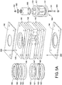
- a first bearing ring pair 121 and a second bearing ring pair 122 are provided to allow proper rotation of the impeller 117.
- the bearing rings advantageously prevent erosion so that flow can be maintained.
- the motor 111 is supported and connected to the base assembly 119 by a pair of posts 125 which are attached to a motor mount platform 129 via bolt assemblies 131.
- a riser tube 132 has a first end disposed in fluid communication with the outlet 133 in the base 119 and is secured at a second end to the motor mount platform 129 via a coupling adaptor 137.
- the shaft, posts and riser tube can be constructed of any high temperature resistant metal, such as stainless steel.
- the base assembly is comprised of steel plates 140, 141, 142, 143 and 144. Of course, it is envisioned that more or fewer than five plates can be used to assemble the base. Three plates is considered to be the most likely minimum number. Interposed between each of the plates is sealing gasket 145, 146, 147 and 148 which can be constructed of Graphoil.
- the plates can be constructed, for example, from 304, 316 and/or 330 stainless steel.
- Silicon carbide bearing rings particularly outer bearings 121 and 122 are seated within recesses in the base and are similarly surrounded by expansion gaskets (which can be constructed of FryeWrap XFP® expanding paper from Unifrax Corporation) 150, 151, 152 and 153, forming an interface between the silicon nitride bonded silicon carbide bearing ring and the adjacent metal surfaces on the outside edge and outer wall.
- expansion gaskets which can be constructed of FryeWrap XFP® expanding paper from Unifrax Corporation
- the expanding gaskets keep bearing rings aligned notwithstanding dissimilar thermal expansion.
- sealing gaskets 154 and 155 seal the inside edge of the bearing rings.
- Shaft 113 is secured to the impeller 117.
- graphite impeller 117 can be machined with a quadralobal extension 160.
- Extension 160 can be shaped in the same manner as the shaft which is described in U.S. Patent 5,634,770 .
- the quadralobal mating allows for dissimilar thermal expansions and high torque transfer.
- a cap member 170 having a cooperatively formed internal surface for receiving the extension 160 is positioned there over.
- Metal cap 170 includes a threaded head end 171 suitable for receiving a cooperatively threaded end of shaft 113.
- the male thread connection allows for field modification to the shaft.
- a bore 180 through impeller 117 is designed to receive a bolt 181 having a threaded end to receive nut 183. Tightening of nut 183 draws impeller 117 and cap 170 into a mated relationship.
- a gasket material 190 (eg. Grafoil®) can be positioned between the interface with shaft 113 and cap 170. Furthermore, a gasket 193 can be provided at the interface between cap 170 and a surface of impeller 117. A graphite plug 191 can be inserted into the bore 180 of the impeller 117 to seal the bolt 181 from exposure to molten metal.
- a gasket material 190 eg. Grafoil®
- a gasket 193 can be provided at the interface between cap 170 and a surface of impeller 117.
- a graphite plug 191 can be inserted into the bore 180 of the impeller 117 to seal the bolt 181 from exposure to molten metal.
- Plates 140-144 are equipped with aligned passages 200 designed to receive bolt and nut assemblies 201 suitable for simultaneously mating the plates 140-144 together to form base 119 and attaching posts 125 to the base 119.
- Posts 125 can include cross members 210 which include alignment passages 211 (optionally with bearing rings) serving as a guide for shaft 113.
- the pump can generally be approximately at least 3 meters long and maintain its functional stability because of the steel superstructure.
- Plate 142 can include a plurality of tap holes 220 designed to receive screws 221 suitable for joining riser tube 132 to the base 119 adjacent outlet 133. Hook elements 230 are secured to the motor mount 129 to facilitate the lifting of the pump assembly into the desired location.
- the present pump provides a suitable emergency pump out apparatus. More particularly, because thermal expansion mismatches are minimized via the pump design, no preheating is required. Accordingly, the pump can be immediately disposed within a body of molten metal when required.
- the pump is particularly advantageous because of its steel construction it can be readily disposed within molten aluminum and molten zinc (and other molten metals) whereas a traditional graphite pump requires a super structure above the furnace to keep the pump in place because of its comparatively high buoyancy.
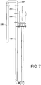
- the pump may be at least 3 meters in length, in which case each of the shaft 113, posts 125 and riser tube 132 will be at least 3 meters in length. Moreover, this length is anticipated to be sufficient to allow the base to be deployed adjacent a lower portion of the molten metal containment vessel, wherein molten metal is lifted via riser tube 132 above the height of a sidewall of the containment vessel. Of course, in certain situations, a taller system may be desired.
- the riser tube may have a length greater than the post/shaft elements.
- base 119 may be disposed on a bottom floor of the vessel being evaluated, it may be exposed to dross and other occlusions. Accordingly, in selected embodiments, it may be advantageous to provide a steel basket 249 (or screen) surrounding the inlet 134. Moreover, the basket 249 can define a plurality of relatively smaller openings 251 that can discourage large dross pieces or inclusions from entering and damaging the pump (see Figure 6 ).
Landscapes
- Engineering & Computer Science (AREA)
- Mechanical Engineering (AREA)
- General Engineering & Computer Science (AREA)
- Structures Of Non-Positive Displacement Pumps (AREA)
Claims (11)
- Pumpe zum Pumpen von geschmolzenem Metall wie zum Beispiel Aluminium, gebildet aus einer Metallbasis (119), die eine Pumpkammer (118) definiert, einem Motoranbau (129), umfassend einen Motor (111), ein Antriebsrad (117), das sich in der Pumpkammer (118) befindet,
mindestens einem Metallpfahl (125), der sich zwischen der Metallbasis (119) und dem Motoranbau (129) erstreckt, einem Metallschaft (113), der sich zwischen dem Motor (111) und dem Antriebsrad (117) erstreckt, mindestens einem Lagerring (121; 122), der das Antriebsrad (117) einschaltet, wobei die Pumpkammer (118) einen Einlass (134) und einen Auslass (133) enthält,
einem Metallsteigrohr (132) in fluider Kommunikation mit dem Auslass,
wobei die Basis aus einer Vielzahl zusammengepasster Stahlplatten (140; 141; 142; 143; 144) gebildet wird,
dadurch gekennzeichnet, dass
die Basis mindestens eine innerste Platte einer größten Dicke, zwei äußerste Platten der dünnsten Dicke und zwei mittlere Platten mittlerer Dicke umfasst und wobei die Pumpkammer (118) durch die innerste Platte definiert wird, wobei der Schaft (113), Pfahl (125) und Steigrohr (132) aus jeglichem Metall mit hoher Temperaturbeständigkeit hergestellt sind. - Pumpe nach Anspruch 1, wobei das Antriebsrad (117) aus einem hochschmelzendem Material besteht.
- Pumpe nach irgendeinem der Ansprüche 1-2, wobei mindestens zwei Platten Aussparungen enthalten, die die Lagerringe aufnehmen.
- Pumpe nach irgendeinem der Ansprüche 1-3, wobei eine dickste der Stahlplatten (140; 141; 142; 143; 144) den Auslass (133) definiert.
- Pumpe nach Anspruch 4, wobei eine Expansionsdichtplatte zwischen einem radialen Rand jedes Lagerrings und einer assoziierten Platte angeordnet ist.
- Pumpe nach irgendeinem der Ansprüche 1-5, wobei eine Dichtplatte (145; 146; 147; 148) zwischen benachbarten Platten angeordnet ist.
- Pumpe nach Anspruch 1, ferner enthaltend eine verschließende Dichtplatte (154; 155), die auf einer horizontalen Innenfläche von jedem Lagerring (121; 122) angeordnet ist.
- Pumpe nach irgendeinem der vorherigen Ansprüche, ferner umfassend ein Verbindungsstück, das den Schaft (113) und das Antriebsrad (117) verbindet, wobei das Verbindungsstück eine Metallschale mit einer Kammer, die dazu ausgelegt ist, einen Abschnitt des Antriebsrades (117) aufzunehmen und einen Überstand, der dazu ausgelegt ist, zu dem Schaft (113) zu passen, umfasst, einen Durchgang, der sich durch eine Wand, die die Schale definiert, und durch den Überstand erstreckt, wobei der Durchgang einen Bolzen (181) derart aufnimmt, dass der Bolzen (181) eine Öffnung in besagtem Antriebsrad (117) passiert und in die Passage durch das Verbindungsstück aufgenommen wird, eine Mutter (183), die auf dem Bolzen (181) bereitgestellt ist, um das Verbindungsstück auf dem Antriebsrad (117) zu sichern.
- Pumpe nach Anspruch 8, wobei besagter Überstand Außengewinde enthält, die dazu ausgelegt sind, ein Ende des Schaftes (113) mit Innengewinde aufzunehmen.
- Verfahren, um im Notfall geschmolzenes Metall aus einem Gefäß zu pumpen, wobei das Verfahren
das Identifizieren eines vorangehenden Zustandes, der ein schnelles Entfernen des geschmolzenen Metalles aus dem Gefäß erfordert, und das anschließende Einführen einer Pumpe nach einem der vorherigen Ansprüche, enthaltend mindestens eine Metallbasis (119), einen Metallpfahl (125), einen Schaft (113), ein Antriebsrad (117), einen Motor (111) und ein Metallsteigrohr (132), in das geschmolzene Metall, das Rotieren der Schaft-(113) und der Antriebsrad(117)kombination mit dem Motor (111), wobei das Antriebsrad (117) innerhalb der Metallbasis (119) angeordnet ist und dazu ausgelegt ist, geschmolzenes Metall in das Steigrohr (132) zu lenken, und das Einführen von Metall aus besagtem Steigrohr (132) in ein zweites Gefäß umfasst. - Verfahren nach Anspruch 10, wobei die Pumpentemperatur der Pumpe unter 100°C ist, wenn diese in das geschmolzene Metall eingeführt wird.
Applications Claiming Priority (1)
| Application Number | Priority Date | Filing Date | Title |
|---|---|---|---|
| US201361832376P | 2013-06-07 | 2013-06-07 |
Publications (2)
| Publication Number | Publication Date |
|---|---|
| EP2811166A1 EP2811166A1 (de) | 2014-12-10 |
| EP2811166B1 true EP2811166B1 (de) | 2018-08-15 |
Family
ID=51178646
Family Applications (1)
| Application Number | Title | Priority Date | Filing Date |
|---|---|---|---|
| EP14171529.2A Active EP2811166B1 (de) | 2013-06-07 | 2014-06-06 | Metalschmelzpumpe und Notfallabpumpen von Metallschmelze |
Country Status (3)
| Country | Link |
|---|---|
| US (2) | US20140363309A1 (de) |
| EP (1) | EP2811166B1 (de) |
| AU (1) | AU2014203104B2 (de) |
Families Citing this family (30)
| Publication number | Priority date | Publication date | Assignee | Title |
|---|---|---|---|---|
| US20070253807A1 (en) | 2006-04-28 | 2007-11-01 | Cooper Paul V | Gas-transfer foot |
| US9410744B2 (en) | 2010-05-12 | 2016-08-09 | Molten Metal Equipment Innovations, Llc | Vessel transfer insert and system |
| US8366993B2 (en) | 2007-06-21 | 2013-02-05 | Cooper Paul V | System and method for degassing molten metal |
| US8337746B2 (en) | 2007-06-21 | 2012-12-25 | Cooper Paul V | Transferring molten metal from one structure to another |
| US9205490B2 (en) | 2007-06-21 | 2015-12-08 | Molten Metal Equipment Innovations, Llc | Transfer well system and method for making same |
| US9409232B2 (en) | 2007-06-21 | 2016-08-09 | Molten Metal Equipment Innovations, Llc | Molten metal transfer vessel and method of construction |
| US9156087B2 (en) | 2007-06-21 | 2015-10-13 | Molten Metal Equipment Innovations, Llc | Molten metal transfer system and rotor |
| US9643247B2 (en) | 2007-06-21 | 2017-05-09 | Molten Metal Equipment Innovations, Llc | Molten metal transfer and degassing system |
| US10428821B2 (en) | 2009-08-07 | 2019-10-01 | Molten Metal Equipment Innovations, Llc | Quick submergence molten metal pump |
| US8524146B2 (en) | 2009-08-07 | 2013-09-03 | Paul V. Cooper | Rotary degassers and components therefor |
| US8444911B2 (en) | 2009-08-07 | 2013-05-21 | Paul V. Cooper | Shaft and post tensioning device |
| US8535603B2 (en) | 2009-08-07 | 2013-09-17 | Paul V. Cooper | Rotary degasser and rotor therefor |
| US9108244B2 (en) | 2009-09-09 | 2015-08-18 | Paul V. Cooper | Immersion heater for molten metal |
| US9903383B2 (en) | 2013-03-13 | 2018-02-27 | Molten Metal Equipment Innovations, Llc | Molten metal rotor with hardened top |
| US9011761B2 (en) | 2013-03-14 | 2015-04-21 | Paul V. Cooper | Ladle with transfer conduit |
| US10052688B2 (en) | 2013-03-15 | 2018-08-21 | Molten Metal Equipment Innovations, Llc | Transfer pump launder system |
| US9551091B2 (en) * | 2013-12-26 | 2017-01-24 | Hexa Nano Carbon LLC | Process and equipment for the production of micro-carbonfibers |
| US10138892B2 (en) | 2014-07-02 | 2018-11-27 | Molten Metal Equipment Innovations, Llc | Rotor and rotor shaft for molten metal |
| US10947980B2 (en) | 2015-02-02 | 2021-03-16 | Molten Metal Equipment Innovations, Llc | Molten metal rotor with hardened blade tips |
| US20170175772A1 (en) * | 2015-12-21 | 2017-06-22 | Karl E. Greer | Post Mounting Assembly and Method for Molten Metal Pump |
| US10267314B2 (en) | 2016-01-13 | 2019-04-23 | Molten Metal Equipment Innovations, Llc | Tensioned support shaft and other molten metal devices |
| EP3655658B1 (de) * | 2017-07-20 | 2022-03-23 | Pyrotek, Inc. | Formpumpenkopplungsvorrichtung und ein verfahren zum füllen einer form |
| US11149747B2 (en) | 2017-11-17 | 2021-10-19 | Molten Metal Equipment Innovations, Llc | Tensioned support post and other molten metal devices |
| CN108240328A (zh) * | 2017-12-29 | 2018-07-03 | 菲格瑞特(苏州)汽车科技有限公司 | 一种用于抽取铝合金与锌合金熔液的泵及其制造方法 |
| CN108916058A (zh) * | 2018-07-18 | 2018-11-30 | 马鞍山马钢表面工程技术有限公司 | 一种快换锌液泵排渣装置 |
| CN109973395B (zh) * | 2019-04-11 | 2021-02-02 | 江苏江大流体技术有限公司 | 一种超高温金属溶液输送泵 |
| US11858036B2 (en) | 2019-05-17 | 2024-01-02 | Molten Metal Equipment Innovations, Llc | System and method to feed mold with molten metal |
| US11873845B2 (en) | 2021-05-28 | 2024-01-16 | Molten Metal Equipment Innovations, Llc | Molten metal transfer device |
| US12146508B2 (en) | 2022-05-26 | 2024-11-19 | Molten Metal Equipment Innovations, Llc | Axial pump and riser |
| WO2025029624A1 (en) * | 2023-07-28 | 2025-02-06 | Pyrotek, Inc. | Post-less molten metal pump |
Family Cites Families (24)
| Publication number | Priority date | Publication date | Assignee | Title |
|---|---|---|---|---|
| US3776660A (en) * | 1972-02-22 | 1973-12-04 | Nl Industries Inc | Pump for molten salts and metals |
| US5181828A (en) * | 1991-11-22 | 1993-01-26 | The Carborundum Company | Molten metal pump |
| US5634770A (en) | 1992-06-12 | 1997-06-03 | Metaullics Systems Co., L.P. | Molten metal pump with vaned impeller |
| AU716224B2 (en) * | 1996-08-07 | 2000-02-24 | Metaullics Systems Co., L.P. | Molten metal transfer pump |
| US5944496A (en) * | 1996-12-03 | 1999-08-31 | Cooper; Paul V. | Molten metal pump with a flexible coupling and cement-free metal-transfer conduit connection |
| JP4493853B2 (ja) * | 1998-11-09 | 2010-06-30 | メトウリクス システムズ カンパニー,エル.ピー. | 溶融金属ポンピング装置用のシャフトとポストのアセンブリ |
| US6887425B2 (en) * | 1998-11-09 | 2005-05-03 | Metaullics Systems Co., L.P. | Shaft and post assemblies for molten metal apparatus |
| US6152691A (en) * | 1999-02-04 | 2000-11-28 | Thut; Bruno H. | Pumps for pumping molten metal |
| US6187096B1 (en) * | 1999-03-02 | 2001-02-13 | Bruno H. Thut | Spray assembly for molten metal |
| US6439860B1 (en) * | 1999-11-22 | 2002-08-27 | Karl Greer | Chambered vane impeller molten metal pump |
| CA2333808C (en) * | 2000-02-01 | 2011-01-04 | Metaullics Systems Co., L.P. | Pump for molten materials with suspended solids |
| US6375422B1 (en) * | 2000-07-28 | 2002-04-23 | Bechtel Bwxt Idaho, Llc | Apparatus for pumping liquids at or below the boiling point |
| US6533535B2 (en) * | 2001-04-06 | 2003-03-18 | Bruno H. Thut | Molten metal pump with protected inlet |
| US6918741B2 (en) * | 2002-11-15 | 2005-07-19 | Pyrotek, Inc. | Molten metal pump impeller system |
| DE102004009546B4 (de) * | 2004-02-24 | 2007-05-16 | Strikowestofen Gmbh | Pumpvorrichtung für einen Schmelzeofen |
| CA3051752C (en) * | 2004-07-07 | 2021-12-14 | Pyrotek Inc. | Molten metal pump |
| US7425092B1 (en) * | 2005-01-18 | 2008-09-16 | Impulse Devices, Inc. | Hydraulic actuated cavitation chamber with integrated fluid rotation system |
| US10428821B2 (en) * | 2009-08-07 | 2019-10-01 | Molten Metal Equipment Innovations, Llc | Quick submergence molten metal pump |
| US8714914B2 (en) * | 2009-09-08 | 2014-05-06 | Paul V. Cooper | Molten metal pump filter |
| WO2011134040A1 (en) * | 2010-04-30 | 2011-11-03 | Shunderson Communications, Inc. | A motor driven rotational sampling apparatus with removable cutting tools for material collection |
| AU2012245552B2 (en) * | 2011-04-18 | 2017-06-08 | Pyrotek, Inc. | Mold pump assembly |
| US8647058B2 (en) * | 2011-06-27 | 2014-02-11 | Bruno H. Thut | Cementless pump for pumping molten metal |
| CA2865426C (en) * | 2012-02-27 | 2020-07-28 | Deec, Inc. | Oxygen-rich plasma generators for boosting internal combustion engines |
| US10052688B2 (en) * | 2013-03-15 | 2018-08-21 | Molten Metal Equipment Innovations, Llc | Transfer pump launder system |
-
2014
- 2014-06-03 US US14/294,858 patent/US20140363309A1/en not_active Abandoned
- 2014-06-06 EP EP14171529.2A patent/EP2811166B1/de active Active
- 2014-06-06 AU AU2014203104A patent/AU2014203104B2/en active Active
-
2021
- 2021-01-25 US US17/157,625 patent/US20210148374A1/en active Pending
Non-Patent Citations (1)
| Title |
|---|
| None * |
Also Published As
| Publication number | Publication date |
|---|---|
| US20210148374A1 (en) | 2021-05-20 |
| EP2811166A1 (de) | 2014-12-10 |
| US20140363309A1 (en) | 2014-12-11 |
| AU2014203104B2 (en) | 2018-07-19 |
| AU2014203104A1 (en) | 2015-01-15 |
Similar Documents
| Publication | Publication Date | Title |
|---|---|---|
| US20210148374A1 (en) | Emergency molten metal pump out | |
| US3849587A (en) | Cooling devices for protecting refractory linings of furnaces | |
| US10428821B2 (en) | Quick submergence molten metal pump | |
| US20110303706A1 (en) | Launder transfer insert and system | |
| CN104981672B (zh) | 感应炉和用于处理待存储的金属废料的方法 | |
| CN104654783B (zh) | 一种上部浸入式加热熔化保温炉 | |
| US20020089099A1 (en) | Molten metal holding furnace baffle/heater system | |
| US20160265849A1 (en) | Furnace with refractory bricks that define cooling channels for gaseous media | |
| EP3574273B1 (de) | Oberes ladedach für lichtbogen, metallurgische oder raffinieröfen und system dafür | |
| PL199946B1 (pl) | Element chłodzący i sposób jego montażu | |
| RU2281974C2 (ru) | Охлаждающий элемент для охлаждения металлургической печи | |
| US20250347281A1 (en) | Battery operated molten metal pump | |
| Beall et al. | Production of Titanium Castings | |
| KR102382705B1 (ko) | 야금 반응기의 충전 설비 | |
| Mc Dougall | Water-cooled tap-hole blocks | |
| US6174492B1 (en) | Forebay for am Metallurgical furnace | |
| RU208227U1 (ru) | Газосборный колокол алюминиевого электролизера | |
| CN111373218A (zh) | 耐磨、单个穿透处的冷却壁冷却器 | |
| CN115679132B (zh) | 一种铜钢组合的真空冷却罐及其制造方法 | |
| Dötsch et al. | Components and design of induction crucible furnaces | |
| CN216347766U (zh) | 电弧熔炼炉 | |
| Kennedy et al. | High intensity slag resistance furnace design | |
| MacRae | Designing Smelting Furnaces to Meet Process Requirements | |
| CN102089608A (zh) | 用于对冶金炉(ac、dc)的耐火内衬进行冷却的冷却元件 | |
| Mc Dougall et al. | PGM Furnace Design, Construction, Improvement, and Performance Optimisation |
Legal Events
| Date | Code | Title | Description |
|---|---|---|---|
| PUAI | Public reference made under article 153(3) epc to a published international application that has entered the european phase |
Free format text: ORIGINAL CODE: 0009012 |
|
| 17P | Request for examination filed |
Effective date: 20140606 |
|
| AK | Designated contracting states |
Kind code of ref document: A1 Designated state(s): AL AT BE BG CH CY CZ DE DK EE ES FI FR GB GR HR HU IE IS IT LI LT LU LV MC MK MT NL NO PL PT RO RS SE SI SK SM TR |
|
| AX | Request for extension of the european patent |
Extension state: BA ME |
|
| RIN1 | Information on inventor provided before grant (corrected) |
Inventor name: HENDERSON, RICHARD S. Inventor name: TIPTON, JON Inventor name: BOSWORTH, PAUL Inventor name: JETTEN, PETER CORNELIS Inventor name: HORSFALL, ANDREW |
|
| R17P | Request for examination filed (corrected) |
Effective date: 20150610 |
|
| RBV | Designated contracting states (corrected) |
Designated state(s): AL AT BE BG CH CY CZ DE DK EE ES FI FR GB GR HR HU IE IS IT LI LT LU LV MC MK MT NL NO PL PT RO RS SE SI SK SM TR |
|
| 17Q | First examination report despatched |
Effective date: 20151109 |
|
| STAA | Information on the status of an ep patent application or granted ep patent |
Free format text: STATUS: EXAMINATION IS IN PROGRESS |
|
| RIC1 | Information provided on ipc code assigned before grant |
Ipc: F04D 29/046 20060101ALI20180209BHEP Ipc: F04D 29/42 20060101ALI20180209BHEP Ipc: F04D 7/06 20060101AFI20180209BHEP Ipc: F04D 29/18 20060101ALI20180209BHEP |
|
| GRAP | Despatch of communication of intention to grant a patent |
Free format text: ORIGINAL CODE: EPIDOSNIGR1 |
|
| STAA | Information on the status of an ep patent application or granted ep patent |
Free format text: STATUS: GRANT OF PATENT IS INTENDED |
|
| INTG | Intention to grant announced |
Effective date: 20180319 |
|
| GRAS | Grant fee paid |
Free format text: ORIGINAL CODE: EPIDOSNIGR3 |
|
| GRAA | (expected) grant |
Free format text: ORIGINAL CODE: 0009210 |
|
| STAA | Information on the status of an ep patent application or granted ep patent |
Free format text: STATUS: THE PATENT HAS BEEN GRANTED |
|
| AK | Designated contracting states |
Kind code of ref document: B1 Designated state(s): AL AT BE BG CH CY CZ DE DK EE ES FI FR GB GR HR HU IE IS IT LI LT LU LV MC MK MT NL NO PL PT RO RS SE SI SK SM TR |
|
| REG | Reference to a national code |
Ref country code: CH Ref legal event code: EP Ref country code: GB Ref legal event code: FG4D Ref country code: AT Ref legal event code: REF Ref document number: 1030110 Country of ref document: AT Kind code of ref document: T Effective date: 20180815 |
|
| REG | Reference to a national code |
Ref country code: IE Ref legal event code: FG4D |
|
| REG | Reference to a national code |
Ref country code: DE Ref legal event code: R096 Ref document number: 602014030323 Country of ref document: DE |
|
| REG | Reference to a national code |
Ref country code: NL Ref legal event code: MP Effective date: 20180815 |
|
| REG | Reference to a national code |
Ref country code: LT Ref legal event code: MG4D |
|
| REG | Reference to a national code |
Ref country code: AT Ref legal event code: MK05 Ref document number: 1030110 Country of ref document: AT Kind code of ref document: T Effective date: 20180815 |
|
| PG25 | Lapsed in a contracting state [announced via postgrant information from national office to epo] |
Ref country code: GR Free format text: LAPSE BECAUSE OF FAILURE TO SUBMIT A TRANSLATION OF THE DESCRIPTION OR TO PAY THE FEE WITHIN THE PRESCRIBED TIME-LIMIT Effective date: 20181116 Ref country code: BG Free format text: LAPSE BECAUSE OF FAILURE TO SUBMIT A TRANSLATION OF THE DESCRIPTION OR TO PAY THE FEE WITHIN THE PRESCRIBED TIME-LIMIT Effective date: 20181115 Ref country code: AT Free format text: LAPSE BECAUSE OF FAILURE TO SUBMIT A TRANSLATION OF THE DESCRIPTION OR TO PAY THE FEE WITHIN THE PRESCRIBED TIME-LIMIT Effective date: 20180815 Ref country code: NL Free format text: LAPSE BECAUSE OF FAILURE TO SUBMIT A TRANSLATION OF THE DESCRIPTION OR TO PAY THE FEE WITHIN THE PRESCRIBED TIME-LIMIT Effective date: 20180815 Ref country code: NO Free format text: LAPSE BECAUSE OF FAILURE TO SUBMIT A TRANSLATION OF THE DESCRIPTION OR TO PAY THE FEE WITHIN THE PRESCRIBED TIME-LIMIT Effective date: 20181115 Ref country code: IS Free format text: LAPSE BECAUSE OF FAILURE TO SUBMIT A TRANSLATION OF THE DESCRIPTION OR TO PAY THE FEE WITHIN THE PRESCRIBED TIME-LIMIT Effective date: 20181215 Ref country code: FI Free format text: LAPSE BECAUSE OF FAILURE TO SUBMIT A TRANSLATION OF THE DESCRIPTION OR TO PAY THE FEE WITHIN THE PRESCRIBED TIME-LIMIT Effective date: 20180815 Ref country code: RS Free format text: LAPSE BECAUSE OF FAILURE TO SUBMIT A TRANSLATION OF THE DESCRIPTION OR TO PAY THE FEE WITHIN THE PRESCRIBED TIME-LIMIT Effective date: 20180815 Ref country code: LT Free format text: LAPSE BECAUSE OF FAILURE TO SUBMIT A TRANSLATION OF THE DESCRIPTION OR TO PAY THE FEE WITHIN THE PRESCRIBED TIME-LIMIT Effective date: 20180815 Ref country code: SE Free format text: LAPSE BECAUSE OF FAILURE TO SUBMIT A TRANSLATION OF THE DESCRIPTION OR TO PAY THE FEE WITHIN THE PRESCRIBED TIME-LIMIT Effective date: 20180815 |
|
| PG25 | Lapsed in a contracting state [announced via postgrant information from national office to epo] |
Ref country code: AL Free format text: LAPSE BECAUSE OF FAILURE TO SUBMIT A TRANSLATION OF THE DESCRIPTION OR TO PAY THE FEE WITHIN THE PRESCRIBED TIME-LIMIT Effective date: 20180815 Ref country code: HR Free format text: LAPSE BECAUSE OF FAILURE TO SUBMIT A TRANSLATION OF THE DESCRIPTION OR TO PAY THE FEE WITHIN THE PRESCRIBED TIME-LIMIT Effective date: 20180815 Ref country code: LV Free format text: LAPSE BECAUSE OF FAILURE TO SUBMIT A TRANSLATION OF THE DESCRIPTION OR TO PAY THE FEE WITHIN THE PRESCRIBED TIME-LIMIT Effective date: 20180815 |
|
| PG25 | Lapsed in a contracting state [announced via postgrant information from national office to epo] |
Ref country code: PL Free format text: LAPSE BECAUSE OF FAILURE TO SUBMIT A TRANSLATION OF THE DESCRIPTION OR TO PAY THE FEE WITHIN THE PRESCRIBED TIME-LIMIT Effective date: 20180815 Ref country code: EE Free format text: LAPSE BECAUSE OF FAILURE TO SUBMIT A TRANSLATION OF THE DESCRIPTION OR TO PAY THE FEE WITHIN THE PRESCRIBED TIME-LIMIT Effective date: 20180815 Ref country code: CZ Free format text: LAPSE BECAUSE OF FAILURE TO SUBMIT A TRANSLATION OF THE DESCRIPTION OR TO PAY THE FEE WITHIN THE PRESCRIBED TIME-LIMIT Effective date: 20180815 Ref country code: IT Free format text: LAPSE BECAUSE OF FAILURE TO SUBMIT A TRANSLATION OF THE DESCRIPTION OR TO PAY THE FEE WITHIN THE PRESCRIBED TIME-LIMIT Effective date: 20180815 Ref country code: ES Free format text: LAPSE BECAUSE OF FAILURE TO SUBMIT A TRANSLATION OF THE DESCRIPTION OR TO PAY THE FEE WITHIN THE PRESCRIBED TIME-LIMIT Effective date: 20180815 Ref country code: RO Free format text: LAPSE BECAUSE OF FAILURE TO SUBMIT A TRANSLATION OF THE DESCRIPTION OR TO PAY THE FEE WITHIN THE PRESCRIBED TIME-LIMIT Effective date: 20180815 |
|
| REG | Reference to a national code |
Ref country code: DE Ref legal event code: R097 Ref document number: 602014030323 Country of ref document: DE |
|
| PG25 | Lapsed in a contracting state [announced via postgrant information from national office to epo] |
Ref country code: SM Free format text: LAPSE BECAUSE OF FAILURE TO SUBMIT A TRANSLATION OF THE DESCRIPTION OR TO PAY THE FEE WITHIN THE PRESCRIBED TIME-LIMIT Effective date: 20180815 Ref country code: DK Free format text: LAPSE BECAUSE OF FAILURE TO SUBMIT A TRANSLATION OF THE DESCRIPTION OR TO PAY THE FEE WITHIN THE PRESCRIBED TIME-LIMIT Effective date: 20180815 Ref country code: SK Free format text: LAPSE BECAUSE OF FAILURE TO SUBMIT A TRANSLATION OF THE DESCRIPTION OR TO PAY THE FEE WITHIN THE PRESCRIBED TIME-LIMIT Effective date: 20180815 |
|
| PLBE | No opposition filed within time limit |
Free format text: ORIGINAL CODE: 0009261 |
|
| STAA | Information on the status of an ep patent application or granted ep patent |
Free format text: STATUS: NO OPPOSITION FILED WITHIN TIME LIMIT |
|
| 26N | No opposition filed |
Effective date: 20190516 |
|
| PG25 | Lapsed in a contracting state [announced via postgrant information from national office to epo] |
Ref country code: SI Free format text: LAPSE BECAUSE OF FAILURE TO SUBMIT A TRANSLATION OF THE DESCRIPTION OR TO PAY THE FEE WITHIN THE PRESCRIBED TIME-LIMIT Effective date: 20180815 |
|
| PG25 | Lapsed in a contracting state [announced via postgrant information from national office to epo] |
Ref country code: MC Free format text: LAPSE BECAUSE OF FAILURE TO SUBMIT A TRANSLATION OF THE DESCRIPTION OR TO PAY THE FEE WITHIN THE PRESCRIBED TIME-LIMIT Effective date: 20180815 |
|
| REG | Reference to a national code |
Ref country code: CH Ref legal event code: PL |
|
| REG | Reference to a national code |
Ref country code: BE Ref legal event code: MM Effective date: 20190630 |
|
| PG25 | Lapsed in a contracting state [announced via postgrant information from national office to epo] |
Ref country code: TR Free format text: LAPSE BECAUSE OF FAILURE TO SUBMIT A TRANSLATION OF THE DESCRIPTION OR TO PAY THE FEE WITHIN THE PRESCRIBED TIME-LIMIT Effective date: 20180815 |
|
| PG25 | Lapsed in a contracting state [announced via postgrant information from national office to epo] |
Ref country code: IE Free format text: LAPSE BECAUSE OF NON-PAYMENT OF DUE FEES Effective date: 20190606 |
|
| PG25 | Lapsed in a contracting state [announced via postgrant information from national office to epo] |
Ref country code: LI Free format text: LAPSE BECAUSE OF NON-PAYMENT OF DUE FEES Effective date: 20190630 Ref country code: CH Free format text: LAPSE BECAUSE OF NON-PAYMENT OF DUE FEES Effective date: 20190630 Ref country code: LU Free format text: LAPSE BECAUSE OF NON-PAYMENT OF DUE FEES Effective date: 20190606 Ref country code: BE Free format text: LAPSE BECAUSE OF NON-PAYMENT OF DUE FEES Effective date: 20190630 |
|
| PG25 | Lapsed in a contracting state [announced via postgrant information from national office to epo] |
Ref country code: FR Free format text: LAPSE BECAUSE OF NON-PAYMENT OF DUE FEES Effective date: 20190630 Ref country code: PT Free format text: LAPSE BECAUSE OF FAILURE TO SUBMIT A TRANSLATION OF THE DESCRIPTION OR TO PAY THE FEE WITHIN THE PRESCRIBED TIME-LIMIT Effective date: 20181215 |
|
| PG25 | Lapsed in a contracting state [announced via postgrant information from national office to epo] |
Ref country code: CY Free format text: LAPSE BECAUSE OF FAILURE TO SUBMIT A TRANSLATION OF THE DESCRIPTION OR TO PAY THE FEE WITHIN THE PRESCRIBED TIME-LIMIT Effective date: 20180815 |
|
| PG25 | Lapsed in a contracting state [announced via postgrant information from national office to epo] |
Ref country code: MT Free format text: LAPSE BECAUSE OF FAILURE TO SUBMIT A TRANSLATION OF THE DESCRIPTION OR TO PAY THE FEE WITHIN THE PRESCRIBED TIME-LIMIT Effective date: 20180815 Ref country code: HU Free format text: LAPSE BECAUSE OF FAILURE TO SUBMIT A TRANSLATION OF THE DESCRIPTION OR TO PAY THE FEE WITHIN THE PRESCRIBED TIME-LIMIT; INVALID AB INITIO Effective date: 20140606 |
|
| PG25 | Lapsed in a contracting state [announced via postgrant information from national office to epo] |
Ref country code: MK Free format text: LAPSE BECAUSE OF FAILURE TO SUBMIT A TRANSLATION OF THE DESCRIPTION OR TO PAY THE FEE WITHIN THE PRESCRIBED TIME-LIMIT Effective date: 20180815 |
|
| PGFP | Annual fee paid to national office [announced via postgrant information from national office to epo] |
Ref country code: DE Payment date: 20250509 Year of fee payment: 12 |
|
| PGFP | Annual fee paid to national office [announced via postgrant information from national office to epo] |
Ref country code: GB Payment date: 20250508 Year of fee payment: 12 |