EP2811115A1 - Profil d'aube pour turbine à gaz, pale et aube de guidage - Google Patents
Profil d'aube pour turbine à gaz, pale et aube de guidage Download PDFInfo
- Publication number
- EP2811115A1 EP2811115A1 EP13170564.2A EP13170564A EP2811115A1 EP 2811115 A1 EP2811115 A1 EP 2811115A1 EP 13170564 A EP13170564 A EP 13170564A EP 2811115 A1 EP2811115 A1 EP 2811115A1
- Authority
- EP
- European Patent Office
- Prior art keywords
- arc
- airfoil
- platform
- blade
- vane
- Prior art date
- Legal status (The legal status is an assumption and is not a legal conclusion. Google has not performed a legal analysis and makes no representation as to the accuracy of the status listed.)
- Withdrawn
Links
Images


Classifications
-
- F—MECHANICAL ENGINEERING; LIGHTING; HEATING; WEAPONS; BLASTING
- F01—MACHINES OR ENGINES IN GENERAL; ENGINE PLANTS IN GENERAL; STEAM ENGINES
- F01D—NON-POSITIVE DISPLACEMENT MACHINES OR ENGINES, e.g. STEAM TURBINES
- F01D5/00—Blades; Blade-carrying members; Heating, heat-insulating, cooling or antivibration means on the blades or the members
- F01D5/12—Blades
- F01D5/14—Form or construction
- F01D5/141—Shape, i.e. outer, aerodynamic form
- F01D5/142—Shape, i.e. outer, aerodynamic form of the blades of successive rotor or stator blade-rows
- F01D5/143—Contour of the outer or inner working fluid flow path wall, i.e. shroud or hub contour
-
- F—MECHANICAL ENGINEERING; LIGHTING; HEATING; WEAPONS; BLASTING
- F01—MACHINES OR ENGINES IN GENERAL; ENGINE PLANTS IN GENERAL; STEAM ENGINES
- F01D—NON-POSITIVE DISPLACEMENT MACHINES OR ENGINES, e.g. STEAM TURBINES
- F01D5/00—Blades; Blade-carrying members; Heating, heat-insulating, cooling or antivibration means on the blades or the members
- F01D5/12—Blades
- F01D5/14—Form or construction
- F01D5/141—Shape, i.e. outer, aerodynamic form
- F01D5/145—Means for influencing boundary layers or secondary circulations
Definitions
- the present invention relates to an airfoil for a gas turbine, in particular, to a compound fillet between an airfoil and a platform.
- the present invention also relates to a blade and a vane for a gas turbine.
- a gas turbine typically includes at least one rotor assembly in which a plurality of blades/vanes, comprising airfoils radially extending from platforms, are circumferentially fitted and distributed around a rotor disk.
- centrifugal forces generate circumferential rim stress in the rotating blades.
- gas pressure and vibration may also generate stress.
- These stresses can concentrate at the transition between the platform and the airfoil. This stress concentration can be minimized by fillets at the platform/airfoil connection portion. Adequate stress relief can however only be achieved with an adequately sized and shaped fillet.
- a compound fillet for a turbine blade is disclosed in EP2184442A1 , which covers an airfoil to platform join and is configured to comprise a first arc and a second arc.
- the first arc has a first end tangential to the airfoil surface.
- the second arc having a first end tangentially adjoins the second end of the first arc and a second end adjoins the plat form surface.
- the radius of the first arc is larger than the radius of the second arc.
- another compound fillet also is disclosed in this reference, which comprises a first arc and a second arc wherein the second arc adjoins non-tangentially the platform surface.
- a kind of transition between a surface of a blade/vane airfoil and a platform at an end of the airfoil is disclosed in GB2353826A , which comprises at least two curves of different radii, the radius of the curve nearest the surface of the airfoil being larger than the radius of the curve nearest to the platform.
- the transition may comprise two curves of different radii separated by a straight line section, or it may form a section of an ellipse.
- a cooled moving blade for a gas turbine is disclosed in US6190128B1 , which has a base portion of a profile formed by an elliptically curved surface and a rectilinear surface portion, wherein the rectilinear surface portion is provided at a hub portion of the blade where thermal stress is large.
- It is an object of the present invention is to provide an airfoil for a blade and/or a vane, which could optimize the structure for stress relief, in order to prolong the working lives thereof.
- an airfoil for a gas turbine which comprises a compound fillet disposed between the airfoil and a platform, wherein the compound fillet consists of a first arc and a second arc, a first end of the first arc tangentially adjoining an outer surface of the airfoil, a second end of the first arc tangentially adjoining a first end of the second arc, and a second end of the second arc tangentially adjoining a surface of the platform, wherein the following equation is satisfied: 0.15 ⁇ R ⁇ 1 / s ⁇ 0.45 , and 0.09 ⁇ a / s ⁇ 0.27 , where R1 represents the radius of the first arc, s represent the chord length of the airfoil, and a represents the distance between the point where the first end of the first arc adjoins the outer surface of the airfoil and the top surface of the platform in the direction along the extension of the outer surface of the airf
- the following equation is further satisfied: 0.024 ⁇ R ⁇ 2 / s ⁇ 0.072 where R2 represents the radius of the second arc.
- a blade for a gas turbine which comprises the airfoil according to the present invention.
- a vane for a gas turbine which comprises the airfoil according to the present invention.
- the structure of the airfoil, the blade comprising the same and/or the vane comprising the same are improved in stress relief capacity, and prevented from pre-mature cracks during operation of the blade and/or vane.
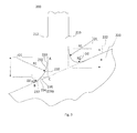
- Figure 1 shows a schematic cut-away view of an airfoil 110 for a blade 100 of a gas turbine according to example embodiments of the present invention.
- the blade 100 comprises the airfoil 110 with an outer surface 112, and a platform 120 with a top surface 122.
- a compound fillet 130 is disposed between the airfoil 110 and the platform 120.
- the profile of the blade 100 represents a symmetrical structure.
- one side of the airfoil 110 is numerated and described for purpose of simplicity and clarity.
- the compound fillet 130 comprises a first arc 132 with a radius R1 and a center 01, and a second arc 134 with a radius R2 and a center 02, where the first arc 132 tangentially adjoins at its first end 133 the outer surface 112 of the airfoil 110 at the point A, and the second arc 134 tangentially adjoins at its second end 137 the top surface 122 of the platform 120 at the point B, and the second end 135 of the first arc 132 and the first end 136 of the second arc 134 tangentially adjoin with each other. As shown in Fig.
- a length a indicates the distance between the point A and the platform 120 in the direction of the extension of the outer surface 112 of the airfoil, i.e. a represents the distance between the point A where the first end 133 of the first arc 132 adjoins the outer surface 112 of the airfoil 110 and the top surface 122 of the platform 120 in the direction along the extension of the outer surface 112 of the airfoil 110.
- Fig.1 it is shown the extension of the outer surface 112 of the airfoil 110, represented by broken line, and the extension of the top surface 122 of the platform 120, represented also by broken line, intersect at point C.
- the length a represents the length AC.
- Fig.2 shows the section view of the airfoil 110 of the blade 100 or vane 200(shown in Fig.3 ), where s represents a chord of the blade 100 or vane 200.
- chord refers to the length of the perpendicular projection of the blade/vane profile onto the chord line, where the chord line refers to, if a two dimensional blade/vane section were laid convex side up on a flat surface, the line between the points where the front and rear of the blade/vane section would touch the surface.
- the airfoil 110 is structured to satisfy the following equation: 0.15 ⁇ R ⁇ 1 / s ⁇ 0.45 , 0.09 ⁇ a / s ⁇ 0.27.
- the airfoil is further structured to satisfy the following equation: 0.024 ⁇ R ⁇ 2 / s ⁇ 0.072.
- the airfoil 110 may provide a blade that optimizes stress relief capacity as the blade is operated with high speed under high temperature and pressure. Thus, the working life of the blade is substantially prolonged.
- Fig. 3 shows a schematic cut-away view of an airfoil 210 for a vane 200 of a gas turbine according to example embodiments of the present invention.
- the vane 200 comprises an airfoil 210 with an outer surface 212, and a platform 220 with a top surface 222.
- a compound fillet 230 is disposed between the airfoil 210 and the platform 220.
- the compound fillet 230 comprises a first arc 232 with a radius R1 and a center 01, and a second arc 234 with a radius R2 and a center 02, where the first arc 232 tangentially adjoins at its first end 233 the outer surface 212 of the airfoil 210 at the point A, and the second arc 234 tangentially adjoins at its second end 237 the top surface 222 of the platform 220 at the point B, and the second end 235 of the first arc 232 and the first end 236 of the second arc 234 tangentially adjoin with each other. As shown in Fig.
- a length a indicates the distance between the point A and the platform 220 in the direction of the extension of the outer surface 212 of the airfoil, i.e. a represents the distance between the point A where the first end 233 of the first arc 232 adjoins the outer surface 212 of the airfoil 210 and the top surface 222 of the platform 220 in the direction along the extension of the outer surface 212 of the airfoil 210.
- Fig.3 it is shown the extension of the outer surface 212 of the airfoil, represented by broken line, and the extension of the top surface 222 of the platform 220, represented also by broken line, intersect at point C.
- the length a represents the length AC.
- the axis of the vane 200 is generally angled with respect the platform by certain angles.
- the compound fillets 230 on the left and right side of the airfoil 210 differ in shape from each other.
- it is designed that R1, R2, a and s are adopted on both sides, except that the positions of 01 and 02 are different.
- the present invention may extensively apply to both blades and vanes of a gas turbine.
- the general concept of the present invention intends to cover both blade and vane utilized in a gas turbine.
- the objective is to optimize the structure of the blade and/or the vane, in order to prolong their working life and preventing pre-mature cracking due to stress generated by high speed rotation, high temperature and/or high pressure.
Priority Applications (5)
| Application Number | Priority Date | Filing Date | Title |
|---|---|---|---|
| EP13170564.2A EP2811115A1 (fr) | 2013-06-05 | 2013-06-05 | Profil d'aube pour turbine à gaz, pale et aube de guidage |
| US14/280,927 US9581027B2 (en) | 2013-06-05 | 2014-05-19 | Airfoil for gas turbine, blade and vane |
| KR1020140062820A KR101654530B1 (ko) | 2013-06-05 | 2014-05-26 | 가스 터빈용 에어포일, 블레이드 및 베인 |
| EP14171180.4A EP2811116B1 (fr) | 2013-06-05 | 2014-06-04 | Aube pour turbine à gaz, aube de rotor et stator |
| CN201410246228.9A CN104234754B (zh) | 2013-06-05 | 2014-06-05 | 用于燃气涡轮的翼型件、叶片和导叶 |
Applications Claiming Priority (1)
| Application Number | Priority Date | Filing Date | Title |
|---|---|---|---|
| EP13170564.2A EP2811115A1 (fr) | 2013-06-05 | 2013-06-05 | Profil d'aube pour turbine à gaz, pale et aube de guidage |
Publications (1)
| Publication Number | Publication Date |
|---|---|
| EP2811115A1 true EP2811115A1 (fr) | 2014-12-10 |
Family
ID=48537883
Family Applications (2)
| Application Number | Title | Priority Date | Filing Date |
|---|---|---|---|
| EP13170564.2A Withdrawn EP2811115A1 (fr) | 2013-06-05 | 2013-06-05 | Profil d'aube pour turbine à gaz, pale et aube de guidage |
| EP14171180.4A Active EP2811116B1 (fr) | 2013-06-05 | 2014-06-04 | Aube pour turbine à gaz, aube de rotor et stator |
Family Applications After (1)
| Application Number | Title | Priority Date | Filing Date |
|---|---|---|---|
| EP14171180.4A Active EP2811116B1 (fr) | 2013-06-05 | 2014-06-04 | Aube pour turbine à gaz, aube de rotor et stator |
Country Status (4)
| Country | Link |
|---|---|
| US (1) | US9581027B2 (fr) |
| EP (2) | EP2811115A1 (fr) |
| KR (1) | KR101654530B1 (fr) |
| CN (1) | CN104234754B (fr) |
Families Citing this family (6)
| Publication number | Priority date | Publication date | Assignee | Title |
|---|---|---|---|---|
| US10619492B2 (en) * | 2017-12-11 | 2020-04-14 | United Technologies Corporation | Vane air inlet with fillet |
| US10724390B2 (en) * | 2018-03-16 | 2020-07-28 | General Electric Company | Collar support assembly for airfoils |
| US11098591B1 (en) | 2019-02-04 | 2021-08-24 | Raytheon Technologies Corporation | Turbine blade with contoured fillet |
| JP6776465B1 (ja) * | 2020-01-27 | 2020-10-28 | 三菱パワー株式会社 | タービン動翼 |
| US11578607B2 (en) * | 2020-12-15 | 2023-02-14 | Pratt & Whitney Canada Corp. | Airfoil having a spline fillet |
| KR20230060370A (ko) | 2021-10-27 | 2023-05-04 | 두산에너빌리티 주식회사 | 터빈 베인, 및 이를 포함하는 터빈 |
Citations (7)
| Publication number | Priority date | Publication date | Assignee | Title |
|---|---|---|---|---|
| SU556238A1 (ru) * | 1975-09-23 | 1977-04-30 | Предприятие П/Я А-3513 | Рабочее колесо радиально-осевой гидромашины |
| US6190128B1 (en) | 1997-06-12 | 2001-02-20 | Mitsubishi Heavy Industries, Ltd. | Cooled moving blade for gas turbine |
| GB2353826A (en) | 1999-08-30 | 2001-03-07 | Mtu Muenchen Gmbh | Aerofoil to platform transition in gas turbine blade/vane |
| WO2005116404A1 (fr) * | 2004-05-29 | 2005-12-08 | Mtu Aero Engines Gmbh | Aube comportant une zone de transition |
| EP1731712A1 (fr) * | 2005-06-06 | 2006-12-13 | General Electric Company | Aube de turbine comprenant un contour de raccordement variable et composé |
| EP2184442A1 (fr) | 2008-11-11 | 2010-05-12 | ALSTOM Technology Ltd | Raccord de profil d'aube |
| US20100284815A1 (en) * | 2008-11-19 | 2010-11-11 | Alstom Technologies Ltd. Llc | Compound variable elliptical airfoil fillet |
Family Cites Families (6)
| Publication number | Priority date | Publication date | Assignee | Title |
|---|---|---|---|---|
| US4431376A (en) * | 1980-10-27 | 1984-02-14 | United Technologies Corporation | Airfoil shape for arrays of airfoils |
| US5480285A (en) * | 1993-08-23 | 1996-01-02 | Westinghouse Electric Corporation | Steam turbine blade |
| CN100497890C (zh) | 2007-09-06 | 2009-06-10 | 东方电气集团东方汽轮机有限公司 | 变转速汽轮机末级动叶片 |
| US8287241B2 (en) * | 2008-11-21 | 2012-10-16 | Alstom Technology Ltd | Turbine blade platform trailing edge undercut |
| US9120562B2 (en) * | 2009-05-05 | 2015-09-01 | Aerostar Aircraft Corporation | Aircraft winglet design having a compound curve profile |
| US9045987B2 (en) * | 2012-06-15 | 2015-06-02 | United Technologies Corporation | Cooling for a turbine airfoil trailing edge |
-
2013
- 2013-06-05 EP EP13170564.2A patent/EP2811115A1/fr not_active Withdrawn
-
2014
- 2014-05-19 US US14/280,927 patent/US9581027B2/en not_active Expired - Fee Related
- 2014-05-26 KR KR1020140062820A patent/KR101654530B1/ko active IP Right Grant
- 2014-06-04 EP EP14171180.4A patent/EP2811116B1/fr active Active
- 2014-06-05 CN CN201410246228.9A patent/CN104234754B/zh active Active
Patent Citations (7)
| Publication number | Priority date | Publication date | Assignee | Title |
|---|---|---|---|---|
| SU556238A1 (ru) * | 1975-09-23 | 1977-04-30 | Предприятие П/Я А-3513 | Рабочее колесо радиально-осевой гидромашины |
| US6190128B1 (en) | 1997-06-12 | 2001-02-20 | Mitsubishi Heavy Industries, Ltd. | Cooled moving blade for gas turbine |
| GB2353826A (en) | 1999-08-30 | 2001-03-07 | Mtu Muenchen Gmbh | Aerofoil to platform transition in gas turbine blade/vane |
| WO2005116404A1 (fr) * | 2004-05-29 | 2005-12-08 | Mtu Aero Engines Gmbh | Aube comportant une zone de transition |
| EP1731712A1 (fr) * | 2005-06-06 | 2006-12-13 | General Electric Company | Aube de turbine comprenant un contour de raccordement variable et composé |
| EP2184442A1 (fr) | 2008-11-11 | 2010-05-12 | ALSTOM Technology Ltd | Raccord de profil d'aube |
| US20100284815A1 (en) * | 2008-11-19 | 2010-11-11 | Alstom Technologies Ltd. Llc | Compound variable elliptical airfoil fillet |
Also Published As
| Publication number | Publication date |
|---|---|
| US20140363302A1 (en) | 2014-12-11 |
| US9581027B2 (en) | 2017-02-28 |
| EP2811116B1 (fr) | 2019-04-24 |
| KR101654530B1 (ko) | 2016-09-06 |
| CN104234754A (zh) | 2014-12-24 |
| CN104234754B (zh) | 2016-04-13 |
| KR20140143091A (ko) | 2014-12-15 |
| EP2811116A1 (fr) | 2014-12-10 |
Similar Documents
| Publication | Publication Date | Title |
|---|---|---|
| EP2811116B1 (fr) | Aube pour turbine à gaz, aube de rotor et stator | |
| US8133030B2 (en) | Airfoil shape | |
| US6755612B2 (en) | Guide vane for a gas turbine engine | |
| US6769879B1 (en) | Airfoil shape for a turbine bucket | |
| US6450770B1 (en) | Second-stage turbine bucket airfoil | |
| EP2372088B1 (fr) | Tranchées de chemin de flux de réacteur à double flux | |
| US8192166B2 (en) | Tip shrouded turbine blade with sealing rail having non-uniform thickness | |
| EP2476862B1 (fr) | Aube statorique pour turbomachine à flux axial et turbomachine associée | |
| US10844726B2 (en) | Blade and rotor for a turbomachine and turbomachine | |
| US20090116967A1 (en) | Compressor turbine vane airfoil profile | |
| US10577936B2 (en) | Mateface surfaces having a geometry on turbomachinery hardware | |
| EP1717417B1 (fr) | Fixation en queue d'aronde ayant la forme d'un doigt | |
| US10683759B2 (en) | Edge profiles for tip shrouds of turbine rotor blades | |
| US11795823B2 (en) | Method for designing vane of fan, compressor and turbine of axial flow type, and vane obtained by the designing | |
| KR20100080451A (ko) | 로터 블레이드 | |
| US9739159B2 (en) | Method and system for relieving turbine rotor blade dovetail stress | |
| WO2010054950A1 (fr) | Congé de raccordement à profil aérodynamique | |
| EP4130430A1 (fr) | Rotor à aubage intégral | |
| JP2007278153A (ja) | タービンロータ及びタービン動翼 | |
| EP3034790B1 (fr) | Aube rotative pour une turbine à gaz | |
| US8721289B2 (en) | Flow balancing slot | |
| EP3358134B1 (fr) | Turbine à vapeur avec aube rotorique | |
| US20130323053A1 (en) | Shroud for pre-twisted airfoils |
Legal Events
| Date | Code | Title | Description |
|---|---|---|---|
| PUAI | Public reference made under article 153(3) epc to a published international application that has entered the european phase |
Free format text: ORIGINAL CODE: 0009012 |
|
| 17P | Request for examination filed |
Effective date: 20130605 |
|
| AK | Designated contracting states |
Kind code of ref document: A1 Designated state(s): AL AT BE BG CH CY CZ DE DK EE ES FI FR GB GR HR HU IE IS IT LI LT LU LV MC MK MT NL NO PL PT RO RS SE SI SK SM TR |
|
| AX | Request for extension of the european patent |
Extension state: BA ME |
|
| STAA | Information on the status of an ep patent application or granted ep patent |
Free format text: STATUS: THE APPLICATION IS DEEMED TO BE WITHDRAWN |
|
| 18D | Application deemed to be withdrawn |
Effective date: 20150611 |