EP2810923A1 - Roll of flexible glass and method for rolling - Google Patents
Roll of flexible glass and method for rolling Download PDFInfo
- Publication number
- EP2810923A1 EP2810923A1 EP20140181736 EP14181736A EP2810923A1 EP 2810923 A1 EP2810923 A1 EP 2810923A1 EP 20140181736 EP20140181736 EP 20140181736 EP 14181736 A EP14181736 A EP 14181736A EP 2810923 A1 EP2810923 A1 EP 2810923A1
- Authority
- EP
- European Patent Office
- Prior art keywords
- roll
- glass ribbon
- layers
- interlayer
- thickness
- Prior art date
- Legal status (The legal status is an assumption and is not a legal conclusion. Google has not performed a legal analysis and makes no representation as to the accuracy of the status listed.)
- Granted
Links
Images


Classifications
-
- B—PERFORMING OPERATIONS; TRANSPORTING
- B32—LAYERED PRODUCTS
- B32B—LAYERED PRODUCTS, i.e. PRODUCTS BUILT-UP OF STRATA OF FLAT OR NON-FLAT, e.g. CELLULAR OR HONEYCOMB, FORM
- B32B17/00—Layered products essentially comprising sheet glass, or glass, slag, or like fibres
- B32B17/06—Layered products essentially comprising sheet glass, or glass, slag, or like fibres comprising glass as the main or only constituent of a layer, next to another layer of a specific material
- B32B17/10—Layered products essentially comprising sheet glass, or glass, slag, or like fibres comprising glass as the main or only constituent of a layer, next to another layer of a specific material of synthetic resin
-
- B32B17/064—
-
- B—PERFORMING OPERATIONS; TRANSPORTING
- B32—LAYERED PRODUCTS
- B32B—LAYERED PRODUCTS, i.e. PRODUCTS BUILT-UP OF STRATA OF FLAT OR NON-FLAT, e.g. CELLULAR OR HONEYCOMB, FORM
- B32B17/00—Layered products essentially comprising sheet glass, or glass, slag, or like fibres
- B32B17/06—Layered products essentially comprising sheet glass, or glass, slag, or like fibres comprising glass as the main or only constituent of a layer, next to another layer of a specific material
- B32B17/066—Layered products essentially comprising sheet glass, or glass, slag, or like fibres comprising glass as the main or only constituent of a layer, next to another layer of a specific material of foam
-
- B—PERFORMING OPERATIONS; TRANSPORTING
- B32—LAYERED PRODUCTS
- B32B—LAYERED PRODUCTS, i.e. PRODUCTS BUILT-UP OF STRATA OF FLAT OR NON-FLAT, e.g. CELLULAR OR HONEYCOMB, FORM
- B32B7/00—Layered products characterised by the relation between layers; Layered products characterised by the relative orientation of features between layers, or by the relative values of a measurable parameter between layers, i.e. products comprising layers having different physical, chemical or physicochemical properties; Layered products characterised by the interconnection of layers
- B32B7/02—Physical, chemical or physicochemical properties
- B32B7/022—Mechanical properties
-
- B—PERFORMING OPERATIONS; TRANSPORTING
- B32—LAYERED PRODUCTS
- B32B—LAYERED PRODUCTS, i.e. PRODUCTS BUILT-UP OF STRATA OF FLAT OR NON-FLAT, e.g. CELLULAR OR HONEYCOMB, FORM
- B32B7/00—Layered products characterised by the relation between layers; Layered products characterised by the relative orientation of features between layers, or by the relative values of a measurable parameter between layers, i.e. products comprising layers having different physical, chemical or physicochemical properties; Layered products characterised by the interconnection of layers
- B32B7/04—Interconnection of layers
- B32B7/06—Interconnection of layers permitting easy separation
-
- B—PERFORMING OPERATIONS; TRANSPORTING
- B65—CONVEYING; PACKING; STORING; HANDLING THIN OR FILAMENTARY MATERIAL
- B65H—HANDLING THIN OR FILAMENTARY MATERIAL, e.g. SHEETS, WEBS, CABLES
- B65H18/00—Winding webs
- B65H18/08—Web-winding mechanisms
-
- B—PERFORMING OPERATIONS; TRANSPORTING
- B65—CONVEYING; PACKING; STORING; HANDLING THIN OR FILAMENTARY MATERIAL
- B65H—HANDLING THIN OR FILAMENTARY MATERIAL, e.g. SHEETS, WEBS, CABLES
- B65H18/00—Winding webs
- B65H18/08—Web-winding mechanisms
- B65H18/26—Mechanisms for controlling contact pressure on winding-web package, e.g. for regulating the quantity of air between web layers
-
- B—PERFORMING OPERATIONS; TRANSPORTING
- B65—CONVEYING; PACKING; STORING; HANDLING THIN OR FILAMENTARY MATERIAL
- B65H—HANDLING THIN OR FILAMENTARY MATERIAL, e.g. SHEETS, WEBS, CABLES
- B65H18/00—Winding webs
- B65H18/28—Wound package of webs
-
- C—CHEMISTRY; METALLURGY
- C03—GLASS; MINERAL OR SLAG WOOL
- C03B—MANUFACTURE, SHAPING, OR SUPPLEMENTARY PROCESSES
- C03B23/00—Re-forming shaped glass
- C03B23/02—Re-forming glass sheets
- C03B23/023—Re-forming glass sheets by bending
- C03B23/03—Re-forming glass sheets by bending by press-bending between shaping moulds
-
- C—CHEMISTRY; METALLURGY
- C03—GLASS; MINERAL OR SLAG WOOL
- C03C—CHEMICAL COMPOSITION OF GLASSES, GLAZES OR VITREOUS ENAMELS; SURFACE TREATMENT OF GLASS; SURFACE TREATMENT OF FIBRES OR FILAMENTS MADE FROM GLASS, MINERALS OR SLAGS; JOINING GLASS TO GLASS OR OTHER MATERIALS
- C03C17/00—Surface treatment of glass, not in the form of fibres or filaments, by coating
-
- B—PERFORMING OPERATIONS; TRANSPORTING
- B32—LAYERED PRODUCTS
- B32B—LAYERED PRODUCTS, i.e. PRODUCTS BUILT-UP OF STRATA OF FLAT OR NON-FLAT, e.g. CELLULAR OR HONEYCOMB, FORM
- B32B2250/00—Layers arrangement
- B32B2250/02—2 layers
-
- B—PERFORMING OPERATIONS; TRANSPORTING
- B32—LAYERED PRODUCTS
- B32B—LAYERED PRODUCTS, i.e. PRODUCTS BUILT-UP OF STRATA OF FLAT OR NON-FLAT, e.g. CELLULAR OR HONEYCOMB, FORM
- B32B2266/00—Composition of foam
- B32B2266/02—Organic
- B32B2266/0214—Materials belonging to B32B27/00
- B32B2266/025—Polyolefin
-
- B—PERFORMING OPERATIONS; TRANSPORTING
- B32—LAYERED PRODUCTS
- B32B—LAYERED PRODUCTS, i.e. PRODUCTS BUILT-UP OF STRATA OF FLAT OR NON-FLAT, e.g. CELLULAR OR HONEYCOMB, FORM
- B32B2307/00—Properties of the layers or laminate
- B32B2307/50—Properties of the layers or laminate having particular mechanical properties
- B32B2307/538—Roughness
-
- B—PERFORMING OPERATIONS; TRANSPORTING
- B32—LAYERED PRODUCTS
- B32B—LAYERED PRODUCTS, i.e. PRODUCTS BUILT-UP OF STRATA OF FLAT OR NON-FLAT, e.g. CELLULAR OR HONEYCOMB, FORM
- B32B2307/00—Properties of the layers or laminate
- B32B2307/50—Properties of the layers or laminate having particular mechanical properties
- B32B2307/546—Flexural strength; Flexion stiffness
-
- B—PERFORMING OPERATIONS; TRANSPORTING
- B32—LAYERED PRODUCTS
- B32B—LAYERED PRODUCTS, i.e. PRODUCTS BUILT-UP OF STRATA OF FLAT OR NON-FLAT, e.g. CELLULAR OR HONEYCOMB, FORM
- B32B2457/00—Electrical equipment
-
- B—PERFORMING OPERATIONS; TRANSPORTING
- B65—CONVEYING; PACKING; STORING; HANDLING THIN OR FILAMENTARY MATERIAL
- B65H—HANDLING THIN OR FILAMENTARY MATERIAL, e.g. SHEETS, WEBS, CABLES
- B65H2301/00—Handling processes for sheets or webs
- B65H2301/40—Type of handling process
- B65H2301/41—Winding, unwinding
- B65H2301/414—Winding
- B65H2301/4143—Performing winding process
- B65H2301/41432—Performing winding process special features of winding process
- B65H2301/414324—Performing winding process special features of winding process involving interleaf web/sheet, e.g. liner
-
- B—PERFORMING OPERATIONS; TRANSPORTING
- B65—CONVEYING; PACKING; STORING; HANDLING THIN OR FILAMENTARY MATERIAL
- B65H—HANDLING THIN OR FILAMENTARY MATERIAL, e.g. SHEETS, WEBS, CABLES
- B65H2801/00—Application field
- B65H2801/61—Display device manufacture, e.g. liquid crystal displays
-
- Y—GENERAL TAGGING OF NEW TECHNOLOGICAL DEVELOPMENTS; GENERAL TAGGING OF CROSS-SECTIONAL TECHNOLOGIES SPANNING OVER SEVERAL SECTIONS OF THE IPC; TECHNICAL SUBJECTS COVERED BY FORMER USPC CROSS-REFERENCE ART COLLECTIONS [XRACs] AND DIGESTS
- Y10—TECHNICAL SUBJECTS COVERED BY FORMER USPC
- Y10T—TECHNICAL SUBJECTS COVERED BY FORMER US CLASSIFICATION
- Y10T428/00—Stock material or miscellaneous articles
- Y10T428/24—Structurally defined web or sheet [e.g., overall dimension, etc.]
- Y10T428/24479—Structurally defined web or sheet [e.g., overall dimension, etc.] including variation in thickness
- Y10T428/24488—Differential nonuniformity at margin
-
- Y—GENERAL TAGGING OF NEW TECHNOLOGICAL DEVELOPMENTS; GENERAL TAGGING OF CROSS-SECTIONAL TECHNOLOGIES SPANNING OVER SEVERAL SECTIONS OF THE IPC; TECHNICAL SUBJECTS COVERED BY FORMER USPC CROSS-REFERENCE ART COLLECTIONS [XRACs] AND DIGESTS
- Y10—TECHNICAL SUBJECTS COVERED BY FORMER USPC
- Y10T—TECHNICAL SUBJECTS COVERED BY FORMER US CLASSIFICATION
- Y10T428/00—Stock material or miscellaneous articles
- Y10T428/24—Structurally defined web or sheet [e.g., overall dimension, etc.]
- Y10T428/24752—Laterally noncoextensive components
-
- Y—GENERAL TAGGING OF NEW TECHNOLOGICAL DEVELOPMENTS; GENERAL TAGGING OF CROSS-SECTIONAL TECHNOLOGIES SPANNING OVER SEVERAL SECTIONS OF THE IPC; TECHNICAL SUBJECTS COVERED BY FORMER USPC CROSS-REFERENCE ART COLLECTIONS [XRACs] AND DIGESTS
- Y10—TECHNICAL SUBJECTS COVERED BY FORMER USPC
- Y10T—TECHNICAL SUBJECTS COVERED BY FORMER US CLASSIFICATION
- Y10T428/00—Stock material or miscellaneous articles
- Y10T428/249921—Web or sheet containing structurally defined element or component
- Y10T428/249953—Composite having voids in a component [e.g., porous, cellular, etc.]
- Y10T428/249987—With nonvoid component of specified composition
-
- Y—GENERAL TAGGING OF NEW TECHNOLOGICAL DEVELOPMENTS; GENERAL TAGGING OF CROSS-SECTIONAL TECHNOLOGIES SPANNING OVER SEVERAL SECTIONS OF THE IPC; TECHNICAL SUBJECTS COVERED BY FORMER USPC CROSS-REFERENCE ART COLLECTIONS [XRACs] AND DIGESTS
- Y10—TECHNICAL SUBJECTS COVERED BY FORMER USPC
- Y10T—TECHNICAL SUBJECTS COVERED BY FORMER US CLASSIFICATION
- Y10T428/00—Stock material or miscellaneous articles
- Y10T428/26—Web or sheet containing structurally defined element or component, the element or component having a specified physical dimension
- Y10T428/266—Web or sheet containing structurally defined element or component, the element or component having a specified physical dimension of base or substrate
Definitions
- the invention is directed to a roll of flexible glass and a method for rolling the glass. More particularly, the invention is directed to a roll of flexible glass ribbon wound together with an interlayer, and to a method for rolling them together.
- Second glass is extremely sensitive to surface defects. These defects create stress points that generate cracks and lead to breakage. Thus it is not advisable to have direct surface to surface contact of glass to itself, as is typical in a spooled roll of material.
- the challenges from these first two characteristics have been addressed by using various interleaf materials between layers of the glass ribbon when winding.
- interleaf material its coefficient of friction with the glass ribbon being wound, the width of the interlayer with respect to the glass ribbon, compliance, and thickness.
- choosing an interleaf material with a sufficient coefficient of friction between it and the glass ribbon being wound assists in providing a force to resist that produced by the differential thickness and/or camber. Additionally, a sufficient coefficient of friction assists in maintaining roll integrity during subsequent handling, even in rolls that have very low pressure between the layers in the roll, as discussed below.
- a beneficial static coefficient of friction between the interlayer and the glass ribbon was found to be greater than or equal to about 3.0 (as measured with a vertical force of 0.5N), another was found to be from about 3.0 to about 4.6 (as measured with a vertical force of 0.5 N), and another was found to be from about 3.4 to about 4.2 (as measured with a vertical force of 0.5N).
- an interlayer having a width less than that of the glass ribbon allows the contact between the interlayer and the glass ribbon to occur in the central area of the glass ribbon wherein there is low thickness variation. Additionally, these relative widths allow the glass ribbon some freedom to pivot about its longitudinal axis, which may result from the effects of camber in the glass ribbon.
- the interlayer should be thickness compliant, or have some give to it when compressed, in order to absorb any thickness differences that may be present in the central portion of the glass ribbon.
- a suitable stiffness for the interlayer material was found to be less than or equal to about 28.14 N/mm, or less than or equal to about 27.12 N/mm, or less than or equal to about 26.1 N/mm, wherein the lower bound for all ranges was greater than zero.
- the interlayer may be formed from, for example, a polyethylene foam (either open or closed cell), a corrugated paper material, or a sheet of soft polyvinyl material having an embossed or textured surface.
- the interlayer when winding a glass ribbon having beads on its edges, the interlayer is chosen to have a sufficient thickness, when compressed under the rolling conditions as discussed below, so that the beads do not touch one another.
- the ability to roll the glass ribbon with its beads on facilitates manufacture of the glass ribbon.
- Some pertinent rolling conditions are web tension and pressure between the layers in the roll. More specifically, the inventors found that typical web winding process parameters of 1-2 pounds per linear inch (0.179 to 0.357 kg/cm) of web tension, and 15-50 pounds per square inch (1.054 to 3.515 kg/square cm) of pressure between the layers, when used with a thin glass ribbon produced angled side walls in the roll. Further, contrary to conventional wisdom, the inventors found that increasing the web tension and pressure between the layers actually made the side wall characteristics worse. Surprisingly, the inventors found that using lower web tension and lower pressure between the layers produced straighter side walls in the roll.
- a web tension of greater than 0 pounds per linear inch (0 kg/cm), but 0.25 pounds per linear inch (0.45 kg/cm) or less produced straight side walls on the roll.
- a pressure between the layers in the roll of 10 pounds per square inch (0.703 kg/square cm) or less, but greater than 0 pounds per square inch (0 kg/square cm), produced straight side walls on the roll.
- Another pressure between the layers in the roll of 7 pounds per square inch (0.492 kg/square cm) or less, but greater than 0 pounds per square inch (0 kg/square cm), also produced straight side walls on the roll.
- the above-noted coefficients of friction between the interlayer and glass ribbon facilitated using the above-noted unusually low web tension and pressure between the layers in the roll.
- the successive wraps can slide laterally on each other, undesirably creating a "telescoped" side wall.
- a roll of glass ribbon comprising:
- the roll according to Aspect 1 or aspect 31 wherein the static coefficient of friction is from 3.0 to 4.6 (as measured with a vertical force of 0.5 N).
- the roll according to Aspect 1 or aspect 31 wherein the static coefficient of friction is from 3.4 to 4.2 (as measured with a vertical force of 0.5 N).
- the roll according to any one of Aspects 1-6 wherein the pressure between successive layers of glass ribbon is less than or equal to 10 pounds per square inch (0.703 kg/square cm).
- the roll according to any one of Aspects 1-7 or 31-36 wherein the interlayer and glass ribbon are wound so that a lateral offset between an inner-most layer of the glass ribbon and an outer-most layer of glass ribbon is less than or equal to 1.6 mm, even when the roll includes up to 150 or more layers of glass ribbon.
- the interlayer comprises a first portion and a second portion disposed at a distance from one another and having a width, wherein the width is centered within ⁇ 10% of the center of the glass ribbon, wherein the glass ribbon has an outboard end portion, and further wherein there is no interlayer disposed on the outboard end portion.
- the roll according to any one of Aspects 1-8 or 31-36 wherein the interlayer has a first width, the glass ribbon has a second width and an outboard end portion, wherein the first width is less than the second width, and further wherein there is no interlayer disposed on the outboard end portion.
- the roll according to any one of Aspects 1-10 or 31-36, wherein the glass ribbon comprises a bead on one of its edges.
- the roll according to Aspect 11 wherein the interlayer has a thickness when compressed at a roll-winding pressure up to 70 kPa (10 psi), the bead has a thickness, and the interlayer thickness is greater than a difference between the bead thickness and the ribbon thickness.
- the roll according to any one of Aspects 1-12 , wherein the interlayer comprises polyethylene foam.
- the roll according to any one of Aspects 1-13 further comprising a core around which the glass ribbon and the interlayer are wound.
- a method of winding a glass ribbon comprising:
- the static coefficient of friction is from 3.0 to 4.6 (as measured with a vertical force of 0.5 N).
- the static coefficient of friction is from 3.4 to 4.2 (as measured with a vertical force of 0.5 N).
- a resulting pressure between successive layers of glass ribbon is greater than zero pounds per square inch (0 kg/square cm) and is less than or equal to 10 pounds per square inch (0.703 kg/square cm).
- the method a according to any one of Aspects 15-21, wherein the winding is performed to that a resulting pressure between successive layers of glass ribbon is greater than zero pounds per square inch (0 kg/square cm) and is less than or equal to 7 pounds per square inch (0.492 kg/square cm).
- the method according to any one of Aspects 15-22 wherein the winding is performed with a web tension of greater than zero pounds per linear inch (0 kg/cm) and of less than or equal to 0.25 pounds per linear inch (.045 kg/cm) on the glass ribbon.
- any one of Aspects 15-23 wherein the winding is performed so that the glass ribbon is disposed in an inner-most layer and an outer-most layer, wherein a lateral offset between the inner-most layer and the outer-most layer is less than or equal to 1.6 mm, evening rolls having up to about 150 layers or more of glass ribbon 20, for example, more than 2 layers, more than 3 layers, more than 4 layers, more than 5 layers, more than 6 layers, more than 7 layers, more than 8 layers, more than 9 layers, more than 10 layers, more than 15 layers, more than 20 layers, more than 30 layers, more than 40 layers, more than 50 layers, more than 60 layers, more than 70 layers, more than 80 layers, more than 90 layers, more than 100 layers, more than 110 layers, more than 120 layers, more than 130 layers, more than 140 layers, from 1-150 layers, from 2-150 layers, from 3-150 layers, from 4-150 layers, from 5-150 layers, from 6-150 layers, from 7-150 layers, from 8-150
- the interlayer comprises a first portion and a second portion disposed at a distance from one another and having a width, wherein the width is centered within ⁇ 10% of the center of the glass ribbon, wherein the glass ribbon has an outboard end portion, and further wherein there is no interlayer disposed on the outboard end portion.
- the interlayer has a first width
- the glass ribbon has a second width and an outboard end portion, wherein the first width is less than the second width, and further wherein there is no interlayer disposed on the outboard end portion.
- the method according to any one of Aspects 15-26 wherein the glass ribbon comprises a bead on one of its edges.
- the interlayer has a thickness when compressed at a roll-winding pressure up to 70 kPa (10 psi), the bead has a thickness, and the interlayer thickness is greater than a difference between the bead thickness and the ribbon thickness.
- the interlayer comprises polyethylene foam.
- the winding comprises winding the glass ribbon and interlayer around a core.
- a roll of material comprising: interleaving material wound together with glass ribbon, wherein a pressure between layers in the roll is ⁇ 10 pounds per square inch (0.703 kg/ square cm), and is greater than 0 pounds per square inch (0 kg/ square cm).
- the roll of material of aspect 31 wherein the pressure between layers in the roll is ⁇ 7 pounds per square inch (0.492 kg/ square cm), and is greater than 0 pounds per square inch (0 kg/ square cm).
- the roll of material of aspect 33 wherein the interleaving material is polyethylene foam.
- the roll of material of any one of aspects 31-34 wherein the inter-layer roll pressure is approximately constant throughout the roll.
- the roll of material of any one of aspects 31-35 wherein the glass ribbon has a thickness ⁇ 0.3 mm.
- Ranges can be expressed herein as from “about” one particular value, and/or to "about” another particular value. When such a range is expressed, another embodiment includes from the one particular value and/or to the other particular value. Similarly, when values are expressed as approximations, by use of the antecedent "about,” it will be understood that the particular value forms another embodiment. It will be further understood that the endpoints of each of the ranges are significant both in relation to the other endpoint, and independently of the other endpoint.
- FIG. 1 is a schematic drawing of a process for rolling a glass ribbon 20.
- the glass ribbon 20 is-after being produced by any suitable method, for example, down-draw, fusion draw, up-draw, slot draw, or float-fed along direction 1 toward roll 10, which rotates in a direction 11.
- an interlayer material 40 is unwound from roll 2 rotating in direction 3 and is fed along direction 4.
- the interlayer 40 is positioned relative to the roll 10 by guide rollers 16.
- the interlayer 40 is wound around a core 12 (see FIG. 2 ) one or more times before glass ribbon 20 is fed into the nip 6 between successive layers of interlayer 40.
- the glass ribbon 20 is wound around the core 12 and the interlayer 40 is then fed into a nip between successive layers of glass ribbon 20, although the former aspect is preferred.
- the glass ribbon 20 and interlayer 40 are wound together to form a roll 10 around core 12.
- the core 12 may remain in the roll 10 or be removed therefrom.
- the inner-most layer either intcrlaycr material or glass ribbon
- the interlayer material 40 may be attached to the core 12. Keeping the core 12 in the roll 10, and attaching the interlayer material 40 to the core 12 assists in preventing the entire spooled glass / interlayer pack from side shifting during unwinding in subsequent processes steps.
- FIG. 2 is a view taken along line 2-2 in FIG. 1 , but which omits the top interlayer so as to make illustration more clear.
- the roll 10 includes glass ribbon 20, interlayer 40, and optionally a core 12 around which the glass ribbon 20 and interlayer 40 are wound.
- the core 12, when present, includes a central longitudinal axis 13, and a central axis 14 in the width-wise direction of the core 12.
- the glass ribbon 20 is disposed in an inner-most layer 21, an intermediate layer 23, and an outermost layer 25. Although only three layers are shown, there may be any suitable number (including zero) of intermediate layers 23 between layers 21 and 25.
- the glass ribbon 20 has a thickness 26, which may be from about 50 microns to about 300 microns, and a width 24.
- the glass ribbon 20 also includes outboard end portions 28 in which there is the greatest likelihood of thickness variation due to the forming process.
- the glass ribbon includes edges 204 which maybe as-formed edges or cut edges.
- there is a lateral offset 9 between the inner-most layer 21 and the outer-most layer 25 of the glass ribbon there is a lateral offset 9 between the inner-most layer 21 and the outer-most layer 25 of the glass ribbon. A lateral offset 9 may also exist between any two adjacent layers of the glass ribbon 20.
- the glass ribbon 20 includes a central longitudinal axis 22.
- the interlayer material 40 is formed as a first strip 41 and a second strip 43 separated by a distance 45.
- the interlayer 40 includes an overall width 42 between outside edges 44 on the strips 41, 43 in one layer. Also, the interlayer 40 includes a thickness 46.
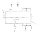
- FIG. 3 is a top view of the roll 10 (without interlayer 40 for purposes of facilitating explanation).
- camber is the only factor affecting the lateral offset of the roll 10.
- core 12 is rotated about central longitudinal axis 13
- glass ribbon 20 is wound into roll 10. If there were no camber in the glass ribbon 20, the central longitudinal axis 22 of the glass ribbon 20 would remain substantially perpendicular to the central longitudinal axis 13, whereby the glass ribbon 20 would be wound into roll 10 having straight side walls, i.e., there would be little if any lateral offset.
- the glass ribbon 20 is continuously curved so that the longitudinal axis 22 is bent in the direction shown in an exaggerated manner by double headed arrow 15, thereby producing forces on the glass ribbon 20 making it tend to shift in the direction of arrow 5, whereby the sides of roll 10 become angled, and the lateral offset may increase.
- interleaf material Some pertinent characteristics of the interleaf material are its coefficient of friction with the glass ribbon being wound, the width of the interlayer with respect to that of the glass ribbon, compliance, and thickness.
- an interlayer with a static coefficient of friction of greater than or equal to about 3.0 (as measured with a vertical force of 0.5N), or from about 3.0 to about 4.6 (as measured with a vertical force of 0.5 N), or from about 3.4 to about 4.2 (as measured with a vertical force of 0.5N) with the glass ribbon assists in maintaining a roll with straight side walls.
- a static coefficient of friction in this range assists in producing forces that resist the effects of camber as described above in connection with FIG. 2 , and that assist in holding the layers of the roll in place during handling. The higher the static coefficient of friction, the more resistant to the effects of camber the roll will be, and the more stable during handling the roll will be.
- a lateral offset 9 of less than or equal to 1.6 mm can be obtained even in rolls 10 having up to about 150 layers or more of glass ribbon 20, for example, more than 2 layers, more than 3 layers, more than 4 layers, more than 5 layers, more than 6 layers, more than 7 layers, more than 8 layers, more than 9 layers, more than 10 layers, more than 15 layers, more than 20 layers, more than 30 layers, more than 40 layers, more than 50 layers, more than 60 layers, more than 70 layers, more than 80 layers, more than 90 layers, more than 100 layers, more than 110 layers, more than 120 layers, more than 130 layers, more than 140 layers, from 1-150 layers, from 2-150 layers, from 3-150 layers, from 4-150 layers, from 5-150 layers, from 6-150 layers, from 7-150 layers, from 8-150 layers, from 9-150 layers, from 10-150 layers, from 15-150 layers, from 20-150 layers, from 30-150 layers, from 40-150 layers, from 50-150 layers, from 60-150 layers, from 70-150 layers, from 80-150 layers, from 90
- Width and thickness of the interlayer material 40 also assist in producing a roll 10 with straight side walls.
- the width 42 of the interlayer 40 may be chosen to as to be less than the width 24 of the glass ribbon.
- the glass ribbon 20 has more freedom to pivot in the direction of double-headed arrow 8 due to the effects of differential cross web thickness and/or camber thereby reducing the amount of compression required to compensate for these effects.
- the interlayer 40 is placed away from the outboard portions 28 of the glass ribbon 20. Accordingly, by placing the interlayer material 41, 43 on the central portion of the glass ribbon 20 in which there is less likelihood of thickness variation, the roll 10 becomes more stable and more likely to have straight side walls.
- the strips 41, 43 may be placed so that the distance 45 is centered within ⁇ 10% from the center 7 (in the width-wise direction) of the glass ribbon 20. See FIG. 4 .
- the strips may be placed so that the overall width 42 is centered within ⁇ 10% from the center 7 of the glass ribbon 20. See FIG. 2 .
- the strips are placed away from the outboard portions 28.
- the latter case may be used with either two strips 41, 43, or when more or less than two strips are present.
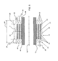
- FIG. 5 shows alternative embodiments of each the glass ribbon 20 and the interlayer 40.
- the glass ribbon 20 shown in this figure may be used with the interlayer material of the other figures, and the interlayer 40 in this figure may be used with the glass ribbon 20 of the other figures.
- the main differences from the other figures lie in the physical configuration of the glass ribbon 20 and interlayer material 40. Accordingly, for ease in description mainly the differences will be described with the understanding that the remaining properties, and like characteristics as denoted by like reference numerals, may remain the same.
- the glass ribbon 20 is shown as including beads 30 having a thickness 32.
- the interlayer material 40 is formed as one continuous piece having a width 42, outside edges 44, and a thickness 46.
- the thickness 46 is chosen so that when the interlayer 40 is subject to a pressure between the layers in the roll, as described below, the interlayer 40 maintains a gap 34 between adjacent beads 30, thereby allowing the glass ribbon 20 to be wound into roll 10 without damage from the beads 30 contacting one another.
- the width 42 is less than the width 24, and the interlayer material 40 is not disposed on the outboard end portions 28 wherein the thickness variation in the glass ribbon is exaggerated due to the presence of the beads 30.
- the width 42 may be centered, within ⁇ 10% of the center 7 of the glass ribbon 20.
- the compliance of the interlayer material 40 plays a role in forming a roll 10 with straight side walls by compensating for thickness variation in the glass ribbon 20.
- the effects of thickness variation will be described with reference to FIG. 6 .
- the glass ribbon is shown with a thickness 27 on a left-hand edge and a second, greater, thickness 29 on the right-hand edge. If the interlayer 40 were not compliant, but rigid, the greater thickness 29 would cause the glass ribbon 20 to tilt upwards from left to right (as when viewing the top portion of the roll 10 as shown in FIG. 6 ).
- the interlayer 40 compensates for the difference in thicknesses 27, 29. More specifically, the interlayer 40 would compress more when adjacent to the portion of the glass ribbon 20 having a greater thickness 29, and compress less when adjacent to the portion of the glass ribbon 20 having the smaller thickness 27. That is, as shown in FIG.
- the interlayer 40 under roll compression, the interlayer 40 would assume a smaller thickness 49 the right-hand side, and a greater thickness 47 on the left-hand side, thereby allowing the layer 23 to assume an approximately horizontal orientation despite its difference in thicknesses 27, 29. In this case, thickness 49 is still sufficient to maintain a suitable gap 34 between the beads 30.
- a suitable stiffness for the interlayer material 40 was found to be less than or equal to about 28.14 N/mm, or less than or equal to about 27.12 N/mm, or less than or equal to about 26.1 N/mm, wherein the lower bound for all ranges was greater than zero.
- the interlayer 40 may be formed from, for example, a polyethylene foam (either open or closed cell), a corrugated paper material, or a sheet of soft polyvinyl material having an embossed or textured surface.
- the rolling conditions also play a part in forming a roll with straight side walls.
- Some pertinent rolling conditions are web tension and pressure between the layers in the roll.
- the inventors found that using a low web tension and a low pressure between the layers produced straighter side walls in the roll-i.e., where "low” was lower than typically expected. More particularly, a web tension of greater than 0 pounds per linear inch (0 kg/cm), but 0.25 pounds per linear inch (0.45 kg/cm) or less, produced straight side walls on the roll.
- a pressure between the layers in the roll of 10 pounds per square inch (0.703 kg/square cm) or less, but greater than 0 pounds per square inch (0 kg/square cm), produced straight side walls on the roll.
- Another pressure between the layers in the roll of 7 pounds per square inch (0.492 kg/square cm) or less, but greater than 0 pounds per square inch (0 kg/square cm), also produced straight side walls on the roll. Further, the above-noted coefficients of friction between the interlayer and glass ribbon facilitated using the above-noted unusually low web tension and pressure between the layers in the roll.
- the web tension and pressure ranges may be used with any of the configurations of glass ribbon 20 and interlayer material 40 described herein to produce the above-noted minimal lateral offsets 9, even when the roll includes up to about 150 layers or more of glass ribbon 20.
- the core is shown without flanges on its ends, flanges could be present. Further, the flanges could be permanently attached to the core, or could be removable.
- a layer of glass ribbon is shown as being the outermost layer of the roll, it need not be. That is, the interlayer may be wound one or more times around the outer-most layer of glass ribbon in order to protect that layer.
- an interlayer is shown as being the inner-most layer of the roll, it need not be; the inner-most layer of glass ribbon could be the inner-most layer of the roll. Nonetheless, it is preferable to have an interlayer as the inner-most layer of the roll in order to protect the inner-most layer of glass ribbon.
- center 7 of the glass ribbon 20 is shown as being aligned with the center 14 of the core 12, such need not be the case.
Abstract
Description
- This application claims the priority of
US Provisional Application Serial No. 61/349,438 filed on May 28, 2010 - The invention is directed to a roll of flexible glass and a method for rolling the glass. More particularly, the invention is directed to a roll of flexible glass ribbon wound together with an interlayer, and to a method for rolling them together.
- Although formed as a continuous ribbon, glass is typically segmented into sheets as soon as it has cooled and solidified. Recent product trends-in ePaper front plane substrates, protective cover sheets in photovoltaic modules, touch sensors, solid state lighting, and electronics, for example-have resulted in requirements for thinner and thinner glass. As glass thicknesses continues to decrease, however, these sheets become more flexible. This creates a challenge from a handling perspective, particularly for glass of 0.3 mm or thinner. Accordingly, there have been attempts to roll thin glass as a manner of facilitating handling. However, there are several unique features of glass that create challenges for successfully implementing a rolling process. First the edge "beads" of the glass, as formed, are substantially thicker than the constant thickness area in between. Second glass is extremely sensitive to surface defects. These defects create stress points that generate cracks and lead to breakage. Thus it is not advisable to have direct surface to surface contact of glass to itself, as is typical in a spooled roll of material. The challenges from these first two characteristics have been addressed by using various interleaf materials between layers of the glass ribbon when winding. Third, as noticed by the inventors of the present disclosure, and which has gone unaddressed-in terms of their effect on rolling thin glass ribbon, i.e. 0.3 mm or thinner-to this point as far as the present inventors are aware, is that the forming process can introduce differential thickness across the width of the glass ribbon and/or camber (continuous curvature in one direction caused by differential cooling between the two edge beads). When rolling a glass ribbon with differential cross-ribbon thickness and/or camber, lateral forces are generated in the spooled roll that result in angled, rather than straight, side walls on the wound roll. In some cases, the angle of the side wall may lead to the glass ribbon contacting a flange of a spool onto which the glass ribbon is being wound, thereby risking damage to the glass ribbon. Additionally, the angled side wall of the spool leads to difficulties in processing, when unwinding the roll to use the glass ribbon in a continuous manufacturing process. Accordingly, there is a need for rolls of wound glass ribbon having straighter side walls.
- In order to form a roll of wound glass ribbon having straight side walls, the inventors have found that the effects of the differential cross-ribbon thickness and/or camber, among other things, can be counteracted by appropriately choosing an interleaf material and rolling conditions.
- Some pertinent characteristics of the interleaf material are its coefficient of friction with the glass ribbon being wound, the width of the interlayer with respect to the glass ribbon, compliance, and thickness. First, choosing an interleaf material with a sufficient coefficient of friction between it and the glass ribbon being wound assists in providing a force to resist that produced by the differential thickness and/or camber. Additionally, a sufficient coefficient of friction assists in maintaining roll integrity during subsequent handling, even in rolls that have very low pressure between the layers in the roll, as discussed below. More specifically, a beneficial static coefficient of friction between the interlayer and the glass ribbon was found to be greater than or equal to about 3.0 (as measured with a vertical force of 0.5N), another was found to be from about 3.0 to about 4.6 (as measured with a vertical force of 0.5 N), and another was found to be from about 3.4 to about 4.2 (as measured with a vertical force of 0.5N). Second, an interlayer having a width less than that of the glass ribbon allows the contact between the interlayer and the glass ribbon to occur in the central area of the glass ribbon wherein there is low thickness variation. Additionally, these relative widths allow the glass ribbon some freedom to pivot about its longitudinal axis, which may result from the effects of camber in the glass ribbon. Third, the interlayer should be thickness compliant, or have some give to it when compressed, in order to absorb any thickness differences that may be present in the central portion of the glass ribbon. A suitable stiffness for the interlayer material was found to be less than or equal to about 28.14 N/mm, or less than or equal to about 27.12 N/mm, or less than or equal to about 26.1 N/mm, wherein the lower bound for all ranges was greater than zero. In order to achieve the above-noted stiffness, the interlayer may be formed from, for example, a polyethylene foam (either open or closed cell), a corrugated paper material, or a sheet of soft polyvinyl material having an embossed or textured surface. Fourth, when winding a glass ribbon having beads on its edges, the interlayer is chosen to have a sufficient thickness, when compressed under the rolling conditions as discussed below, so that the beads do not touch one another. The ability to roll the glass ribbon with its beads on facilitates manufacture of the glass ribbon.
- Some pertinent rolling conditions are web tension and pressure between the layers in the roll. More specifically, the inventors found that typical web winding process parameters of 1-2 pounds per linear inch (0.179 to 0.357 kg/cm) of web tension, and 15-50 pounds per square inch (1.054 to 3.515 kg/square cm) of pressure between the layers, when used with a thin glass ribbon produced angled side walls in the roll. Further, contrary to conventional wisdom, the inventors found that increasing the web tension and pressure between the layers actually made the side wall characteristics worse. Surprisingly, the inventors found that using lower web tension and lower pressure between the layers produced straighter side walls in the roll. More particularly, a web tension of greater than 0 pounds per linear inch (0 kg/cm), but 0.25 pounds per linear inch (0.45 kg/cm) or less, produced straight side walls on the roll. Additionally, a pressure between the layers in the roll of 10 pounds per square inch (0.703 kg/square cm) or less, but greater than 0 pounds per square inch (0 kg/square cm), produced straight side walls on the roll. Another pressure between the layers in the roll of 7 pounds per square inch (0.492 kg/square cm) or less, but greater than 0 pounds per square inch (0 kg/square cm), also produced straight side walls on the roll. Further, the above-noted coefficients of friction between the interlayer and glass ribbon facilitated using the above-noted unusually low web tension and pressure between the layers in the roll. Also, if there is not sufficient interlayer friction due to a combination of too low a pressure between the layers and/or too low a coefficient of friction, the successive wraps can slide laterally on each other, undesirably creating a "telescoped" side wall.
- Additional features and advantages will be set forth in the detailed description which follows, and in part will be readily apparent to those skilled in the art from the description or recognized by practicing the invention as exemplified in the written description and the appended drawings. It is to be understood that both the foregoing general description and the following detailed description are merely exemplary of the invention, and are intended to provide an overview or framework to understanding the nature and character of the invention as it is claimed.
- The accompanying drawings are included to provide a further understanding of principles of the invention, and are incorporated in and constitute apart of this specification. The drawings illustrate one or more embodiment(s), and together with the description serve to explain, by way of example, principles and operation of the invention. It is to be understood that various features of the invention disclosed in this specification and in the drawings can be used in any and all combinations. By way of non-limiting example the various features of the invention may be combined with one another as set forth in the following aspects:
- According to a first aspect, there is provided a roll of glass ribbon, comprising:
- a glass ribbon;
- an interlayer wound together with the glass ribbon, wherein the glass ribbon has a thickness of 0.3 mm or less,
- According to a second aspect, there is provided the roll according to Aspect 1 or aspect 31, wherein the static coefficient of friction is from 3.0 to 4.6 (as measured with a vertical force of 0.5 N).
- According to a third aspect, there is provided the roll according to Aspect 1 or aspect 31, wherein the static coefficient of friction is from 3.4 to 4.2 (as measured with a vertical force of 0.5 N).
- According to a fourth aspect, there is provided the roll according to any one of Aspects 1-3 or 31-36, wherein the stiffness of the interlayer is less than or equal to 28.14 N/mm.
- According to a fifth aspect, there is provided the roll according to any one of Aspects 1-3 or 31-36, wherein the stiffness of the interlayer is less than or equal to 27.12 N/mm.
- According to a sixth aspect, there is provided the roll according to any one of Aspects 1-3 or 31, wherein the stiffness of the interlayer is less than or equal to 26.1 N/mm.
- According to a seventh aspect, there is provided the roll according to any one of Aspects 1-6, wherein the pressure between successive layers of glass ribbon is less than or equal to 10 pounds per square inch (0.703 kg/square cm).
- According to an eighth aspect, there is provided the roll according to any one of Aspects 1-7 or 31-36, wherein the interlayer and glass ribbon are wound so that a lateral offset between an inner-most layer of the glass ribbon and an outer-most layer of glass ribbon is less than or equal to 1.6 mm, even when the roll includes up to 150 or more layers of glass ribbon.
- According to a ninth aspect, there is provided the roll according to any one of Aspects 1-8 or 31-36, wherein the interlayer comprises a first portion and a second portion disposed at a distance from one another and having a width, wherein the width is centered within ± 10% of the center of the glass ribbon,
wherein the glass ribbon has an outboard end portion, and
further wherein there is no interlayer disposed on the outboard end portion. - According to a tenth aspect, there is provided the roll according to any one of Aspects 1-8 or 31-36, wherein the interlayer has a first width, the glass ribbon has a second width and an outboard end portion,
wherein the first width is less than the second width, and
further wherein there is no interlayer disposed on the outboard end portion. - According to an eleventh aspect, there is provided the roll according to any one of Aspects 1-10 or 31-36, wherein the glass ribbon comprises a bead on one of its edges.
- According to a twelfth aspect, there is provided the roll according to
Aspect 11, wherein the interlayer has a thickness when compressed at a roll-winding pressure up to 70 kPa (10 psi), the bead has a thickness, and the interlayer thickness is greater than a difference between the bead thickness and the ribbon thickness. - According to a thirteenth aspect, there is provided the roll according to any one of Aspects 1-12 , wherein the interlayer comprises polyethylene foam.
- According to a fourteenth aspect, there is provided the roll according to any one of Aspects 1-13, further comprising a core around which the glass ribbon and the interlayer are wound.
- According to a fifteenth aspect, there is provided a method of winding a glass ribbon, comprising:
- winding an interlayer together with a glass ribbon, wherein the glass ribbon has a thickness of 0.3 mm or less,
- wherein the static coefficient of friction between the interlayer and the glass ribbon is greater than or equal to 3.0 (as measured with a vertical force of 0.5 N).
- According to a sixteenth aspect, there is provided the method according to
Aspect 15, wherein the static coefficient of friction is from 3.0 to 4.6 (as measured with a vertical force of 0.5 N). - According to a seventeenth aspect, there is provided the method according to
Aspect 15, wherein the static coefficient of friction is from 3.4 to 4.2 (as measured with a vertical force of 0.5 N). - According to an eighteenth aspect, there is provided the method according to any one of Aspects 15-17, wherein the stiffness of the interlayer is less than or equal to 28.14 N/mm.
- According to a nineteenth aspect, there is provided the method according to any one of Aspects 15-17, wherein the stiffness of the interlayer is less than or equal to 27.12 N/mm.
- According to a twentieth aspect, there is provided the method according to any one of Aspects 15-17, wherein the stiffness of the interlayer is less than or equal to 26.1 N/mm.
- According to a twenty first aspect, there is provided the method according to any one of Aspects 15-20, wherein the winding is performed so that a resulting pressure between successive layers of glass ribbon is greater than zero pounds per square inch (0 kg/square cm) and is less than or equal to 10 pounds per square inch (0.703 kg/square cm).
- According to a twenty second aspect, there is provided the method a according to any one of Aspects 15-21, wherein the winding is performed to that a resulting pressure between successive layers of glass ribbon is greater than zero pounds per square inch (0 kg/square cm) and is less than or equal to 7 pounds per square inch (0.492 kg/square cm).
- According to a twenty third aspect, there is provided the method according to any one of Aspects 15-22, wherein the winding is performed with a web tension of greater than zero pounds per linear inch (0 kg/cm) and of less than or equal to 0.25 pounds per linear inch (.045 kg/cm) on the glass ribbon.
- According to a twenty fourth aspect, there is provided the method according to any one of Aspects 15-23, wherein the winding is performed so that the glass ribbon is disposed in an inner-most layer and an outer-most layer, wherein a lateral offset between the inner-most layer and the outer-most layer is less than or equal to 1.6 mm, evening rolls having up to about 150 layers or more of glass ribbon 20, for example, more than 2 layers, more than 3 layers, more than 4 layers, more than 5 layers, more than 6 layers, more than 7 layers, more than 8 layers, more than 9 layers, more than 10 layers, more than 15 layers, more than 20 layers, more than 30 layers, more than 40 layers, more than 50 layers, more than 60 layers, more than 70 layers, more than 80 layers, more than 90 layers, more than 100 layers, more than 110 layers, more than 120 layers, more than 130 layers, more than 140 layers, from 1-150 layers, from 2-150 layers, from 3-150 layers, from 4-150 layers, from 5-150 layers, from 6-150 layers, from 7-150 layers, from 8-150 layers, from 9-150 layers, from 10-150 layers, from 15-150 layers, from 20-150 layers, from 30-150 layers, from 40-150 layers, from 50-150 layers, from 60-150 layers, from 70-150 layers, from 80-150 layers, from 90-150 layers, from 100-150 layers, from 110-150 layers, from 120-150 layers, from 130-150 layers, or from 140-150 layers.
- According to a twenty fifth aspect, there is provided the method according to any one of Aspects 15-24, wherein the interlayer comprises a first portion and a second portion disposed at a distance from one another and having a width, wherein the width is centered within ± 10% of the center of the glass ribbon,
wherein the glass ribbon has an outboard end portion, and
further wherein there is no interlayer disposed on the outboard end portion. - According to a twenty sixth aspect, there is provided the method according to any one of Aspects 15-24, wherein the interlayer has a first width, the glass ribbon has a second width and an outboard end portion,
wherein the first width is less than the second width, and
further wherein there is no interlayer disposed on the outboard end portion. - According to a twenty seventh aspect, there is provided the method according to any one of Aspects 15-26, wherein the glass ribbon comprises a bead on one of its edges.
- According to a twenty eighth aspect, there is provided the method according to
Aspect 27, wherein the interlayer has a thickness when compressed at a roll-winding pressure up to 70 kPa (10 psi), the bead has a thickness, and the interlayer thickness is greater than a difference between the bead thickness and the ribbon thickness. - According to a twenty ninth aspect, there is provided the method according to any one of Aspects 15-28, wherein the interlayer comprises polyethylene foam.
- According to a thirtieth aspect, there is provided the method according to any one of Aspects 15-29, wherein the winding comprises winding the glass ribbon and interlayer around a core.
- According to a thirty first aspect, there is provided a roll of material comprising: interleaving material wound together with glass ribbon, wherein a pressure between layers in the roll is ≤ 10 pounds per square inch (0.703 kg/ square cm), and is greater than 0 pounds per square inch (0 kg/ square cm).
- According to a thirty second aspect, there is provided the roll of material of aspect 31, wherein the pressure between layers in the roll is ≤ 7 pounds per square inch (0.492 kg/ square cm), and is greater than 0 pounds per square inch (0 kg/ square cm).
- According to a thirty third aspect, there is provided the roll of material of any one of aspect 31 or
aspect 32, wherein the interleaving material is thickness compliant. - According to a thirty fourth aspect, there is provided the roll of material of aspect 33, wherein the interleaving material is polyethylene foam.
- According to a thirty fifth aspect, there is provided the roll of material of any one of aspects 31-34, wherein the inter-layer roll pressure is approximately constant throughout the roll.
- According to a thirty sixth aspect, there is provided the roll of material of any one of aspects 31-35, wherein the glass ribbon has a thickness ≤ 0.3 mm.
-
-
FIG. 1 is a schematic drawing of a roll winding process. -
FIG. 2 is a schematic cross-section of a roll of glass ribbon and interlayer material as taken along line 2-2 inFIG. 1 . -
FIG. 3 is a schematic top view of the roll inFIG. 1 . -
FIG. 4 is schematic cross-section of a roll of glass ribbon and interlayer similar to that shown inFIG. 2 . -
FIG. 5 is a schematic cross-section of a roll of glass ribbon and interlayer material, similar to that shown inFIG. 2 , but according to another embodiment. -
FIG. 6 is a schematic cross-section of a roll of glass ribbon and interlayer material, similar to that shown inFIG. 2 , but according to another embodiment. - In the following detailed description, for purposes of explanation and not limitation, example embodiments disclosing specific details are set forth to provide a thorough understanding of various principles of the present invention. However, it will be apparent to one having ordinary skill in the art, having had the benefit of the present disclosure, that the present invention may be practiced in other embodiments that depart from the specific details disclosed herein. Moreover, descriptions of well-known devices, methods and materials may be omitted so as not to obscure the description of various principles of the present invention. Finally, wherever applicable, like reference numerals refer to like elements.
- Ranges can be expressed herein as from "about" one particular value, and/or to "about" another particular value. When such a range is expressed, another embodiment includes from the one particular value and/or to the other particular value. Similarly, when values are expressed as approximations, by use of the antecedent "about," it will be understood that the particular value forms another embodiment. It will be further understood that the endpoints of each of the ranges are significant both in relation to the other endpoint, and independently of the other endpoint.
- Directional terms as used herein-for example up, down, right, left, front, back, top, bottom-are made only with reference to the figures as drawn and are not intended to imply absolute orientation.
- Unless otherwise expressly stated, it is in no way intended that any method set forth herein be construed as requiring that its steps be performed in a specific order. Accordingly, where a method claim does not actually recite an order to be followed by its steps or it is not otherwise specifically stated in the claims or descriptions that the steps are to be limited to a specific order, it is no way intended that an order be inferred, in any respect. This holds for any possible non-express basis for interpretation, including: matters of logic with respect to arrangement of steps or operational flow; plain meaning derived from grammatical organization or punctuation; the number or type of embodiments described in the specification.
- As used herein, the singular forms "a," "an" and "the" include plural referents unless the context clearly dictates otherwise. Thus, for example, reference to a "component" includes aspects having two or more such components, unless the context clearly indicates otherwise.
-
FIG. 1 is a schematic drawing of a process for rolling aglass ribbon 20. Theglass ribbon 20 is-after being produced by any suitable method, for example, down-draw, fusion draw, up-draw, slot draw, or float-fed along direction 1 towardroll 10, which rotates in adirection 11. At the same time, aninterlayer material 40 is unwound fromroll 2 rotating indirection 3 and is fed along direction 4. Theinterlayer 40 is positioned relative to theroll 10 byguide rollers 16. According to one aspect, theinterlayer 40 is wound around a core 12 (seeFIG. 2 ) one or more times beforeglass ribbon 20 is fed into thenip 6 between successive layers ofinterlayer 40. According to another aspect, theglass ribbon 20 is wound around thecore 12 and theinterlayer 40 is then fed into a nip between successive layers ofglass ribbon 20, although the former aspect is preferred. In either case, theglass ribbon 20 andinterlayer 40 are wound together to form aroll 10 aroundcore 12. The core 12 may remain in theroll 10 or be removed therefrom. When thecore 12 is to remain in theroll 10, the inner-most layer (either intcrlaycr material or glass ribbon) may be attached to thecore 12. Keeping the core 12 in theroll 10, and attaching theinterlayer material 40 to the core 12 assists in preventing the entire spooled glass / interlayer pack from side shifting during unwinding in subsequent processes steps. - A cross section of the
roll 10 is shown inFIG. 2 , which is a view taken along line 2-2 inFIG. 1 , but which omits the top interlayer so as to make illustration more clear. As seen inFIG. 2 , theroll 10 includesglass ribbon 20,interlayer 40, and optionally acore 12 around which theglass ribbon 20 andinterlayer 40 are wound. Thecore 12, when present, includes a centrallongitudinal axis 13, and acentral axis 14 in the width-wise direction of thecore 12. - The
glass ribbon 20 is disposed in aninner-most layer 21, anintermediate layer 23, and anoutermost layer 25. Although only three layers are shown, there may be any suitable number (including zero) ofintermediate layers 23 betweenlayers glass ribbon 20 has athickness 26, which may be from about 50 microns to about 300 microns, and awidth 24. Theglass ribbon 20 also includesoutboard end portions 28 in which there is the greatest likelihood of thickness variation due to the forming process. Further, the glass ribbon includesedges 204 which maybe as-formed edges or cut edges. Still further, there is a lateral offset 9 between theinner-most layer 21 and theouter-most layer 25 of the glass ribbon. A lateral offset 9 may also exist between any two adjacent layers of theglass ribbon 20. Moreover, as shown inFIG. 3 , theglass ribbon 20 includes a centrallongitudinal axis 22. - As shown in
FIG. 2 , according to one aspect, theinterlayer material 40 is formed as afirst strip 41 and asecond strip 43 separated by adistance 45. Theinterlayer 40 includes anoverall width 42 betweenoutside edges 44 on thestrips interlayer 40 includes athickness 46. - The effects of camber (continuous curvature in one direction caused by differential cooling between the two edge beads during the forming process, for example) will be explained with reference to
FIG. 3 , which is a top view of the roll 10 (withoutinterlayer 40 for purposes of facilitating explanation). For simplicity in this discussion, it is assumed that camber is the only factor affecting the lateral offset of theroll 10. Ascore 12 is rotated about centrallongitudinal axis 13,glass ribbon 20 is wound intoroll 10. If there were no camber in theglass ribbon 20, the centrallongitudinal axis 22 of theglass ribbon 20 would remain substantially perpendicular to the centrallongitudinal axis 13, whereby theglass ribbon 20 would be wound intoroll 10 having straight side walls, i.e., there would be little if any lateral offset. However, in the presence of camber, theglass ribbon 20 is continuously curved so that thelongitudinal axis 22 is bent in the direction shown in an exaggerated manner by double headedarrow 15, thereby producing forces on theglass ribbon 20 making it tend to shift in the direction ofarrow 5, whereby the sides ofroll 10 become angled, and the lateral offset may increase. - In order to form a
roll 10 of wound glass ribbon having straight side walls, i.e., one with a small lateral offset 9 (from layer to adjacent layer of the glass ribbon, as well as overall frominner-most layer 21 toouter-most layer 25 of glass ribbon), the inventors have found that the effects of camber, among other things, can be counteracted by appropriately choosing an interleaf material and rolling conditions. - Some pertinent characteristics of the interleaf material are its coefficient of friction with the glass ribbon being wound, the width of the interlayer with respect to that of the glass ribbon, compliance, and thickness.
- The inventors have found that choosing an interlayer with a static coefficient of friction of greater than or equal to about 3.0 (as measured with a vertical force of 0.5N), or from about 3.0 to about 4.6 (as measured with a vertical force of 0.5 N), or from about 3.4 to about 4.2 (as measured with a vertical force of 0.5N) with the glass ribbon assists in maintaining a roll with straight side walls. A static coefficient of friction in this range assists in producing forces that resist the effects of camber as described above in connection with
FIG. 2 , and that assist in holding the layers of the roll in place during handling. The higher the static coefficient of friction, the more resistant to the effects of camber the roll will be, and the more stable during handling the roll will be. If the static coefficient of friction becomes too small, then there are not produced sufficient forces to resist the effects of camber in the glass ribbon as it is wound and the walls of the roll become angled, stepped, or otherwise no longer straight. Further, if the static coefficient of friction is too low, there are not sufficient forces to hold the layers of the roll in place during handling of the roll. - By choosing an
interlayer material 40 having a static coefficient of friction within the above-noted ranges, there can be produced a roll having a lateral offset 9 (seeFIG. 2 ) between aninner-most layer 21 of theglass ribbon 20 and anouter-most layer 25 of the glass ribbon of less than or equal to 1.6 mm. A lateral offset 9 of less than or equal to 1.6 mm can be obtained even in rolls 10 having up to about 150 layers or more of glass ribbon 20, for example, more than 2 layers, more than 3 layers, more than 4 layers, more than 5 layers, more than 6 layers, more than 7 layers, more than 8 layers, more than 9 layers, more than 10 layers, more than 15 layers, more than 20 layers, more than 30 layers, more than 40 layers, more than 50 layers, more than 60 layers, more than 70 layers, more than 80 layers, more than 90 layers, more than 100 layers, more than 110 layers, more than 120 layers, more than 130 layers, more than 140 layers, from 1-150 layers, from 2-150 layers, from 3-150 layers, from 4-150 layers, from 5-150 layers, from 6-150 layers, from 7-150 layers, from 8-150 layers, from 9-150 layers, from 10-150 layers, from 15-150 layers, from 20-150 layers, from 30-150 layers, from 40-150 layers, from 50-150 layers, from 60-150 layers, from 70-150 layers, from 80-150 layers, from 90-150 layers, from 100-150 layers, from 110-150 layers, from 120-150 layers, from 130-150 layers, or from 140-150 layers. This small amount of lateral offset 9 makes the roll easy to unwind into a manufacturing process. - Width and thickness of the
interlayer material 40 also assist in producing aroll 10 with straight side walls. For example, with reference toFIG. 2 , thewidth 42 of theinterlayer 40 may be chosen to as to be less than thewidth 24 of the glass ribbon. By choosing thewidth 42 to be less than thewidth 24, theglass ribbon 20 has more freedom to pivot in the direction of double-headedarrow 8 due to the effects of differential cross web thickness and/or camber thereby reducing the amount of compression required to compensate for these effects. Additionally, theinterlayer 40 is placed away from theoutboard portions 28 of theglass ribbon 20. Accordingly, by placing theinterlayer material glass ribbon 20 in which there is less likelihood of thickness variation, theroll 10 becomes more stable and more likely to have straight side walls. Further, thestrips distance 45 is centered within ±10% from the center 7 (in the width-wise direction) of theglass ribbon 20. SeeFIG. 4 . Alternatively, or in addition thereto, the strips may be placed so that theoverall width 42 is centered within ±10% from thecenter 7 of theglass ribbon 20. SeeFIG. 2 . In this latter case, again the strips are placed away from theoutboard portions 28. The latter case may be used with either twostrips -
FIG. 5 shows alternative embodiments of each theglass ribbon 20 and theinterlayer 40. It is to be understood that theglass ribbon 20 shown in this figure may be used with the interlayer material of the other figures, and theinterlayer 40 in this figure may be used with theglass ribbon 20 of the other figures. The main differences from the other figures lie in the physical configuration of theglass ribbon 20 andinterlayer material 40. Accordingly, for ease in description mainly the differences will be described with the understanding that the remaining properties, and like characteristics as denoted by like reference numerals, may remain the same. In this figure theglass ribbon 20 is shown as includingbeads 30 having athickness 32. Further, theinterlayer material 40 is formed as one continuous piece having awidth 42, outside edges 44, and athickness 46. Thethickness 46 is chosen so that when theinterlayer 40 is subject to a pressure between the layers in the roll, as described below, theinterlayer 40 maintains agap 34 betweenadjacent beads 30, thereby allowing theglass ribbon 20 to be wound intoroll 10 without damage from thebeads 30 contacting one another. Again, as noted above, thewidth 42 is less than thewidth 24, and theinterlayer material 40 is not disposed on theoutboard end portions 28 wherein the thickness variation in the glass ribbon is exaggerated due to the presence of thebeads 30. Again, thewidth 42 may be centered, within ±10% of thecenter 7 of theglass ribbon 20. - Lastly, as far as the characteristics of the interlayer, the compliance of the
interlayer material 40 plays a role in forming aroll 10 with straight side walls by compensating for thickness variation in theglass ribbon 20. The effects of thickness variation will be described with reference toFIG. 6 . In this figure, ignoringbeads 30 for the moment, the glass ribbon is shown with athickness 27 on a left-hand edge and a second, greater,thickness 29 on the right-hand edge. If theinterlayer 40 were not compliant, but rigid, thegreater thickness 29 would cause theglass ribbon 20 to tilt upwards from left to right (as when viewing the top portion of theroll 10 as shown inFIG. 6 ). In so tilting,layer 23 would then tend to push thenext layer 23 in the direction ofarrow 5 causing the side wall of theroll 10 to shift rightward. The effects of the thickness difference would build on one another as it is likely that the same differences inthickness ribbon 20 is formed. However, by choosing acompliant interlayer material 40, theinterlayer 40 compensates for the difference inthicknesses interlayer 40 would compress more when adjacent to the portion of theglass ribbon 20 having agreater thickness 29, and compress less when adjacent to the portion of theglass ribbon 20 having thesmaller thickness 27. That is, as shown inFIG. 6 , under roll compression, theinterlayer 40 would assume asmaller thickness 49 the right-hand side, and agreater thickness 47 on the left-hand side, thereby allowing thelayer 23 to assume an approximately horizontal orientation despite its difference inthicknesses thickness 49 is still sufficient to maintain asuitable gap 34 between thebeads 30. A suitable stiffness for theinterlayer material 40 was found to be less than or equal to about 28.14 N/mm, or less than or equal to about 27.12 N/mm, or less than or equal to about 26.1 N/mm, wherein the lower bound for all ranges was greater than zero. In order to achieve the above-noted stiffness, theinterlayer 40 may be formed from, for example, a polyethylene foam (either open or closed cell), a corrugated paper material, or a sheet of soft polyvinyl material having an embossed or textured surface. - The rolling conditions also play a part in forming a roll with straight side walls. Some pertinent rolling conditions are web tension and pressure between the layers in the roll. Surprisingly, the inventors found that using a low web tension and a low pressure between the layers produced straighter side walls in the roll-i.e., where "low" was lower than typically expected. More particularly, a web tension of greater than 0 pounds per linear inch (0 kg/cm), but 0.25 pounds per linear inch (0.45 kg/cm) or less, produced straight side walls on the roll. Additionally, a pressure between the layers in the roll of 10 pounds per square inch (0.703 kg/square cm) or less, but greater than 0 pounds per square inch (0 kg/square cm), produced straight side walls on the roll. Another pressure between the layers in the roll of 7 pounds per square inch (0.492 kg/square cm) or less, but greater than 0 pounds per square inch (0 kg/square cm), also produced straight side walls on the roll. Further, the above-noted coefficients of friction between the interlayer and glass ribbon facilitated using the above-noted unusually low web tension and pressure between the layers in the roll. The web tension and pressure ranges may be used with any of the configurations of
glass ribbon 20 andinterlayer material 40 described herein to produce the above-notedminimal lateral offsets 9, even when the roll includes up to about 150 layers or more ofglass ribbon 20. - It should be emphasized that the above-described embodiments of the present invention, particularly any "preferred" embodiments, are merely possible examples of implementations, merely set forth for a clear understanding of various principles of the invention. Many variations and modifications may be made to the above-described embodiments of the invention without departing substantially from the spirit and various principles of the invention. All such modifications and variations are intended to be included herein within the scope of this disclosure and the present invention and protected by the following claims.
- For example, although the core is shown without flanges on its ends, flanges could be present. Further, the flanges could be permanently attached to the core, or could be removable.
- Additionally, although three layers of interlayer and three layers of glass ribbon are shown as being wound on a roll, any suitable number of layers of either may be present.
- Further, although a layer of glass ribbon is shown as being the outermost layer of the roll, it need not be. That is, the interlayer may be wound one or more times around the outer-most layer of glass ribbon in order to protect that layer. Similarly, although an interlayer is shown as being the inner-most layer of the roll, it need not be; the inner-most layer of glass ribbon could be the inner-most layer of the roll. Nonetheless, it is preferable to have an interlayer as the inner-most layer of the roll in order to protect the inner-most layer of glass ribbon.
- Still further, although the
center 7 of theglass ribbon 20 is shown as being aligned with thecenter 14 of the core 12, such need not be the case.
Claims (10)
- A roll of material comprising:interleaving material wound together with glass ribbon, wherein a pressure between layers in the roll is ≤ 10 pounds per square inch (0.703 kg/ square cm), and is greater than 0 pounds per square inch (0 kg/ square cm).
- The roll according to claim 1, wherein the stiffness of the interleaving material is less than or equal to 28.14 N/mm.
- The roll according to claim 1 or 2, wherein the interleaving material and glass ribbon are wound so that a lateral offset between an inner-most layer of the glass ribbon and an outer-most layer of glass ribbon is less than or equal to 1.6 mm.
- The roll according to any one of claims 1-3, wherein the interleaving material comprises a first portion and a second portion disposed at a distance from one another and having a width, wherein the width is centered within ± 10% of the center of the glass ribbon,
wherein the glass ribbon has an outboard end portion, and
further wherein there is no interleaving material disposed on the outboard end portion. - The roll according to any one of claims 1-4, wherein the interleaving material has a first width, the glass ribbon has a second width and an outboard end portion,
wherein the first width is less than the second width, and
further wherein there is no interleaving material disposed on the outboard end portion. - The roll of any of claims 1-5, wherein said pressure is ≤ 7 pounds per square inch (0.492 kg/ square cm).
- The roll of any of claims 1-6, wherein the interleaving material is thickness compliant.
- The roll of any of claims 1-7, wherein the interleaving material is polyethylene foam.
- The roll of any of claims 1-8, wherein the inter-layer roll pressure is approximately constant throughout the roll.
- The roll of any of claims 1-9, wherein the glass ribbon has a thickness of <0.3 mm.
Priority Applications (1)
| Application Number | Priority Date | Filing Date | Title |
|---|---|---|---|
| EP18198429.5A EP3456693A1 (en) | 2010-05-28 | 2011-05-26 | Method for rolling flexible glass |
Applications Claiming Priority (3)
| Application Number | Priority Date | Filing Date | Title |
|---|---|---|---|
| US34943810P | 2010-05-28 | 2010-05-28 | |
| EP11724877.3A EP2576470B1 (en) | 2010-05-28 | 2011-05-26 | Roll of flexible glass and method for rolling |
| PCT/US2011/038036 WO2011150149A1 (en) | 2010-05-28 | 2011-05-26 | Roll of flexible glass and method for rolling |
Related Parent Applications (2)
| Application Number | Title | Priority Date | Filing Date |
|---|---|---|---|
| EP11724877.3A Division EP2576470B1 (en) | 2010-05-28 | 2011-05-26 | Roll of flexible glass and method for rolling |
| EP11724877.3A Division-Into EP2576470B1 (en) | 2010-05-28 | 2011-05-26 | Roll of flexible glass and method for rolling |
Related Child Applications (2)
| Application Number | Title | Priority Date | Filing Date |
|---|---|---|---|
| EP18198429.5A Division-Into EP3456693A1 (en) | 2010-05-28 | 2011-05-26 | Method for rolling flexible glass |
| EP18198429.5A Division EP3456693A1 (en) | 2010-05-28 | 2011-05-26 | Method for rolling flexible glass |
Publications (2)
| Publication Number | Publication Date |
|---|---|
| EP2810923A1 true EP2810923A1 (en) | 2014-12-10 |
| EP2810923B1 EP2810923B1 (en) | 2018-11-28 |
Family
ID=44278576
Family Applications (3)
| Application Number | Title | Priority Date | Filing Date |
|---|---|---|---|
| EP18198429.5A Pending EP3456693A1 (en) | 2010-05-28 | 2011-05-26 | Method for rolling flexible glass |
| EP14181736.1A Active EP2810923B1 (en) | 2010-05-28 | 2011-05-26 | Roll of flexible glass and method for rolling |
| EP11724877.3A Active EP2576470B1 (en) | 2010-05-28 | 2011-05-26 | Roll of flexible glass and method for rolling |
Family Applications Before (1)
| Application Number | Title | Priority Date | Filing Date |
|---|---|---|---|
| EP18198429.5A Pending EP3456693A1 (en) | 2010-05-28 | 2011-05-26 | Method for rolling flexible glass |
Family Applications After (1)
| Application Number | Title | Priority Date | Filing Date |
|---|---|---|---|
| EP11724877.3A Active EP2576470B1 (en) | 2010-05-28 | 2011-05-26 | Roll of flexible glass and method for rolling |
Country Status (7)
| Country | Link |
|---|---|
| US (2) | US9238352B2 (en) |
| EP (3) | EP3456693A1 (en) |
| JP (2) | JP5931854B2 (en) |
| KR (2) | KR101999495B1 (en) |
| CN (2) | CN106044326B (en) |
| TW (3) | TWI579249B (en) |
| WO (1) | WO2011150149A1 (en) |
Families Citing this family (13)
| Publication number | Priority date | Publication date | Assignee | Title |
|---|---|---|---|---|
| TWI579249B (en) * | 2010-05-28 | 2017-04-21 | 康寧公司 | Method of winding glass ribbon |
| TWI565646B (en) | 2010-11-30 | 2017-01-11 | 康寧公司 | Winding glass ribbon by tensioning interleaving material |
| DE102011084132A1 (en) | 2011-10-07 | 2013-04-11 | Schott Ag | glass role |
| JP2015057358A (en) * | 2012-01-13 | 2015-03-26 | 旭硝子株式会社 | Glass roll production method, device, and glass roll |
| DE102012215149A1 (en) * | 2012-08-27 | 2014-03-20 | Schott Ag | Glass substrate tape |
| TWI554756B (en) | 2012-09-06 | 2016-10-21 | 財團法人工業技術研究院 | Tensile stress measuring device and operation method thereof |
| EP2900610A4 (en) | 2012-09-26 | 2016-09-28 | Corning Inc | Apparatus and method for making and separating a flexible ribbon configuration |
| TW201420464A (en) | 2012-11-26 | 2014-06-01 | Ind Tech Res Inst | Transporting apparatus |
| TWI631019B (en) * | 2013-04-19 | 2018-08-01 | 美商康寧公司 | Methods of forming laminated glass structures |
| US9321677B2 (en) * | 2014-01-29 | 2016-04-26 | Corning Incorporated | Bendable glass stack assemblies, articles and methods of making the same |
| DE102016218176A1 (en) * | 2015-10-02 | 2017-04-06 | Schott Ag | Long-term flexible glass material, as well as method for producing a long-term flexible glass material |
| CN115181502B (en) | 2016-12-21 | 2023-09-22 | 康宁股份有限公司 | Sintering system and sintered article |
| KR20220010366A (en) * | 2020-07-17 | 2022-01-25 | 코닝 인코포레이티드 | A glass roll |
Citations (5)
| Publication number | Priority date | Publication date | Assignee | Title |
|---|---|---|---|---|
| US4069359A (en) * | 1976-06-14 | 1978-01-17 | The Goodyear Tire & Rubber Company | Means and method of separating lengths of flattened flexible polymeric tube |
| US4328276A (en) * | 1976-06-15 | 1982-05-04 | D. Swarvoski & Co., Glasschleiferei | Glass mirror mat construction and methods for forming and using the same |
| WO1987006626A1 (en) * | 1986-05-02 | 1987-11-05 | Deposition Technology, Inc. | Sputter-coated thin glass sheeting in roll form and method for continuous production thereof |
| EP0808722A1 (en) * | 1996-05-21 | 1997-11-26 | Agfa-Gevaert N.V. | A material for producing a lithographic printing plate comprising a glass support |
| US6815070B1 (en) * | 1999-04-30 | 2004-11-09 | Schott Spezialglas Gmbh | Polymer-coated thin glass film substrates |
Family Cites Families (28)
| Publication number | Priority date | Publication date | Assignee | Title |
|---|---|---|---|---|
| US2457785A (en) | 1944-08-18 | 1948-12-28 | Owens Corning Fiberglass Corp | Apparatus for making glass film |
| US3089801A (en) | 1957-05-27 | 1963-05-14 | Minnesota Mining & Mfg | Ultra-thin glass sheet |
| US3015385A (en) * | 1959-11-06 | 1962-01-02 | Johnson & Johnson | Silicone rubber tape roll |
| US3574030A (en) | 1962-04-10 | 1971-04-06 | Corning Glass Works | Method of making flexible glass laminates |
| US3391053A (en) | 1964-10-29 | 1968-07-02 | Corning Glass Works | Flexible glass-plastic laminate |
| US3622298A (en) | 1969-08-13 | 1971-11-23 | Owens Corning Fiberglass Corp | Method and apparatus for manufacturing glass films |
| DE19918936A1 (en) | 1999-04-27 | 2000-11-02 | Schott Glas | Method and device for producing single glass panes |
| JP2001201765A (en) | 2000-01-18 | 2001-07-27 | Toshiba Corp | Liquid crystal display device and its inspection method |
| JP2004199643A (en) | 2002-10-22 | 2004-07-15 | Nitto Denko Corp | Conductive film roll and its manufacturing method |
| JP4597495B2 (en) | 2003-08-28 | 2010-12-15 | 日本電気硝子株式会社 | Glass plate packing unit |
| JP4554192B2 (en) | 2003-12-08 | 2010-09-29 | 日本電気硝子株式会社 | Glass plate package |
| JP4591747B2 (en) | 2004-02-27 | 2010-12-01 | 日本電気硝子株式会社 | Glass plate package |
| US7231786B2 (en) | 2004-07-29 | 2007-06-19 | Corning Incorporated | Process and device for manufacturing glass sheet |
| JP2007091413A (en) * | 2005-09-29 | 2007-04-12 | Toray Ind Inc | Winding method and wound body of sheet-like material |
| WO2007072758A1 (en) | 2005-12-20 | 2007-06-28 | Sharp Kabushiki Kaisha | Film roll production method and device, and film roll |
| JP4195719B2 (en) | 2007-04-02 | 2008-12-10 | 株式会社ジェイエスピー | Interleaving paper for glass substrate |
| US7677058B2 (en) | 2007-05-07 | 2010-03-16 | Corning Incorporated | Process and apparatus for making glass sheet |
| EP2236281B1 (en) | 2008-01-25 | 2012-08-15 | Asahi Glass Company, Limited | Process for producing glass/resin composite |
| JP5532507B2 (en) | 2008-10-01 | 2014-06-25 | 日本電気硝子株式会社 | Glass roll and glass roll processing method |
| JP5532506B2 (en) | 2008-10-01 | 2014-06-25 | 日本電気硝子株式会社 | Glass roll |
| JP5691148B2 (en) * | 2008-10-01 | 2015-04-01 | 日本電気硝子株式会社 | Glass roll, glass roll manufacturing apparatus, and glass roll manufacturing method |
| JP5435267B2 (en) | 2008-10-01 | 2014-03-05 | 日本電気硝子株式会社 | Glass roll, glass roll manufacturing apparatus, and glass roll manufacturing method |
| JP5788134B2 (en) * | 2008-10-01 | 2015-09-30 | 日本電気硝子株式会社 | GLASS ROLL AND GLASS ROLL MANUFACTURING METHOD |
| JP4911326B2 (en) | 2009-02-09 | 2012-04-04 | 日本電気硝子株式会社 | Glass plate packing unit |
| JP5720885B2 (en) | 2010-03-03 | 2015-05-20 | 日本電気硝子株式会社 | Glass roll and method for producing glass roll |
| JP2011190132A (en) | 2010-03-12 | 2011-09-29 | Nippon Electric Glass Co Ltd | Glass roll and method for producing the same |
| TWI579249B (en) * | 2010-05-28 | 2017-04-21 | 康寧公司 | Method of winding glass ribbon |
| TWI565646B (en) * | 2010-11-30 | 2017-01-11 | 康寧公司 | Winding glass ribbon by tensioning interleaving material |
-
2011
- 2011-05-18 TW TW104114077A patent/TWI579249B/en active
- 2011-05-18 TW TW100117444A patent/TWI487677B/en active
- 2011-05-18 TW TW105106362A patent/TWI591029B/en active
- 2011-05-26 CN CN201610349263.2A patent/CN106044326B/en active Active
- 2011-05-26 US US13/695,689 patent/US9238352B2/en not_active Expired - Fee Related
- 2011-05-26 WO PCT/US2011/038036 patent/WO2011150149A1/en active Application Filing
- 2011-05-26 EP EP18198429.5A patent/EP3456693A1/en active Pending
- 2011-05-26 EP EP14181736.1A patent/EP2810923B1/en active Active
- 2011-05-26 CN CN201180026281.2A patent/CN102933517B/en active Active
- 2011-05-26 KR KR1020187022283A patent/KR101999495B1/en active IP Right Grant
- 2011-05-26 KR KR1020127033857A patent/KR101886885B1/en active IP Right Grant
- 2011-05-26 EP EP11724877.3A patent/EP2576470B1/en active Active
- 2011-05-26 JP JP2013513235A patent/JP5931854B2/en active Active
-
2015
- 2015-12-21 US US14/976,954 patent/US9790046B2/en active Active - Reinstated
-
2016
- 2016-04-27 JP JP2016089027A patent/JP6236115B2/en active Active
Patent Citations (5)
| Publication number | Priority date | Publication date | Assignee | Title |
|---|---|---|---|---|
| US4069359A (en) * | 1976-06-14 | 1978-01-17 | The Goodyear Tire & Rubber Company | Means and method of separating lengths of flattened flexible polymeric tube |
| US4328276A (en) * | 1976-06-15 | 1982-05-04 | D. Swarvoski & Co., Glasschleiferei | Glass mirror mat construction and methods for forming and using the same |
| WO1987006626A1 (en) * | 1986-05-02 | 1987-11-05 | Deposition Technology, Inc. | Sputter-coated thin glass sheeting in roll form and method for continuous production thereof |
| EP0808722A1 (en) * | 1996-05-21 | 1997-11-26 | Agfa-Gevaert N.V. | A material for producing a lithographic printing plate comprising a glass support |
| US6815070B1 (en) * | 1999-04-30 | 2004-11-09 | Schott Spezialglas Gmbh | Polymer-coated thin glass film substrates |
Also Published As
| Publication number | Publication date |
|---|---|
| US9790046B2 (en) | 2017-10-17 |
| KR20130094221A (en) | 2013-08-23 |
| US20160107857A1 (en) | 2016-04-21 |
| CN102933517A (en) | 2013-02-13 |
| EP2810923B1 (en) | 2018-11-28 |
| TWI487677B (en) | 2015-06-11 |
| TW201529492A (en) | 2015-08-01 |
| KR20180091106A (en) | 2018-08-14 |
| TW201628978A (en) | 2016-08-16 |
| JP6236115B2 (en) | 2017-11-22 |
| TW201206849A (en) | 2012-02-16 |
| EP3456693A1 (en) | 2019-03-20 |
| CN106044326B (en) | 2018-02-09 |
| EP2576470A1 (en) | 2013-04-10 |
| US9238352B2 (en) | 2016-01-19 |
| EP2576470B1 (en) | 2016-08-10 |
| KR101999495B1 (en) | 2019-07-11 |
| TWI579249B (en) | 2017-04-21 |
| KR101886885B1 (en) | 2018-08-08 |
| CN102933517B (en) | 2016-06-15 |
| JP2013534887A (en) | 2013-09-09 |
| TWI591029B (en) | 2017-07-11 |
| JP2016166097A (en) | 2016-09-15 |
| US20130045366A1 (en) | 2013-02-21 |
| WO2011150149A1 (en) | 2011-12-01 |
| JP5931854B2 (en) | 2016-06-08 |
| CN106044326A (en) | 2016-10-26 |
Similar Documents
| Publication | Publication Date | Title |
|---|---|---|
| US9790046B2 (en) | Roll of flexible glass and method for rolling | |
| JP5742082B2 (en) | Manufacturing method of glass roll | |
| US9745163B2 (en) | Winding glass ribbon by tensioning interleaving material | |
| WO2011111625A1 (en) | Glass roll and method for producing the same | |
| JP5532506B2 (en) | Glass roll | |
| KR101585907B1 (en) | Glass roll, device for producing glass roll, and process for producing glass roll | |
| US10322961B2 (en) | Electrostatically pinned glass roll, methods and apparatus for making | |
| KR20110082107A (en) | Glass roll, device for producing glass roll, and process for producing glass roll | |
| TW202146315A (en) | Method for producing glass roll and apparatus for producing glass roll |
Legal Events
| Date | Code | Title | Description |
|---|---|---|---|
| PUAI | Public reference made under article 153(3) epc to a published international application that has entered the european phase |
Free format text: ORIGINAL CODE: 0009012 |
|
| 17P | Request for examination filed |
Effective date: 20140821 |
|
| AC | Divisional application: reference to earlier application |
Ref document number: 2576470 Country of ref document: EP Kind code of ref document: P |
|
| AK | Designated contracting states |
Kind code of ref document: A1 Designated state(s): AL AT BE BG CH CY CZ DE DK EE ES FI FR GB GR HR HU IE IS IT LI LT LU LV MC MK MT NL NO PL PT RO RS SE SI SK SM TR |
|
| R17P | Request for examination filed (corrected) |
Effective date: 20141215 |
|
| RBV | Designated contracting states (corrected) |
Designated state(s): AL AT BE BG CH CY CZ DE DK EE ES FI FR GB GR HR HU IE IS IT LI LT LU LV MC MK MT NL NO PL PT RO RS SE SI SK SM TR |
|
| STAA | Information on the status of an ep patent application or granted ep patent |
Free format text: STATUS: EXAMINATION IS IN PROGRESS |
|
| 17Q | First examination report despatched |
Effective date: 20171120 |
|
| GRAP | Despatch of communication of intention to grant a patent |
Free format text: ORIGINAL CODE: EPIDOSNIGR1 |
|
| STAA | Information on the status of an ep patent application or granted ep patent |
Free format text: STATUS: GRANT OF PATENT IS INTENDED |
|
| RIC1 | Information provided on ipc code assigned before grant |
Ipc: B32B 17/06 20060101ALI20180607BHEP Ipc: C03B 17/06 20060101ALI20180607BHEP Ipc: B65H 18/28 20060101ALN20180607BHEP Ipc: C03C 17/00 20060101AFI20180607BHEP |
|
| INTG | Intention to grant announced |
Effective date: 20180629 |
|
| GRAS | Grant fee paid |
Free format text: ORIGINAL CODE: EPIDOSNIGR3 |
|
| GRAA | (expected) grant |
Free format text: ORIGINAL CODE: 0009210 |
|
| STAA | Information on the status of an ep patent application or granted ep patent |
Free format text: STATUS: THE PATENT HAS BEEN GRANTED |
|
| AC | Divisional application: reference to earlier application |
Ref document number: 2576470 Country of ref document: EP Kind code of ref document: P |
|
| AK | Designated contracting states |
Kind code of ref document: B1 Designated state(s): AL AT BE BG CH CY CZ DE DK EE ES FI FR GB GR HR HU IE IS IT LI LT LU LV MC MK MT NL NO PL PT RO RS SE SI SK SM TR |
|
| REG | Reference to a national code |
Ref country code: CH Ref legal event code: EP |
|
| REG | Reference to a national code |
Ref country code: AT Ref legal event code: REF Ref document number: 1070024 Country of ref document: AT Kind code of ref document: T Effective date: 20181215 |
|
| REG | Reference to a national code |
Ref country code: DE Ref legal event code: R096 Ref document number: 602011054418 Country of ref document: DE |
|
| REG | Reference to a national code |
Ref country code: IE Ref legal event code: FG4D |
|
| REG | Reference to a national code |
Ref country code: NL Ref legal event code: MP Effective date: 20181128 |
|
| REG | Reference to a national code |
Ref country code: LT Ref legal event code: MG4D |
|
| REG | Reference to a national code |
Ref country code: AT Ref legal event code: MK05 Ref document number: 1070024 Country of ref document: AT Kind code of ref document: T Effective date: 20181128 |
|
| PG25 | Lapsed in a contracting state [announced via postgrant information from national office to epo] |
Ref country code: AT Free format text: LAPSE BECAUSE OF FAILURE TO SUBMIT A TRANSLATION OF THE DESCRIPTION OR TO PAY THE FEE WITHIN THE PRESCRIBED TIME-LIMIT Effective date: 20181128 Ref country code: LV Free format text: LAPSE BECAUSE OF FAILURE TO SUBMIT A TRANSLATION OF THE DESCRIPTION OR TO PAY THE FEE WITHIN THE PRESCRIBED TIME-LIMIT Effective date: 20181128 Ref country code: HR Free format text: LAPSE BECAUSE OF FAILURE TO SUBMIT A TRANSLATION OF THE DESCRIPTION OR TO PAY THE FEE WITHIN THE PRESCRIBED TIME-LIMIT Effective date: 20181128 Ref country code: FI Free format text: LAPSE BECAUSE OF FAILURE TO SUBMIT A TRANSLATION OF THE DESCRIPTION OR TO PAY THE FEE WITHIN THE PRESCRIBED TIME-LIMIT Effective date: 20181128 Ref country code: NO Free format text: LAPSE BECAUSE OF FAILURE TO SUBMIT A TRANSLATION OF THE DESCRIPTION OR TO PAY THE FEE WITHIN THE PRESCRIBED TIME-LIMIT Effective date: 20190228 Ref country code: BG Free format text: LAPSE BECAUSE OF FAILURE TO SUBMIT A TRANSLATION OF THE DESCRIPTION OR TO PAY THE FEE WITHIN THE PRESCRIBED TIME-LIMIT Effective date: 20190228 Ref country code: IS Free format text: LAPSE BECAUSE OF FAILURE TO SUBMIT A TRANSLATION OF THE DESCRIPTION OR TO PAY THE FEE WITHIN THE PRESCRIBED TIME-LIMIT Effective date: 20190328 Ref country code: ES Free format text: LAPSE BECAUSE OF FAILURE TO SUBMIT A TRANSLATION OF THE DESCRIPTION OR TO PAY THE FEE WITHIN THE PRESCRIBED TIME-LIMIT Effective date: 20181128 Ref country code: LT Free format text: LAPSE BECAUSE OF FAILURE TO SUBMIT A TRANSLATION OF THE DESCRIPTION OR TO PAY THE FEE WITHIN THE PRESCRIBED TIME-LIMIT Effective date: 20181128 |
|
| PG25 | Lapsed in a contracting state [announced via postgrant information from national office to epo] |
Ref country code: AL Free format text: LAPSE BECAUSE OF FAILURE TO SUBMIT A TRANSLATION OF THE DESCRIPTION OR TO PAY THE FEE WITHIN THE PRESCRIBED TIME-LIMIT Effective date: 20181128 Ref country code: PT Free format text: LAPSE BECAUSE OF FAILURE TO SUBMIT A TRANSLATION OF THE DESCRIPTION OR TO PAY THE FEE WITHIN THE PRESCRIBED TIME-LIMIT Effective date: 20190328 Ref country code: GR Free format text: LAPSE BECAUSE OF FAILURE TO SUBMIT A TRANSLATION OF THE DESCRIPTION OR TO PAY THE FEE WITHIN THE PRESCRIBED TIME-LIMIT Effective date: 20190301 Ref country code: SE Free format text: LAPSE BECAUSE OF FAILURE TO SUBMIT A TRANSLATION OF THE DESCRIPTION OR TO PAY THE FEE WITHIN THE PRESCRIBED TIME-LIMIT Effective date: 20181128 Ref country code: RS Free format text: LAPSE BECAUSE OF FAILURE TO SUBMIT A TRANSLATION OF THE DESCRIPTION OR TO PAY THE FEE WITHIN THE PRESCRIBED TIME-LIMIT Effective date: 20181128 |
|
| PG25 | Lapsed in a contracting state [announced via postgrant information from national office to epo] |
Ref country code: NL Free format text: LAPSE BECAUSE OF FAILURE TO SUBMIT A TRANSLATION OF THE DESCRIPTION OR TO PAY THE FEE WITHIN THE PRESCRIBED TIME-LIMIT Effective date: 20181128 |
|
| PG25 | Lapsed in a contracting state [announced via postgrant information from national office to epo] |
Ref country code: DK Free format text: LAPSE BECAUSE OF FAILURE TO SUBMIT A TRANSLATION OF THE DESCRIPTION OR TO PAY THE FEE WITHIN THE PRESCRIBED TIME-LIMIT Effective date: 20181128 Ref country code: PL Free format text: LAPSE BECAUSE OF FAILURE TO SUBMIT A TRANSLATION OF THE DESCRIPTION OR TO PAY THE FEE WITHIN THE PRESCRIBED TIME-LIMIT Effective date: 20181128 Ref country code: CZ Free format text: LAPSE BECAUSE OF FAILURE TO SUBMIT A TRANSLATION OF THE DESCRIPTION OR TO PAY THE FEE WITHIN THE PRESCRIBED TIME-LIMIT Effective date: 20181128 Ref country code: IT Free format text: LAPSE BECAUSE OF FAILURE TO SUBMIT A TRANSLATION OF THE DESCRIPTION OR TO PAY THE FEE WITHIN THE PRESCRIBED TIME-LIMIT Effective date: 20181128 |
|
| REG | Reference to a national code |
Ref country code: DE Ref legal event code: R097 Ref document number: 602011054418 Country of ref document: DE |
|
| PG25 | Lapsed in a contracting state [announced via postgrant information from national office to epo] |
Ref country code: RO Free format text: LAPSE BECAUSE OF FAILURE TO SUBMIT A TRANSLATION OF THE DESCRIPTION OR TO PAY THE FEE WITHIN THE PRESCRIBED TIME-LIMIT Effective date: 20181128 Ref country code: SK Free format text: LAPSE BECAUSE OF FAILURE TO SUBMIT A TRANSLATION OF THE DESCRIPTION OR TO PAY THE FEE WITHIN THE PRESCRIBED TIME-LIMIT Effective date: 20181128 Ref country code: EE Free format text: LAPSE BECAUSE OF FAILURE TO SUBMIT A TRANSLATION OF THE DESCRIPTION OR TO PAY THE FEE WITHIN THE PRESCRIBED TIME-LIMIT Effective date: 20181128 Ref country code: SM Free format text: LAPSE BECAUSE OF FAILURE TO SUBMIT A TRANSLATION OF THE DESCRIPTION OR TO PAY THE FEE WITHIN THE PRESCRIBED TIME-LIMIT Effective date: 20181128 |
|
| PLBE | No opposition filed within time limit |
Free format text: ORIGINAL CODE: 0009261 |
|
| STAA | Information on the status of an ep patent application or granted ep patent |
Free format text: STATUS: NO OPPOSITION FILED WITHIN TIME LIMIT |
|
| PG25 | Lapsed in a contracting state [announced via postgrant information from national office to epo] |
Ref country code: SI Free format text: LAPSE BECAUSE OF FAILURE TO SUBMIT A TRANSLATION OF THE DESCRIPTION OR TO PAY THE FEE WITHIN THE PRESCRIBED TIME-LIMIT Effective date: 20181128 |
|
| 26N | No opposition filed |
Effective date: 20190829 |
|
| REG | Reference to a national code |
Ref country code: CH Ref legal event code: PL |
|
| GBPC | Gb: european patent ceased through non-payment of renewal fee |
Effective date: 20190526 |
|
| PG25 | Lapsed in a contracting state [announced via postgrant information from national office to epo] |
Ref country code: MC Free format text: LAPSE BECAUSE OF FAILURE TO SUBMIT A TRANSLATION OF THE DESCRIPTION OR TO PAY THE FEE WITHIN THE PRESCRIBED TIME-LIMIT Effective date: 20181128 Ref country code: CH Free format text: LAPSE BECAUSE OF NON-PAYMENT OF DUE FEES Effective date: 20190531 Ref country code: LI Free format text: LAPSE BECAUSE OF NON-PAYMENT OF DUE FEES Effective date: 20190531 |
|
| REG | Reference to a national code |
Ref country code: BE Ref legal event code: MM Effective date: 20190531 |
|
| PG25 | Lapsed in a contracting state [announced via postgrant information from national office to epo] |
Ref country code: LU Free format text: LAPSE BECAUSE OF NON-PAYMENT OF DUE FEES Effective date: 20190526 |
|
| PG25 | Lapsed in a contracting state [announced via postgrant information from national office to epo] |
Ref country code: TR Free format text: LAPSE BECAUSE OF FAILURE TO SUBMIT A TRANSLATION OF THE DESCRIPTION OR TO PAY THE FEE WITHIN THE PRESCRIBED TIME-LIMIT Effective date: 20181128 |
|
| PG25 | Lapsed in a contracting state [announced via postgrant information from national office to epo] |
Ref country code: IE Free format text: LAPSE BECAUSE OF NON-PAYMENT OF DUE FEES Effective date: 20190526 Ref country code: GB Free format text: LAPSE BECAUSE OF NON-PAYMENT OF DUE FEES Effective date: 20190526 |
|
| PG25 | Lapsed in a contracting state [announced via postgrant information from national office to epo] |
Ref country code: BE Free format text: LAPSE BECAUSE OF NON-PAYMENT OF DUE FEES Effective date: 20190531 |
|
| PG25 | Lapsed in a contracting state [announced via postgrant information from national office to epo] |
Ref country code: CY Free format text: LAPSE BECAUSE OF FAILURE TO SUBMIT A TRANSLATION OF THE DESCRIPTION OR TO PAY THE FEE WITHIN THE PRESCRIBED TIME-LIMIT Effective date: 20181128 |
|
| PG25 | Lapsed in a contracting state [announced via postgrant information from national office to epo] |
Ref country code: HU Free format text: LAPSE BECAUSE OF FAILURE TO SUBMIT A TRANSLATION OF THE DESCRIPTION OR TO PAY THE FEE WITHIN THE PRESCRIBED TIME-LIMIT; INVALID AB INITIO Effective date: 20110526 Ref country code: MT Free format text: LAPSE BECAUSE OF FAILURE TO SUBMIT A TRANSLATION OF THE DESCRIPTION OR TO PAY THE FEE WITHIN THE PRESCRIBED TIME-LIMIT Effective date: 20181128 |
|
| PG25 | Lapsed in a contracting state [announced via postgrant information from national office to epo] |
Ref country code: MK Free format text: LAPSE BECAUSE OF FAILURE TO SUBMIT A TRANSLATION OF THE DESCRIPTION OR TO PAY THE FEE WITHIN THE PRESCRIBED TIME-LIMIT Effective date: 20181128 |
|
| REG | Reference to a national code |
Ref country code: FR Ref legal event code: PLFP Year of fee payment: 13 |
|
| PGFP | Annual fee paid to national office [announced via postgrant information from national office to epo] |
Ref country code: FR Payment date: 20230412 Year of fee payment: 13 Ref country code: DE Payment date: 20230412 Year of fee payment: 13 |