EP2810810A2 - Electric charging apparatus and failure determination method therefor - Google Patents
Electric charging apparatus and failure determination method therefor Download PDFInfo
- Publication number
- EP2810810A2 EP2810810A2 EP14161921.3A EP14161921A EP2810810A2 EP 2810810 A2 EP2810810 A2 EP 2810810A2 EP 14161921 A EP14161921 A EP 14161921A EP 2810810 A2 EP2810810 A2 EP 2810810A2
- Authority
- EP
- European Patent Office
- Prior art keywords
- vibration period
- peak value
- charging apparatus
- electric charging
- failure
- Prior art date
- Legal status (The legal status is an assumption and is not a legal conclusion. Google has not performed a legal analysis and makes no representation as to the accuracy of the status listed.)
- Granted
Links
Images
Classifications
-
- B—PERFORMING OPERATIONS; TRANSPORTING
- B60—VEHICLES IN GENERAL
- B60L—PROPULSION OF ELECTRICALLY-PROPELLED VEHICLES; SUPPLYING ELECTRIC POWER FOR AUXILIARY EQUIPMENT OF ELECTRICALLY-PROPELLED VEHICLES; ELECTRODYNAMIC BRAKE SYSTEMS FOR VEHICLES IN GENERAL; MAGNETIC SUSPENSION OR LEVITATION FOR VEHICLES; MONITORING OPERATING VARIABLES OF ELECTRICALLY-PROPELLED VEHICLES; ELECTRIC SAFETY DEVICES FOR ELECTRICALLY-PROPELLED VEHICLES
- B60L53/00—Methods of charging batteries, specially adapted for electric vehicles; Charging stations or on-board charging equipment therefor; Exchange of energy storage elements in electric vehicles
- B60L53/10—Methods of charging batteries, specially adapted for electric vehicles; Charging stations or on-board charging equipment therefor; Exchange of energy storage elements in electric vehicles characterised by the energy transfer between the charging station and the vehicle
- B60L53/14—Conductive energy transfer
-
- B—PERFORMING OPERATIONS; TRANSPORTING
- B60—VEHICLES IN GENERAL
- B60L—PROPULSION OF ELECTRICALLY-PROPELLED VEHICLES; SUPPLYING ELECTRIC POWER FOR AUXILIARY EQUIPMENT OF ELECTRICALLY-PROPELLED VEHICLES; ELECTRODYNAMIC BRAKE SYSTEMS FOR VEHICLES IN GENERAL; MAGNETIC SUSPENSION OR LEVITATION FOR VEHICLES; MONITORING OPERATING VARIABLES OF ELECTRICALLY-PROPELLED VEHICLES; ELECTRIC SAFETY DEVICES FOR ELECTRICALLY-PROPELLED VEHICLES
- B60L53/00—Methods of charging batteries, specially adapted for electric vehicles; Charging stations or on-board charging equipment therefor; Exchange of energy storage elements in electric vehicles
- B60L53/60—Monitoring or controlling charging stations
-
- B—PERFORMING OPERATIONS; TRANSPORTING
- B60—VEHICLES IN GENERAL
- B60L—PROPULSION OF ELECTRICALLY-PROPELLED VEHICLES; SUPPLYING ELECTRIC POWER FOR AUXILIARY EQUIPMENT OF ELECTRICALLY-PROPELLED VEHICLES; ELECTRODYNAMIC BRAKE SYSTEMS FOR VEHICLES IN GENERAL; MAGNETIC SUSPENSION OR LEVITATION FOR VEHICLES; MONITORING OPERATING VARIABLES OF ELECTRICALLY-PROPELLED VEHICLES; ELECTRIC SAFETY DEVICES FOR ELECTRICALLY-PROPELLED VEHICLES
- B60L3/00—Electric devices on electrically-propelled vehicles for safety purposes; Monitoring operating variables, e.g. speed, deceleration or energy consumption
- B60L3/0023—Detecting, eliminating, remedying or compensating for drive train abnormalities, e.g. failures within the drive train
-
- B—PERFORMING OPERATIONS; TRANSPORTING
- B60—VEHICLES IN GENERAL
- B60L—PROPULSION OF ELECTRICALLY-PROPELLED VEHICLES; SUPPLYING ELECTRIC POWER FOR AUXILIARY EQUIPMENT OF ELECTRICALLY-PROPELLED VEHICLES; ELECTRODYNAMIC BRAKE SYSTEMS FOR VEHICLES IN GENERAL; MAGNETIC SUSPENSION OR LEVITATION FOR VEHICLES; MONITORING OPERATING VARIABLES OF ELECTRICALLY-PROPELLED VEHICLES; ELECTRIC SAFETY DEVICES FOR ELECTRICALLY-PROPELLED VEHICLES
- B60L3/00—Electric devices on electrically-propelled vehicles for safety purposes; Monitoring operating variables, e.g. speed, deceleration or energy consumption
- B60L3/0023—Detecting, eliminating, remedying or compensating for drive train abnormalities, e.g. failures within the drive train
- B60L3/003—Detecting, eliminating, remedying or compensating for drive train abnormalities, e.g. failures within the drive train relating to inverters
-
- H—ELECTRICITY
- H01—ELECTRIC ELEMENTS
- H01H—ELECTRIC SWITCHES; RELAYS; SELECTORS; EMERGENCY PROTECTIVE DEVICES
- H01H47/00—Circuit arrangements not adapted to a particular application of the relay and designed to obtain desired operating characteristics or to provide energising current
- H01H47/002—Monitoring or fail-safe circuits
-
- H—ELECTRICITY
- H02—GENERATION; CONVERSION OR DISTRIBUTION OF ELECTRIC POWER
- H02J—ELECTRIC POWER NETWORKS; CIRCUIT ARRANGEMENTS OR SYSTEMS FOR SUPPLYING OR DISTRIBUTING ELECTRIC POWER; SYSTEMS FOR STORING ELECTRIC ENERGY
- H02J7/00—Circuit arrangements for charging or discharging batteries or for supplying loads from batteries
- H02J7/60—Circuit arrangements for charging or discharging batteries or for supplying loads from batteries including safety or protection arrangements
-
- H—ELECTRICITY
- H02—GENERATION; CONVERSION OR DISTRIBUTION OF ELECTRIC POWER
- H02J—ELECTRIC POWER NETWORKS; CIRCUIT ARRANGEMENTS OR SYSTEMS FOR SUPPLYING OR DISTRIBUTING ELECTRIC POWER; SYSTEMS FOR STORING ELECTRIC ENERGY
- H02J7/00—Circuit arrangements for charging or discharging batteries or for supplying loads from batteries
- H02J7/80—Circuit arrangements for charging or discharging batteries or for supplying loads from batteries including monitoring or indicating arrangements
-
- B—PERFORMING OPERATIONS; TRANSPORTING
- B60—VEHICLES IN GENERAL
- B60L—PROPULSION OF ELECTRICALLY-PROPELLED VEHICLES; SUPPLYING ELECTRIC POWER FOR AUXILIARY EQUIPMENT OF ELECTRICALLY-PROPELLED VEHICLES; ELECTRODYNAMIC BRAKE SYSTEMS FOR VEHICLES IN GENERAL; MAGNETIC SUSPENSION OR LEVITATION FOR VEHICLES; MONITORING OPERATING VARIABLES OF ELECTRICALLY-PROPELLED VEHICLES; ELECTRIC SAFETY DEVICES FOR ELECTRICALLY-PROPELLED VEHICLES
- B60L2240/00—Control parameters of input or output; Target parameters
- B60L2240/10—Vehicle control parameters
- B60L2240/14—Acceleration
- B60L2240/20—Acceleration angular
-
- Y—GENERAL TAGGING OF NEW TECHNOLOGICAL DEVELOPMENTS; GENERAL TAGGING OF CROSS-SECTIONAL TECHNOLOGIES SPANNING OVER SEVERAL SECTIONS OF THE IPC; TECHNICAL SUBJECTS COVERED BY FORMER USPC CROSS-REFERENCE ART COLLECTIONS [XRACs] AND DIGESTS
- Y02—TECHNOLOGIES OR APPLICATIONS FOR MITIGATION OR ADAPTATION AGAINST CLIMATE CHANGE
- Y02E—REDUCTION OF GREENHOUSE GAS [GHG] EMISSIONS, RELATED TO ENERGY GENERATION, TRANSMISSION OR DISTRIBUTION
- Y02E60/00—Enabling technologies; Technologies with a potential or indirect contribution to GHG emissions mitigation
- Y02E60/10—Energy storage using batteries
-
- Y—GENERAL TAGGING OF NEW TECHNOLOGICAL DEVELOPMENTS; GENERAL TAGGING OF CROSS-SECTIONAL TECHNOLOGIES SPANNING OVER SEVERAL SECTIONS OF THE IPC; TECHNICAL SUBJECTS COVERED BY FORMER USPC CROSS-REFERENCE ART COLLECTIONS [XRACs] AND DIGESTS
- Y02—TECHNOLOGIES OR APPLICATIONS FOR MITIGATION OR ADAPTATION AGAINST CLIMATE CHANGE
- Y02T—CLIMATE CHANGE MITIGATION TECHNOLOGIES RELATED TO TRANSPORTATION
- Y02T10/00—Road transport of goods or passengers
- Y02T10/60—Other road transportation technologies with climate change mitigation effect
- Y02T10/70—Energy storage systems for electromobility, e.g. batteries
-
- Y—GENERAL TAGGING OF NEW TECHNOLOGICAL DEVELOPMENTS; GENERAL TAGGING OF CROSS-SECTIONAL TECHNOLOGIES SPANNING OVER SEVERAL SECTIONS OF THE IPC; TECHNICAL SUBJECTS COVERED BY FORMER USPC CROSS-REFERENCE ART COLLECTIONS [XRACs] AND DIGESTS
- Y02—TECHNOLOGIES OR APPLICATIONS FOR MITIGATION OR ADAPTATION AGAINST CLIMATE CHANGE
- Y02T—CLIMATE CHANGE MITIGATION TECHNOLOGIES RELATED TO TRANSPORTATION
- Y02T10/00—Road transport of goods or passengers
- Y02T10/60—Other road transportation technologies with climate change mitigation effect
- Y02T10/7072—Electromobility specific charging systems or methods for batteries, ultracapacitors, supercapacitors or double-layer capacitors
-
- Y—GENERAL TAGGING OF NEW TECHNOLOGICAL DEVELOPMENTS; GENERAL TAGGING OF CROSS-SECTIONAL TECHNOLOGIES SPANNING OVER SEVERAL SECTIONS OF THE IPC; TECHNICAL SUBJECTS COVERED BY FORMER USPC CROSS-REFERENCE ART COLLECTIONS [XRACs] AND DIGESTS
- Y02—TECHNOLOGIES OR APPLICATIONS FOR MITIGATION OR ADAPTATION AGAINST CLIMATE CHANGE
- Y02T—CLIMATE CHANGE MITIGATION TECHNOLOGIES RELATED TO TRANSPORTATION
- Y02T90/00—Enabling technologies or technologies with a potential or indirect contribution to GHG emissions mitigation
- Y02T90/10—Technologies relating to charging of electric vehicles
- Y02T90/14—Plug-in electric vehicles
Definitions
- the present disclosure relates to an electric charging apparatus and a failure determination method therefor, and more particularly, to an electric charging apparatus for a vehicle which detects a vibration of a relay to generate an acceleration sensing signal and receives the acceleration sensing signal to detect a failure in the electric charging apparatus, and a failure determination method therefor.
- An electric charging apparatus is divided into a rapid charger and a slow charger.
- the rapid charger is installed at a place for rapidly charging a battery during driving like a gas station. Charging time thereof takes about 20 min.
- the slow charger is installed at a place, such as a parking lot or a shopping mall, where long time parking is expected. Charging time thereof takes about 5 hours.
- Such an electric charging apparatus includes a relay, and failures may occur in the relay such that the relay may be fused due to overcurrent or other causes during charging a charging target device.
- Embodiments provide an electric charging apparatus and a failure determination method therefor which can easily find failures in the electric charging apparatus.
- an electric charging apparatus includes: a relay allowing a current to flow inside the electric charging apparatus by switching of a switch; an acceleration sensor detecting a vibration of the relay and generating an acceleration sensing signal; and a control unit analyzing a waveform of the acceleration sensing signal from the acceleration sensor and detecting failure of the electric charging apparatus, wherein the waveform of the acceleration sensing signal sequentially comprises a small vibration period, a large vibration period while a state of the switch is changed, and the control unit detects failure of the electric charging apparatus based on at least any one factor of a peak value in the small vibration period, a peak value in the large vibration period, and a time taken from the peak value in the small vibration period to the peak value in the large vibration period.
- a failure determination method for an electric charging apparatus includes: flowing a current inside the electric charging apparatus by switching of a switch included in a relay; detecting, by an acceleration sensor, a vibration of the relay and generating an acceleration sensing signal; and analyzing a waveform of the acceleration sensing signal from the acceleration sensor and detecting failure in the electric charging apparatus, wherein the waveform of the acceleration sensing signal sequentially comprises a small vibration period, a large vibration period while a state of the switch is changed, and the detecting of the failure comprises detecting the failure of the electric charging apparatus based on at least any one factor of a peak value in the small vibration period, a peak value in the large vibration period, and a time taken from the peak value in the small vibration period to the peak value in the large vibration period.
- the acceleration sensor may be attached to the relay and detects the vibration of the relay.
- the failure determination method may further include storing normal ranges of the waveform factors in a memory when the relay operates normally.
- the detecting of the failure may include comparing at least any one factor of a current peak value in the small vibration period, a current peak value of the large vibration period in the large vibration period, and a current time taken from the peak value in the small vibration period to the peak value in the large vibration period with a corresponding normal range and detecting the failure of the electric charging apparatus when the factor is out of the normal range.
- the normal range may be at least any one of a normal range of a peak value in the small vibration period, a normal range of a peak value in the large vibration period, and a normal range of a time taken from the peak value in the small vibration period to the peak value in the large vibration period.
- the failure determination method may further include, when the failure in the electric charging apparatus is detected, notifying a user of the failure or stopping charging the electric charging apparatus.
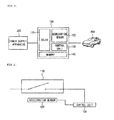
- Fig. 1 is a block diagram illustrating an electric charging apparatus in charging a vehicle according to an embodiment.
- the electric charging apparatus according to the embodiment is described in relation to Fig. 1 .
- the electric charging apparatus 100 may include a relay 110, an acceleration sensor 120, a control unit 130 and a memory 140.
- the elements shown in Fig. 1 are not necessities and the electric charging apparatus 100 may be implemented with more other elements or fewer elements.
- the electric charging apparatus 100 receives a power supply voltage from a power supply apparatus 200 and charges an electric vehicle 300.
- the electric vehicle 300 is exemplified herein, but the present invention is not limited thereto and the electric vehicle 300 may be replaced with an electrically rechargeable device.
- Fig. 2 is a view simply illustrating a relay, an acceleration sensor, and a control unit according to an embodiment.
- the relay, the acceleration sensor, and the control unit according to an embodiment are described in relation to Fig. 2 .
- the relay 110 receives a relay state changing control signal from the control unit 130 and controls a current flowing through the electric charging apparatus 100.
- the relay 110 may include one or more switches.
- the relay 100 may turn on the switch.
- the relay 100 may turn off the switch.
- a dynamic force component such as an acceleration of, a vibration of, or a shock on an object may be measured by processing an output signal of the acceleration sensor 120.
- the acceleration sensor 120 Since specifically sensing a moving state of the object, the acceleration sensor 120 is used for various transportation means, such as a vehicle, a train, a vessel, or an airplane, and a robot.
- the acceleration sensor 120 may sense a vibration of the relay 110 according to a state change of the switch of the relay 110.
- the acceleration sensor 120 senses the vibration of the relay 110 to generate an acceleration sensing signal.
- the control unit 130 controls an entire operation of the electric charging apparatus 100.
- the control unit 130 receives the acceleration sensing signal of the acceleration sensor 120 to diagnose failures in the electric charging apparatus 100.
- the control unit 120 controls a state change of the switch of the relay.
- the state change of the switch may represent a change from a turned-on state into a turned-off state or from a turned-off state into a turned-on state.
- the acceleration sensor 120 may be attached to a bottom end of the relay 100 and sense the vibration of the relay 110.
- a position of the acceleration sensor 120 is not limited thereto and may be positioned at a part at which the vibration of the relay 100 may be sensed.
- a method of diagnosing, by the control unit 130, failures in the electric charging apparatus 100 is as follows.
- the control unit 130 may analyze a waveform of the acceleration sensing signal from the acceleration sensor 120 and diagnose failures in the electric charging apparatus 100.
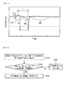
- Fig. 3 is a waveform diagram of the acceleration sensing signal according to the vibration of the relay according to an embodiment.
- the waveform of an acceleration sensing signal according to a vibration of the relay 110 sequentially includes three vibration periods of a small vibration period 410, a large vibration period 420, and a fine vibration period 430.
- the small vibration period 410 occurs rightly before a switch state of the relay 110 is changed.
- the switch of the relay 110 moves for a state change according to a pulse signal from the control unit 130. Due to this moving operation, the relay 110 vibrates in small amplitude.
- the large vibration period 420 occurs at a moment that the state of the switch of the relay 110 is changed.
- the switch of the relay 110 in the large vibration period 410 switches from an ON state into an OFF state or from an OFF state into an ON state.
- a physical force occurs according to a movement of the switch and, due to this force, the relay 100 vibrates larger than in the small vibration period 410.
- the fine vibration period 430 occurs after the state of the switch of the relay 110 is changed. In the fine vibration period 430, the relay 110 finely vibrates due to the physical force occurred in the large vibration period 420.
- the control unit 130 may detect a peak value A1 in the small vibration period 410, a peak value A2 in the large vibration period 420, or a time T taken from the peak value A1 in the small vibration period 410 to the peak value A2 in the large vibration period 420.
- the control unit 130 may compare current values of A1, A2, and T with normal ranges of A1, A2, and T.
- the normal range may represent ranges of A1, A2, and T when the electric charging device 100 normally operates, and be stored in the memory 140. According to the comparison result, when even any one value of the detected A1, A2, and T is out of the normal range, the control unit 130 may detect occurrence of failure of the relay 110. When the failure, for example, fusing of the switch of the relay 110 occurs due to overcurrent or other causes, the magnitude of A1 or A2 may be decreased or increased. In addition, the value of T may be decreased or increased.
- the memory 140 may store the peak value A1 in the small vibration period 410, the peak value A2 of the large vibration period 420, and a value of time T taken from the peak value A1 in the small vibration period 410 to the peak value A2 in the large vibration period 420.
- control unit 130 may stop operation of the electric charging apparatus 100 or notifying a user of the failure occurrence.
- control unit 130 may respectively compare current values of A1, A2, and T with normal ranges stored in the memory 140.
- the memory 140 may store a program for operation of the control unit 130 and temporarily store input/output data.
- the memory 140 may include at least one recording medium of a flash memory type, hard disk type, multimedia card micro type, or card type memory (for example, SD or XD memory), a Random Access Memory (RAM), a Static Random Access Memory (SRAM), a Read-Only Memory (ROM), an Electrically Erasable Programmable Read-Only Memory (EEPROM), a Programmable Read-Only Memory (PROM), a magnetic memory, a magnetic disk, or an optical disk.
- a flash memory type for example, SD or XD memory
- RAM Random Access Memory
- SRAM Static Random Access Memory
- ROM Read-Only Memory
- EEPROM Electrically Erasable Programmable Read-Only Memory
- PROM Programmable Read-Only Memory
- the memory 140 may store various numerical values according to an embodiment.
- Fig. 4 is a flowchart illustrating a failure determination method for an electric charging apparatus.
- the control unit 130 detects values of A1, A2, and T according to the vibration of the relay (operation S101).
- the control unit 130 compares the detected A1, A2, and T values with each normal range, respectively (operation S103).
- control unit 130 determines that the electric charging apparatus 100 operates normally (operation S105).
- control unit 130 determines that the electric charging apparatus 100 is in failure (operation S107).
- failures in an electric charging apparatus can be easily detected.
Landscapes
- Engineering & Computer Science (AREA)
- Power Engineering (AREA)
- Transportation (AREA)
- Mechanical Engineering (AREA)
- Life Sciences & Earth Sciences (AREA)
- Sustainable Development (AREA)
- Sustainable Energy (AREA)
- Charge And Discharge Circuits For Batteries Or The Like (AREA)
- Electric Propulsion And Braking For Vehicles (AREA)
Abstract
Description
- The present application claims priority under 35 U.S.C. 119 and 35 U.S.C. 365 to Korean Patent Application No.
10-2013-0053862 (filed on May 13, 2013 - The present disclosure relates to an electric charging apparatus and a failure determination method therefor, and more particularly, to an electric charging apparatus for a vehicle which detects a vibration of a relay to generate an acceleration sensing signal and receives the acceleration sensing signal to detect a failure in the electric charging apparatus, and a failure determination method therefor.
- As global environmental pollution is worsening, use of non-polluting energy is getting more important. Especially, air pollution problems in a metropolitan area are worsening day by day, and an exhaust gas is one of the main causes of them. Under such a situation, recently researches are being actively performed on commercializing a so-called electric vehicle using the electricity, which is nonpolluting energy, as a power source. The electric vehicle receives electric energy from the outside and charges a battery with it, and then uses a voltage charged in the battery to obtain power, which is mechanical energy, through a motor combined with wheels. That is, since the motor is driven by the voltage charged in the battery, the electric vehicle uses a large capacity rechargeable battery and includes an electric charging apparatus for charging the large capacity rechargeable battery.
- An electric charging apparatus is divided into a rapid charger and a slow charger. The rapid charger is installed at a place for rapidly charging a battery during driving like a gas station. Charging time thereof takes about 20 min. On the contrary, the slow charger is installed at a place, such as a parking lot or a shopping mall, where long time parking is expected. Charging time thereof takes about 5 hours.
- Such an electric charging apparatus includes a relay, and failures may occur in the relay such that the relay may be fused due to overcurrent or other causes during charging a charging target device.
- However, it is difficult that a typical electric charging apparatus may detect such failures.
- Embodiments provide an electric charging apparatus and a failure determination method therefor which can easily find failures in the electric charging apparatus.
- In one embodiment, an electric charging apparatus includes: a relay allowing a current to flow inside the electric charging apparatus by switching of a switch; an acceleration sensor detecting a vibration of the relay and generating an acceleration sensing signal; and a control unit analyzing a waveform of the acceleration sensing signal from the acceleration sensor and detecting failure of the electric charging apparatus, wherein the waveform of the acceleration sensing signal sequentially comprises a small vibration period, a large vibration period while a state of the switch is changed, and the control unit detects failure of the electric charging apparatus based on at least any one factor of a peak value in the small vibration period, a peak value in the large vibration period, and a time taken from the peak value in the small vibration period to the peak value in the large vibration period.
- In further another embodiment, a failure determination method for an electric charging apparatus, includes: flowing a current inside the electric charging apparatus by switching of a switch included in a relay; detecting, by an acceleration sensor, a vibration of the relay and generating an acceleration sensing signal; and analyzing a waveform of the acceleration sensing signal from the acceleration sensor and detecting failure in the electric charging apparatus, wherein the waveform of the acceleration sensing signal sequentially comprises a small vibration period, a large vibration period while a state of the switch is changed, and the detecting of the failure comprises detecting the failure of the electric charging apparatus based on at least any one factor of a peak value in the small vibration period, a peak value in the large vibration period, and a time taken from the peak value in the small vibration period to the peak value in the large vibration period.
- The acceleration sensor may be attached to the relay and detects the vibration of the relay.
- The failure determination method may further include storing normal ranges of the waveform factors in a memory when the relay operates normally.
- The detecting of the failure may include comparing at least any one factor of a current peak value in the small vibration period, a current peak value of the large vibration period in the large vibration period, and a current time taken from the peak value in the small vibration period to the peak value in the large vibration period with a corresponding normal range and detecting the failure of the electric charging apparatus when the factor is out of the normal range.
- The normal range may be at least any one of a normal range of a peak value in the small vibration period, a normal range of a peak value in the large vibration period, and a normal range of a time taken from the peak value in the small vibration period to the peak value in the large vibration period.
- The failure determination method may further include, when the failure in the electric charging apparatus is detected, notifying a user of the failure or stopping charging the electric charging apparatus.
- The details of one or more embodiments are set forth in the accompanying drawings and the description below. Other features will be apparent from the description and drawings, and from the claims.
-
-
Fig. 1 is a block diagram illustrating a battery charging apparatus in charging a vehicle according to an embodiment. -
Fig. 2 is a view simply illustrating a relay, an acceleration sensor, and a control unit according to an embodiment. -
Fig. 3 is a waveform diagram representing a vibration of a relay as a waveform according to an embodiment. -
Fig. 4 is a flow chart illustrating a failure determination method for an electric charging apparatus according to an embodiment. - Reference will now be made in detail to the embodiments of the present disclosure, examples of which are illustrated in the accompanying drawings. In the specification, descriptions or drawings on portions irrelative to the present invention will be omitted, or briefly described or drawn. Like reference numerals refer to like elements throughout.
- It will be further understood that the terms "comprises" and/or "comprising" used herein specify the presence of stated features or components, but do not preclude the presence or addition of one or more other features or components.
- It will be understood that when a part is referred to as being "connected" to another part, it can be "directly connected" to the other part or "electrically connected" to the other part with an intervening layer present between them.
- In the following description, usage of suffixes such as 'module' or 'unit' used for referring to elements is given merely to facilitate explanation of the present invention, without having any significant meaning by itself.
- An electric charging apparatus and an operation method therefor according to an embodiment will be described in detail with reference to the accompanying drawings. The invention may, however, be embodied in many different forms and should not be construed as being limited to the embodiments set forth herein; rather, that alternate embodiments included in other retrogressive inventions or falling within the spirit and scope of the present disclosure can easily be derived through adding, altering, and changing, and will fully convey the concept of the invention to those skilled in the art.
-
Fig. 1 is a block diagram illustrating an electric charging apparatus in charging a vehicle according to an embodiment. - The electric charging apparatus according to the embodiment is described in relation to
Fig. 1 . - The
electric charging apparatus 100 according to an embodiment may include arelay 110, anacceleration sensor 120, acontrol unit 130 and amemory 140. However, the elements shown inFig. 1 are not necessities and theelectric charging apparatus 100 may be implemented with more other elements or fewer elements. - The
electric charging apparatus 100 receives a power supply voltage from apower supply apparatus 200 and charges anelectric vehicle 300. Theelectric vehicle 300 is exemplified herein, but the present invention is not limited thereto and theelectric vehicle 300 may be replaced with an electrically rechargeable device. -
Fig. 2 is a view simply illustrating a relay, an acceleration sensor, and a control unit according to an embodiment. - The relay, the acceleration sensor, and the control unit according to an embodiment are described in relation to
Fig. 2 . - The
relay 110 receives a relay state changing control signal from thecontrol unit 130 and controls a current flowing through theelectric charging apparatus 100. - As shown in
Fig. 2 , therelay 110 may include one or more switches. When a value of the relay state changing control signal corresponds to a relay on, therelay 100 may turn on the switch. When the value of the relay state changing control signal corresponds to a relay off, therelay 100 may turn off the switch. - A dynamic force component, such as an acceleration of, a vibration of, or a shock on an object may be measured by processing an output signal of the
acceleration sensor 120. Since specifically sensing a moving state of the object, theacceleration sensor 120 is used for various transportation means, such as a vehicle, a train, a vessel, or an airplane, and a robot. Theacceleration sensor 120 may sense a vibration of therelay 110 according to a state change of the switch of therelay 110. Theacceleration sensor 120 senses the vibration of therelay 110 to generate an acceleration sensing signal. - The
control unit 130 controls an entire operation of theelectric charging apparatus 100. Thecontrol unit 130 receives the acceleration sensing signal of theacceleration sensor 120 to diagnose failures in theelectric charging apparatus 100. - The
control unit 120 according to an embodiment controls a state change of the switch of the relay. Here, the state change of the switch may represent a change from a turned-on state into a turned-off state or from a turned-off state into a turned-on state. - The
acceleration sensor 120 according to an embodiment may be attached to a bottom end of therelay 100 and sense the vibration of therelay 110. However, a position of theacceleration sensor 120 is not limited thereto and may be positioned at a part at which the vibration of therelay 100 may be sensed. - A method of diagnosing, by the
control unit 130, failures in theelectric charging apparatus 100 is as follows. Thecontrol unit 130 may analyze a waveform of the acceleration sensing signal from theacceleration sensor 120 and diagnose failures in theelectric charging apparatus 100. -
Fig. 3 is a waveform diagram of the acceleration sensing signal according to the vibration of the relay according to an embodiment. - Referring to
Fig. 3 , a waveform of an acceleration sensing signal according to the vibration of therelay 110 according to the switch on/off is described. - The waveform of an acceleration sensing signal according to a vibration of the
relay 110 sequentially includes three vibration periods of asmall vibration period 410, alarge vibration period 420, and afine vibration period 430. - The
small vibration period 410 occurs rightly before a switch state of therelay 110 is changed. In thesmall vibration period 410, the switch of therelay 110 moves for a state change according to a pulse signal from thecontrol unit 130. Due to this moving operation, therelay 110 vibrates in small amplitude. - The
large vibration period 420 occurs at a moment that the state of the switch of therelay 110 is changed. The switch of therelay 110 in thelarge vibration period 410 switches from an ON state into an OFF state or from an OFF state into an ON state. At this time, a physical force occurs according to a movement of the switch and, due to this force, therelay 100 vibrates larger than in thesmall vibration period 410. - The
fine vibration period 430 occurs after the state of the switch of therelay 110 is changed. In thefine vibration period 430, therelay 110 finely vibrates due to the physical force occurred in thelarge vibration period 420. - The
control unit 130 may detect a peak value A1 in thesmall vibration period 410, a peak value A2 in thelarge vibration period 420, or a time T taken from the peak value A1 in thesmall vibration period 410 to the peak value A2 in thelarge vibration period 420. - The
control unit 130 may compare current values of A1, A2, and T with normal ranges of A1, A2, and T. The normal range may represent ranges of A1, A2, and T when theelectric charging device 100 normally operates, and be stored in thememory 140. According to the comparison result, when even any one value of the detected A1, A2, and T is out of the normal range, thecontrol unit 130 may detect occurrence of failure of therelay 110. When the failure, for example, fusing of the switch of therelay 110 occurs due to overcurrent or other causes, the magnitude of A1 or A2 may be decreased or increased. In addition, the value of T may be decreased or increased. - According to an embodiment, the
memory 140 may store the peak value A1 in thesmall vibration period 410, the peak value A2 of thelarge vibration period 420, and a value of time T taken from the peak value A1 in thesmall vibration period 410 to the peak value A2 in thelarge vibration period 420. - When detecting occurrence of failure of the
relay 110, thecontrol unit 130 may stop operation of theelectric charging apparatus 100 or notifying a user of the failure occurrence. - According to an embodiment, the
control unit 130 may respectively compare current values of A1, A2, and T with normal ranges stored in thememory 140. - Referring to
Fig. 1 again, the electric charging apparatus is described. - The
memory 140 may store a program for operation of thecontrol unit 130 and temporarily store input/output data. - The
memory 140 may include at least one recording medium of a flash memory type, hard disk type, multimedia card micro type, or card type memory (for example, SD or XD memory), a Random Access Memory (RAM), a Static Random Access Memory (SRAM), a Read-Only Memory (ROM), an Electrically Erasable Programmable Read-Only Memory (EEPROM), a Programmable Read-Only Memory (PROM), a magnetic memory, a magnetic disk, or an optical disk. - The
memory 140 may store various numerical values according to an embodiment. -
Fig. 4 is a flowchart illustrating a failure determination method for an electric charging apparatus. - Referring to
Fig. 4 , the failure determination method for the electric charging apparatus is described. - The
control unit 130 detects values of A1, A2, and T according to the vibration of the relay (operation S101). - The
control unit 130 compares the detected A1, A2, and T values with each normal range, respectively (operation S103). - When the A1, A2, and T values are all in the normal ranges respectively, the
control unit 130 determines that theelectric charging apparatus 100 operates normally (operation S105). - When the A1, A2, and T values are not in the normal ranges respectively, the
control unit 130 determines that theelectric charging apparatus 100 is in failure (operation S107). - The above-described configuration and method of the above-described embodiments are not limitedly applied to the
electric charging apparatus 100. All of or a part of embodiments are selectively combined and configured to enable various modifications to be performed. - According to an embodiment, failures in an electric charging apparatus can be easily detected.
- Although embodiments have been described with reference to a number of illustrative embodiments thereof, it should be understood that numerous other modifications and embodiments can be devised by those skilled in the art that will fall within the spirit and scope of the principles of this disclosure. More particularly, various variations and modifications are possible in the component parts and/or arrangements of the subject combination arrangement within the scope of the disclosure, the drawings and the appended claims. In addition to variations and modifications in the component parts and/or arrangements, alternative uses will also be apparent to those skilled in the art.
Claims (12)
- An electric charging apparatus comprising:a relay allowing a current to flow inside the electric charging apparatus by switching of a switch;an acceleration sensor detecting a vibration of the relay and generating an acceleration sensing signal; anda control unit analyzing a waveform of the acceleration sensing signal from the acceleration sensor and detecting failure of the electric charging apparatus,wherein the waveform of the acceleration sensing signal sequentially comprises a small vibration period, a large vibration period while a state of the switch is changed, andthe control unit detects failure of the electric charging apparatus based on at least any one factor of a peak value in the small vibration period, a peak value in the large vibration period, and a time taken from the peak value in the small vibration period to the peak value in the large vibration period.
- The electric charging apparatus according to claim 1, wherein the acceleration sensor is attached to the relay and detects the vibration of the relay.
- The electric charging apparatus according to claim 1, further comprising a memory storing normal ranges of the factors of the waveform when the relay operates normally.
- The electric charging apparatus according to claim 3, wherein the control unit compares at least any one factor of a current peak value in the small vibration period, a current peak value in the large vibration period, and a current time taken from the peak value in the small vibration period to the peak value in the large vibration period with a corresponding normal range and detects the failure of the electric charging apparatus when the factor is out of the normal range.
- The electric charging apparatus according to claim 4, wherein the normal range is at least any one of a normal range of a peak value in the small vibration period, a normal range of a peak value in the large vibration period, and a normal range of a time taken from the peak value in the small vibration period to the peak value in the large vibration period.
- The electric charging apparatus according to claim 1, wherein, when detecting the failure in the electric charging apparatus, the control unit notifies a user of the failure or stops charging the electric charging apparatus.
- A failure determination method for an electric charging apparatus, comprising:flowing a current inside the electric charging apparatus by switching of a switch included in a relay;detecting, by an acceleration sensor, a vibration of the relay and generating an acceleration sensing signal; andanalyzing a waveform of the acceleration sensing signal from the acceleration sensor and detecting failure in the electric charging apparatus,wherein the waveform of the acceleration sensing signal sequentially comprises a small vibration period, a large vibration period while a state of the switch is changed, andthe detecting of the failure comprises detecting the failure of the electric charging apparatus based on at least any one factor of a peak value in the small vibration period, a peak value in the large vibration period, and a time taken from the peak value in the small vibration period to the peak value in the large vibration period.
- The failure determination method according to claim 7, wherein the acceleration sensor is attached to the relay and detects the vibration of the relay.
- The failure determination method according to claim 7, further comprising storing normal ranges of the waveform factors in a memory when the relay operates normally.
- The failure determination method according to claim 9, wherein the detecting of the failure comprises comparing at least any one factor of a current peak value in the small vibration period, a current peak value of the large vibration period in the large vibration period, and a current time taken from the peak value in the small vibration period to the peak value in the large vibration period with a corresponding normal range and detecting the failure of the electric charging apparatus when the factor is out of the normal range.
- The failure determination method according to claim 10, wherein the normal range is at least any one of a normal range of a peak value in the small vibration period, a normal range of a peak value in the large vibration period, and a normal range of a time taken from the peak value in the small vibration period to the peak value in the large vibration period.
- The failure determination method according to claim 7, further comprising, when the failure in the electric charging apparatus is detected, notifying a user of the failure or stopping charging the electric charging apparatus.
Applications Claiming Priority (1)
| Application Number | Priority Date | Filing Date | Title |
|---|---|---|---|
| KR1020130053862A KR101819252B1 (en) | 2013-05-13 | 2013-05-13 | Apparatus to charge battery voltage |
Publications (3)
| Publication Number | Publication Date |
|---|---|
| EP2810810A2 true EP2810810A2 (en) | 2014-12-10 |
| EP2810810A3 EP2810810A3 (en) | 2015-10-14 |
| EP2810810B1 EP2810810B1 (en) | 2016-12-07 |
Family
ID=50382330
Family Applications (1)
| Application Number | Title | Priority Date | Filing Date |
|---|---|---|---|
| EP14161921.3A Active EP2810810B1 (en) | 2013-05-13 | 2014-03-27 | Electric charging apparatus and failure determination method therefor |
Country Status (6)
| Country | Link |
|---|---|
| US (1) | US9269518B2 (en) |
| EP (1) | EP2810810B1 (en) |
| JP (1) | JP5894214B2 (en) |
| KR (1) | KR101819252B1 (en) |
| CN (1) | CN104158238B (en) |
| ES (1) | ES2618505T3 (en) |
Families Citing this family (5)
| Publication number | Priority date | Publication date | Assignee | Title |
|---|---|---|---|---|
| KR20160109410A (en) * | 2015-03-11 | 2016-09-21 | 엘에스산전 주식회사 | Recharging device for vehicle and method for protecting a circuit of the device |
| US20230186689A1 (en) * | 2021-12-14 | 2023-06-15 | GM Global Technology Operations LLC | Methods and mechanisms for crowd health monitoring charging port functionality |
| JP2023125707A (en) * | 2022-02-28 | 2023-09-07 | パナソニックIpマネジメント株式会社 | Judgment device, system, and judgment method |
| JP7380820B1 (en) | 2022-12-14 | 2023-11-15 | 三菱電機ビルソリューションズ株式会社 | Abnormality detection device |
| KR102708347B1 (en) * | 2024-02-27 | 2024-09-23 | 주식회사 에너솔루션 | Power cutoff system and method for electric vehicle charger with disaster safety function |
Family Cites Families (13)
| Publication number | Priority date | Publication date | Assignee | Title |
|---|---|---|---|---|
| JPH01232628A (en) * | 1988-03-14 | 1989-09-18 | Hitachi Ltd | Breaker opening/closing abnormality detection device |
| US5008516A (en) * | 1988-08-04 | 1991-04-16 | Whirlpool Corporation | Relay control method and apparatus for a domestic appliance |
| JP3166788B2 (en) | 1992-03-04 | 2001-05-14 | 出光興産株式会社 | Styrene resin composition |
| WO1993024845A1 (en) * | 1992-05-22 | 1993-12-09 | Siemens Aktiengesellschaft | Testing process for the quality control of electromagnetically actuated switching devices |
| JPH0670137A (en) | 1992-08-18 | 1994-03-11 | Canon Inc | Fax machine |
| JPH0670137U (en) * | 1993-03-10 | 1994-09-30 | 株式会社高岳製作所 | Monitoring device for disconnecting switch |
| US6412677B1 (en) * | 1998-09-16 | 2002-07-02 | Hoya Corporation | Cutting method for plate glass mother material |
| CN101286646B (en) | 2007-04-13 | 2011-10-26 | 宏碁股份有限公司 | Charging device for portable device |
| JP4894646B2 (en) * | 2007-06-15 | 2012-03-14 | トヨタ自動車株式会社 | Charging device and charging system |
| JP5172720B2 (en) * | 2009-01-09 | 2013-03-27 | プライムアースEvエナジー株式会社 | Relay inspection device and drive device |
| JP5240167B2 (en) * | 2009-11-11 | 2013-07-17 | 新日鐵住金株式会社 | Switch diagnosis method and switch diagnosis device |
| JP3166788U (en) * | 2011-01-07 | 2011-03-24 | 株式会社 アイチメンテナンス | Elevator diagnostic device |
| JP5787231B2 (en) * | 2012-06-11 | 2015-09-30 | 新日鐵住金株式会社 | Diagnosis method and apparatus for switch |
-
2013
- 2013-05-13 KR KR1020130053862A patent/KR101819252B1/en active Active
-
2014
- 2014-03-27 EP EP14161921.3A patent/EP2810810B1/en active Active
- 2014-03-27 ES ES14161921.3T patent/ES2618505T3/en active Active
- 2014-04-08 US US14/248,187 patent/US9269518B2/en active Active
- 2014-04-22 JP JP2014087844A patent/JP5894214B2/en active Active
- 2014-05-13 CN CN201410201360.8A patent/CN104158238B/en active Active
Non-Patent Citations (1)
| Title |
|---|
| None |
Also Published As
| Publication number | Publication date |
|---|---|
| JP5894214B2 (en) | 2016-03-23 |
| CN104158238B (en) | 2017-04-12 |
| CN104158238A (en) | 2014-11-19 |
| US9269518B2 (en) | 2016-02-23 |
| EP2810810A3 (en) | 2015-10-14 |
| KR101819252B1 (en) | 2018-01-16 |
| EP2810810B1 (en) | 2016-12-07 |
| JP2014223007A (en) | 2014-11-27 |
| ES2618505T3 (en) | 2017-06-21 |
| KR20140134118A (en) | 2014-11-21 |
| US20140334056A1 (en) | 2014-11-13 |
Similar Documents
| Publication | Publication Date | Title |
|---|---|---|
| US9269518B2 (en) | Electric charging apparatus and failure determination method therefor | |
| JP6201160B2 (en) | Power supply control device and relay abnormality detection method | |
| JP7248221B2 (en) | Earth leakage detection device, earth leakage detection method, and electric vehicle | |
| JP5373120B2 (en) | Abnormality diagnosis method and apparatus for battery pack current measuring unit | |
| EP2365605B1 (en) | Charging apparatus, program | |
| JP6206317B2 (en) | Power storage system | |
| KR101491366B1 (en) | Apparatus and method for managing a battery of the vehicle | |
| US11230310B2 (en) | Monitoring of a horizontal damping element for a rail vehicle | |
| CN102652265A (en) | Measuring isolated high voltage and detecting isolation breakdown with measures for self-detection of circuit faults | |
| JP2017123327A (en) | Battery control device and battery control system | |
| JP2009250796A (en) | Method of diagnosing deterioration of storage battery and diagnostic system | |
| JP2024026100A (en) | Battery condition prediction device and battery condition prediction method | |
| JP2020523582A (en) | Device and method for diagnosing watchdog timer | |
| EP4496170A1 (en) | Power supply system, electric moving body, charger, and energization confirmation method | |
| JP5230789B2 (en) | Battery system | |
| JP2018012398A (en) | Electric power storage apparatus | |
| CN109239511B (en) | Train, train power supply system and electric leakage detection positioning device and method thereof | |
| JP5938722B2 (en) | Insulation resistance drop detection device and insulation resistance drop detection method | |
| JP5561049B2 (en) | Battery voltage measuring device | |
| US20140358460A1 (en) | Electric vehicle and method for controlling same | |
| JP2013145735A (en) | Power storage system | |
| CN109245027B (en) | Train, train power supply system and its leakage detection and recovery device and method | |
| CN105990867A (en) | Device for detecting level of control pilot signal and charging control system having the same | |
| CN108698548B (en) | Charging rate monitoring device for in-vehicle power supply and in-vehicle power supply system | |
| KR20140093122A (en) | Electric vehicle and controlling method |
Legal Events
| Date | Code | Title | Description |
|---|---|---|---|
| PUAI | Public reference made under article 153(3) epc to a published international application that has entered the european phase |
Free format text: ORIGINAL CODE: 0009012 |
|
| 17P | Request for examination filed |
Effective date: 20140327 |
|
| AK | Designated contracting states |
Kind code of ref document: A2 Designated state(s): AL AT BE BG CH CY CZ DE DK EE ES FI FR GB GR HR HU IE IS IT LI LT LU LV MC MK MT NL NO PL PT RO RS SE SI SK SM TR |
|
| AX | Request for extension of the european patent |
Extension state: BA ME |
|
| PUAL | Search report despatched |
Free format text: ORIGINAL CODE: 0009013 |
|
| AK | Designated contracting states |
Kind code of ref document: A3 Designated state(s): AL AT BE BG CH CY CZ DE DK EE ES FI FR GB GR HR HU IE IS IT LI LT LU LV MC MK MT NL NO PL PT RO RS SE SI SK SM TR |
|
| AX | Request for extension of the european patent |
Extension state: BA ME |
|
| RIC1 | Information provided on ipc code assigned before grant |
Ipc: B60L 3/00 20060101AFI20150904BHEP Ipc: B60L 11/18 20060101ALI20150904BHEP Ipc: H01H 47/00 20060101ALI20150904BHEP |
|
| R17P | Request for examination filed (corrected) |
Effective date: 20160111 |
|
| RBV | Designated contracting states (corrected) |
Designated state(s): AL AT BE BG CH CY CZ DE DK EE ES FI FR GB GR HR HU IE IS IT LI LT LU LV MC MK MT NL NO PL PT RO RS SE SI SK SM TR |
|
| RIC1 | Information provided on ipc code assigned before grant |
Ipc: B60L 11/18 20060101ALI20160519BHEP Ipc: H01H 47/00 20060101ALI20160519BHEP Ipc: B60L 3/00 20060101AFI20160519BHEP |
|
| GRAP | Despatch of communication of intention to grant a patent |
Free format text: ORIGINAL CODE: EPIDOSNIGR1 |
|
| INTG | Intention to grant announced |
Effective date: 20160706 |
|
| GRAS | Grant fee paid |
Free format text: ORIGINAL CODE: EPIDOSNIGR3 |
|
| GRAA | (expected) grant |
Free format text: ORIGINAL CODE: 0009210 |
|
| AK | Designated contracting states |
Kind code of ref document: B1 Designated state(s): AL AT BE BG CH CY CZ DE DK EE ES FI FR GB GR HR HU IE IS IT LI LT LU LV MC MK MT NL NO PL PT RO RS SE SI SK SM TR |
|
| REG | Reference to a national code |
Ref country code: GB Ref legal event code: FG4D |
|
| REG | Reference to a national code |
Ref country code: CH Ref legal event code: EP Ref country code: AT Ref legal event code: REF Ref document number: 851387 Country of ref document: AT Kind code of ref document: T Effective date: 20161215 |
|
| REG | Reference to a national code |
Ref country code: IE Ref legal event code: FG4D |
|
| REG | Reference to a national code |
Ref country code: DE Ref legal event code: R096 Ref document number: 602014005274 Country of ref document: DE |
|
| REG | Reference to a national code |
Ref country code: FR Ref legal event code: PLFP Year of fee payment: 4 |
|
| PG25 | Lapsed in a contracting state [announced via postgrant information from national office to epo] |
Ref country code: LV Free format text: LAPSE BECAUSE OF FAILURE TO SUBMIT A TRANSLATION OF THE DESCRIPTION OR TO PAY THE FEE WITHIN THE PRESCRIBED TIME-LIMIT Effective date: 20161207 |
|
| REG | Reference to a national code |
Ref country code: LT Ref legal event code: MG4D |
|
| REG | Reference to a national code |
Ref country code: NL Ref legal event code: MP Effective date: 20161207 |
|
| PG25 | Lapsed in a contracting state [announced via postgrant information from national office to epo] |
Ref country code: SE Free format text: LAPSE BECAUSE OF FAILURE TO SUBMIT A TRANSLATION OF THE DESCRIPTION OR TO PAY THE FEE WITHIN THE PRESCRIBED TIME-LIMIT Effective date: 20161207 Ref country code: NO Free format text: LAPSE BECAUSE OF FAILURE TO SUBMIT A TRANSLATION OF THE DESCRIPTION OR TO PAY THE FEE WITHIN THE PRESCRIBED TIME-LIMIT Effective date: 20170307 Ref country code: LT Free format text: LAPSE BECAUSE OF FAILURE TO SUBMIT A TRANSLATION OF THE DESCRIPTION OR TO PAY THE FEE WITHIN THE PRESCRIBED TIME-LIMIT Effective date: 20161207 Ref country code: GR Free format text: LAPSE BECAUSE OF FAILURE TO SUBMIT A TRANSLATION OF THE DESCRIPTION OR TO PAY THE FEE WITHIN THE PRESCRIBED TIME-LIMIT Effective date: 20170308 |
|
| REG | Reference to a national code |
Ref country code: AT Ref legal event code: MK05 Ref document number: 851387 Country of ref document: AT Kind code of ref document: T Effective date: 20161207 |
|
| PG25 | Lapsed in a contracting state [announced via postgrant information from national office to epo] |
Ref country code: RS Free format text: LAPSE BECAUSE OF FAILURE TO SUBMIT A TRANSLATION OF THE DESCRIPTION OR TO PAY THE FEE WITHIN THE PRESCRIBED TIME-LIMIT Effective date: 20161207 Ref country code: HR Free format text: LAPSE BECAUSE OF FAILURE TO SUBMIT A TRANSLATION OF THE DESCRIPTION OR TO PAY THE FEE WITHIN THE PRESCRIBED TIME-LIMIT Effective date: 20161207 Ref country code: FI Free format text: LAPSE BECAUSE OF FAILURE TO SUBMIT A TRANSLATION OF THE DESCRIPTION OR TO PAY THE FEE WITHIN THE PRESCRIBED TIME-LIMIT Effective date: 20161207 |
|
| REG | Reference to a national code |
Ref country code: ES Ref legal event code: FG2A Ref document number: 2618505 Country of ref document: ES Kind code of ref document: T3 Effective date: 20170621 |
|
| PG25 | Lapsed in a contracting state [announced via postgrant information from national office to epo] |
Ref country code: NL Free format text: LAPSE BECAUSE OF FAILURE TO SUBMIT A TRANSLATION OF THE DESCRIPTION OR TO PAY THE FEE WITHIN THE PRESCRIBED TIME-LIMIT Effective date: 20161207 |
|
| PG25 | Lapsed in a contracting state [announced via postgrant information from national office to epo] |
Ref country code: RO Free format text: LAPSE BECAUSE OF FAILURE TO SUBMIT A TRANSLATION OF THE DESCRIPTION OR TO PAY THE FEE WITHIN THE PRESCRIBED TIME-LIMIT Effective date: 20161207 Ref country code: SK Free format text: LAPSE BECAUSE OF FAILURE TO SUBMIT A TRANSLATION OF THE DESCRIPTION OR TO PAY THE FEE WITHIN THE PRESCRIBED TIME-LIMIT Effective date: 20161207 Ref country code: CZ Free format text: LAPSE BECAUSE OF FAILURE TO SUBMIT A TRANSLATION OF THE DESCRIPTION OR TO PAY THE FEE WITHIN THE PRESCRIBED TIME-LIMIT Effective date: 20161207 Ref country code: EE Free format text: LAPSE BECAUSE OF FAILURE TO SUBMIT A TRANSLATION OF THE DESCRIPTION OR TO PAY THE FEE WITHIN THE PRESCRIBED TIME-LIMIT Effective date: 20161207 Ref country code: IS Free format text: LAPSE BECAUSE OF FAILURE TO SUBMIT A TRANSLATION OF THE DESCRIPTION OR TO PAY THE FEE WITHIN THE PRESCRIBED TIME-LIMIT Effective date: 20170407 |
|
| PG25 | Lapsed in a contracting state [announced via postgrant information from national office to epo] |
Ref country code: PT Free format text: LAPSE BECAUSE OF FAILURE TO SUBMIT A TRANSLATION OF THE DESCRIPTION OR TO PAY THE FEE WITHIN THE PRESCRIBED TIME-LIMIT Effective date: 20170407 Ref country code: BG Free format text: LAPSE BECAUSE OF FAILURE TO SUBMIT A TRANSLATION OF THE DESCRIPTION OR TO PAY THE FEE WITHIN THE PRESCRIBED TIME-LIMIT Effective date: 20170307 Ref country code: PL Free format text: LAPSE BECAUSE OF FAILURE TO SUBMIT A TRANSLATION OF THE DESCRIPTION OR TO PAY THE FEE WITHIN THE PRESCRIBED TIME-LIMIT Effective date: 20161207 Ref country code: BE Free format text: LAPSE BECAUSE OF FAILURE TO SUBMIT A TRANSLATION OF THE DESCRIPTION OR TO PAY THE FEE WITHIN THE PRESCRIBED TIME-LIMIT Effective date: 20161207 Ref country code: AT Free format text: LAPSE BECAUSE OF FAILURE TO SUBMIT A TRANSLATION OF THE DESCRIPTION OR TO PAY THE FEE WITHIN THE PRESCRIBED TIME-LIMIT Effective date: 20161207 Ref country code: SM Free format text: LAPSE BECAUSE OF FAILURE TO SUBMIT A TRANSLATION OF THE DESCRIPTION OR TO PAY THE FEE WITHIN THE PRESCRIBED TIME-LIMIT Effective date: 20161207 |
|
| REG | Reference to a national code |
Ref country code: DE Ref legal event code: R097 Ref document number: 602014005274 Country of ref document: DE |
|
| PLBE | No opposition filed within time limit |
Free format text: ORIGINAL CODE: 0009261 |
|
| STAA | Information on the status of an ep patent application or granted ep patent |
Free format text: STATUS: NO OPPOSITION FILED WITHIN TIME LIMIT |
|
| REG | Reference to a national code |
Ref country code: CH Ref legal event code: PL |
|
| 26N | No opposition filed |
Effective date: 20170908 |
|
| PG25 | Lapsed in a contracting state [announced via postgrant information from national office to epo] |
Ref country code: SI Free format text: LAPSE BECAUSE OF FAILURE TO SUBMIT A TRANSLATION OF THE DESCRIPTION OR TO PAY THE FEE WITHIN THE PRESCRIBED TIME-LIMIT Effective date: 20161207 Ref country code: DK Free format text: LAPSE BECAUSE OF FAILURE TO SUBMIT A TRANSLATION OF THE DESCRIPTION OR TO PAY THE FEE WITHIN THE PRESCRIBED TIME-LIMIT Effective date: 20161207 Ref country code: MC Free format text: LAPSE BECAUSE OF FAILURE TO SUBMIT A TRANSLATION OF THE DESCRIPTION OR TO PAY THE FEE WITHIN THE PRESCRIBED TIME-LIMIT Effective date: 20161207 |
|
| REG | Reference to a national code |
Ref country code: IE Ref legal event code: MM4A |
|
| REG | Reference to a national code |
Ref country code: FR Ref legal event code: PLFP Year of fee payment: 5 |
|
| PG25 | Lapsed in a contracting state [announced via postgrant information from national office to epo] |
Ref country code: LU Free format text: LAPSE BECAUSE OF NON-PAYMENT OF DUE FEES Effective date: 20170327 |
|
| PG25 | Lapsed in a contracting state [announced via postgrant information from national office to epo] |
Ref country code: LI Free format text: LAPSE BECAUSE OF NON-PAYMENT OF DUE FEES Effective date: 20170331 Ref country code: IE Free format text: LAPSE BECAUSE OF NON-PAYMENT OF DUE FEES Effective date: 20170327 Ref country code: CH Free format text: LAPSE BECAUSE OF NON-PAYMENT OF DUE FEES Effective date: 20170331 |
|
| PG25 | Lapsed in a contracting state [announced via postgrant information from national office to epo] |
Ref country code: MT Free format text: LAPSE BECAUSE OF NON-PAYMENT OF DUE FEES Effective date: 20170327 |
|
| PG25 | Lapsed in a contracting state [announced via postgrant information from national office to epo] |
Ref country code: HU Free format text: LAPSE BECAUSE OF FAILURE TO SUBMIT A TRANSLATION OF THE DESCRIPTION OR TO PAY THE FEE WITHIN THE PRESCRIBED TIME-LIMIT; INVALID AB INITIO Effective date: 20140327 |
|
| PG25 | Lapsed in a contracting state [announced via postgrant information from national office to epo] |
Ref country code: CY Free format text: LAPSE BECAUSE OF FAILURE TO SUBMIT A TRANSLATION OF THE DESCRIPTION OR TO PAY THE FEE WITHIN THE PRESCRIBED TIME-LIMIT Effective date: 20161207 |
|
| PG25 | Lapsed in a contracting state [announced via postgrant information from national office to epo] |
Ref country code: MK Free format text: LAPSE BECAUSE OF FAILURE TO SUBMIT A TRANSLATION OF THE DESCRIPTION OR TO PAY THE FEE WITHIN THE PRESCRIBED TIME-LIMIT Effective date: 20161207 |
|
| PG25 | Lapsed in a contracting state [announced via postgrant information from national office to epo] |
Ref country code: TR Free format text: LAPSE BECAUSE OF FAILURE TO SUBMIT A TRANSLATION OF THE DESCRIPTION OR TO PAY THE FEE WITHIN THE PRESCRIBED TIME-LIMIT Effective date: 20161207 |
|
| PG25 | Lapsed in a contracting state [announced via postgrant information from national office to epo] |
Ref country code: AL Free format text: LAPSE BECAUSE OF FAILURE TO SUBMIT A TRANSLATION OF THE DESCRIPTION OR TO PAY THE FEE WITHIN THE PRESCRIBED TIME-LIMIT Effective date: 20161207 |
|
| P01 | Opt-out of the competence of the unified patent court (upc) registered |
Effective date: 20230625 |
|
| PGFP | Annual fee paid to national office [announced via postgrant information from national office to epo] |
Ref country code: ES Payment date: 20250408 Year of fee payment: 12 |
|
| PGFP | Annual fee paid to national office [announced via postgrant information from national office to epo] |
Ref country code: FR Payment date: 20251209 Year of fee payment: 13 |
|
| PGFP | Annual fee paid to national office [announced via postgrant information from national office to epo] |
Ref country code: GB Payment date: 20260108 Year of fee payment: 13 |
|
| PGFP | Annual fee paid to national office [announced via postgrant information from national office to epo] |
Ref country code: DE Payment date: 20251208 Year of fee payment: 13 |
|
| PGFP | Annual fee paid to national office [announced via postgrant information from national office to epo] |
Ref country code: IT Payment date: 20251209 Year of fee payment: 13 |