EP2810606A1 - Sleeve clamp - Google Patents
Sleeve clamp Download PDFInfo
- Publication number
- EP2810606A1 EP2810606A1 EP13171062.6A EP13171062A EP2810606A1 EP 2810606 A1 EP2810606 A1 EP 2810606A1 EP 13171062 A EP13171062 A EP 13171062A EP 2810606 A1 EP2810606 A1 EP 2810606A1
- Authority
- EP
- European Patent Office
- Prior art keywords
- sleeve
- clamping element
- bore
- push button
- sleeve clamp
- Prior art date
- Legal status (The legal status is an assumption and is not a legal conclusion. Google has not performed a legal analysis and makes no representation as to the accuracy of the status listed.)
- Granted
Links
Images

Classifications
-
- A—HUMAN NECESSITIES
- A61—MEDICAL OR VETERINARY SCIENCE; HYGIENE
- A61B—DIAGNOSIS; SURGERY; IDENTIFICATION
- A61B17/00—Surgical instruments, devices or methods
- A61B17/16—Instruments for performing osteoclasis; Drills or chisels for bones; Trepans
- A61B17/17—Guides or aligning means for drills, mills, pins or wires
-
- A—HUMAN NECESSITIES
- A61—MEDICAL OR VETERINARY SCIENCE; HYGIENE
- A61B—DIAGNOSIS; SURGERY; IDENTIFICATION
- A61B17/00—Surgical instruments, devices or methods
- A61B17/56—Surgical instruments or methods for treatment of bones or joints; Devices specially adapted therefor
- A61B17/58—Surgical instruments or methods for treatment of bones or joints; Devices specially adapted therefor for osteosynthesis, e.g. bone plates, screws or setting implements
- A61B17/88—Osteosynthesis instruments; Methods or means for implanting or extracting internal or external fixation devices
-
- A—HUMAN NECESSITIES
- A61—MEDICAL OR VETERINARY SCIENCE; HYGIENE
- A61B—DIAGNOSIS; SURGERY; IDENTIFICATION
- A61B17/00—Surgical instruments, devices or methods
- A61B17/16—Instruments for performing osteoclasis; Drills or chisels for bones; Trepans
- A61B17/17—Guides or aligning means for drills, mills, pins or wires
- A61B17/1725—Guides or aligning means for drills, mills, pins or wires for applying transverse screws or pins through intramedullary nails or pins
-
- A—HUMAN NECESSITIES
- A61—MEDICAL OR VETERINARY SCIENCE; HYGIENE
- A61B—DIAGNOSIS; SURGERY; IDENTIFICATION
- A61B17/00—Surgical instruments, devices or methods
- A61B17/56—Surgical instruments or methods for treatment of bones or joints; Devices specially adapted therefor
- A61B17/58—Surgical instruments or methods for treatment of bones or joints; Devices specially adapted therefor for osteosynthesis, e.g. bone plates, screws or setting implements
- A61B17/88—Osteosynthesis instruments; Methods or means for implanting or extracting internal or external fixation devices
- A61B17/90—Guides therefor
-
- A—HUMAN NECESSITIES
- A61—MEDICAL OR VETERINARY SCIENCE; HYGIENE
- A61B—DIAGNOSIS; SURGERY; IDENTIFICATION
- A61B17/00—Surgical instruments, devices or methods
- A61B17/16—Instruments for performing osteoclasis; Drills or chisels for bones; Trepans
- A61B17/17—Guides or aligning means for drills, mills, pins or wires
- A61B17/1728—Guides or aligning means for drills, mills, pins or wires for holes for bone plates or plate screws
-
- A—HUMAN NECESSITIES
- A61—MEDICAL OR VETERINARY SCIENCE; HYGIENE
- A61B—DIAGNOSIS; SURGERY; IDENTIFICATION
- A61B17/00—Surgical instruments, devices or methods
- A61B2017/0046—Surgical instruments, devices or methods with a releasable handle; with handle and operating part separable
- A61B2017/00469—Surgical instruments, devices or methods with a releasable handle; with handle and operating part separable for insertion of instruments, e.g. guide wire, optical fibre
-
- A—HUMAN NECESSITIES
- A61—MEDICAL OR VETERINARY SCIENCE; HYGIENE
- A61B—DIAGNOSIS; SURGERY; IDENTIFICATION
- A61B17/00—Surgical instruments, devices or methods
- A61B17/34—Trocars; Puncturing needles
- A61B2017/347—Locking means, e.g. for locking instrument in cannula
-
- A—HUMAN NECESSITIES
- A61—MEDICAL OR VETERINARY SCIENCE; HYGIENE
- A61B—DIAGNOSIS; SURGERY; IDENTIFICATION
- A61B17/00—Surgical instruments, devices or methods
- A61B17/34—Trocars; Puncturing needles
- A61B2017/348—Means for supporting the trocar against the body or retaining the trocar inside the body
- A61B2017/3492—Means for supporting the trocar against the body or retaining the trocar inside the body against the outside of the body
Definitions
- the invention relates to a device for holding a sleeve.
- the invention relates to a sleeve clamp.
- a sleeve may be utilized for leading, for example, a screw along a predetermined path.
- a tissue protection sleeve may be utilized to hold soft tissue aside when inserting a bone screw into a bone, for example so as to fix a fracture of the bone.
- the sleeve may facilitate an insertion of an instrument like a drill for drilling a bore, or a measuring instrument for determining an appropriate length of a screw to be inserted.
- the sleeve may be displaced by soft tissue structures surrounding a bone so that a screw insertion may be affected.
- EP 2 082 698 describes a clamp for a Kirschner wire.
- a Kirschner wire received in a sleeve is laterally pressed against an edge of the sleeve so as to hold the Kirschner wire in place.
- the Kirschner wire will tilt in the sleeve, i.e. the wire axis will be inclined relative to the sleeve axis.
- EP 1 415 599 as well as US 6 039 739 disclose a targeting device with a targeting arm, the targeting arm including a solid portion and an elastic portion.
- the elastic portion is separated from the solid portion by a slit.
- a through bore for receiving a wire or a sleeve is formed through both the solid portion and the elastic portion.
- the elastic portion can be used to fix a position of the wire or sleeve when being inserted in the through bore.
- US 2004/0059329 describes a resiliently deflectable lever which may cooperate with a sleeve which is guided through a transverse bore in a targeting arm portion, in a clamping manner when the lever is in a relaxed or released condition.
- An object may be defined as providing a device for easily and firmly holding an elongated element like a wire or a sleeve, without affecting a position and orientation of said element.
- a sleeve clamp comprises a body with a through bore for receiving a sleeve, and a clamping element.
- the clamping element includes a clamping edge and may be arranged at the body so as to be movable between two positions, i.e. a neutral position and a deflected position.
- the clamping edge In the neural position, the clamping edge protrudes laterally into a lumen which is occupied by the sleeve when the sleeve is received in the through bore.
- the clamping element In the deflected position, the clamping element may be elastically deformed and the clamping edge does not protrude into the lumen which is occupied by the sleeve when the sleeve is received in the through bore.
- a clamping element is provided at the body of the sleeve clamp, which clamping element protrudes into a free lumen, for example a through bore, as long as no sleeve is inserted into the lumen.
- the clamping element will be displaced out of the lumen as soon as a sleeve has been inserted into said lumen.
- the clamping element may be elastically deformable resulting in a restoring force which may press a clamping edge of the clamping element against the outer surface of the sleeve.
- a sleeve may be inserted against the restoring force of the clamping element, and pushed through the through bore in the body of the sleeve clamp. The pressing of the clamping edge against the sleeve holds the sleeve in position.
- the deflection of the clamping element further provides an axial force component which prevents an axial movement of the sleeve, in particular in a direction opposite to the sleeve inserting direction, even against any forces acting on the sleeve.
- the clamping element may be formed as a leaf spring. According to another embodiment, the clamping element may extend substantially perpendicular to a longitudinal axis of the through bore in which the sleeve may be received.
- the clamping element may be a separate element which is attached to the body of the sleeve clamp, for example by means of a screw or pin, by use of an adhesive, or by welding.
- the clamping element may be integrally formed with the body.
- the clamping edge may be curved like a section of an outer circumference of the sleeve.
- a line contact of the clamping element at the outer circumferential surface of the sleeve may be achieved.
- the sleeve clamp may comprise a push button for manually operating, for example deflecting the clamping element.
- the clamping element may be operated so as to release a sleeve or so as to completely open the lumen for receiving a sleeve without hindering forces.
- the clamping element may be arranged within the body and the body may further comprise an opening in which the push button may be arranged.
- the push button may also protrude through and out of the opening.
- the clamping element may comprise a base portion at which the clamping element is attached to the body, a free end portion including the clamping edge and a middle portion, wherein the push button may be attached to any one of these portions.
- the push button may be attached to the middle portion of the clamping element.
- the push button may be integrally formed with the clamping element.
- a top surface of the push button may be substantially at the same level as an outer surface of the body when the clamping element is in the deflected position. It is noted that 'substantially at the same level' should be understood as being substantially in one plane with a certain deviation. For example, the deviation may be in a range up to 30 percent, in particular 15 percent of the path length of the movement of the push button between the neutral position of the clamping element and the deflected position of the clamping element.
- the opening in the body may be only slightly larger than the width of the push button.
- a finger may come in contact with the outer surface of the body when pressing the push button to the position in which the clamping element is in the deflected position. As it would be difficult to further move the push button and thus the clamping element, an over-deflection of the clamping element may be prevented.
- the sleeve clamp as described above may be formed as a part of a targeting device for aligning a sleeve for an insertion of a bone screw with a locking hole in a bone nail for receiving the screw.
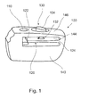
- FIG. 1 is an isometric illustration of an embodiment of a sleeve clamp 100.
- the sleeve clamp 100 comprises a body 140, a through bore 110, a clamping element 120 and a push button 130.
- the clamping element 120 is integrally formed with the body 140, with a transition at a base 124 of the clamping element. Furthermore, the clamping element extends from the base 124 substantially along a plane in a direction to and into the through bore 110, with the front end of the clamping element including a clamping edge 122, protruding into the lumen of the through bore.
- the clamping element 120 is arranged within a space formed by a lateral recess 144 in body 140, wherein the lateral recess intersects the through bore 110.
- the clamping element 120 is generally perpendicular to axis 112.
- the push button 130 is attached to the clamping element.
- the push button is integrally formed with the clamping element, with a base 132 at the clamping element and a top surface 134 protruding out of an opening in the body 140.
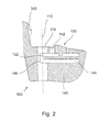
- the lateral recess 144, the opening 142 and the position of the clamping edge 122 is shown more clearly.
- the lateral recess 144 intersects the through bore 110, thus generating visible edges 146 in the surface of the through bore 110.
- the push button 130 is arranged in the opening 142.
- the clamping edge 122 protrudes into the lumen of the through bore, i.e. beyond the surface of the through bore 110.
- a longitudinal axis 112 of the through bore 110 is drawn in so that it can be seen that the clamping element 120 extends substantially perpendicular to this axis 112.
- the portion 300 extending away from the body 140 may be a part of a targeting device.
- clamping element 120 While the clamping element 120 is in the neutral position shown in figures 1 and 2 , the clamping element 120 is in a deflected position shown in figure 3 .
- a sleeve 200 is inserted into the through bore of the sleeve clamp 100.
- a shaft 210 of the sleeve 200 has a diameter which fits to a diameter of the trough bore so that any lateral movement or tilting of the sleeve within the through bore of the sleeve clamp can be prevented, i.e. the longitudinal axis 230 of the sleeve is congruent or coaxial with the axis 112 of the through bore.
- the front end of the sleeve shaft comes firstly in contact with the end of the clamping element 120 including the clamping edge 122 and then presses the same out of the lumen of the through bore by deflecting the clamping element.
- the clamping element 120 When the clamping element 120 is deflected it develops a spring force acting towards the lumen of the through bore 110. This force causes edge 122 of clamping element 120 to engage the outer surface of sleeve 200 and automatically hold it in place in bore 110.
- the top surface 134 of the push button 130 is substantially at or slightly above the level of the outer surface 146 of the body surrounding the opening 142.
- the double-arrow in figure 3 indicates the deflection movement of the clamping element 120, which movement is substantially parallel to the axis 230 of the sleeve, i.e. the deflection movement is in a plane together with the sleeve axis 230.
Landscapes
- Health & Medical Sciences (AREA)
- Surgery (AREA)
- Life Sciences & Earth Sciences (AREA)
- Orthopedic Medicine & Surgery (AREA)
- Biomedical Technology (AREA)
- Public Health (AREA)
- Veterinary Medicine (AREA)
- Engineering & Computer Science (AREA)
- Nuclear Medicine, Radiotherapy & Molecular Imaging (AREA)
- Heart & Thoracic Surgery (AREA)
- Medical Informatics (AREA)
- Molecular Biology (AREA)
- Animal Behavior & Ethology (AREA)
- General Health & Medical Sciences (AREA)
- Dentistry (AREA)
- Oral & Maxillofacial Surgery (AREA)
- Surgical Instruments (AREA)
- Insertion Pins And Rivets (AREA)
- Gripping On Spindles (AREA)
Abstract
Description
- The invention relates to a device for holding a sleeve. In particular, the invention relates to a sleeve clamp.
- A sleeve may be utilized for leading, for example, a screw along a predetermined path. In particular, a tissue protection sleeve may be utilized to hold soft tissue aside when inserting a bone screw into a bone, for example so as to fix a fracture of the bone.
- Previous to the insertion of a screw, the sleeve may facilitate an insertion of an instrument like a drill for drilling a bore, or a measuring instrument for determining an appropriate length of a screw to be inserted.
- However, the sleeve may be displaced by soft tissue structures surrounding a bone so that a screw insertion may be affected.
-
EP 2 082 698 describes a clamp for a Kirschner wire. A Kirschner wire received in a sleeve is laterally pressed against an edge of the sleeve so as to hold the Kirschner wire in place. However, the Kirschner wire will tilt in the sleeve, i.e. the wire axis will be inclined relative to the sleeve axis. -
EP 1 415 599 as well asUS 6 039 739 disclose a targeting device with a targeting arm, the targeting arm including a solid portion and an elastic portion. The elastic portion is separated from the solid portion by a slit. A through bore for receiving a wire or a sleeve is formed through both the solid portion and the elastic portion. The elastic portion can be used to fix a position of the wire or sleeve when being inserted in the through bore. -
US 2004/0059329 describes a resiliently deflectable lever which may cooperate with a sleeve which is guided through a transverse bore in a targeting arm portion, in a clamping manner when the lever is in a relaxed or released condition. - An object may be defined as providing a device for easily and firmly holding an elongated element like a wire or a sleeve, without affecting a position and orientation of said element.
- This is achieved by the subject-matter of the independent claim. Further embodiments are described in the dependent claims.
- In general, a sleeve clamp comprises a body with a through bore for receiving a sleeve, and a clamping element. The clamping element includes a clamping edge and may be arranged at the body so as to be movable between two positions, i.e. a neutral position and a deflected position. In the neural position, the clamping edge protrudes laterally into a lumen which is occupied by the sleeve when the sleeve is received in the through bore. In the deflected position, the clamping element may be elastically deformed and the clamping edge does not protrude into the lumen which is occupied by the sleeve when the sleeve is received in the through bore.
- In other words, a clamping element is provided at the body of the sleeve clamp, which clamping element protrudes into a free lumen, for example a through bore, as long as no sleeve is inserted into the lumen. The clamping element will be displaced out of the lumen as soon as a sleeve has been inserted into said lumen.
- According to an embodiment, the clamping element may be elastically deformable resulting in a restoring force which may press a clamping edge of the clamping element against the outer surface of the sleeve. Furthermore, a sleeve may be inserted against the restoring force of the clamping element, and pushed through the through bore in the body of the sleeve clamp. The pressing of the clamping edge against the sleeve holds the sleeve in position. The deflection of the clamping element further provides an axial force component which prevents an axial movement of the sleeve, in particular in a direction opposite to the sleeve inserting direction, even against any forces acting on the sleeve.
- According to an embodiment, the clamping element may be formed as a leaf spring. According to another embodiment, the clamping element may extend substantially perpendicular to a longitudinal axis of the through bore in which the sleeve may be received.
- It will be appreciated that the clamping element may be a separate element which is attached to the body of the sleeve clamp, for example by means of a screw or pin, by use of an adhesive, or by welding. According to one embodiment, the clamping element may be integrally formed with the body.
- So as to achieve a better holding effect, the clamping edge may be curved like a section of an outer circumference of the sleeve. Thus, a line contact of the clamping element at the outer circumferential surface of the sleeve may be achieved.
- According to a further embodiment, the sleeve clamp may comprise a push button for manually operating, for example deflecting the clamping element. Thus, the clamping element may be operated so as to release a sleeve or so as to completely open the lumen for receiving a sleeve without hindering forces.
- According to an embodiment, the clamping element may be arranged within the body and the body may further comprise an opening in which the push button may be arranged. The push button may also protrude through and out of the opening.
- The clamping element may comprise a base portion at which the clamping element is attached to the body, a free end portion including the clamping edge and a middle portion, wherein the push button may be attached to any one of these portions. In particular, the push button may be attached to the middle portion of the clamping element.
- As one possibility to attach the push button to the clamping element, the push button may be integrally formed with the clamping element.
- According to an embodiment, a top surface of the push button may be substantially at the same level as an outer surface of the body when the clamping element is in the deflected position. It is noted that 'substantially at the same level' should be understood as being substantially in one plane with a certain deviation. For example, the deviation may be in a range up to 30 percent, in particular 15 percent of the path length of the movement of the push button between the neutral position of the clamping element and the deflected position of the clamping element.
- According to an embodiment, the opening in the body may be only slightly larger than the width of the push button. In such a case, a finger may come in contact with the outer surface of the body when pressing the push button to the position in which the clamping element is in the deflected position. As it would be difficult to further move the push button and thus the clamping element, an over-deflection of the clamping element may be prevented.
- According to an embodiment, the sleeve clamp as described above may be formed as a part of a targeting device for aligning a sleeve for an insertion of a bone screw with a locking hole in a bone nail for receiving the screw.
- It has to be noted that a person skilled in the art will gather from the above and the following description that, unless otherwise notified, in addition to any combination of features belonging to one embodiment, also any combination of features relating to another embodiment is considered to be disclosed with this application.
- These and other objects, features and advantages of the exemplary embodiments of the present invention will become apparent upon reading the following detailed description of exemplary embodiments, when taken in conjunction with the appended claims.
- The invention will now be detailed by way of an exemplary embodiment with reference to the attached drawings.
-
Figure 1 is an isometric illustration of an embodiment of a sleeve clamp. -
Figure 2 is a section view of the sleeve clamp offigure 1 with the clamping element in a neutral position. -
Figure 3 is a section view of the sleeve clamp offigure 1 together with a sleeve, with the clamping element in a deflected position. - It is noted that the illustration in the drawings is only schematically and not to scale. Throughout the drawings, the same reference numerals and characters, unless otherwise stated, are used to denote like features, elements, components, or portions of the illustrated embodiments. Moreover, while the present invention will now be described in detail with reference to the figures, it is done so in connection with the illustrative embodiments and is not limited by the particular embodiments illustrated in the figures, as defined by the appended claims.
-
Figure 1 is an isometric illustration of an embodiment of asleeve clamp 100. Thesleeve clamp 100 comprises abody 140, a throughbore 110, aclamping element 120 and apush button 130. - The
clamping element 120 is integrally formed with thebody 140, with a transition at abase 124 of the clamping element. Furthermore, the clamping element extends from thebase 124 substantially along a plane in a direction to and into the throughbore 110, with the front end of the clamping element including aclamping edge 122, protruding into the lumen of the through bore. Here, the clampingelement 120 is arranged within a space formed by alateral recess 144 inbody 140, wherein the lateral recess intersects the throughbore 110. The clampingelement 120 is generally perpendicular toaxis 112. - At a middle portion of the
clamping element 120, thepush button 130 is attached to the clamping element. In particular, the push button is integrally formed with the clamping element, with a base 132 at the clamping element and atop surface 134 protruding out of an opening in thebody 140. - In the section view of
figure 2 , thelateral recess 144, theopening 142 and the position of the clampingedge 122 is shown more clearly. Thelateral recess 144 intersects the throughbore 110, thus generatingvisible edges 146 in the surface of the throughbore 110. Thepush button 130 is arranged in theopening 142. The clampingedge 122 protrudes into the lumen of the through bore, i.e. beyond the surface of the throughbore 110. Further, alongitudinal axis 112 of the throughbore 110 is drawn in so that it can be seen that the clampingelement 120 extends substantially perpendicular to thisaxis 112. - The
portion 300 extending away from thebody 140 may be a part of a targeting device. - While the clamping
element 120 is in the neutral position shown infigures 1 and2 , the clampingelement 120 is in a deflected position shown infigure 3 . - In
figure 3 , asleeve 200 is inserted into the through bore of thesleeve clamp 100. Ashaft 210 of thesleeve 200 has a diameter which fits to a diameter of the trough bore so that any lateral movement or tilting of the sleeve within the through bore of the sleeve clamp can be prevented, i.e. thelongitudinal axis 230 of the sleeve is congruent or coaxial with theaxis 112 of the through bore. When inserting thesleeve 200 into the through bore, starting with the front end (not shown) of thesleeve shaft 210, the front end of the sleeve shaft comes firstly in contact with the end of theclamping element 120 including theclamping edge 122 and then presses the same out of the lumen of the through bore by deflecting the clamping element. When theclamping element 120 is deflected it develops a spring force acting towards the lumen of the throughbore 110. This force causesedge 122 of clampingelement 120 to engage the outer surface ofsleeve 200 and automatically hold it in place inbore 110. - With the clamping element in the deflected position, the
top surface 134 of thepush button 130 is substantially at or slightly above the level of theouter surface 146 of the body surrounding theopening 142. - The double-arrow in
figure 3 indicates the deflection movement of theclamping element 120, which movement is substantially parallel to theaxis 230 of the sleeve, i.e. the deflection movement is in a plane together with thesleeve axis 230. By further deflecting theclamping element 120 by furtherdepressing push button 130, the clampingedge 122 comes out of contact with thesleeve shaft 210 so that the sleeve is released and may be pulled back and out of through bore. Oncesleeve 200 has been removed,push button 130 is released allowing clampingelement 120 to return to its neutral position. - While the invention has been illustrated and described in detail in the drawings and foregoing description, such illustration and description are to be considered illustrative or exemplary and not restrictive. The invention is not limited to the disclosed embodiments. Other variations to the disclosed embodiments can be understood and effected by those skilled in the art in practising the claimed invention, from a study of the drawings, the disclosure, and the appended claims.
- In the claims, the word "comprising" does not exclude other elements, and the indefinite article "a" or "an" does not exclude a plurality.
- The mere fact that the certain measures are recited in mutually different dependent claims does not indicate that a combination of these measures cannot be used to advantage. Any reference signs in the claims should not be construed as limiting the scope.
-
- 100
- sleeve clamp
- 110
- through bore
- 112
- axis of through bore
- 120
- clamping element
- 122
- clamping edge
- 124
- base of clamping element
- 130
- push button
- 132
- base of push button
- 134
- top surface of push button
- 140
- body
- 142
- opening
- 144
- recess
- 146
- outer surface of body
- 200
- sleeve
- 210
- sleeve shaft
- 220
- sleeve head
- 230
- axis of sleeve
- 300
- targeting device
Claims (12)
- A sleeve clamp (100) comprising
a body (140) with a through bore (110) for receiving a sleeve (200), and
a clamping element (120) having a clamping edge (122),
wherein the clamping element is arranged at the body so as to be movable between a neutral position in which the clamping edge protrudes laterally into a lumen which is occupied by the sleeve when the sleeve is received in the through bore, and a deflected position in which the clamping element is elastically deformed and in which the clamping edge does not protrude into the lumen. - The sleeve clamp of claim 1, wherein the clamping element (120) is formed as a leaf spring.
- The sleeve clamp of any one of claims 1 and 2, wherein the through bore (110) includes a longitudinal axis (112) and wherein the clamping element (120) extends substantially perpendicular to the axis of the through bore.
- The sleeve clamp of any one of claims 1 to 3, wherein the clamping element (120) is integrally formed with the body (140).
- The sleeve clamp of any one of claims 1 to 4, wherein the clamping edge (122) is curved so as to fit to a section of an outer circumference of the sleeve (200).
- The sleeve clamp of any one of claims 1 to 5, further comprising a push button (130) for manually deflecting the clamping element (120).
- The sleeve clamp of claim 6, wherein the clamping element (120) is arranged in the body (140) and the body further comprises an opening (142), wherein the push button is arranged in the opening.
- The sleeve clamp of claim 7, wherein the push button (130) protrudes through and out of the opening (142).
- The sleeve clamp of any one of claims 6 to 8, wherein the clamping element (120) comprises a base portion (124) at which the clamping element is attached to the body (140), a free end portion including the clamping edge (122) and a middle portion, wherein the push button (130) is attached to the middle portion of the clamping element.
- The sleeve clamp of claim 9, wherein the push button (130) is integrally formed with the clamping element (120).
- The sleeve clamp of any one of claims 6 to 10, wherein the push button (130) includes a top surface (134) and the body (140) includes an outer surface (146) surrounding the opening (142), and wherein the top surface of the push button is substantially at the same level as the outer surface of the body when the clamping element (120) is in the deflected position.
- The sleeve clamp of any one of the preceding claims, wherein the sleeve clamp (100) if formed as a part of a targeting device (300) for aligning a sleeve for an insertion of a bone screw with a locking hole in a bone nail for receiving the screw.
Priority Applications (7)
| Application Number | Priority Date | Filing Date | Title |
|---|---|---|---|
| ES13171062.6T ES2614991T3 (en) | 2013-06-07 | 2013-06-07 | Sleeve flange |
| EP13171062.6A EP2810606B1 (en) | 2013-06-07 | 2013-06-07 | Sleeve clamp |
| CA2853260A CA2853260C (en) | 2013-06-07 | 2014-06-02 | Sleeve clamp |
| AU2014203007A AU2014203007B2 (en) | 2013-06-07 | 2014-06-03 | Sleeve clamp |
| CN201410244788.0A CN104224304B (en) | 2013-06-07 | 2014-06-04 | sleeve clamp |
| US14/296,972 US9724108B2 (en) | 2013-06-07 | 2014-06-05 | Sleeve clamp |
| JP2014116462A JP5873527B2 (en) | 2013-06-07 | 2014-06-05 | Sleeve clamp |
Applications Claiming Priority (1)
| Application Number | Priority Date | Filing Date | Title |
|---|---|---|---|
| EP13171062.6A EP2810606B1 (en) | 2013-06-07 | 2013-06-07 | Sleeve clamp |
Publications (2)
| Publication Number | Publication Date |
|---|---|
| EP2810606A1 true EP2810606A1 (en) | 2014-12-10 |
| EP2810606B1 EP2810606B1 (en) | 2016-11-09 |
Family
ID=48613449
Family Applications (1)
| Application Number | Title | Priority Date | Filing Date |
|---|---|---|---|
| EP13171062.6A Active EP2810606B1 (en) | 2013-06-07 | 2013-06-07 | Sleeve clamp |
Country Status (7)
| Country | Link |
|---|---|
| US (1) | US9724108B2 (en) |
| EP (1) | EP2810606B1 (en) |
| JP (1) | JP5873527B2 (en) |
| CN (1) | CN104224304B (en) |
| AU (1) | AU2014203007B2 (en) |
| CA (1) | CA2853260C (en) |
| ES (1) | ES2614991T3 (en) |
Cited By (3)
| Publication number | Priority date | Publication date | Assignee | Title |
|---|---|---|---|---|
| WO2023245144A1 (en) * | 2022-06-16 | 2023-12-21 | Vertos Medical, Inc. | Integrated instrument assembly |
| US12102348B2 (en) | 2016-09-07 | 2024-10-01 | Vertos Medical, Inc. | Percutaneous lateral recess resection methods and instruments |
| EP4461238A1 (en) | 2023-05-08 | 2024-11-13 | Stryker European Operations Limited | Medical device with sleeve clamping mechanism |
Families Citing this family (6)
| Publication number | Priority date | Publication date | Assignee | Title |
|---|---|---|---|---|
| US9597095B2 (en) * | 2009-05-15 | 2017-03-21 | Globus Medical, Inc | Screw guide and tissue retractor instrument |
| US20140088647A1 (en) * | 2012-09-21 | 2014-03-27 | Atlas Spine, Inc. | Minimally invasive spine surgery instruments: spinal rod with flange |
| US10492803B2 (en) | 2016-09-22 | 2019-12-03 | Globus Medical, Inc. | Systems and methods for intramedullary nail implantation |
| US11083503B2 (en) | 2016-09-22 | 2021-08-10 | Globus Medical, Inc. | Systems and methods for intramedullary nail implantation |
| US11633219B2 (en) | 2019-06-26 | 2023-04-25 | Globus Medical, Inc. | Fenestrated pedicle nail |
| US12064150B2 (en) * | 2022-01-19 | 2024-08-20 | Globus Medical Inc. | System and method for treating bone fractures |
Citations (7)
| Publication number | Priority date | Publication date | Assignee | Title |
|---|---|---|---|---|
| US5480389A (en) * | 1994-08-09 | 1996-01-02 | Becton, Dickinson And Company | Method and apparatus for adjusting the length of a combined spinal-epidural needle |
| US6039739A (en) | 1998-04-09 | 2000-03-21 | Howmedica Gmbh | Targeting apparatus for a locking nail |
| US20040059329A1 (en) | 2002-08-01 | 2004-03-25 | Stryker Trauma Gmbh | Targeting device for a locking nail |
| EP1415599A1 (en) | 2002-11-02 | 2004-05-06 | Stryker Trauma GmbH | Aiming device for intramedullary nail |
| EP2082698A2 (en) | 2008-01-22 | 2009-07-29 | Stryker Trauma GmbH | Kirschner wire clamp |
| DE102009018641A1 (en) * | 2009-04-17 | 2010-10-21 | Aesculap Ag | Surgical saw jig for determining sectional plane on femur for implantation of hip joint endoprostheses shaft, has saw pattern, and holding device is provided for holding and minimally invasive insertion of saw pattern into patient body |
| EP2548523A1 (en) * | 2011-07-22 | 2013-01-23 | Tornier, Inc. | Surgical instrumentation |
Family Cites Families (4)
| Publication number | Priority date | Publication date | Assignee | Title |
|---|---|---|---|---|
| US4710075A (en) * | 1986-10-01 | 1987-12-01 | Boehringer Mannheim Corporation | Adjustable drill gauge |
| US4920958A (en) * | 1986-11-05 | 1990-05-01 | Minnesota Mining And Manufacturing Company | Drill guide assembly |
| US8685034B2 (en) * | 2006-08-10 | 2014-04-01 | Stryker Trauma Gmbh | Distal targeting device |
| KR100942226B1 (en) * | 2009-09-30 | 2010-02-16 | 주식회사 지에스메디칼 | Rod holder and minimally invasive system for spinal surgical operation using the same |
-
2013
- 2013-06-07 ES ES13171062.6T patent/ES2614991T3/en active Active
- 2013-06-07 EP EP13171062.6A patent/EP2810606B1/en active Active
-
2014
- 2014-06-02 CA CA2853260A patent/CA2853260C/en active Active
- 2014-06-03 AU AU2014203007A patent/AU2014203007B2/en active Active
- 2014-06-04 CN CN201410244788.0A patent/CN104224304B/en active Active
- 2014-06-05 JP JP2014116462A patent/JP5873527B2/en active Active
- 2014-06-05 US US14/296,972 patent/US9724108B2/en active Active
Patent Citations (7)
| Publication number | Priority date | Publication date | Assignee | Title |
|---|---|---|---|---|
| US5480389A (en) * | 1994-08-09 | 1996-01-02 | Becton, Dickinson And Company | Method and apparatus for adjusting the length of a combined spinal-epidural needle |
| US6039739A (en) | 1998-04-09 | 2000-03-21 | Howmedica Gmbh | Targeting apparatus for a locking nail |
| US20040059329A1 (en) | 2002-08-01 | 2004-03-25 | Stryker Trauma Gmbh | Targeting device for a locking nail |
| EP1415599A1 (en) | 2002-11-02 | 2004-05-06 | Stryker Trauma GmbH | Aiming device for intramedullary nail |
| EP2082698A2 (en) | 2008-01-22 | 2009-07-29 | Stryker Trauma GmbH | Kirschner wire clamp |
| DE102009018641A1 (en) * | 2009-04-17 | 2010-10-21 | Aesculap Ag | Surgical saw jig for determining sectional plane on femur for implantation of hip joint endoprostheses shaft, has saw pattern, and holding device is provided for holding and minimally invasive insertion of saw pattern into patient body |
| EP2548523A1 (en) * | 2011-07-22 | 2013-01-23 | Tornier, Inc. | Surgical instrumentation |
Cited By (8)
| Publication number | Priority date | Publication date | Assignee | Title |
|---|---|---|---|---|
| US12102348B2 (en) | 2016-09-07 | 2024-10-01 | Vertos Medical, Inc. | Percutaneous lateral recess resection methods and instruments |
| US12496085B2 (en) | 2016-09-07 | 2025-12-16 | Vertos Medical, Inc. | Percutaneous lateral recess resection methods and instruments |
| WO2023245144A1 (en) * | 2022-06-16 | 2023-12-21 | Vertos Medical, Inc. | Integrated instrument assembly |
| US12324572B2 (en) | 2022-06-16 | 2025-06-10 | Vertos Medical, Inc. | Integrated instrument assembly |
| US12342999B2 (en) | 2022-06-16 | 2025-07-01 | Vertos Medical, Inc. | Integrated instrument assembly |
| US12465342B2 (en) | 2022-06-16 | 2025-11-11 | Vertos Medical, Inc. | Integrated instrument assembly |
| US12471899B2 (en) | 2022-06-16 | 2025-11-18 | Vertos Medical, Inc. | Integrated instrument assembly |
| EP4461238A1 (en) | 2023-05-08 | 2024-11-13 | Stryker European Operations Limited | Medical device with sleeve clamping mechanism |
Also Published As
| Publication number | Publication date |
|---|---|
| CN104224304A (en) | 2014-12-24 |
| JP2014236981A (en) | 2014-12-18 |
| AU2014203007B2 (en) | 2015-08-20 |
| US20140364863A1 (en) | 2014-12-11 |
| US9724108B2 (en) | 2017-08-08 |
| EP2810606B1 (en) | 2016-11-09 |
| CN104224304B (en) | 2017-04-12 |
| CA2853260C (en) | 2018-01-02 |
| CA2853260A1 (en) | 2014-12-07 |
| AU2014203007A1 (en) | 2015-01-15 |
| JP5873527B2 (en) | 2016-03-01 |
| ES2614991T3 (en) | 2017-06-02 |
Similar Documents
| Publication | Publication Date | Title |
|---|---|---|
| EP2810606B1 (en) | Sleeve clamp | |
| JP6487312B2 (en) | Receiving part for coupling the bone anchor to the rod and a bone anchoring device having such a receiving part | |
| US20240382188A1 (en) | Anchoring device and method for accurate positioning and insertion of an anchor assembly | |
| EP2621387B1 (en) | System for inserting a pin into a screw | |
| US20160113685A1 (en) | Spinal implant and device for spinal fixing | |
| US9320562B2 (en) | Surgical instrument | |
| CN118986496A (en) | Intramedullary nail insertion handle | |
| SE517570C2 (en) | Device for fixing means for fixing bone fragments in case of fracture | |
| US20070016135A1 (en) | Side loading needle depth stop | |
| US20170215928A1 (en) | Vertebral surgery instrument | |
| US10981269B2 (en) | Ancillary handle and surgical instrumentation set comprising such an ancillary handle | |
| US11759282B2 (en) | Surgical retention feature | |
| US20080177290A1 (en) | Bone clamp assembly | |
| CN211094630U (en) | Automatic piece formula pedicle of vertebral arch nail afterbody fracturer that moves back of bent angle degree | |
| US20020128656A1 (en) | Device for protecting surgical pins | |
| JP2021053222A (en) | Indwelling needle | |
| JP2007236568A (en) | Fixing structure of nail and lug screw | |
| CN117651578A (en) | Safety devices for needles and safety needle systems including safety devices | |
| BRPI0509442A (en) | electrical contact and electrical connector part |
Legal Events
| Date | Code | Title | Description |
|---|---|---|---|
| PUAI | Public reference made under article 153(3) epc to a published international application that has entered the european phase |
Free format text: ORIGINAL CODE: 0009012 |
|
| 17P | Request for examination filed |
Effective date: 20130607 |
|
| AK | Designated contracting states |
Kind code of ref document: A1 Designated state(s): AL AT BE BG CH CY CZ DE DK EE ES FI FR GB GR HR HU IE IS IT LI LT LU LV MC MK MT NL NO PL PT RO RS SE SI SK SM TR |
|
| AX | Request for extension of the european patent |
Extension state: BA ME |
|
| R17P | Request for examination filed (corrected) |
Effective date: 20150527 |
|
| RBV | Designated contracting states (corrected) |
Designated state(s): AL AT BE BG CH CY CZ DE DK EE ES FI FR GB GR HR HU IE IS IT LI LT LU LV MC MK MT NL NO PL PT RO RS SE SI SK SM TR |
|
| 17Q | First examination report despatched |
Effective date: 20160120 |
|
| RAP1 | Party data changed (applicant data changed or rights of an application transferred) |
Owner name: STRYKER EUROPEAN HOLDINGS I, LLC |
|
| GRAP | Despatch of communication of intention to grant a patent |
Free format text: ORIGINAL CODE: EPIDOSNIGR1 |
|
| RIC1 | Information provided on ipc code assigned before grant |
Ipc: A61B 17/17 20060101AFI20160513BHEP Ipc: A61B 17/34 20060101ALN20160513BHEP |
|
| INTG | Intention to grant announced |
Effective date: 20160602 |
|
| RIC1 | Information provided on ipc code assigned before grant |
Ipc: A61B 17/17 20060101AFI20160520BHEP Ipc: A61B 17/34 20060101ALN20160520BHEP |
|
| GRAS | Grant fee paid |
Free format text: ORIGINAL CODE: EPIDOSNIGR3 |
|
| GRAA | (expected) grant |
Free format text: ORIGINAL CODE: 0009210 |
|
| AK | Designated contracting states |
Kind code of ref document: B1 Designated state(s): AL AT BE BG CH CY CZ DE DK EE ES FI FR GB GR HR HU IE IS IT LI LT LU LV MC MK MT NL NO PL PT RO RS SE SI SK SM TR |
|
| REG | Reference to a national code |
Ref country code: GB Ref legal event code: FG4D |
|
| REG | Reference to a national code |
Ref country code: AT Ref legal event code: REF Ref document number: 843140 Country of ref document: AT Kind code of ref document: T Effective date: 20161115 Ref country code: CH Ref legal event code: EP |
|
| REG | Reference to a national code |
Ref country code: CH Ref legal event code: NV Representative=s name: ISLER AND PEDRAZZINI AG, CH Ref country code: IE Ref legal event code: FG4D |
|
| REG | Reference to a national code |
Ref country code: DE Ref legal event code: R096 Ref document number: 602013013719 Country of ref document: DE |
|
| PG25 | Lapsed in a contracting state [announced via postgrant information from national office to epo] |
Ref country code: LV Free format text: LAPSE BECAUSE OF FAILURE TO SUBMIT A TRANSLATION OF THE DESCRIPTION OR TO PAY THE FEE WITHIN THE PRESCRIBED TIME-LIMIT Effective date: 20161109 |
|
| REG | Reference to a national code |
Ref country code: LT Ref legal event code: MG4D |
|
| REG | Reference to a national code |
Ref country code: NL Ref legal event code: MP Effective date: 20161109 |
|
| REG | Reference to a national code |
Ref country code: AT Ref legal event code: MK05 Ref document number: 843140 Country of ref document: AT Kind code of ref document: T Effective date: 20161109 |
|
| PG25 | Lapsed in a contracting state [announced via postgrant information from national office to epo] |
Ref country code: LT Free format text: LAPSE BECAUSE OF FAILURE TO SUBMIT A TRANSLATION OF THE DESCRIPTION OR TO PAY THE FEE WITHIN THE PRESCRIBED TIME-LIMIT Effective date: 20161109 Ref country code: NO Free format text: LAPSE BECAUSE OF FAILURE TO SUBMIT A TRANSLATION OF THE DESCRIPTION OR TO PAY THE FEE WITHIN THE PRESCRIBED TIME-LIMIT Effective date: 20170209 Ref country code: GR Free format text: LAPSE BECAUSE OF FAILURE TO SUBMIT A TRANSLATION OF THE DESCRIPTION OR TO PAY THE FEE WITHIN THE PRESCRIBED TIME-LIMIT Effective date: 20170210 Ref country code: NL Free format text: LAPSE BECAUSE OF FAILURE TO SUBMIT A TRANSLATION OF THE DESCRIPTION OR TO PAY THE FEE WITHIN THE PRESCRIBED TIME-LIMIT Effective date: 20161109 Ref country code: SE Free format text: LAPSE BECAUSE OF FAILURE TO SUBMIT A TRANSLATION OF THE DESCRIPTION OR TO PAY THE FEE WITHIN THE PRESCRIBED TIME-LIMIT Effective date: 20161109 |
|
| REG | Reference to a national code |
Ref country code: FR Ref legal event code: PLFP Year of fee payment: 5 |
|
| PG25 | Lapsed in a contracting state [announced via postgrant information from national office to epo] |
Ref country code: RS Free format text: LAPSE BECAUSE OF FAILURE TO SUBMIT A TRANSLATION OF THE DESCRIPTION OR TO PAY THE FEE WITHIN THE PRESCRIBED TIME-LIMIT Effective date: 20161109 Ref country code: IS Free format text: LAPSE BECAUSE OF FAILURE TO SUBMIT A TRANSLATION OF THE DESCRIPTION OR TO PAY THE FEE WITHIN THE PRESCRIBED TIME-LIMIT Effective date: 20170309 Ref country code: HR Free format text: LAPSE BECAUSE OF FAILURE TO SUBMIT A TRANSLATION OF THE DESCRIPTION OR TO PAY THE FEE WITHIN THE PRESCRIBED TIME-LIMIT Effective date: 20161109 Ref country code: FI Free format text: LAPSE BECAUSE OF FAILURE TO SUBMIT A TRANSLATION OF THE DESCRIPTION OR TO PAY THE FEE WITHIN THE PRESCRIBED TIME-LIMIT Effective date: 20161109 Ref country code: PT Free format text: LAPSE BECAUSE OF FAILURE TO SUBMIT A TRANSLATION OF THE DESCRIPTION OR TO PAY THE FEE WITHIN THE PRESCRIBED TIME-LIMIT Effective date: 20170309 Ref country code: AT Free format text: LAPSE BECAUSE OF FAILURE TO SUBMIT A TRANSLATION OF THE DESCRIPTION OR TO PAY THE FEE WITHIN THE PRESCRIBED TIME-LIMIT Effective date: 20161109 Ref country code: PL Free format text: LAPSE BECAUSE OF FAILURE TO SUBMIT A TRANSLATION OF THE DESCRIPTION OR TO PAY THE FEE WITHIN THE PRESCRIBED TIME-LIMIT Effective date: 20161109 |
|
| REG | Reference to a national code |
Ref country code: ES Ref legal event code: FG2A Ref document number: 2614991 Country of ref document: ES Kind code of ref document: T3 Effective date: 20170602 |
|
| PG25 | Lapsed in a contracting state [announced via postgrant information from national office to epo] |
Ref country code: SK Free format text: LAPSE BECAUSE OF FAILURE TO SUBMIT A TRANSLATION OF THE DESCRIPTION OR TO PAY THE FEE WITHIN THE PRESCRIBED TIME-LIMIT Effective date: 20161109 Ref country code: EE Free format text: LAPSE BECAUSE OF FAILURE TO SUBMIT A TRANSLATION OF THE DESCRIPTION OR TO PAY THE FEE WITHIN THE PRESCRIBED TIME-LIMIT Effective date: 20161109 Ref country code: DK Free format text: LAPSE BECAUSE OF FAILURE TO SUBMIT A TRANSLATION OF THE DESCRIPTION OR TO PAY THE FEE WITHIN THE PRESCRIBED TIME-LIMIT Effective date: 20161109 Ref country code: CZ Free format text: LAPSE BECAUSE OF FAILURE TO SUBMIT A TRANSLATION OF THE DESCRIPTION OR TO PAY THE FEE WITHIN THE PRESCRIBED TIME-LIMIT Effective date: 20161109 Ref country code: RO Free format text: LAPSE BECAUSE OF FAILURE TO SUBMIT A TRANSLATION OF THE DESCRIPTION OR TO PAY THE FEE WITHIN THE PRESCRIBED TIME-LIMIT Effective date: 20161109 |
|
| REG | Reference to a national code |
Ref country code: DE Ref legal event code: R097 Ref document number: 602013013719 Country of ref document: DE |
|
| PG25 | Lapsed in a contracting state [announced via postgrant information from national office to epo] |
Ref country code: SM Free format text: LAPSE BECAUSE OF FAILURE TO SUBMIT A TRANSLATION OF THE DESCRIPTION OR TO PAY THE FEE WITHIN THE PRESCRIBED TIME-LIMIT Effective date: 20161109 Ref country code: BE Free format text: LAPSE BECAUSE OF FAILURE TO SUBMIT A TRANSLATION OF THE DESCRIPTION OR TO PAY THE FEE WITHIN THE PRESCRIBED TIME-LIMIT Effective date: 20161109 Ref country code: BG Free format text: LAPSE BECAUSE OF FAILURE TO SUBMIT A TRANSLATION OF THE DESCRIPTION OR TO PAY THE FEE WITHIN THE PRESCRIBED TIME-LIMIT Effective date: 20170209 |
|
| PLBE | No opposition filed within time limit |
Free format text: ORIGINAL CODE: 0009261 |
|
| STAA | Information on the status of an ep patent application or granted ep patent |
Free format text: STATUS: NO OPPOSITION FILED WITHIN TIME LIMIT |
|
| 26N | No opposition filed |
Effective date: 20170810 |
|
| PG25 | Lapsed in a contracting state [announced via postgrant information from national office to epo] |
Ref country code: SI Free format text: LAPSE BECAUSE OF FAILURE TO SUBMIT A TRANSLATION OF THE DESCRIPTION OR TO PAY THE FEE WITHIN THE PRESCRIBED TIME-LIMIT Effective date: 20161109 |
|
| PG25 | Lapsed in a contracting state [announced via postgrant information from national office to epo] |
Ref country code: MC Free format text: LAPSE BECAUSE OF FAILURE TO SUBMIT A TRANSLATION OF THE DESCRIPTION OR TO PAY THE FEE WITHIN THE PRESCRIBED TIME-LIMIT Effective date: 20161109 |
|
| REG | Reference to a national code |
Ref country code: IE Ref legal event code: MM4A |
|
| PG25 | Lapsed in a contracting state [announced via postgrant information from national office to epo] |
Ref country code: IE Free format text: LAPSE BECAUSE OF NON-PAYMENT OF DUE FEES Effective date: 20170607 Ref country code: LU Free format text: LAPSE BECAUSE OF NON-PAYMENT OF DUE FEES Effective date: 20170607 |
|
| REG | Reference to a national code |
Ref country code: FR Ref legal event code: PLFP Year of fee payment: 6 |
|
| PG25 | Lapsed in a contracting state [announced via postgrant information from national office to epo] |
Ref country code: MT Free format text: LAPSE BECAUSE OF NON-PAYMENT OF DUE FEES Effective date: 20170607 |
|
| PG25 | Lapsed in a contracting state [announced via postgrant information from national office to epo] |
Ref country code: HU Free format text: LAPSE BECAUSE OF FAILURE TO SUBMIT A TRANSLATION OF THE DESCRIPTION OR TO PAY THE FEE WITHIN THE PRESCRIBED TIME-LIMIT; INVALID AB INITIO Effective date: 20130607 |
|
| PG25 | Lapsed in a contracting state [announced via postgrant information from national office to epo] |
Ref country code: CY Free format text: LAPSE BECAUSE OF FAILURE TO SUBMIT A TRANSLATION OF THE DESCRIPTION OR TO PAY THE FEE WITHIN THE PRESCRIBED TIME-LIMIT Effective date: 20161109 |
|
| PG25 | Lapsed in a contracting state [announced via postgrant information from national office to epo] |
Ref country code: MK Free format text: LAPSE BECAUSE OF FAILURE TO SUBMIT A TRANSLATION OF THE DESCRIPTION OR TO PAY THE FEE WITHIN THE PRESCRIBED TIME-LIMIT Effective date: 20161109 |
|
| PG25 | Lapsed in a contracting state [announced via postgrant information from national office to epo] |
Ref country code: TR Free format text: LAPSE BECAUSE OF FAILURE TO SUBMIT A TRANSLATION OF THE DESCRIPTION OR TO PAY THE FEE WITHIN THE PRESCRIBED TIME-LIMIT Effective date: 20161109 |
|
| PG25 | Lapsed in a contracting state [announced via postgrant information from national office to epo] |
Ref country code: AL Free format text: LAPSE BECAUSE OF FAILURE TO SUBMIT A TRANSLATION OF THE DESCRIPTION OR TO PAY THE FEE WITHIN THE PRESCRIBED TIME-LIMIT Effective date: 20161109 |
|
| REG | Reference to a national code |
Ref country code: GB Ref legal event code: 732E Free format text: REGISTERED BETWEEN 20210408 AND 20210414 |
|
| REG | Reference to a national code |
Ref country code: DE Ref legal event code: R081 Ref document number: 602013013719 Country of ref document: DE Owner name: STRYKER EUROPEAN OPERATIONS HOLDINGS LLC (N.D., US Free format text: FORMER OWNER: STRYKER EUROPEAN HOLDINGS I, LLC, KALAMAZOO, MICH., US Ref country code: DE Ref legal event code: R082 Ref document number: 602013013719 Country of ref document: DE Representative=s name: WUESTHOFF & WUESTHOFF, PATENTANWAELTE PARTG MB, DE Ref country code: DE Ref legal event code: R082 Ref document number: 602013013719 Country of ref document: DE Representative=s name: WUESTHOFF & WUESTHOFF PATENTANWAELTE UND RECHT, DE |
|
| REG | Reference to a national code |
Ref country code: ES Ref legal event code: PC2A Owner name: STRYKER EUROPEAN OPERATIONS HOLDINGS LLC Effective date: 20220426 |
|
| REG | Reference to a national code |
Ref country code: FR Ref legal event code: PLFP Year of fee payment: 11 |
|
| P01 | Opt-out of the competence of the unified patent court (upc) registered |
Effective date: 20230522 |
|
| PGFP | Annual fee paid to national office [announced via postgrant information from national office to epo] |
Ref country code: DE Payment date: 20250402 Year of fee payment: 13 |
|
| PGFP | Annual fee paid to national office [announced via postgrant information from national office to epo] |
Ref country code: GB Payment date: 20250401 Year of fee payment: 13 |
|
| PGFP | Annual fee paid to national office [announced via postgrant information from national office to epo] |
Ref country code: IT Payment date: 20250522 Year of fee payment: 13 |
|
| PGFP | Annual fee paid to national office [announced via postgrant information from national office to epo] |
Ref country code: FR Payment date: 20250401 Year of fee payment: 13 |
|
| PGFP | Annual fee paid to national office [announced via postgrant information from national office to epo] |
Ref country code: ES Payment date: 20250707 Year of fee payment: 13 |
|
| PGFP | Annual fee paid to national office [announced via postgrant information from national office to epo] |
Ref country code: CH Payment date: 20250701 Year of fee payment: 13 |