EP2082698A2 - Kirschner wire clamp - Google Patents
Kirschner wire clamp Download PDFInfo
- Publication number
- EP2082698A2 EP2082698A2 EP09150688A EP09150688A EP2082698A2 EP 2082698 A2 EP2082698 A2 EP 2082698A2 EP 09150688 A EP09150688 A EP 09150688A EP 09150688 A EP09150688 A EP 09150688A EP 2082698 A2 EP2082698 A2 EP 2082698A2
- Authority
- EP
- European Patent Office
- Prior art keywords
- kirschner wire
- region
- clamping
- guide element
- wire clamp
- Prior art date
- Legal status (The legal status is an assumption and is not a legal conclusion. Google has not performed a legal analysis and makes no representation as to the accuracy of the status listed.)
- Granted
Links
Images
Classifications
-
- A—HUMAN NECESSITIES
- A61—MEDICAL OR VETERINARY SCIENCE; HYGIENE
- A61B—DIAGNOSIS; SURGERY; IDENTIFICATION
- A61B17/00—Surgical instruments, devices or methods
- A61B17/56—Surgical instruments or methods for treatment of bones or joints; Devices specially adapted therefor
- A61B17/58—Surgical instruments or methods for treatment of bones or joints; Devices specially adapted therefor for osteosynthesis, e.g. bone plates, screws or setting implements
- A61B17/88—Osteosynthesis instruments; Methods or means for implanting or extracting internal or external fixation devices
- A61B17/8861—Apparatus for manipulating flexible wires or straps
-
- A—HUMAN NECESSITIES
- A61—MEDICAL OR VETERINARY SCIENCE; HYGIENE
- A61B—DIAGNOSIS; SURGERY; IDENTIFICATION
- A61B17/00—Surgical instruments, devices or methods
- A61B17/56—Surgical instruments or methods for treatment of bones or joints; Devices specially adapted therefor
- A61B17/58—Surgical instruments or methods for treatment of bones or joints; Devices specially adapted therefor for osteosynthesis, e.g. bone plates, screws or setting implements
- A61B17/68—Internal fixation devices, including fasteners and spinal fixators, even if a part thereof projects from the skin
- A61B17/84—Fasteners therefor or fasteners being internal fixation devices
- A61B17/842—Flexible wires, bands or straps
-
- A—HUMAN NECESSITIES
- A61—MEDICAL OR VETERINARY SCIENCE; HYGIENE
- A61B—DIAGNOSIS; SURGERY; IDENTIFICATION
- A61B17/00—Surgical instruments, devices or methods
- A61B17/56—Surgical instruments or methods for treatment of bones or joints; Devices specially adapted therefor
- A61B17/58—Surgical instruments or methods for treatment of bones or joints; Devices specially adapted therefor for osteosynthesis, e.g. bone plates, screws or setting implements
- A61B17/68—Internal fixation devices, including fasteners and spinal fixators, even if a part thereof projects from the skin
- A61B17/80—Cortical plates, i.e. bone plates; Instruments for holding or positioning cortical plates, or for compressing bones attached to cortical plates
- A61B17/8033—Cortical plates, i.e. bone plates; Instruments for holding or positioning cortical plates, or for compressing bones attached to cortical plates having indirect contact with screw heads, or having contact with screw heads maintained with the aid of additional components, e.g. nuts, wedges or head covers
- A61B17/8047—Cortical plates, i.e. bone plates; Instruments for holding or positioning cortical plates, or for compressing bones attached to cortical plates having indirect contact with screw heads, or having contact with screw heads maintained with the aid of additional components, e.g. nuts, wedges or head covers wherein the additional element surrounds the screw head in the plate hole
-
- A—HUMAN NECESSITIES
- A61—MEDICAL OR VETERINARY SCIENCE; HYGIENE
- A61B—DIAGNOSIS; SURGERY; IDENTIFICATION
- A61B17/00—Surgical instruments, devices or methods
- A61B17/56—Surgical instruments or methods for treatment of bones or joints; Devices specially adapted therefor
- A61B17/58—Surgical instruments or methods for treatment of bones or joints; Devices specially adapted therefor for osteosynthesis, e.g. bone plates, screws or setting implements
- A61B17/68—Internal fixation devices, including fasteners and spinal fixators, even if a part thereof projects from the skin
- A61B17/84—Fasteners therefor or fasteners being internal fixation devices
- A61B17/846—Nails or pins, i.e. anchors without movable parts, holding by friction only, with or without structured surface
- A61B17/848—Kirschner wires, i.e. thin, long nails
-
- A—HUMAN NECESSITIES
- A61—MEDICAL OR VETERINARY SCIENCE; HYGIENE
- A61B—DIAGNOSIS; SURGERY; IDENTIFICATION
- A61B17/00—Surgical instruments, devices or methods
- A61B17/56—Surgical instruments or methods for treatment of bones or joints; Devices specially adapted therefor
- A61B17/58—Surgical instruments or methods for treatment of bones or joints; Devices specially adapted therefor for osteosynthesis, e.g. bone plates, screws or setting implements
- A61B17/88—Osteosynthesis instruments; Methods or means for implanting or extracting internal or external fixation devices
- A61B17/8872—Instruments for putting said fixation devices against or away from the bone
Definitions
- the present invention relates to a Kirschner wire clamp for positioning a bone plate, in particular a Kirschner wire clamp, which allows more precise, easier and simpler positioning of a bone plate on a bone surface.
- the fracture In the treatment of bone fractures it is helpful and sometimes necessary if, prior to fixation of a fracture by bone plates, the fracture itself is stabilised. This is, in particular, helpful or necessary in cases where the bone fracture not only comprises two fragments but a multitude of fragments. In this case it may be necessary to stabilise the multitude of fragments in their original position before fastening corresponding bone plates and bone screws for fixation of the fracture.
- Such stabilisation and preliminary fixation are often achieved by so-called Kirschner wires, whose tips comprise a cutter that makes it possible, by a corresponding drill, to drill the Kirschner wires into and through the bone or the bone fragments and in this way to stabilise the bone fragments relative to each other.
- Kirschner wires can be used to support positioning of a bone plate to be put in place.
- a bone plate is placed on the corresponding bone surface, and a Kirschner wire is placed through a hole in the bone plate.
- a Kirschner wire clamp on the Kirschner wire anchored in the bone, the bone plate can be placed on the bone or on the bone surface, and can also be fastened thereto, such that the corresponding bone screws can be fixed simply and reliably through the remaining free openings or through-holes in the bone plate.
- Kirschner wire clamps known from prior art are difficult to handle, make it impossible to carry out satisfactory preliminary fixation of a bone plate, comprise only limited functionality, or require significantly more time and space for their use.
- a Kirschner wire clamp is provided with a guide element, a base element and a clamping element, wherein the base element is arranged at a first end region of the guide element, wherein the clamping element comprises a clamping region, wherein the clamping region is arranged in a longitudinal direction of the guide element above, or spaced apart from, a second end region of the guide element.
- the term guide element refers to an arrangement that makes it possible to align the Kirschner wire clamp on the Kirschner wire that has been put in position.
- the guide element can also be used to significantly simplify the narrow access to the bone or the plate through the soft tissue, and to ensure that the more space-intensive clamping element is situated outside the soft tissue.
- the guide element can be used to guide the Kirschner wire through the tissue.
- the base element can be used as a foundation for defined fixing, and as a contact pressure element on the bone plate.
- the base element can be designed as a separate element, but it can equally be integrated in the end region of the guide element.
- the guide element and the base element can be designed in one piece; in other words the base element can make a gradual transition to the guide element.
- the base element can also be joined to the guide element.
- the base element can also be spaced apart from the first end region by spacers, wherein in this case the spacers are considered to form part of the base element.
- clamping element refers to an element that is able to fix the Kirschner wire on the Kirschner wire clamp in a frictionally engaged manner or having positive fit so that the position of the Kirschner wire clamp relative to the Kirschner wire can essentially no longer be changed just like that, i.e. without further exertion of force or without renewed operation of the clamp.
- above refers to a continuation of the axis or line of longitudinal extension of the guide element in the direction of the second end region, and in this context can also be in direct contact with the second end region.
- the base element comprises a fitting region, wherein the fitting region is designed to engage a through-hole of a bone plate.
- the base element which is, for example, fixed as an end region of the guide element, can thus comprise a fitting region at the position at which the Kirschner wire clamp presses against the bone plate to be fixed.
- the fitting region can have various embodiments, and can, for example, be designed to match through-openings or through-holes of bone plates.
- through-openings of bone plates can be designed so as to match the corresponding fitting regions of a Kirschner wire clamp, so that reliable fixing of the bone plate to the bone surface can take place.
- the through-holes can be designed with or without threads.
- the fitting region comprises a through-hole, wherein the through-hole extends in a direction that essentially corresponds to an axis of longitudinal extension of the guide element.
- the fitting region tapers off in one direction, wherein this direction corresponds to a direction of longitudinal extension of the guide element and points away from said guide element.
- the base element which for example tapers off in the direction of the bone plate, or by the fitting region, to achieve automatic centring of the Kirschner wire in the through-hole of the bone plate. Furthermore, displacement of the bone plate may be prevented in this manner so that more reliable fixing of the bone plate to the bone surface is made possible.
- the guide element is designed to accommodate a Kirschner wire that has been put in place in a bone and that protrudes from the bone and through a through-hole of a bone plate.
- the guide element accommodating the Kirschner wire.
- the through-hole of a bone plate can be a hole that is intended for accommodating a screw; but it can also be a special hole that is intended for guiding a Kirschner wire through it.
- the guide element is designed so as to be straight and tubular in shape.
- a straight design of the guide element makes it possible to insert a Kirschner wire, which as a rule is also straight, without any problems, wherein the tubular design prevents the Kirschner wire from unintentionally slipping from the guide element, which would make positioning of the bone plate on the bone surface more difficult.
- a curved sleeve is also possible, in which the Kirschner wire is clamped by the curvature so as to be fixed.
- the sleeve can be designed so as to be elastic so that by a further tool, for example suitable pliers it can be brought to straight alignment for the purpose of moving the Kirschner wire in or out.
- an end region, arranged at a distance from the base element, of such a sleeve, which is also used as a guide element, will have to be considered as being the clamping region, wherein the actual guide element then extends from an end region, which faces the base element, to the interior wall region of the sleeve, which interior wall region is located radially opposite the clamping region in the sleeve, and is used as an abutment for clamping the Kirschner wire.
- the clamping element comprises a leaf spring or an elastic region that is used as a leaf spring.
- a leaf spring has a simple geometric shape that is easy to clean, by which a clamping region of the clamping element can clamp-fix the Kirschner wire to the Kirschner wire clamp.
- the clamping element is movable between a first position and a second position, wherein the clamping region is designed in the first position to laterally press a Kirschner wire that protrudes beyond the second end region to an interior wall region of the guide element.
- the clamping element can fix the Kirschner wire to the guide element not only in a frictionally engaged manner and/or having positive fit on the inside of the guide element, but said clamping element can also fix the Kirschner wire to the clamping region itself in a frictionally engaged manner and/or having positive fit.
- the clamping region can produce a frictionally engaged connection with the Kirschner wire, however, additionally or as an alternative, it can also establish a positive-fit connection by minimum deformation of the Kirschner wire in the clamping region, which connection prevents the Kirschner wire clamp from sliding from the Kirschner wire. In this manner reliable fixing of the Kirschner wire clamp to the Kirschner wire, and thus reliable fixing of the bone plate to the bone surface, is made possible.
- the clamping element comprises a recess or a hole as a clamping region, wherein the clamping element further comprises a fastening region that is attached to the guide element.
- a hole in the clamping element may prevent the Kirschner wire from unintentionally moving or sliding from its normal position, whereas a recess with, for example, a lateral opening makes it possible to insert the Kirschner wire also laterally into the clamping element, for example if this is required for reasons of available space.
- the clamping element can comprise a cutting edge that improves fixing the Kirschner wire to the contact position of the clamping region.
- the fastening region of the clamping element can be attached to the guide element, for example by soldering, adhesively bonding, welding and in particular laser welding, or by a press fit.
- the recess or the hole in the second position corresponds with the direction of longitudinal extension of the guide element such that a Kirschner wire that protrudes beyond a bone and through a through-hole of a bone plate can be inserted into the guide element in a direction of longitudinal extension of the guide element.
- the clamping element that is in the second position makes it possible to position the Kirschner wire clamp on the Kirschner wire, wherein fixing the Kirschner wire clamp on the Kirschner wire takes place by a movement of the clamping element to the first position.
- the clamping element can take still further positions, wherein in particular the home position of the clamping element can be a position that differs from the first position and the second position.
- the first position can be located between the second position and the home position.
- the clamping element can be moved from the home position to the first position or to the second position by exertion of force in which the leaf spring is moved out of its home position.
- the clamping element comprises the following regions along its extension in the following order: a first gripping region, a fastening region, an elastic region, a clamping region and a second gripping region.
- the clamping element can be moved between the different positions in that the clamping element is subjected to deformation, in particular to reversible deformation, in the elastic region, e.g. in a leaf spring region.
- the clamping element can be bent in order to make single-handed operation possible.
- the lever arms of the clamping element can be selected to be large so that activation, in particular deformation of the elastic region, can be carried out simply by single-handed activation.
- the clamping region can be moved precisely and easily so that simple and precise operation of the Kirschner wire clamp becomes possible.
- the clamping element, the guide element and the base element are open towards one side such that a Kirschner wire that protrudes beyond a bone and through a through-hole of a bone plate can be inserted laterally into the guide element.
- a hole present in the clamping element can comprise a lateral opening so that the Kirschner wire can be laterally inserted into the hole located in the clamping element without "threading" having to take place by way of the end of the Kirschner wire.
- the attachment region of the clamping element can be laterally open in the region of the guide element in order to make it possible to laterally insert a Kirschner wire.
- Such a lateral opening is in particular advantageous if the available space is restricted or if the end of the Kirschner wire is not easily accessible just like that, or if, due to the inherent situation of an operation the Kirschner wire clamp cannot be moved to the bone plate by way of the free end of the Kirschner wire with its base element.
- the clamping element in defined regions can be designed so as to laterally taper off, in particular in the elastic region of the clamping element, in order to in this way make possible easier deformability or elastic bendability of the clamping element.
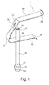
- FIG 1 shows a perspective view of a Kirschner wire clamp 1 according to the invention.
- the Kirschner wire clamp 1 shown in Figure 1 comprises a guide element 20.
- a base element 10 is provided, which is located in a first end region 21 of the guide element 20.
- the base element 10 comprises a diameter that exceeds that of the guide element.
- the base element can also be formed to the guide element so as to make a gradual transition, as shown in the figure in the section designated I.
- the base element comprises a fitting region 15, which in the embodiment shown tapers off in the direction pointing away from the guide element. This fitting region makes it possible to fit the base element into a through-opening 51 of a bone plate 50, wherein tapering off is used for positioning or centring the base element in the through-hole 51 of the bone plate 50.
- the Kirschner wire clamp comprises a clamping element 30 that is attached in an attachment region 35, for example by adhesive bonding, a solder connection, a weld connection and in particular a laser weld connection, or by a press fit.
- the clamping element 30 further comprises a clamping region 32 that is situated above the second end region 23 of the guide element 20.
- the term "above” refers to the clamping region being located in the direction of the opening of the guide element 20 in the region of the second end region 23, without mandatorily being located in each position above the opening of the second end region 23. In some excursion positions the clamping region 32 can also be situated beside the longitudinal axis of the guide element 20.
- the clamping region 32 can be situated in an opening, a recess 38 or a through-hole 34 of the clamping element 30, wherein the through-hole can be a round hole or an elongated hole, or a hole with any desired cross-sectional shape.
- the clamping element 30 comprises an elastic section 33 through which the two limbs of the clamping element 30 can be moved by the gripping regions 37, 39.
- the guide element 20 further comprises an interior wall region 24 against which in the region of the second end region 23 a Kirschner wire can be pushed through the clamping region 32 of the clamping element 30 in order to in this way fix the Kirschner wire to the Kirschner wire clamp.
- the gripping regions 37, 39 can, for example, comprise a certain curvature in order to prevent slipping during manual operation.
- all the edges including the gripping regions 37, 39 can be designed such that, for example, they cannot damage the protective gloves of an operator.
- the Kirschner wire clamp can essentially be made from surgical steels, wherein the materials used can be suitably selected by an average person skilled in the art as far as their sterilisability, stability or deformability are concerned. Transitions, for example in the fastening region 35 or between the guide element 20 and the base element 10, can be designed such that any depositing of particles can be prevented, for example by a design with gradual transitions.
- the Kirschner wire clamp can also, entirely or in part, be made of other suitable materials, for example plastics or fibre-reinforced materials, provided they are suitable for application as a Kirschner wire clamp. This may be advantageous, in particular, in the case of single-use as a disposable Kirschner wire clamp, due to low production costs.
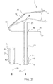
- FIG. 2 shows a section view of an exemplary embodiment of a Kirschner wire clamp according to the invention.
- the clamping element 30 can be brought from the home position C to a second position B by deformation of the elastic region 33 so that the opening 34 corresponds to the opening of the guide element 20 in the second end region 23.
- a Kirschner wire can be fed through the guide element 20 and the aperture 34, wherein the Kirschner wire with the clamping region 32 can be clamped to an interior wall side 24 in the end region 23 of the guide element 20.
- clamping can take place either in the wall region 24 or in the clamping region 32.
- clamping region 32 only refers to the fact that clamping of the Kirschner wire takes place, wherein it is not mandatory for the frictionally engaged fit or positive-fit connection to take place in the clamping region 32 but instead it can also take place at the interior wall region 24.
- the interior of the guide element 20 can also comprise an adhesion-reducing coating so that in this case it may be sensible to establish the frictionally engaged fit between the Kirschner wire and the clamping region 32 in order to cause reliable fixing of the Kirschner wire clamp 1 to the Kirschner wire.
- the elastic region 33 need not be limited to the position designated in Figure 2 , but instead can also extend across larger regions or across the entire clamping element 30.
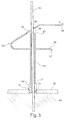
- FIG 3 shows a Kirschner wire clamp according to the invention in a position A that fixes a bone plate 50 to a bone 40.
- the Kirschner wire 60 extends from the bone 40 through a through-opening or a through-hole 51 of a bone plate 50.
- the Kirschner wire clamp is pushed over the Kirschner wire 60 into a location that in Figure 2 is designated position B, wherein the clamping element, which during installation is subjected to an excursion movement to position B, is subsequently released so that it moves to position A.
- the clamping element 30 cannot return to its originally taken-up home position C ( Figure 2 ) but instead with the clamping region 32 presses the Kirschner wire 60 to the interior wall region 24 of the second end region 23 of the guide element 20. In this process a frictionally engaged or positive-fit connection between the Kirschner wire 60 and the interior wall region 24, or a frictionally engaged or positive-fit connection between the Kirschner wire 60 and the clamping region 32 can take place.
- Figure 3 shows that the tapering-off fitting region 15 can serve as a centring device in the through-hole 51 of the bone plate 50 in order to in this way be able to reliably fix the bone plate 50 to the bone 40.
- Kirschner wire clamp according to the invention Kirschner wires of various diameters can be fixed because the design of the clamping mechanism allows a variable diameter of a Kirschner wire 60.
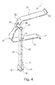
- Figure 4 shows a further exemplary embodiment of a Kirschner wire clamp according to the present invention.
- the embodiment shown in Figure 4 shows a Kirschner wire clamp in which the clamping element 30, the guide element 20 and the base element 10 are open towards one side so that a Kirschner wire 60 that protrudes beyond a bone 40 and through a through-hole 51 of a bone plate 50 can be laterally inserted into the guide element 20.
- the guide element 20 comprises a lateral opening 28 in the form of a slit that allows lateral insertion of a Kirschner wire. It is sensible if in the fastening region 35 a lateral opening in the clamping element 30 is also provided so that the Kirschner wire can be inserted without hindrance in the lateral slit 28.
- the base element 10 also comprises a lateral opening 18 in the form of a slit.
- the clamping element 30 comprises a recess 38 which also allows lateral insertion of a Kirschner wire.
- the Kirschner wire clamp shown in Figure 4 can be fixed to the Kirschner wire in order to fix a bone plate 50 to a surface of a bone 40.
- the present invention apart from the application in the case of Kirschner wires, can also be applied in the case of other, similar, wires and rods, in particular if the wires and rods provide adequate bending stability so that they allow corresponding clamping.
Landscapes
- Health & Medical Sciences (AREA)
- Orthopedic Medicine & Surgery (AREA)
- Life Sciences & Earth Sciences (AREA)
- Surgery (AREA)
- Medical Informatics (AREA)
- Engineering & Computer Science (AREA)
- Biomedical Technology (AREA)
- Heart & Thoracic Surgery (AREA)
- Nuclear Medicine, Radiotherapy & Molecular Imaging (AREA)
- Molecular Biology (AREA)
- Animal Behavior & Ethology (AREA)
- General Health & Medical Sciences (AREA)
- Public Health (AREA)
- Veterinary Medicine (AREA)
- Neurology (AREA)
- Surgical Instruments (AREA)
Abstract
Description
- The present invention relates to a Kirschner wire clamp for positioning a bone plate, in particular a Kirschner wire clamp, which allows more precise, easier and simpler positioning of a bone plate on a bone surface.
- In the treatment of bone fractures it is helpful and sometimes necessary if, prior to fixation of a fracture by bone plates, the fracture itself is stabilised. This is, in particular, helpful or necessary in cases where the bone fracture not only comprises two fragments but a multitude of fragments. In this case it may be necessary to stabilise the multitude of fragments in their original position before fastening corresponding bone plates and bone screws for fixation of the fracture. Such stabilisation and preliminary fixation are often achieved by so-called Kirschner wires, whose tips comprise a cutter that makes it possible, by a corresponding drill, to drill the Kirschner wires into and through the bone or the bone fragments and in this way to stabilise the bone fragments relative to each other. However, these Kirschner wires are often inadequate for fixation until final healing, so that subsequent positioning of bone plates needs to take place. In this process, Kirschner wires can be used to support positioning of a bone plate to be put in place. For this purpose, for example, a bone plate is placed on the corresponding bone surface, and a Kirschner wire is placed through a hole in the bone plate. By a Kirschner wire clamp, on the Kirschner wire anchored in the bone, the bone plate can be placed on the bone or on the bone surface, and can also be fastened thereto, such that the corresponding bone screws can be fixed simply and reliably through the remaining free openings or through-holes in the bone plate. By temporary attachment of the plate, additional hands (operating theatre personnel) can be saved, and, in order to check whether the fracture has been restored properly, the bone can be moved and rotated without the plate falling down, in particular if the plate is in an upside-down position as a result of rotation of the bone.
- However, the Kirschner wire clamps known from prior art are difficult to handle, make it impossible to carry out satisfactory preliminary fixation of a bone plate, comprise only limited functionality, or require significantly more time and space for their use.
- Against the background of prior art it can be considered as an object of the invention to provide a Kirschner wire clamp that makes fast and easy positioning possible.
- The object of the present invention is solved by the independent claims, wherein exemplary embodiments of the invention are embodied by the dependent claims.
- According to an exemplary embodiment of the invention, a Kirschner wire clamp is provided with a guide element, a base element and a clamping element, wherein the base element is arranged at a first end region of the guide element, wherein the clamping element comprises a clamping region, wherein the clamping region is arranged in a longitudinal direction of the guide element above, or spaced apart from, a second end region of the guide element.
- In this way a situation can be achieved in which the alignment of the base element takes place by the guide element on the Kirschner wire that has been put in place, so that, for example, a bone plate can be fixed to a bone surface by the base element. This makes it possible, in particular, to exactly align and reliably and quickly fix the bone plate by the Kirschner wire positioned in the bone. In this document the term guide element refers to an arrangement that makes it possible to align the Kirschner wire clamp on the Kirschner wire that has been put in position. However, the guide element can also be used to significantly simplify the narrow access to the bone or the plate through the soft tissue, and to ensure that the more space-intensive clamping element is situated outside the soft tissue. In this case the guide element can be used to guide the Kirschner wire through the tissue. In this arrangement the base element can be used as a foundation for defined fixing, and as a contact pressure element on the bone plate. The base element can be designed as a separate element, but it can equally be integrated in the end region of the guide element. In this arrangement the guide element and the base element can be designed in one piece; in other words the base element can make a gradual transition to the guide element. However, the base element can also be joined to the guide element. The base element can also be spaced apart from the first end region by spacers, wherein in this case the spacers are considered to form part of the base element. The term "clamping element" refers to an element that is able to fix the Kirschner wire on the Kirschner wire clamp in a frictionally engaged manner or having positive fit so that the position of the Kirschner wire clamp relative to the Kirschner wire can essentially no longer be changed just like that, i.e. without further exertion of force or without renewed operation of the clamp. In this context the term "above" refers to a continuation of the axis or line of longitudinal extension of the guide element in the direction of the second end region, and in this context can also be in direct contact with the second end region.
- According to an exemplary embodiment of the invention, the base element comprises a fitting region, wherein the fitting region is designed to engage a through-hole of a bone plate.
- The base element, which is, for example, fixed as an end region of the guide element, can thus comprise a fitting region at the position at which the Kirschner wire clamp presses against the bone plate to be fixed. In this arrangement it is possible, by the fitting region, for example to bring about positioning or centring of the base element on or in the through hole of a bone plate. In this arrangement the fitting region can have various embodiments, and can, for example, be designed to match through-openings or through-holes of bone plates. Of course, it is also possible for through-openings of bone plates to be designed so as to match the corresponding fitting regions of a Kirschner wire clamp, so that reliable fixing of the bone plate to the bone surface can take place. In this arrangement the through-holes can be designed with or without threads. In cases where the diameter of a Kirschner wire is essentially the same as that of a through-hole of a bone plate, the positive-fit connection between a face of the Kirschner wire clamp, which face points towards the plate, and the plate surface that surrounds the through-hole is established.
- According to an exemplary embodiment of the invention, the fitting region comprises a through-hole, wherein the through-hole extends in a direction that essentially corresponds to an axis of longitudinal extension of the guide element.
- In this manner it is possible to fix the bone plate by guiding the Kirschner wire through the fitting region or by the base element, which makes possible precise alignment of the Kirschner wire clamp and thus precise positioning of the bone plate on the bone surface.
- According to an exemplary embodiment of the invention, the fitting region tapers off in one direction, wherein this direction corresponds to a direction of longitudinal extension of the guide element and points away from said guide element.
- In this way it may become possible, by the base element which for example tapers off in the direction of the bone plate, or by the fitting region, to achieve automatic centring of the Kirschner wire in the through-hole of the bone plate. Furthermore, displacement of the bone plate may be prevented in this manner so that more reliable fixing of the bone plate to the bone surface is made possible.
- According to an exemplary embodiment of the invention, the guide element is designed to accommodate a Kirschner wire that has been put in place in a bone and that protrudes from the bone and through a through-hole of a bone plate.
- In this manner reliable fixing relating to the contact pressure and the position is made possible by the guide element accommodating the Kirschner wire. In this arrangement the through-hole of a bone plate can be a hole that is intended for accommodating a screw; but it can also be a special hole that is intended for guiding a Kirschner wire through it.
- According to an exemplary embodiment of the invention, the guide element is designed so as to be straight and tubular in shape.
- A straight design of the guide element makes it possible to insert a Kirschner wire, which as a rule is also straight, without any problems, wherein the tubular design prevents the Kirschner wire from unintentionally slipping from the guide element, which would make positioning of the bone plate on the bone surface more difficult. However, a curved sleeve is also possible, in which the Kirschner wire is clamped by the curvature so as to be fixed. In this arrangement the sleeve can be designed so as to be elastic so that by a further tool, for example suitable pliers it can be brought to straight alignment for the purpose of moving the Kirschner wire in or out. In this case an end region, arranged at a distance from the base element, of such a sleeve, which is also used as a guide element, will have to be considered as being the clamping region, wherein the actual guide element then extends from an end region, which faces the base element, to the interior wall region of the sleeve, which interior wall region is located radially opposite the clamping region in the sleeve, and is used as an abutment for clamping the Kirschner wire.
- According to an exemplary embodiment of the invention, the clamping element comprises a leaf spring or an elastic region that is used as a leaf spring.
- A leaf spring has a simple geometric shape that is easy to clean, by which a clamping region of the clamping element can clamp-fix the Kirschner wire to the Kirschner wire clamp.
- According to an exemplary embodiment of the invention, the clamping element is movable between a first position and a second position, wherein the clamping region is designed in the first position to laterally press a Kirschner wire that protrudes beyond the second end region to an interior wall region of the guide element.
- In this arrangement the clamping element can fix the Kirschner wire to the guide element not only in a frictionally engaged manner and/or having positive fit on the inside of the guide element, but said clamping element can also fix the Kirschner wire to the clamping region itself in a frictionally engaged manner and/or having positive fit. In this arrangement the clamping region can produce a frictionally engaged connection with the Kirschner wire, however, additionally or as an alternative, it can also establish a positive-fit connection by minimum deformation of the Kirschner wire in the clamping region, which connection prevents the Kirschner wire clamp from sliding from the Kirschner wire. In this manner reliable fixing of the Kirschner wire clamp to the Kirschner wire, and thus reliable fixing of the bone plate to the bone surface, is made possible.
- According to an exemplary embodiment of the invention, the clamping element comprises a recess or a hole as a clamping region, wherein the clamping element further comprises a fastening region that is attached to the guide element.
- In this arrangement a hole in the clamping element may prevent the Kirschner wire from unintentionally moving or sliding from its normal position, whereas a recess with, for example, a lateral opening makes it possible to insert the Kirschner wire also laterally into the clamping element, for example if this is required for reasons of available space. In this arrangement the clamping element can comprise a cutting edge that improves fixing the Kirschner wire to the contact position of the clamping region. The fastening region of the clamping element can be attached to the guide element, for example by soldering, adhesively bonding, welding and in particular laser welding, or by a press fit.
- According to an exemplary embodiment of the invention, the recess or the hole in the second position corresponds with the direction of longitudinal extension of the guide element such that a Kirschner wire that protrudes beyond a bone and through a through-hole of a bone plate can be inserted into the guide element in a direction of longitudinal extension of the guide element.
- In other words the clamping element that is in the second position makes it possible to position the Kirschner wire clamp on the Kirschner wire, wherein fixing the Kirschner wire clamp on the Kirschner wire takes place by a movement of the clamping element to the first position. It should be mentioned that the clamping element can take still further positions, wherein in particular the home position of the clamping element can be a position that differs from the first position and the second position. In particular, in this arrangement the first position can be located between the second position and the home position. Furthermore, it should be mentioned that the clamping element can be moved from the home position to the first position or to the second position by exertion of force in which the leaf spring is moved out of its home position.
- According to an exemplary embodiment of the invention, the clamping element comprises the following regions along its extension in the following order: a first gripping region, a fastening region, an elastic region, a clamping region and a second gripping region.
- As a result of the gripping regions it is possible for an operator to move the clamping element between the different positions in that the clamping element is subjected to deformation, in particular to reversible deformation, in the elastic region, e.g. in a leaf spring region. In this arrangement the clamping element can be bent in order to make single-handed operation possible. As a result of the arrangement of an attachment region, an elastic region and a clamping region between the first gripping region and the second gripping region, the lever arms of the clamping element can be selected to be large so that activation, in particular deformation of the elastic region, can be carried out simply by single-handed activation. Furthermore, as a result of such a design the clamping region can be moved precisely and easily so that simple and precise operation of the Kirschner wire clamp becomes possible.
- According to an exemplary embodiment of the invention, the clamping element, the guide element and the base element are open towards one side such that a Kirschner wire that protrudes beyond a bone and through a through-hole of a bone plate can be inserted laterally into the guide element.
- In this arrangement, for example, a hole present in the clamping element can comprise a lateral opening so that the Kirschner wire can be laterally inserted into the hole located in the clamping element without "threading" having to take place by way of the end of the Kirschner wire. Likewise, the attachment region of the clamping element can be laterally open in the region of the guide element in order to make it possible to laterally insert a Kirschner wire. Such a lateral opening is in particular advantageous if the available space is restricted or if the end of the Kirschner wire is not easily accessible just like that, or if, due to the inherent situation of an operation the Kirschner wire clamp cannot be moved to the bone plate by way of the free end of the Kirschner wire with its base element.
- According to an exemplary embodiment of the invention, in defined regions the clamping element can be designed so as to laterally taper off, in particular in the elastic region of the clamping element, in order to in this way make possible easier deformability or elastic bendability of the clamping element.
- It should be noted that the individual features can of course also be combined, as a result of which, in part, advantageous effects may arise which exceed the sum of the individual effects.
- These and other aspects of the present invention are explained and clarified with reference to the exemplary embodiments described hereafter.
- Below, exemplary embodiments are described with reference to the following drawings.
-
Figure 1 shows a perspective view of a Kirschner wire clamp according to the invention. -
Figure 2 shows a section view of a Kirschner wire clamp according to the invention with two possible positions of the clamping element. -
Figure 3 shows a Kirschner wire clamp according to the invention in an installed state together with a fixed Kirschner wire and a bone plate located on a bone surface. -
Figure 4 shows a Kirschner wire clamp according to a further exemplary embodiment with a lateral opening. -
Figure 1 shows a perspective view of a Kirschner wire clamp 1 according to the invention. The Kirschner wire clamp 1 shown inFigure 1 comprises aguide element 20. Furthermore, abase element 10 is provided, which is located in afirst end region 21 of theguide element 20. In the exemplary embodiment shown, thebase element 10 comprises a diameter that exceeds that of the guide element. However, this is not mandatory. Instead, the base element can also be formed to the guide element so as to make a gradual transition, as shown in the figure in the section designated I. In this case that part which essentially is used to guide a Kirschner wire is to be understood to be the guide element, while the base element is understood to be the part which essentially is used as a foundation for the Kirschner wire clamp on the bone plate, in which bone plate the exertion of force for fixing the bone place takes place by way of the base element. In the embodiment shown the base element comprises afitting region 15, which in the embodiment shown tapers off in the direction pointing away from the guide element. This fitting region makes it possible to fit the base element into a through-opening 51 of abone plate 50, wherein tapering off is used for positioning or centring the base element in the through-hole 51 of thebone plate 50. Furthermore, the Kirschner wire clamp comprises a clampingelement 30 that is attached in anattachment region 35, for example by adhesive bonding, a solder connection, a weld connection and in particular a laser weld connection, or by a press fit. The clampingelement 30 further comprises a clampingregion 32 that is situated above thesecond end region 23 of theguide element 20. In this context the term "above" refers to the clamping region being located in the direction of the opening of theguide element 20 in the region of thesecond end region 23, without mandatorily being located in each position above the opening of thesecond end region 23. In some excursion positions the clampingregion 32 can also be situated beside the longitudinal axis of theguide element 20. In this arrangement the clampingregion 32 can be situated in an opening, arecess 38 or a through-hole 34 of the clampingelement 30, wherein the through-hole can be a round hole or an elongated hole, or a hole with any desired cross-sectional shape. In at least one region the clampingelement 30 comprises anelastic section 33 through which the two limbs of the clampingelement 30 can be moved by the grippingregions guide element 20 further comprises aninterior wall region 24 against which in the region of the second end region 23 a Kirschner wire can be pushed through the clampingregion 32 of the clampingelement 30 in order to in this way fix the Kirschner wire to the Kirschner wire clamp. In this arrangement the grippingregions gripping regions - The Kirschner wire clamp can essentially be made from surgical steels, wherein the materials used can be suitably selected by an average person skilled in the art as far as their sterilisability, stability or deformability are concerned. Transitions, for example in the
fastening region 35 or between theguide element 20 and thebase element 10, can be designed such that any depositing of particles can be prevented, for example by a design with gradual transitions. - Of course, the Kirschner wire clamp can also, entirely or in part, be made of other suitable materials, for example plastics or fibre-reinforced materials, provided they are suitable for application as a Kirschner wire clamp. This may be advantageous, in particular, in the case of single-use as a disposable Kirschner wire clamp, due to low production costs.
-
Figure 2 shows a section view of an exemplary embodiment of a Kirschner wire clamp according to the invention. In the section view shown, at least a region of the clampingelement 30 can be brought from the home position C to a second position B by deformation of theelastic region 33 so that theopening 34 corresponds to the opening of theguide element 20 in thesecond end region 23. In this excursion state a Kirschner wire can be fed through theguide element 20 and theaperture 34, wherein the Kirschner wire with the clampingregion 32 can be clamped to aninterior wall side 24 in theend region 23 of theguide element 20. In this arrangement clamping can take place either in thewall region 24 or in the clampingregion 32. In this context the term "clamping region" 32 only refers to the fact that clamping of the Kirschner wire takes place, wherein it is not mandatory for the frictionally engaged fit or positive-fit connection to take place in the clampingregion 32 but instead it can also take place at theinterior wall region 24. However, for improved insertability of the Kirschner wire, the interior of theguide element 20 can also comprise an adhesion-reducing coating so that in this case it may be sensible to establish the frictionally engaged fit between the Kirschner wire and the clampingregion 32 in order to cause reliable fixing of the Kirschner wire clamp 1 to the Kirschner wire. - In this arrangement the
elastic region 33 need not be limited to the position designated inFigure 2 , but instead can also extend across larger regions or across theentire clamping element 30. -
Figure 3 shows a Kirschner wire clamp according to the invention in a position A that fixes abone plate 50 to abone 40. In this arrangement theKirschner wire 60 extends from thebone 40 through a through-opening or a through-hole 51 of abone plate 50. In this arrangement the Kirschner wire clamp is pushed over theKirschner wire 60 into a location that inFigure 2 is designated position B, wherein the clamping element, which during installation is subjected to an excursion movement to position B, is subsequently released so that it moves to position A. Due to the insertedKirschner wire 60 the clampingelement 30 cannot return to its originally taken-up home position C (Figure 2 ) but instead with the clampingregion 32 presses theKirschner wire 60 to theinterior wall region 24 of thesecond end region 23 of theguide element 20. In this process a frictionally engaged or positive-fit connection between theKirschner wire 60 and theinterior wall region 24, or a frictionally engaged or positive-fit connection between theKirschner wire 60 and the clampingregion 32 can take place. As a result of the design of the clampingregion 32 with, for example, a cutting edge, by only slight deformation of the outside region of theKirschner wire 60 it is also possible to bring about a positive-fit connection between the Kirschner wire and the clampingregion 32, which prevents any relative movement between theKirschner wire 60 and the Kirschner wire clamp. - Furthermore,
Figure 3 shows that the tapering-offfitting region 15 can serve as a centring device in the through-hole 51 of thebone plate 50 in order to in this way be able to reliably fix thebone plate 50 to thebone 40. It should be noted that with the Kirschner wire clamp according to the invention Kirschner wires of various diameters can be fixed because the design of the clamping mechanism allows a variable diameter of aKirschner wire 60. -
Figure 4 shows a further exemplary embodiment of a Kirschner wire clamp according to the present invention. The embodiment shown inFigure 4 shows a Kirschner wire clamp in which theclamping element 30, theguide element 20 and thebase element 10 are open towards one side so that aKirschner wire 60 that protrudes beyond abone 40 and through a through-hole 51 of abone plate 50 can be laterally inserted into theguide element 20. - For this purpose the
guide element 20 comprises alateral opening 28 in the form of a slit that allows lateral insertion of a Kirschner wire. It is sensible if in the fastening region 35 a lateral opening in the clampingelement 30 is also provided so that the Kirschner wire can be inserted without hindrance in the lateral slit 28. In the embodiment shown inFigure 4 thebase element 10 also comprises alateral opening 18 in the form of a slit. Corresponding thereto, the clampingelement 30 comprises arecess 38 which also allows lateral insertion of a Kirschner wire. - With the embodiment shown in
Figure 4 it is possible to simply and reliably fix a bone plate to a bone surface by a Kirschner wire fastened to the bone without the free end of the Kirschner wire having to be accessible. Instead, in an installation region that is not much larger than the length of the Kirschner wire clamp, the Kirschner wire clamp shown inFigure 4 can be fixed to the Kirschner wire in order to fix abone plate 50 to a surface of abone 40. - It should be noted that the present invention, apart from the application in the case of Kirschner wires, can also be applied in the case of other, similar, wires and rods, in particular if the wires and rods provide adequate bending stability so that they allow corresponding clamping.
- Furthermore, it should be noted that "comprising" does not exclude other elements or process-related steps, and "a" or "an" does not exclude a plural number of elements or steps.
Claims (12)
- A Kirschner wire clamp witha guide element (20);a base element (10); anda clamping element (30);wherein the base element (10) is arranged on a first end region (21) of the guide element (20);
wherein the clamping element (30) comprises a clamping region (32);
wherein the clamping region (32) is arranged above the second end region (23). - The Kirschner wire clamp according to claim 1, wherein the base element (10) comprises a fitting region (15);
wherein the fitting region (15) is designed to engage a through-hole (51) of a bone plate (50). - The Kirschner wire clamp according to claim 2, wherein the fitting region (15) comprises a through-hole (16), wherein the through-hole (16) extends in a direction that essentially corresponds to an axis (29) of longitudinal extension of the guide element (20).
- The Kirschner wire clamp according to one of claims 2 or 3, wherein the fitting region (15) tapers off in one direction which corresponds to a direction (29) of longitudinal extension of the guide element (20) and points away from said guide element (20).
- The Kirschner wire clamp according to any one of the preceding claims, wherein the guide element (20) is designed to accommodate a Kirschner wire (60) that has been put in place in a bone (40) and that protrudes from the bone (40) and through a through-hole (51) of a bone plate (50).
- The Kirschner wire clamp according to any one of the preceding claims, wherein the guide element (20) is designed so as to be straight and tubular in shape.
- The Kirschner wire clamp according to any one of the preceding claims, wherein the clamping element (30) comprises a leaf spring (33).
- The Kirschner wire clamp according to any one of the preceding claims, wherein the clamping element (30) is movable between a first position (A) and a second position (B), wherein the clamping region (32) is designed in position (A) to laterally press a Kirschner wire (60) that protrudes beyond the second end region (23) to an interior wall region (24) of the guide element (20).
- The Kirschner wire clamp according to any one of the preceding claims, wherein the clamping element (30) comprises a recess (38) or a hole (34) as a clamping region (32), and further comprises a fastening region (35) that is attached to the guide element (20).
- The Kirschner wire clamp according to claim 9, wherein the recess (34) or the hole (34) in the second position (B) agrees with the direction (29) of longitudinal extension of the guide element (20) such that a Kirschner wire (60) that protrudes beyond a bone (40) and through a through-hole (51) of a bone plate (50) can be inserted into the guide element (20) in a direction (29) of longitudinal extension of the guide element (20).
- The Kirschner wire clamp according to any one of the preceding claims, wherein the clamping element (30) comprises the following along its extension in the following order: a first gripping region (37), a fastening region (35), an elastic region (33), a clamping region (32) and a second gripping region (39).
- The Kirschner wire clamp according to any one of the preceding claims, wherein the clamping element (30), the guide element (20) and the base element (10) are open towards one side (28; 38) such that a Kirschner wire (60) that protrudes beyond a bone (40) and through a through-hole (51) of a bone plate (50) can be inserted laterally into the guide element (20).
Applications Claiming Priority (1)
| Application Number | Priority Date | Filing Date | Title |
|---|---|---|---|
| DE200820000914 DE202008000914U1 (en) | 2008-01-22 | 2008-01-22 | Kirschner wire clamp |
Publications (3)
| Publication Number | Publication Date |
|---|---|
| EP2082698A2 true EP2082698A2 (en) | 2009-07-29 |
| EP2082698A3 EP2082698A3 (en) | 2010-04-21 |
| EP2082698B1 EP2082698B1 (en) | 2012-05-30 |
Family
ID=39199035
Family Applications (1)
| Application Number | Title | Priority Date | Filing Date |
|---|---|---|---|
| EP20090150688 Active EP2082698B1 (en) | 2008-01-22 | 2009-01-16 | Kirschner wire clamp |
Country Status (4)
| Country | Link |
|---|---|
| US (1) | US9089378B2 (en) |
| EP (1) | EP2082698B1 (en) |
| DE (1) | DE202008000914U1 (en) |
| ES (1) | ES2387526T3 (en) |
Cited By (2)
| Publication number | Priority date | Publication date | Assignee | Title |
|---|---|---|---|---|
| EP2810606A1 (en) | 2013-06-07 | 2014-12-10 | Stryker Trauma GmbH | Sleeve clamp |
| US11076899B2 (en) | 2016-07-25 | 2021-08-03 | Olympus Terumo Biomaterials Corp. | Pressing tool for bone surgery |
Families Citing this family (30)
| Publication number | Priority date | Publication date | Assignee | Title |
|---|---|---|---|---|
| US7951176B2 (en) | 2003-05-30 | 2011-05-31 | Synthes Usa, Llc | Bone plate |
| US11259851B2 (en) | 2003-08-26 | 2022-03-01 | DePuy Synthes Products, Inc. | Bone plate |
| NZ545392A (en) | 2003-08-26 | 2008-03-28 | Synthes Gmbh | Bone plate |
| US11291484B2 (en) | 2004-01-26 | 2022-04-05 | DePuy Synthes Products, Inc. | Highly-versatile variable-angle bone plate system |
| US8574268B2 (en) | 2004-01-26 | 2013-11-05 | DePuy Synthes Product, LLC | Highly-versatile variable-angle bone plate system |
| ITTO20080845A1 (en) * | 2008-11-17 | 2010-05-18 | Intrauma S R L | INSTRUMENT FOR INSERTION OF DRIVING WIRES IN A FRACTURE BONE. |
| CA2805109C (en) | 2010-07-14 | 2018-05-29 | DePuy Synthes Products, Inc. | Assemblies for aligning a bone fixation plate |
| US8992579B1 (en) | 2011-03-08 | 2015-03-31 | Nuvasive, Inc. | Lateral fixation constructs and related methods |
| US9060815B1 (en) | 2012-03-08 | 2015-06-23 | Nuvasive, Inc. | Systems and methods for performing spine surgery |
| US9517089B1 (en) | 2013-10-08 | 2016-12-13 | Nuvasive, Inc. | Bone anchor with offset rod connector |
| US9549768B2 (en) | 2014-04-17 | 2017-01-24 | Biomet Manufacturing, Llc | Medical implant system for securing bone fragments |
| DE102014107882A1 (en) * | 2014-06-04 | 2015-12-17 | Aesculap Ag | K-wire system |
| US10905476B2 (en) | 2016-09-08 | 2021-02-02 | DePuy Synthes Products, Inc. | Variable angle bone plate |
| US10820930B2 (en) | 2016-09-08 | 2020-11-03 | DePuy Synthes Products, Inc. | Variable angle bone plate |
| US10624686B2 (en) | 2016-09-08 | 2020-04-21 | DePuy Synthes Products, Inc. | Variable angel bone plate |
| US11026727B2 (en) | 2018-03-20 | 2021-06-08 | DePuy Synthes Products, Inc. | Bone plate with form-fitting variable-angle locking hole |
| US10772665B2 (en) | 2018-03-29 | 2020-09-15 | DePuy Synthes Products, Inc. | Locking structures for affixing bone anchors to a bone plate, and related systems and methods |
| US11013541B2 (en) | 2018-04-30 | 2021-05-25 | DePuy Synthes Products, Inc. | Threaded locking structures for affixing bone anchors to a bone plate, and related systems and methods |
| US11109900B2 (en) | 2018-11-29 | 2021-09-07 | Gbr99 Ip, Llc | Extramedullary compression and fixation device, system and method |
| US10925651B2 (en) | 2018-12-21 | 2021-02-23 | DePuy Synthes Products, Inc. | Implant having locking holes with collection cavity for shavings |
| WO2020172280A1 (en) | 2019-02-21 | 2020-08-27 | Glw, Inc. | Hybrid bone fixation wire |
| US20240041506A1 (en) * | 2019-03-11 | 2024-02-08 | Edge Surgical, Inc. | Bending the probes of depth gauges |
| CN110974391A (en) * | 2019-12-29 | 2020-04-10 | 长春圣博玛生物材料有限公司 | A kind of auxiliary positioning sleeve with wire anchor |
| US20240277390A1 (en) * | 2020-01-20 | 2024-08-22 | Trimed Inc. | Method and apparatus for maintaining a position of a bone fragment in relationship to another bone part |
| US12533169B2 (en) * | 2020-09-04 | 2026-01-27 | Arbutus Medical Inc. | Traction pin assemblies, components, systems, and methods |
| CN111991068B (en) * | 2020-09-19 | 2024-06-21 | 苏州爱科硕科技有限公司 | Kirschner wire chuck |
| EP4319658A1 (en) | 2021-04-06 | 2024-02-14 | GLW, Inc. | Bone fixation devices, systems, kits, and methods |
| TWD227883S (en) * | 2023-03-08 | 2023-10-01 | 博晟生醫股份有限公司 | Medical implantable device set |
| WO2024230733A1 (en) * | 2023-05-10 | 2024-11-14 | 苏州柯弗尔医疗科技有限公司 | Bone pin guiding and locking assembly and fixing system comprising same |
| US12226135B1 (en) | 2024-02-13 | 2025-02-18 | Surgeon Design Center LLC. | Surgical guide wire engagement device |
Family Cites Families (20)
| Publication number | Priority date | Publication date | Assignee | Title |
|---|---|---|---|---|
| US185127A (en) * | 1876-12-05 | Improvement in upholsterers button attachments | ||
| US977704A (en) * | 1909-06-21 | 1910-12-06 | James L Brownlee | Spring-clip for reinforcing-bars. |
| US2216886A (en) * | 1939-07-31 | 1940-10-08 | Wilfred F Langelier | Holder |
| US2279068A (en) * | 1940-12-11 | 1942-04-07 | John R Siebrandt | Wire crimping and twisting tool |
| US2654932A (en) * | 1948-10-05 | 1953-10-13 | Devere Company | Sheet clamping device |
| FR1161507A (en) | 1956-10-03 | 1958-09-01 | Sarl Drapier | Continuous pressure external compressor for bone fracture reduction |
| GB1052151A (en) * | 1964-06-18 | |||
| US3415473A (en) * | 1966-12-23 | 1968-12-10 | Reginald I. Ollen | Pipe hanger |
| CH590376A5 (en) * | 1974-09-02 | 1977-08-15 | Hilti Ag | |
| US4920958A (en) * | 1986-11-05 | 1990-05-01 | Minnesota Mining And Manufacturing Company | Drill guide assembly |
| US5569253A (en) * | 1994-03-29 | 1996-10-29 | Danek Medical, Inc. | Variable-angle surgical cable crimp assembly and method |
| DE29913994U1 (en) | 1999-08-11 | 2000-12-21 | Synthes AG Chur, Chur, Graubünden | Surgical guide plate |
| US7575578B2 (en) * | 2002-02-13 | 2009-08-18 | Karl Storz Gmbh & Co. Kg | Surgical drill guide |
| DE20204655U1 (en) | 2002-03-21 | 2002-06-13 | stryker Trauma GmbH, 24232 Schönkirchen | Locking nail and target device |
| EP1651123B1 (en) * | 2003-08-08 | 2011-01-12 | Synthes GmbH | Clamping device |
| ES2281826T3 (en) | 2003-09-22 | 2007-10-01 | Basf Aktiengesellschaft | FUNGICIDE BLENDS. |
| US20050173949A1 (en) * | 2004-01-12 | 2005-08-11 | Janet Hart | Swing wing |
| DE102004014036B4 (en) | 2004-03-19 | 2010-11-04 | Königsee Implantate und Instrumente zur Osteosynthese GmbH | Device for intraoperable fixation of bone fragments |
| US8152837B2 (en) | 2004-10-20 | 2012-04-10 | The Board Of Trustees Of The Leland Stanford Junior University | Systems and methods for posterior dynamic stabilization of the spine |
| US7837717B2 (en) * | 2006-03-24 | 2010-11-23 | Depuy Products, Inc. | Fastening system for internal fixation |
-
2008
- 2008-01-22 DE DE200820000914 patent/DE202008000914U1/en not_active Expired - Lifetime
-
2009
- 2009-01-16 US US12/321,378 patent/US9089378B2/en active Active
- 2009-01-16 EP EP20090150688 patent/EP2082698B1/en active Active
- 2009-01-16 ES ES09150688T patent/ES2387526T3/en active Active
Non-Patent Citations (1)
| Title |
|---|
| None |
Cited By (2)
| Publication number | Priority date | Publication date | Assignee | Title |
|---|---|---|---|---|
| EP2810606A1 (en) | 2013-06-07 | 2014-12-10 | Stryker Trauma GmbH | Sleeve clamp |
| US11076899B2 (en) | 2016-07-25 | 2021-08-03 | Olympus Terumo Biomaterials Corp. | Pressing tool for bone surgery |
Also Published As
| Publication number | Publication date |
|---|---|
| EP2082698B1 (en) | 2012-05-30 |
| US9089378B2 (en) | 2015-07-28 |
| EP2082698A3 (en) | 2010-04-21 |
| DE202008000914U1 (en) | 2008-03-20 |
| ES2387526T3 (en) | 2012-09-25 |
| US20090216242A1 (en) | 2009-08-27 |
| US20100211078A9 (en) | 2010-08-19 |
Similar Documents
| Publication | Publication Date | Title |
|---|---|---|
| EP2082698B1 (en) | Kirschner wire clamp | |
| US20080188859A1 (en) | Surgical instrument for implanting a wire, preferably into a bone | |
| EP0891159B1 (en) | Adjustable clamp for bone fixation element | |
| US8491599B2 (en) | Apparatus and method for aiming a surgical tool | |
| US20110238068A1 (en) | Device for shortening an elongated bone | |
| EP1872733A1 (en) | Bone plate clamp | |
| US10939945B2 (en) | Minimally invasive bone fracture positioning device | |
| KR20130141426A (en) | Protection sleeve holding mechanism | |
| EP0686375A1 (en) | Surgical instrument for use during connection of a fractured bone | |
| US20170209192A1 (en) | Bone reduction and implant holding instrument | |
| EP2958509B1 (en) | Surgical template arrangement and method | |
| CN214342492U (en) | Osteotomy tool | |
| KR101587456B1 (en) | Medical treatment for bone fixation device | |
| KR101110107B1 (en) | Drill guide | |
| CN111388080A (en) | Orthopedic parallel pressurizing positioner | |
| JP5431812B2 (en) | Bone surgery instrument and manufacturing method thereof | |
| EP3376973B1 (en) | Variable curve jig for an intramedullary device | |
| WO2021240287A1 (en) | K-wire implants for fractures | |
| US20260123968A1 (en) | Devices and methods for bone distraction, compression, & rotation | |
| EP2636378A1 (en) | Surgical power tool | |
| EP3232964B1 (en) | Guide wire control device | |
| CN219782710U (en) | Medical tool | |
| CN117017417A (en) | Orthopaedics positioner for wrist and palm joint | |
| JP4512902B2 (en) | Intramedullary nail positioning device | |
| US20080177290A1 (en) | Bone clamp assembly |
Legal Events
| Date | Code | Title | Description |
|---|---|---|---|
| PUAI | Public reference made under article 153(3) epc to a published international application that has entered the european phase |
Free format text: ORIGINAL CODE: 0009012 |
|
| AK | Designated contracting states |
Kind code of ref document: A2 Designated state(s): AT BE BG CH CY CZ DE DK EE ES FI FR GB GR HR HU IE IS IT LI LT LU LV MC MK MT NL NO PL PT RO SE SI SK TR |
|
| AX | Request for extension of the european patent |
Extension state: AL BA RS |
|
| PUAL | Search report despatched |
Free format text: ORIGINAL CODE: 0009013 |
|
| AK | Designated contracting states |
Kind code of ref document: A3 Designated state(s): AT BE BG CH CY CZ DE DK EE ES FI FR GB GR HR HU IE IS IT LI LT LU LV MC MK MT NL NO PL PT RO SE SI SK TR |
|
| AX | Request for extension of the european patent |
Extension state: AL BA RS |
|
| 17P | Request for examination filed |
Effective date: 20100831 |
|
| AKX | Designation fees paid |
Designated state(s): CH DE ES FR GB IT LI |
|
| 17Q | First examination report despatched |
Effective date: 20110411 |
|
| GRAP | Despatch of communication of intention to grant a patent |
Free format text: ORIGINAL CODE: EPIDOSNIGR1 |
|
| GRAS | Grant fee paid |
Free format text: ORIGINAL CODE: EPIDOSNIGR3 |
|
| GRAA | (expected) grant |
Free format text: ORIGINAL CODE: 0009210 |
|
| AK | Designated contracting states |
Kind code of ref document: B1 Designated state(s): CH DE ES FR GB IT LI |
|
| REG | Reference to a national code |
Ref country code: GB Ref legal event code: FG4D |
|
| REG | Reference to a national code |
Ref country code: CH Ref legal event code: EP |
|
| REG | Reference to a national code |
Ref country code: DE Ref legal event code: R096 Ref document number: 602009007264 Country of ref document: DE Effective date: 20120726 |
|
| REG | Reference to a national code |
Ref country code: CH Ref legal event code: NV Representative=s name: ISLER & PEDRAZZINI AG |
|
| REG | Reference to a national code |
Ref country code: ES Ref legal event code: FG2A Ref document number: 2387526 Country of ref document: ES Kind code of ref document: T3 Effective date: 20120925 |
|
| PLBE | No opposition filed within time limit |
Free format text: ORIGINAL CODE: 0009261 |
|
| STAA | Information on the status of an ep patent application or granted ep patent |
Free format text: STATUS: NO OPPOSITION FILED WITHIN TIME LIMIT |
|
| 26N | No opposition filed |
Effective date: 20130301 |
|
| REG | Reference to a national code |
Ref country code: DE Ref legal event code: R097 Ref document number: 602009007264 Country of ref document: DE Effective date: 20130301 |
|
| PGFP | Annual fee paid to national office [announced via postgrant information from national office to epo] |
Ref country code: IT Payment date: 20150122 Year of fee payment: 7 |
|
| REG | Reference to a national code |
Ref country code: FR Ref legal event code: PLFP Year of fee payment: 8 |
|
| PGFP | Annual fee paid to national office [announced via postgrant information from national office to epo] |
Ref country code: ES Payment date: 20151214 Year of fee payment: 8 |
|
| REG | Reference to a national code |
Ref country code: CH Ref legal event code: PUE Owner name: STRYKER EUROPEAN HOLDINGS VI, LLC, US Free format text: FORMER OWNER: STRYKER TRAUMA GMBH, DE Ref country code: CH Ref legal event code: PUE Owner name: STRYKER EUROPEAN HOLDINGS I, LLC, US Free format text: FORMER OWNER: STRYKER EUROPEAN HOLDINGS VI, LLC, US |
|
| REG | Reference to a national code |
Ref country code: DE Ref legal event code: R081 Ref document number: 602009007264 Country of ref document: DE Owner name: STRYKER EUROPEAN OPERATIONS HOLDINGS LLC, KALA, US Free format text: FORMER OWNER: STRYKER EUROPEAN HOLDINGS VI, LLC (N.D. GES. D. STAATES DELAWARE), KALAMAZOO, MICH., US Ref country code: DE Ref legal event code: R081 Ref document number: 602009007264 Country of ref document: DE Owner name: STRYKER EUROPEAN OPERATIONS HOLDINGS LLC, KALA, US Free format text: FORMER OWNER: STRYKER TRAUMA GMBH, 24232 SCHOENKIRCHEN, DE Ref country code: DE Ref legal event code: R082 Ref document number: 602009007264 Country of ref document: DE Representative=s name: MAIWALD PATENTANWALTSGESELLSCHAFT MBH, DE Ref country code: DE Ref legal event code: R081 Ref document number: 602009007264 Country of ref document: DE Owner name: STRYKER EUROPEAN HOLDINGS I, LLC (N.D. GES. D., US Free format text: FORMER OWNER: STRYKER TRAUMA GMBH, 24232 SCHOENKIRCHEN, DE Ref country code: DE Ref legal event code: R081 Ref document number: 602009007264 Country of ref document: DE Owner name: STRYKER EUROPEAN HOLDINGS I, LLC (N.D. GES. D., US Free format text: FORMER OWNER: STRYKER EUROPEAN HOLDINGS VI, LLC (N.D. GES. D. STAATES DELAWARE), KALAMAZOO, MICH., US Ref country code: DE Ref legal event code: R082 Ref document number: 602009007264 Country of ref document: DE Representative=s name: MAIWALD PATENTANWALTS- UND RECHTSANWALTSGESELL, DE |
|
| REG | Reference to a national code |
Ref country code: GB Ref legal event code: 732E Free format text: REGISTERED BETWEEN 20161006 AND 20161012 |
|
| REG | Reference to a national code |
Ref country code: GB Ref legal event code: 732E Free format text: REGISTERED BETWEEN 20161013 AND 20161019 |
|
| REG | Reference to a national code |
Ref country code: ES Ref legal event code: PC2A Owner name: STRYKER EUROPEAN HOLDINGS I, LLC Effective date: 20161115 |
|
| REG | Reference to a national code |
Ref country code: FR Ref legal event code: TP Owner name: STRYKER EUROPEAN HOLDINGS I, LLC, US Effective date: 20161108 |
|
| REG | Reference to a national code |
Ref country code: FR Ref legal event code: PLFP Year of fee payment: 9 |
|
| PG25 | Lapsed in a contracting state [announced via postgrant information from national office to epo] |
Ref country code: IT Free format text: LAPSE BECAUSE OF NON-PAYMENT OF DUE FEES Effective date: 20160116 |
|
| REG | Reference to a national code |
Ref country code: FR Ref legal event code: PLFP Year of fee payment: 10 |
|
| PG25 | Lapsed in a contracting state [announced via postgrant information from national office to epo] |
Ref country code: ES Free format text: LAPSE BECAUSE OF NON-PAYMENT OF DUE FEES Effective date: 20170117 |
|
| REG | Reference to a national code |
Ref country code: ES Ref legal event code: FD2A Effective date: 20181114 |
|
| REG | Reference to a national code |
Ref country code: CH Ref legal event code: PUE Owner name: STRYKER EUROPEANS OPERATIONS HOLDINGS LLC, US Free format text: FORMER OWNER: STRYKER EUROPEAN HOLDINGS I, LLC, US |
|
| REG | Reference to a national code |
Ref country code: CH Ref legal event code: PK Free format text: BERICHTIGUNG INHABER |
|
| REG | Reference to a national code |
Ref country code: DE Ref legal event code: R082 Ref document number: 602009007264 Country of ref document: DE Representative=s name: MAIWALD PATENTANWALTS- UND RECHTSANWALTSGESELL, DE Ref country code: DE Ref legal event code: R081 Ref document number: 602009007264 Country of ref document: DE Owner name: STRYKER EUROPEAN OPERATIONS HOLDINGS LLC, KALA, US Free format text: FORMER OWNER: STRYKER EUROPEAN HOLDINGS I, LLC (N.D. GES. D. STAATES DELAWARE), KALAMAZOO, MICH., US |
|
| REG | Reference to a national code |
Ref country code: GB Ref legal event code: 732E Free format text: REGISTERED BETWEEN 20210408 AND 20210414 |
|
| P01 | Opt-out of the competence of the unified patent court (upc) registered |
Effective date: 20230522 |
|
| PGFP | Annual fee paid to national office [announced via postgrant information from national office to epo] |
Ref country code: GB Payment date: 20251204 Year of fee payment: 18 |
|
| PGFP | Annual fee paid to national office [announced via postgrant information from national office to epo] |
Ref country code: FR Payment date: 20251208 Year of fee payment: 18 |
|
| REG | Reference to a national code |
Ref country code: CH Ref legal event code: U11 Free format text: ST27 STATUS EVENT CODE: U-0-0-U10-U11 (AS PROVIDED BY THE NATIONAL OFFICE) Effective date: 20260201 |
|
| PGFP | Annual fee paid to national office [announced via postgrant information from national office to epo] |
Ref country code: DE Payment date: 20251203 Year of fee payment: 18 |
|
| PGFP | Annual fee paid to national office [announced via postgrant information from national office to epo] |
Ref country code: CH Payment date: 20260201 Year of fee payment: 18 |