EP2810506B1 - Method and arrangement for relaying - Google Patents
Method and arrangement for relaying Download PDFInfo
- Publication number
- EP2810506B1 EP2810506B1 EP12702898.3A EP12702898A EP2810506B1 EP 2810506 B1 EP2810506 B1 EP 2810506B1 EP 12702898 A EP12702898 A EP 12702898A EP 2810506 B1 EP2810506 B1 EP 2810506B1
- Authority
- EP
- European Patent Office
- Prior art keywords
- network node
- uorn
- uplink
- donor network
- donor
- Prior art date
- Legal status (The legal status is an assumption and is not a legal conclusion. Google has not performed a legal analysis and makes no representation as to the accuracy of the status listed.)
- Active
Links
- 238000000034 method Methods 0.000 title claims description 65
- 238000004891 communication Methods 0.000 claims description 71
- 230000005540 biological transmission Effects 0.000 claims description 28
- 238000012544 monitoring process Methods 0.000 claims description 25
- 238000012545 processing Methods 0.000 claims description 17
- 230000006978 adaptation Effects 0.000 claims description 12
- 230000010267 cellular communication Effects 0.000 claims description 11
- 230000009471 action Effects 0.000 description 31
- 238000004590 computer program Methods 0.000 description 20
- 230000000875 corresponding effect Effects 0.000 description 10
- 238000005259 measurement Methods 0.000 description 8
- 230000015654 memory Effects 0.000 description 8
- 238000010586 diagram Methods 0.000 description 3
- 230000011664 signaling Effects 0.000 description 3
- 241000269799 Perca fluviatilis Species 0.000 description 2
- 230000008901 benefit Effects 0.000 description 2
- 230000006870 function Effects 0.000 description 2
- 230000035945 sensitivity Effects 0.000 description 2
- 230000003595 spectral effect Effects 0.000 description 2
- 230000002776 aggregation Effects 0.000 description 1
- 238000004220 aggregation Methods 0.000 description 1
- 230000009286 beneficial effect Effects 0.000 description 1
- 230000001413 cellular effect Effects 0.000 description 1
- 239000012141 concentrate Substances 0.000 description 1
- 230000001276 controlling effect Effects 0.000 description 1
- 230000002596 correlated effect Effects 0.000 description 1
- 230000003247 decreasing effect Effects 0.000 description 1
- 230000001419 dependent effect Effects 0.000 description 1
- 230000002452 interceptive effect Effects 0.000 description 1
- 238000012986 modification Methods 0.000 description 1
- 230000004048 modification Effects 0.000 description 1
- 230000008569 process Effects 0.000 description 1
- 230000004044 response Effects 0.000 description 1
Images


Classifications
-
- H—ELECTRICITY
- H04—ELECTRIC COMMUNICATION TECHNIQUE
- H04W—WIRELESS COMMUNICATION NETWORKS
- H04W16/00—Network planning, e.g. coverage or traffic planning tools; Network deployment, e.g. resource partitioning or cells structures
- H04W16/24—Cell structures
- H04W16/26—Cell enhancers or enhancement, e.g. for tunnels, building shadow
-
- H—ELECTRICITY
- H04—ELECTRIC COMMUNICATION TECHNIQUE
- H04B—TRANSMISSION
- H04B7/00—Radio transmission systems, i.e. using radiation field
- H04B7/14—Relay systems
- H04B7/15—Active relay systems
- H04B7/155—Ground-based stations
- H04B7/15507—Relay station based processing for cell extension or control of coverage area
-
- H—ELECTRICITY
- H04—ELECTRIC COMMUNICATION TECHNIQUE
- H04W—WIRELESS COMMUNICATION NETWORKS
- H04W84/00—Network topologies
- H04W84/02—Hierarchically pre-organised networks, e.g. paging networks, cellular networks, WLAN [Wireless Local Area Network] or WLL [Wireless Local Loop]
- H04W84/04—Large scale networks; Deep hierarchical networks
- H04W84/042—Public Land Mobile systems, e.g. cellular systems
- H04W84/047—Public Land Mobile systems, e.g. cellular systems using dedicated repeater stations
Definitions
- the invention relates generally to relaying in cellular communication systems, and in particular to a method and arrangement for supporting the same.
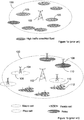
- FIG. 1a In a cellular network, there may be areas with "high traffic", i.e. a high concentration of users.
- An exemplifying cell 100 comprising areas 103 with a high concentration of users is illustrated in figure 1a .
- Capacity could be added in the form of an additional macro base station, generating/serving a cell which covers one or more of the area(s) in need of extra capacity.
- Capacity could also be added in the form of additional nodes with lower output power, as compared to a macro base station, and thus covering a relatively smaller area, to which the desired capacity boost is concentrated.
- One way to achieve a coverage extension is to deploy an additional node, e.g. a node with a low output power, which concentrates the coverage boost to a relatively small area, e.g. where it is most needed.
- Figure 1b illustrates a macro base station 102, which provides a wide area coverage 100 (also called macro cell).
- Figure 1b also shows examples of low power nodes that are deployed to provide small area capacity/coverage.
- pico base stations 104, relays 108 and home base stations 110 (femto cells) are shown.
- a pico base station can either be similar to a macro eNB, but typically with more limited coverage, for example, having a lower max transmission power, or, be a remote radio unit connected to a main unit.
- a common term for such pico/relay/femto cells is "underlay cells", served by "underlay nodes". This type of network deployments are typically referred to as: “Heterogeneous Networks", “multilayer networks” or shortly “HetNets”.
- Underlay cells typically operate at lower reference (pilot/perch) signal powers, as compared to macro cells. This means that if the cell selections as well as mobility decisions are based on received reference signal strengths, the downlink cell border will be located closer to the underlay node than to the macro node/base station/eNB. If the uplink sensitivity for all cells is similar, or if the difference in uplink sensitivity is not equivalent to the difference in reference (pilot/perch) signal powers, then the uplink cell border will be different from the downlink cell border.
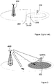
- Figure 2 illustrates a scenario where the uplink 204 and downlink 206 cell borders are separated.
- a situation where the UL and DL borders are separated may be referred to as an uplink/downlink (or downlink/uplink) imbalance in the area between the separated borders.
- This means that a UE in the area between the separated borders will have a better uplink connection to the underlay node 204, but because of the stronger DL transmit power of the macro node 202, it will receive a stronger DL signal from the macro node 202.
- the situation of uplink/downlink imbalance is not limited to macro cell/underlay cell combinations, but may arise also between macro cells and in locations with unfavorable radio conditions, e.g. in urban environments.
- a first UE served by the macro node 202 may cause significant uplink interference to the underlay node 204 if located in an area relatively close to the underlay node. In fact, if located in the area with uplink/downlink imbalance, said UE may even have the best uplink to the underlay node/cell, but might nonetheless not have detected the underlay cell reference signal.
- One way to relieve this situation of significant interference to the underlay node is to consider an underlay cell range expansions by considering offsets in the cell selection and/or mobility decisions. Thereby, potentially interfering UEs served by the macro node will be at a longer distance away from the underlay node, and thereby induce less interference to the underlay node. However, this also means that some UEs served by the underlay node can be subjected to critical interference from the macro node in the downlink.
- relaying support was added in the Rel-10 version of 3GPP LTE specification.
- the relay solution described in Rel-10 is a so-called "layer 3 relay", which means that all radio protocols (layers 1-3) are terminated in the Relay Node (RN).
- UEs connect to the RN over standard Uu interface, meaning that backwards compatibility with Rel-8 UEs is achieved. From a UE perspective, the RN looks like an ordinary eNB.
- the RN has no fixed backhaul, but connects wirelessly to a donor cell using the Un interface.
- the donor cell is controlled by a donor eNB and is based on Uu protocols, with some modifications.
- the donor eNB also serves UEs connected directly to the donor eNB.
- inband relays operate in the same frequencies as the macro layer (i.e. same as the donor node), which implies that the same frequency range is used on the access link and backhaul link.
- One issue with these relays is the uplink/downlink imbalance problem, which comes from the fact that the relay uses a lower transmit power than the macro eNBs, as described above and illustrated in figure 2 . Because of its lower transmit power, the size of the relay cell, when measured based on downlink Reference Symbol Received Power (RSRP), is smaller than the macro cell. Still, when considering uplink transmissions, UEs connected to the macro cell and located close to the relay cell may cause interference to UEs connected to the relay cell, as previously mentioned.
- RSRP downlink Reference Symbol Received Power
- One solution to the uplink/downlink imbalance problem is to base the cell selection on UE measured path loss, instead of RSRP.
- the relay cell size is effectively increased (cell range extension), so that all UEs that have a better uplink to the relay connect to it.
- an offset to the RSRP measurement can be used to increase the cell size of the relay cell.
- Users in cell range extension will then suffer from downlink interference from the macro eNB transmitting at higher power than the relay node.
- This situation needs to be solved by coordinating downlink transmissions between the macro and the relay cells in either frequency or time domain. Solutions for this were introduced in Rel-10, e.g. Carrier Aggregation can be used in frequency domain, and Almost Blank Subframes in time domain.
- FIG 3 illustrates an uplink only relay, UORN, associated with a donor eNB.
- the UORN is further associated with an uplink relay area, 302, in which area UEs may be served in the uplink by the UORN and in the downlink by the eNB.
- the downlink would still be received from the (macro) eNB.
- Such an uplink only relay would terminate only layer 2 protocols, i.e. up to MAC layer.
- layer 2 relay nodes were discussed during early phases of the Rel-10 standardization, but were abandoned in favor of the layer 3 relay described above.
- US 2010/022184 A1 (KHOSHNEVIS AHMED [US] ET AL) 28 January 2010 (2010-01-28) discloses a method for selective transmission by a relay node based on channel quality information where the channel quality information is compared to a threshold.
- US2009/0175214 A1 discloses a relay node that monitors the communication between a UE and a base station as well as channel metrics they report to each other. The relay node compares these metrics to its own observations of the relative channels and determines which UEs would benefit from communicating indirectly through itself. The relay node then manages the indirect connection setup.
- NORTEL NETWORKS: "Transparent Relay for LTE-Advanced FDD", 3GPP DRAFT R1-082517 discloses the general concept of an UORN.
- a method is provided in an Uplink-Only Relay Node, UORN, associated with a donor network node.
- the donor network node is assumed to serve a cell in a cellular communication system.
- the method is suitable for supporting connection of a UE in the cell to the UORN for uplink communication.
- the method comprises monitoring a relation, in terms of performance, between a direct uplink communication from the UE to the donor network node, and a potential relayed uplink communication from the UE to the donor network node via the UORN.
- the method further comprises indicating to the eNB when the relation fulfills a condition.
- an UORN is provided.
- the UORN is operable to being associated with a donor network node, where said donor network node serves a cell in a cellular communication system.
- the UORN is suitable for supporting connection of a UE in the cell to the UORN for uplink communication.
- the UORN comprises processing circuitry which is configured to monitor a relation, in terms of performance, between a direct uplink communication from the UE to the donor network node, and a potential relayed uplink communication from the UE to the donor network node via the UORN.
- the processing circuitry is further configured to indicate to the donor network node when the relation fulfills a condition.
- a method is provided in a donor network node.
- the donor network node is assumed to be associated with an UORN.
- the method is suitable for supporting connection of a UE in the cell to the UORN for uplink communication with the donor network node.
- the method comprises receiving information, from the UORN, indicating the identity of a monitored UE for which a condition is fulfilled.
- the condition is related to a relation, in terms of performance, between a direct uplink communication from the UE to the donor network node, and a potential uplink communication relayed via the UORN. If the UE is to be relayed, the method further comprises indicating, to the UORN, that the UE will be relayed via the UORN; and further comprises: adjusting uplink link adaptation of the UE based on the received information.
- a network node operable to serve one or more cells in a cellular communication system.
- the network node is further operable to being a donor network node associated with an UORN.
- the network node is suitable for supporting connection of a UE in the cell to the UORN for uplink communication with the network node.
- the network node comprises processing circuitry configured to receive information, from the UORN, indicating a monitored UE for which a condition is fulfilled.
- the condition is related to a relation, in terms of performance, between a direct uplink communication to the network node, and a potential uplink communication relayed via the UORN.
- the processing circuitry is further configured to, if the UE is to be relayed, indicate to the UORN that the UE will be relayed via the UORN, and further to adjust uplink link adaptation of the UE based on the received information.
- the methods and nodes described above may be used for effectively selecting which UEs to route via an uplink only relay.
- the monitoring may involve reading a grant for uplink communication, which is sent from the donor network node to the UE.
- the monitoring may further involve determining a received signal quality of an uplink transmission corresponding to the read grant.
- the monitoring may alternatively or in addition involve determining a received signal quality of channel sounding reference signals of the UE.
- the received signal quality may be determined in terms of e.g. Signal to Noise Ratio, SNR; Eb/N0; Block Error Rate, BLER; and/or Bit Error Rate, BER.
- the condition may relate to that the determined received signal quality would support a transport block size being larger for the potential relayed uplink than the transport block size used on the direct uplink.
- the condition may relate to that the determined received signal quality would support a transport block size on the potential relayed uplink which is twice the size of the transport block size used in the direct uplink.
- the UE of which the relation is to be monitored may be selected, in the UORN, based on e.g. a UE indicator received from the donor network node and/or the PDCCH format of grants for uplink transmission, sent from the donor network node to the UE.
- the method in the UORN may comprise receiving information from the donor network node, regarding a UE, of which the uplink communication with the donor network node is to be relayed via the UORN. For example, this information could come in response to an indication sent to the donor network node, indicating that the condition is fulfilled for the UE.
- the method in the UORN may also comprise relaying uplink communication from the UE to the donor network node, according to the received information.
- reports may be received, by the network node, from a UE in the cell.
- the reports may relate to a received power of reference signals received by the UE. It may be determined, in the network node, based on the reports, whether the UE is a candidate for being relayed in the uplink by the UORN. If/when it is determined that the UE is a candidate for being relayed, the identity of the UE may be indicated to the UORN (by the network node) for monitoring. It could even be determined in the network node, e.g. based on the reports, whether the UE is to be relayed in the uplink by the UORN.
- the reports received by the network node may be related to received power of reference signals sent from the network node, and possibly also to the received power of reference signals sent from neighboring network nodes (other than the donor network node).
- the determining of whether a UE is a candidate for being monitored may involve comparing information comprised in the reports to a threshold and/or to a reference pattern related to signals received from at least two different network nodes.
- the reference pattern may reflect a position of the UE in relation to the donor network node and at least one other network node.
- the threshold may reflect a position of the UE in relation to the donor network node.
- the indicating, to the UORN, of that the UE will be relayed via the UORN may involve an indicator implying that grants for uplink communication related to the UE are to be monitored by the UORN.
- relay refers to uplink only relay if not otherwise stated.
- donor network node will be used as referring to a network node, such as an eNB, operable to be associated with a relay.
- intercepting is used as meaning reading and/or performing measurements and/or other operations on a message or transmission which is intended for or destined to another node (than the intercepting node). The node(s) for which the transmission was intended will also receive the transmission.
- uplink grants are transmitted on the Physical Downlink Control Channel (PDCCH).
- UEs are addressed by a UE specific identifier, the Radio Network Temporary Identifier (RNTI).
- the RNTI is masked with an error checksum (CRC) which is appended to each grant.
- CRC error checksum
- a UE can determine both that the grant is received intact and that it is the right receiver.
- the uplink grant contains information on which uplink resources, coding, transport block size, etc., that the UE shall use for the uplink transmission.
- the relay by reading (intercepting) an uplink grant from the donor network node, the relay is able to acquire information related to the link quality between a UE and the donor network node. This could be performed by determining (by reading the grant) link adaptation parameters chosen by the donor network node for the UE, since the link adaptation parameters are selected based on the link quality between the UE and the donor network node. Further, the relay could, based on information comprised in the intercepted grant, determine the received quality, e.g. received Signal to Noise Ratio (SNR) e.g. of the corresponding uplink transmission from the UE.
- SNR Signal to Noise Ratio
- the relay By comparing i) the information on the quality of the link between the UE and the donor network node, and ii) the information on the quality of the link between the UE and the relay, with each other, the relay would be able to determine whether the link between the relay and the UE (plus the link between the relay and the donor network node) is better than the link between the UE and the donor network node. If the link between the relay and the UE (plus the link between the relay and the donor network node) is found to be better, the relay may inform the donor network node of this situation, so that the donor network node can ensure that data is routed via the relay when adequate. This scheme will be further described below.
- the donor network node and relay share the same uplink resources, which means that all traffic routed via the relay must be transmitted twice in the same resource space.
- uplink data should preferably only be routed via the relay if the link between the UE and the relay, and the link between the relay and the donor network node, together, require less resources than the direct link between the UE and the donor network node.
- Resources in this case are frequency (Resource Blocks) and time (subframes).
- traffic should be routed via the relay as soon as a larger transport block size can be supported.
- Reading all grants from a donor network node may be a cumbersome task for a relay. Therefore, the relay could in a specific embodiment be configured to monitor e.g. only grants with PDCCH format 2 or 3, which are the formats used for UEs in poor coverage areas.
- PDCCH format 2 or 3 are the formats used for UEs in poor coverage areas.
- the UEs for which PDCCH format 2 or 3 are used are also likely to have a poor uplink to the donor network node. Thus, these UEs are good candidates for having their uplink routed via the relay.
- Another way to limit the number of grants or RNTIs to be monitored by the relay is to configure the donor network node to send a record or list of RNTIs that the relay shall monitor.
- a record or list could comprise all UEs connected to the donor network node, or a subset of these UEs, selected based on some criterion.
- the donor network node could use pathloss estimates to create a subset of UEs.
- the donor network node estimates the pathloss based on knowledge about the transmitted power and on RSRP measurement report sent by the UEs, which RSRP measurements refer to the link between the UE and the donor network node.
- a UE may e.g.
- the donor network node could determine the subset of UEs to be monitored by a relay based on RSRP measurement from the UE including measurements of one or more other neighboring macro cells/network nodes (other than the serving (donor) network node).
- the donor network node could identify or form a reference pattern or fingerprint of UEs that are good candidates for being monitored by the UL only relay.
- UEs that may be good candidates for being relayed or monitored by the relay may be identified based on the relation between, or the respective values of, the reported RSRP measurements for different neighboring network nodes from said UEs.
- the donor network node Once the donor network node has determined that it would be beneficial to route the uplink data from the UE via the relay, it can inform the relay of the identity (RNTI) of the UEs whose uplink will be routed via the relay.
- the actual data transmission via relay can take e.g. the following steps:
- the donor network node creates one "to be monitored" UE subset for each relay.
- the donor network node creates UE subsets associated with only one relay, but also UE subsets associated with two or more relays. For instance, a UE may be equally close to the donor network node and two different relays.
- two or more relays detect and intercept the scheduling information sent by the donor network node and receive/intercept the corresponding uplink transmission, as previously described.
- the donor network node schedules all the relays associated with a UE to forward the data received from this UE.
- the donor network node sorts the relays in decreasing probability of a correct reception and schedules the relays in this order until the data from the UE is correctly received.
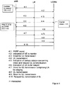
- Figure 4 illustrates signaling, according to an exemplifying embodiment, between donor network node in form of an eNB; an UORN associated with the eNB and a UE.
- the UE is initially only served by the eNB, both in the uplink and the downlink.
- the UE sends an RSRP-report 4:1 to the eNB, which relates to reference signals received from the eNB.
- the eNB analyzes the report and determines whether the UE is a candidate for relaying. If the UE is found to be a candidate for relaying, the eNB sends an indication 4:2 to the UORN, implying that the UE is to be monitored.
- the eNB sends a grant for uplink communication 4:3 to the UE, which is intercepted 4:3i by the UORN. Thereafter, the UE sends the granted uplink communication 4:4 to the eNB, which communication is also intercepted 4:4i by the UORN.
- the UORN sends an indication 4:5 of the determined relation to the eNB. The indication further comprises information on the link between the UE and the UORN. If the UE is to be relayed via the UORN, the identity of the UE is indicated 4:6 to the UORN.
- the eNB sends a grant for uplink communication 4:7 to the UE, which grant comprises information on link adaptation parameters, which are determined based on the link between the UE and the UORN.
- the grant is intercepted 4:7i by the UORN, which then may receive the uplink communication 4:8 corresponding to the grant 4:7.
- the eNB sends a grant for uplink communication 4:9 to the UORN, i.e. schedules the second part/transmission of the relaying.
- the UORN relays 4:10 the uplink communication 4:8 of the UE to the eNB. 4:7-4:10 then repeats until the relaying is interrupted.
- the Uplink-Only Relay Node UORN
- the donor network node is assumed to serve a cell in a cellular communication system, such as an LTE or LTE-A system.
- the methods and nodes described below are suitable for supporting connection of a UE in the cell to the UORN for uplink communication.
- a relation, in terms of performance, between a direct uplink communication from the UE to the donor network node, and a potential relayed uplink communication from the UE to the donor network node (via the UORN) is monitored in an action 404.
- the UE could be monitored simply for the reason that it is present in the cell, e.g. when all UEs in the cell are to be monitored.
- the UE could be selected for monitoring based on information or rules.
- an instruction or indication could be received from the donor network node in an action 402, comprising instructions or an indication of which UE or UEs to monitor, e.g. in form of a list or record.
- Such a record could in some embodiments comprise, e.g. a range of RNTIs.
- the UORN may be provided with a set of rules, e.g. during initialization, of which UEs to monitor, e.g. UEs for which a certain PDCCH format is used for uplink grants.
- rules or information could also be provided by the donor network node.
- the monitoring may involve reading a grant for uplink communication, which is sent from the donor network node to the UE.
- the monitoring may further involve determining a received signal quality, of an uplink transmission corresponding to the grant. That is, the uplink transmission, which was granted by the intercepted grant, is identified, and the received signal quality (at the UORN) of said uplink transmission is determined. Alternatively or in addition, a received signal quality (at the UORN) of channel sounding reference signals of the UE is determined. Such reference signals are typically transmitted by UEs at certain intervals.
- the received signal quality of either the uplink transmission corresponding to the intercepted grant or of the channel sounding reference signals may be determined in different ways.
- the received signal quality could be determined as one or more of: a Signal to Noise Ratio, SNR; an energy per bit to noise power spectral density ratio, Eb/N0; a Block Error Rate, BLER; and a Bit Error Rate, BER.
- the monitored relation fulfills a condition
- this is indicated or reported to the donor network node in an action 408.
- the indication or report may comprise e.g. the RNTI of the UE in question, and a CQI related to the link between the UE and the UORN, such that the donor network node can make or adjust the link adaptation for the UE according to the link between UE and the UORN.
- the condition may relate to that the potential relayed uplink would support a larger transport block size than the transport block size used on the direct uplink.
- the condition may relate to that the determined received signal quality would support a transport block size on the potential relayed uplink being twice the size of the transport block size of the direct uplink.
- the higher block size should also be supported on the backhaul, i.e. the link from UORN to the donor network node.
- the relation of the UE may continue to be monitored, e.g. at certain intervals.
- the indication, to the donor network node, of that a condition is fulfilled for a certain UE enables the donor network node to take action such that the UE is connected to the UORN and the uplink communication of the UE is relayed via the UORN.
- the donor network node could also determine whether to relay the uplink communication of the UE or not, based on one or more further conditions, which may be unknown to the UORN.
- a condition may relate to information received from UEs, e.g. reports of received reference signal strength.
- an indication or instruction) from the donor network node regarding the UE of which the uplink communication is to be relayed is received (by the UORN) in an action 410.
- the uplink communication of the UE is relayed by the UORN according to the information, e.g. in an action 412.
- the information may comprise an indication of that the UORN shall monitor uplink grants for the UE in question.
- the UORN may receive the uplink transmissions corresponding to the grants, and then relay said uplink transmissions to the donor network node, when being scheduled by the donor network node.
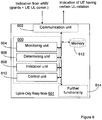
- the UORN is illustrated as to communicate with other entities via a communication unit 602, which may be considered to comprise means for wireless (and possibly wired) uplink communication.
- the transmitter comprised in the communication unit 602 does not need to be as powerful as in a regular relay which communicates with UEs in the downlink.
- the parts of the network node which are adapted to enable the performance of the above described procedure are illustrated as an arrangement 600, surrounded by a dashed line.
- the arrangement and/or UORN may further comprise other functional units 614, for providing e.g. remaining regular relay functions.
- the arrangement and/or node may further comprise one or more storage units 612.
- the arrangement 600 could be implemented by processing circuitry, e.g. by one or more of: a processor or a micro processor and adequate software (and storage therefore), a Programmable Logic Device (PLD) or other electronic component(s)/processing circuit(s) configured to perform the actions mentioned above in conjunction with figures 5a and 5b .
- processing circuitry e.g. by one or more of: a processor or a micro processor and adequate software (and storage therefore), a Programmable Logic Device (PLD) or other electronic component(s)/processing circuit(s) configured to perform the actions mentioned above in conjunction with figures 5a and 5b .
- PLD Programmable Logic Device
- the arrangement 600 may be implemented and described as follows:
- the arrangement 600 may comprise a monitoring unit 604, adapted to monitor a relation, in terms of performance, between a direct uplink communication from the UE to the donor network node, and a potential relayed uplink communication from the UE to the donor network node via the UORN.
- the arrangement 600 further comprises an indication unit 608, which is adapted to indicate to the donor network node when the relation fulfills a condition.
- the determining of whether a condition is fulfilled may be considered as part of the monitoring, or be performed in a determining unit 606, which is adapted therefore.
- the monitoring unit 604 may be adapted to read a grant for uplink communication, which is sent from the donor network node to the UE.
- the monitoring unit may further be adapted to determine a received signal quality, of an uplink transmission corresponding to the grant.
- the monitoring unit may be adapted to determine a received signal quality of channel sounding reference signals of the UE.
- the received signal quality may in both cases be determined e.g. as a Signal to Noise Ratio, SNR; an energy per bit to noise power spectral density ratio, Eb/N0; a Block Error Rate, BLER; and/or a Bit Error Rate, BER.
- the monitoring unit 604 may be adapted to receive instructions from the donor network node regarding which UEs to monitor, as described above.
- the UORN could be provided with a set of rules for monitoring, e.g. at setup.
- the arrangement 600 may further comprise a control unit, adapted to receive information from the donor network node, regarding a UE, of which the uplink communication with the donor network node is to be relayed via/by the UORN; and further adapted to relay the uplink communication from the UE to the donor network node according to the information, as described above.
- the donor network node may be an eNB in an LTE type system.
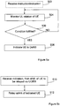
- Figure 7 is divided by a line marked "C". Above the line “C”, actions of an exemplifying procedure for determining which UEs that should be monitored by the UORN, are illustrated. Below the line “C”, actions of an exemplifying procedure for relaying of a UE which has been indicated as suitable for relaying by the UORN, are illustrated. However, the two procedures may be related, as indicated by the broken lines crossing the line “C”. The procedures are further related in that the input to the procedure below line “C” may be a consequence of actions in the procedure above the line.
- information is received from the UORN in an action 708.
- the information indicates a monitored UE for which a condition is fulfilled, where the condition is related to a relation, in terms of performance, between a direct uplink communication from the UE to the donor network node, and a potential uplink communication relayed via/by the UORN.
- it may be determined in an action 710 whether the UE should be relayed or not, given the information that the condition is fulfilled.
- the determining may be based e.g. on rules or conditions which are unknown to the UORN. Alternatively, no such determining is performed, and the indication received from the UORN is enough for that the UE should be relayed. If it is determined in an action 710 that the UE should not, at least not for the moment, be relayed via the UORN, the procedure may e.g. be ended.
- the UE is to be relayed, this is indicated to the UORN in an action 712.
- the indicating may involve identifying the UE to the UORN, e.g. by sending the UE RNTI to the UORN.
- the uplink link adaptation of the UE may be adjusted based on the information received from the UORN in action 708.
- the adjusted link adaptation could be indicated to the UE e.g. in a grant for uplink communication (which could be intercepted by the UORN, thus enabling the UORN to receive the uplink transmission, which is to be relayed).
- the indication to the UORN of that the UE should be relayed could involve or comprise an indicator implying that grants for uplink communication related to the UE are to be monitored by the UORN with the purpose of identifying the corresponding uplink transmissions and relaying the same.
- an action 716 of scheduling the UE and UORN for relaying.
- one or more reports are received from a UE, in an action 702, the report(s) indicating an RSRP of reference signals received by the UE.
- the reference signals concerned by the report may be received by the UE from the donor network node and further from other neighboring network nodes.
- it may be determined in an action 704 whether the UE is a candidate for being relayed in the uplink by the UORN associated with the donor network node.
- the identity of said UE is indicated to the UORN, in an action 706, for monitoring.
- the indication may comprise e.g. an RNTI of the UE to be monitored.
- the donor network node may provide a list or record comprising e.g. RNTIs of UEs to be monitored to the UORN.
- the determining in action 704 may involve comparing of information comprised in the reports to a threshold and/or to a fingerprint.
- fingerprint is here meant a reference pattern or a template related to signals received by a UE from more than one node, i.e. the (serving) donor network node and/or one or more other neighboring network nodes.
- a fingerprint or reference pattern reflects a position of the UE in relation to the (serving) donor network node and the one or more neighbor network nodes.
- a threshold e.g. related to RSRP of signals received from the (serving) donor network node, reflects a position of the UE in relation to said donor network node.
- the comparison to such a threshold and/or fingerprint enables the donor network node to determine whether the UE may be suitable for relaying.
- the comparison may even enable determining that the UE is located in a position where it would benefit from being relayed. In such a situation, it may be decided directly, e.g. in action 704, that the UE should be relayed (and not only monitored), by the UORN. This possibility is indicated in figure 7 by a broken line from the upper part to the lower part of the figure.
- the network node is operable to serve a cell in a cellular communication system, and further operable to being a donor network node associated with an UORN.
- the network node may be an eNB in an LTE type system.
- the network node is illustrated as to communicate with other entities via a communication unit 802, which may be considered to comprise means for wireless (and possibly wired) communication.
- the parts of the network node which are adapted to enable the performance of the above described procedure are illustrated as an arrangement 800, surrounded by a dashed line.
- the arrangement and/or network node may further comprise other functional units 814, for providing e.g. regular network node functions, such as e.g. serving mobile terminals.
- the arrangement and/or network node may further comprise one or more storage units 812.
- the arrangement 800 could be implemented by processing circuitry, e.g. by one or more of: a processor or a micro processor and adequate software (and storage therefore), a Programmable Logic Device (PLD) or other electronic component(s)/processing circuit(s) configured to perform the actions mentioned above in conjunction with figure 7 .
- processing circuitry e.g. by one or more of: a processor or a micro processor and adequate software (and storage therefore), a Programmable Logic Device (PLD) or other electronic component(s)/processing circuit(s) configured to perform the actions mentioned above in conjunction with figure 7 .
- PLD Programmable Logic Device
- the arrangement 800 may be implemented and described as follows:
- the arrangement 800 may comprise a receiving unit 804, adapted to receive information, from the UORN, indicating a monitored UE for which a condition is fulfilled, as previously described.
- the arrangement 800 may further comprise a determining unit 806, adapted to determine whether the indicated UE should be relayed via the UORN.
- the arrangement 800 further comprises an indication unit 808, which is adapted to indicate to the UORN that the UE will be relayed via the UORN (when that is the case).
- the arrangement 800 further comprises a control unit 810, adapted to adjust uplink link adaptation of the UE based on the received information.
- the determining unit 806 may further be adapted to determine whether a UE is a candidate for being relayed in the uplink by the UORN, based on reports received from the UE, as previously described.
- the indicating unit 808 may further be adapted to indicate the UE to the UORN for monitoring when it is determined that the UE is a candidate for being relayed e.g. according to a previously described procedure.
- the control unit may further be adapted to control e.g. the correlated scheduling of the UE and the UORN during the relaying.
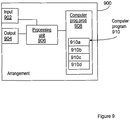
- Figure 9 schematically shows an embodiment of an arrangement 900 in a network node, which also can be an alternative way of disclosing an embodiment of the arrangement in a network node illustrated in figure 6 .
- a processing unit 906 e.g. with a DSP (Digital Signal Processor).
- the processing unit 906 may be a single unit or a plurality of units to perform different actions of procedures described herein.
- the arrangement 900 may also comprise an input unit 902 for receiving signals from other entities, and an output unit 904 for providing signal(s) to other entities.
- the input unit 902 and the output unit 904 may be arranged as an integrated entity.
- the arrangement 900 comprises at least one computer program product 908 in the form of a non-volatile memory, e.g. an EEPROM (Electrically Erasable Programmable Read-Only Memory), a flash memory and a hard drive.
- the computer program product 908 comprises a computer program 910, which comprises code means, which when executed in the processing unit 906 in the arrangement 900 causes the arrangement and/or the network node to perform the actions e.g. of the procedure described earlier in conjunction with figure 5a and 5b .
- the computer program 910 may be configured as a computer program code structured in computer program modules.
- the code means in the computer program 910 of the arrangement 900 may comprise a monitoring module 910a for monitoring a relation, in terms of performance, between a direct uplink communication and a potential relayed uplink communication.
- the computer program may further comprise a determining module 910b for determining whether the monitored relation fulfills a condition.
- the computer program 910 further may further comprise an indication module 910c for indicating, to another network node, when the relation fulfills a condition.
- the computer program 910 may further comprise a control module 910d, for controlling e.g. relaying of the uplink communication according to information received from a/the other network node.
- the computer program may further comprise additional modules, e.g. for providing other desired functionality.
- the modules 910a-d could essentially perform the actions of the flows illustrated in figures 5a and 5b , to emulate the arrangement in a network node illustrated in figure 6 .
- the different modules 910a-d when executed in the processing unit 906, they may correspond to the units 604-610 of figure 6 .
- code means in the embodiment disclosed above in conjunction with figure 9 are implemented as computer program modules which when executed in the processing unit causes the arrangement and/or network node to perform the actions described above in the conjunction with figures mentioned above, at least one of the code means may in alternative embodiments be implemented at least partly as hardware circuits.
- the processor may be a single CPU (Central processing unit), but could also comprise two or more processing units.
- the processor may include general purpose microprocessors; instruction set processors and/or related chips sets and/or special purpose microprocessors such as ASICs (Application Specific Integrated Circuit).
- the processor may also comprise board memory for caching purposes.
- the computer program may be carried by a computer program product connected to the processor.
- the computer program product may comprise a computer readable medium on which the computer program is stored.
- the computer program product may be a flash memory, a RAM (Random-access memory) ROM (Read-Only Memory) or an EEPROM, and the computer program modules described above could in alternative embodiments be distributed on different computer program products in the form of memories within the network node.
Landscapes
- Engineering & Computer Science (AREA)
- Computer Networks & Wireless Communication (AREA)
- Signal Processing (AREA)
- Mobile Radio Communication Systems (AREA)
- Data Exchanges In Wide-Area Networks (AREA)
Applications Claiming Priority (1)
| Application Number | Priority Date | Filing Date | Title |
|---|---|---|---|
| PCT/SE2012/050033 WO2013109171A1 (en) | 2012-01-16 | 2012-01-16 | Method and arrangement for relaying |
Publications (2)
| Publication Number | Publication Date |
|---|---|
| EP2810506A1 EP2810506A1 (en) | 2014-12-10 |
| EP2810506B1 true EP2810506B1 (en) | 2017-12-06 |
Family
ID=45567086
Family Applications (1)
| Application Number | Title | Priority Date | Filing Date |
|---|---|---|---|
| EP12702898.3A Active EP2810506B1 (en) | 2012-01-16 | 2012-01-16 | Method and arrangement for relaying |
Country Status (4)
| Country | Link |
|---|---|
| US (1) | US10506450B2 (enExample) |
| EP (1) | EP2810506B1 (enExample) |
| IN (1) | IN2014CN04643A (enExample) |
| WO (1) | WO2013109171A1 (enExample) |
Families Citing this family (5)
| Publication number | Priority date | Publication date | Assignee | Title |
|---|---|---|---|---|
| US10212651B2 (en) * | 2015-05-14 | 2019-02-19 | Qualcomm Incorporated | Systems, methods, and devices for link quality based relay selection |
| US10361769B2 (en) | 2015-11-18 | 2019-07-23 | Kyocera Corporation | Partial decode and forward (PDF) signal forwarding device with scheduler |
| US20170164252A1 (en) * | 2015-12-04 | 2017-06-08 | Wipro Limited | Methods and Systems for Coordination Multi Point Set Determination for a Wireless Network |
| US11425766B2 (en) * | 2020-03-27 | 2022-08-23 | Qualcomm Incorporated | Determining a link association for a device |
| EP4388796A1 (en) * | 2021-08-17 | 2024-06-26 | Qualcomm Incorporated | Power control for reference signal in uplink dense deployment |
Family Cites Families (45)
| Publication number | Priority date | Publication date | Assignee | Title |
|---|---|---|---|---|
| SE0303602D0 (sv) * | 2003-12-30 | 2003-12-30 | Ericsson Telefon Ab L M | Method and arrangement in self-organizing cooperative network |
| WO2005115022A2 (en) * | 2004-05-13 | 2005-12-01 | Widefi, Inc. | Non-frequency translating repeater with detection and media access control |
| EP1852986B1 (en) * | 2005-03-14 | 2013-01-16 | Panasonic Corporation | Wireless communication system |
| WO2006104105A1 (ja) * | 2005-03-29 | 2006-10-05 | Matsushita Electric Industrial Co., Ltd. | 通信システム、通信中継装置、および通信中継方法 |
| EP1734666A1 (en) * | 2005-06-17 | 2006-12-20 | Fujitsu Limited | Resource management in multi-hop communication system |
| US8660035B2 (en) * | 2005-11-10 | 2014-02-25 | Apple, Inc. | Wireless relay network media access control layer control plane system and method |
| US8284709B2 (en) * | 2005-11-11 | 2012-10-09 | Lg Electronics Inc. | Method of controlling relay communication |
| KR100872420B1 (ko) * | 2005-12-29 | 2008-12-05 | 삼성전자주식회사 | 다중 홉 릴레이 방식을 사용하는 광대역 무선 접속 통신시스템에서 단말에게 투명성 있는 릴레이 서비스를제공하기 위한 장치 및 방법 |
| GB0616476D0 (en) * | 2006-08-18 | 2006-09-27 | Fujitsu Ltd | Communication systems |
| KR101505357B1 (ko) * | 2007-03-07 | 2015-03-23 | 인터디지탈 테크날러지 코포레이션 | 이동국의 업링크 전력 스펙트럼 밀도를 제어하고 셀간 간섭을 완화하기 위한 결합형 개방 루프/폐쇄 루프 방법 |
| WO2008142837A1 (ja) * | 2007-05-11 | 2008-11-27 | Panasonic Corporation | 無線通信方法および無線通信装置 |
| WO2008156662A1 (en) * | 2007-06-14 | 2008-12-24 | George Mason Intellectual Properties, Inc. | Methods of diagnosing non-alcoholic steatohepatitis (nash) |
| KR101046697B1 (ko) * | 2007-08-03 | 2011-07-05 | 삼성전자주식회사 | 중계기를 기반으로 하는 이동통신 시스템에서 피어투피어통신을 위한 자원할당 방법 및 장치 |
| CN102017737B (zh) * | 2007-08-24 | 2014-08-06 | 黑莓有限公司 | 无线网络中中继站上的功率控制 |
| US7907540B2 (en) * | 2007-12-18 | 2011-03-15 | Intel Corporation | Relays in wireless communication networks |
| JP5491412B2 (ja) * | 2008-01-02 | 2014-05-14 | インターデイジタル テクノロジー コーポレーション | 協調無線通信(cooperativewirelesscommunications)のための方法および装置 |
| WO2009101817A1 (ja) * | 2008-02-14 | 2009-08-20 | Panasonic Corporation | 無線通信中継局装置、無線通信基地局装置、無線通信システム及び無線通信方法 |
| US8412182B2 (en) * | 2008-03-20 | 2013-04-02 | Telefonaktiebolaget L M Ericsson (Publ) | Scheduling of uplink measurement reports |
| JP4769834B2 (ja) * | 2008-03-27 | 2011-09-07 | 京セラ株式会社 | 無線通信システム、無線通信装置および無線通信方法 |
| US8331280B2 (en) * | 2008-05-30 | 2012-12-11 | Nokia Corporation | Method, apparatus and computer program for relay selection |
| US20100022184A1 (en) | 2008-07-22 | 2010-01-28 | Sharp Laboratories Of America, Inc. | Systems and methods for selective relaying in wireless networks |
| KR20100035088A (ko) * | 2008-09-25 | 2010-04-02 | 한국전자통신연구원 | 협력 통신 방법 및 그 기지국 |
| EP2348648A4 (en) * | 2008-10-14 | 2015-02-11 | Fujitsu Ltd | RELAY DEVICE, RELAY METHOD AND RELAY PROGRAM |
| US8902805B2 (en) * | 2008-10-24 | 2014-12-02 | Qualcomm Incorporated | Cell relay packet routing |
| CN102204400A (zh) * | 2009-01-06 | 2011-09-28 | 上海贝尔股份有限公司 | 用于实现中继的基站、中继站、移动终端及相应方法 |
| CN101795169A (zh) * | 2009-02-02 | 2010-08-04 | 夏普株式会社 | 中继协助通信系统及其方法 |
| CN101867964B (zh) * | 2009-04-17 | 2012-10-31 | 电信科学技术研究院 | 一种确定协作传输节点的方法及系统、装置 |
| CN102428722A (zh) * | 2009-05-19 | 2012-04-25 | 富士通株式会社 | 基站、中继站、通信系统以及通信方法 |
| EP2443890B1 (en) * | 2009-06-19 | 2018-12-26 | BlackBerry Limited | Type ii relay node initialization procedures |
| CN101965004A (zh) * | 2009-07-21 | 2011-02-02 | 中兴通讯股份有限公司 | 一种用户终端归属节点的选择方法及系统 |
| JP5399830B2 (ja) * | 2009-09-09 | 2014-01-29 | 京セラ株式会社 | 無線通信システム、無線基地局、無線中継局及びハンドオーバ制御方法 |
| EP2306665A1 (en) * | 2009-10-02 | 2011-04-06 | Panasonic Corporation | Relay backhaul uplink HARQ protocol |
| CN102598840A (zh) * | 2009-11-02 | 2012-07-18 | 株式会社日立制作所 | 具有中继装置的无线通信系统及中继终端选择方法 |
| CN102598825B (zh) * | 2009-12-22 | 2015-04-29 | 富士通株式会社 | 中继器中的服务质量控制 |
| EP2355579B1 (en) * | 2010-02-09 | 2012-08-22 | Telefonaktiebolaget LM Ericsson (publ) | Optimized handover configuration |
| JP5165709B2 (ja) * | 2010-02-25 | 2013-03-21 | 株式会社エヌ・ティ・ティ・ドコモ | 無線基地局装置及びスケジューリング方法 |
| JP5647697B2 (ja) * | 2010-03-11 | 2015-01-07 | ノキア ソリューションズ アンド ネットワークス オサケユキチュア | 中継強化型アクセスネットワークにおける信号送信の最適化 |
| AU2011241273B2 (en) * | 2010-04-13 | 2014-03-13 | Lg Electronics Inc. | Method and device for receiving downlink signal |
| US9031596B2 (en) * | 2010-04-26 | 2015-05-12 | Nokia Siemens Networks Oy | Connection arrangement in relayed wireless communications |
| CN102281636B (zh) * | 2010-06-12 | 2016-04-13 | 中兴通讯股份有限公司 | 中继链路的物理下行控制信道的资源分配方法及系统 |
| JP5583035B2 (ja) * | 2011-01-06 | 2014-09-03 | 株式会社日立製作所 | 無線システム及び無線通信方法 |
| CN102612149B (zh) * | 2011-01-25 | 2014-12-03 | 华为技术有限公司 | 一种中继小区无线资源分配方法及基站、系统 |
| JP5711827B2 (ja) * | 2011-03-03 | 2015-05-07 | テレコム・イタリア・エッセ・ピー・アー | 中継器ノードを持つofdmaワイヤレス・ネットワークのためのリンク・スケジューリング・アルゴリズム |
| EP2740307B1 (en) * | 2011-08-02 | 2016-04-06 | BlackBerry Limited | Hidden node interference issue in a type ii relay network |
| US8660015B2 (en) * | 2011-12-27 | 2014-02-25 | Trueposition, Inc. | Location of mobile devices served by a relay node |
-
2012
- 2012-01-16 IN IN4643CHN2014 patent/IN2014CN04643A/en unknown
- 2012-01-16 US US14/372,352 patent/US10506450B2/en not_active Expired - Fee Related
- 2012-01-16 EP EP12702898.3A patent/EP2810506B1/en active Active
- 2012-01-16 WO PCT/SE2012/050033 patent/WO2013109171A1/en not_active Ceased
Also Published As
| Publication number | Publication date |
|---|---|
| US10506450B2 (en) | 2019-12-10 |
| IN2014CN04643A (enExample) | 2015-09-18 |
| EP2810506A1 (en) | 2014-12-10 |
| WO2013109171A1 (en) | 2013-07-25 |
| US20140334331A1 (en) | 2014-11-13 |
Similar Documents
| Publication | Publication Date | Title |
|---|---|---|
| KR101487114B1 (ko) | 향상된 셀간 간섭 조정 가능 무선 단말기에서의 간섭 측정 | |
| KR101618132B1 (ko) | 무선 통신 시스템에서 측정 방법 및 장치 | |
| JP5379242B2 (ja) | 周波数選択性リピータの動作をサポートするためのueリストの作成およびシグナリング | |
| US8849271B2 (en) | Optimized handover configuration | |
| US9420591B2 (en) | Method and apparatus for reconfiguring control channel in wireless communication system | |
| JP5674958B2 (ja) | 測定シグナリングを伝える方法および装置 | |
| CN102792747B (zh) | 用来在通信系统内配置信道状态信息测量的方法与通信装置 | |
| EP2424126B1 (en) | Method and apparatus for transmitting a reference signal in a relay communication system | |
| JP5451937B2 (ja) | 基地局及びプロセッサ | |
| US9414242B2 (en) | Method and device for measuring interference in wireless communication system | |
| JP5647676B2 (ja) | 無線通信システム、高電力基地局、無線端末、低電力基地局、及び無線通信方法 | |
| US9848392B2 (en) | Radio communication system, high-power base station, low-power base station, and communication control method | |
| US20120087266A1 (en) | Method and apparatus for managing inter-cell interference coordination actions for time-domain partitioned cells | |
| US20110228700A1 (en) | Subframe Allocation for In-Band Relay Nodes | |
| WO2013141544A1 (en) | Method and apparatus for performing measurement in wireless communication system | |
| KR20150035592A (ko) | 무선 통신 시스템에서 하향링크 신호 수신 방법 및 장치 | |
| CN102550105A (zh) | 在无线通信系统中的重选 | |
| CN103220803A (zh) | 进行小区参考信号干扰消除的方法 | |
| EP2810506B1 (en) | Method and arrangement for relaying | |
| EP3180953A1 (en) | Inter-cell interference coordination in heterogeneous networks | |
| WO2019059193A1 (ja) | ユーザ端末及び無線通信方法 | |
| WO2023197095A1 (en) | Network-controllable repeater management | |
| CN101959205B (zh) | 一种中继网络中的上行测量方法及系统 |
Legal Events
| Date | Code | Title | Description |
|---|---|---|---|
| PUAI | Public reference made under article 153(3) epc to a published international application that has entered the european phase |
Free format text: ORIGINAL CODE: 0009012 |
|
| 17P | Request for examination filed |
Effective date: 20140731 |
|
| AK | Designated contracting states |
Kind code of ref document: A1 Designated state(s): AL AT BE BG CH CY CZ DE DK EE ES FI FR GB GR HR HU IE IS IT LI LT LU LV MC MK MT NL NO PL PT RO RS SE SI SK SM TR |
|
| AX | Request for extension of the european patent |
Extension state: BA ME |
|
| DAX | Request for extension of the european patent (deleted) | ||
| 17Q | First examination report despatched |
Effective date: 20170117 |
|
| REG | Reference to a national code |
Ref country code: DE Ref legal event code: R079 Ref document number: 602012040541 Country of ref document: DE Free format text: PREVIOUS MAIN CLASS: H04W0072040000 Ipc: H04W0016260000 |
|
| GRAP | Despatch of communication of intention to grant a patent |
Free format text: ORIGINAL CODE: EPIDOSNIGR1 |
|
| RIC1 | Information provided on ipc code assigned before grant |
Ipc: H04B 7/155 20060101ALI20170614BHEP Ipc: H04W 84/04 20090101ALN20170614BHEP Ipc: H04W 16/26 20090101AFI20170614BHEP |
|
| INTG | Intention to grant announced |
Effective date: 20170719 |
|
| GRAS | Grant fee paid |
Free format text: ORIGINAL CODE: EPIDOSNIGR3 |
|
| GRAA | (expected) grant |
Free format text: ORIGINAL CODE: 0009210 |
|
| AK | Designated contracting states |
Kind code of ref document: B1 Designated state(s): AL AT BE BG CH CY CZ DE DK EE ES FI FR GB GR HR HU IE IS IT LI LT LU LV MC MK MT NL NO PL PT RO RS SE SI SK SM TR |
|
| REG | Reference to a national code |
Ref country code: GB Ref legal event code: FG4D |
|
| REG | Reference to a national code |
Ref country code: AT Ref legal event code: REF Ref document number: 953399 Country of ref document: AT Kind code of ref document: T Effective date: 20171215 Ref country code: CH Ref legal event code: EP |
|
| REG | Reference to a national code |
Ref country code: IE Ref legal event code: FG4D |
|
| REG | Reference to a national code |
Ref country code: DE Ref legal event code: R096 Ref document number: 602012040541 Country of ref document: DE |
|
| REG | Reference to a national code |
Ref country code: NL Ref legal event code: FP |
|
| REG | Reference to a national code |
Ref country code: LT Ref legal event code: MG4D |
|
| PG25 | Lapsed in a contracting state [announced via postgrant information from national office to epo] |
Ref country code: SE Free format text: LAPSE BECAUSE OF FAILURE TO SUBMIT A TRANSLATION OF THE DESCRIPTION OR TO PAY THE FEE WITHIN THE PRESCRIBED TIME-LIMIT Effective date: 20171206 Ref country code: LT Free format text: LAPSE BECAUSE OF FAILURE TO SUBMIT A TRANSLATION OF THE DESCRIPTION OR TO PAY THE FEE WITHIN THE PRESCRIBED TIME-LIMIT Effective date: 20171206 Ref country code: NO Free format text: LAPSE BECAUSE OF FAILURE TO SUBMIT A TRANSLATION OF THE DESCRIPTION OR TO PAY THE FEE WITHIN THE PRESCRIBED TIME-LIMIT Effective date: 20180306 Ref country code: FI Free format text: LAPSE BECAUSE OF FAILURE TO SUBMIT A TRANSLATION OF THE DESCRIPTION OR TO PAY THE FEE WITHIN THE PRESCRIBED TIME-LIMIT Effective date: 20171206 Ref country code: ES Free format text: LAPSE BECAUSE OF FAILURE TO SUBMIT A TRANSLATION OF THE DESCRIPTION OR TO PAY THE FEE WITHIN THE PRESCRIBED TIME-LIMIT Effective date: 20171206 |
|
| REG | Reference to a national code |
Ref country code: AT Ref legal event code: MK05 Ref document number: 953399 Country of ref document: AT Kind code of ref document: T Effective date: 20171206 |
|
| PG25 | Lapsed in a contracting state [announced via postgrant information from national office to epo] |
Ref country code: RS Free format text: LAPSE BECAUSE OF FAILURE TO SUBMIT A TRANSLATION OF THE DESCRIPTION OR TO PAY THE FEE WITHIN THE PRESCRIBED TIME-LIMIT Effective date: 20171206 Ref country code: BG Free format text: LAPSE BECAUSE OF FAILURE TO SUBMIT A TRANSLATION OF THE DESCRIPTION OR TO PAY THE FEE WITHIN THE PRESCRIBED TIME-LIMIT Effective date: 20180306 Ref country code: HR Free format text: LAPSE BECAUSE OF FAILURE TO SUBMIT A TRANSLATION OF THE DESCRIPTION OR TO PAY THE FEE WITHIN THE PRESCRIBED TIME-LIMIT Effective date: 20171206 Ref country code: GR Free format text: LAPSE BECAUSE OF FAILURE TO SUBMIT A TRANSLATION OF THE DESCRIPTION OR TO PAY THE FEE WITHIN THE PRESCRIBED TIME-LIMIT Effective date: 20180307 Ref country code: LV Free format text: LAPSE BECAUSE OF FAILURE TO SUBMIT A TRANSLATION OF THE DESCRIPTION OR TO PAY THE FEE WITHIN THE PRESCRIBED TIME-LIMIT Effective date: 20171206 |
|
| PG25 | Lapsed in a contracting state [announced via postgrant information from national office to epo] |
Ref country code: SK Free format text: LAPSE BECAUSE OF FAILURE TO SUBMIT A TRANSLATION OF THE DESCRIPTION OR TO PAY THE FEE WITHIN THE PRESCRIBED TIME-LIMIT Effective date: 20171206 Ref country code: CZ Free format text: LAPSE BECAUSE OF FAILURE TO SUBMIT A TRANSLATION OF THE DESCRIPTION OR TO PAY THE FEE WITHIN THE PRESCRIBED TIME-LIMIT Effective date: 20171206 Ref country code: EE Free format text: LAPSE BECAUSE OF FAILURE TO SUBMIT A TRANSLATION OF THE DESCRIPTION OR TO PAY THE FEE WITHIN THE PRESCRIBED TIME-LIMIT Effective date: 20171206 |
|
| PG25 | Lapsed in a contracting state [announced via postgrant information from national office to epo] |
Ref country code: PL Free format text: LAPSE BECAUSE OF FAILURE TO SUBMIT A TRANSLATION OF THE DESCRIPTION OR TO PAY THE FEE WITHIN THE PRESCRIBED TIME-LIMIT Effective date: 20171206 Ref country code: RO Free format text: LAPSE BECAUSE OF FAILURE TO SUBMIT A TRANSLATION OF THE DESCRIPTION OR TO PAY THE FEE WITHIN THE PRESCRIBED TIME-LIMIT Effective date: 20171206 Ref country code: AT Free format text: LAPSE BECAUSE OF FAILURE TO SUBMIT A TRANSLATION OF THE DESCRIPTION OR TO PAY THE FEE WITHIN THE PRESCRIBED TIME-LIMIT Effective date: 20171206 Ref country code: IT Free format text: LAPSE BECAUSE OF FAILURE TO SUBMIT A TRANSLATION OF THE DESCRIPTION OR TO PAY THE FEE WITHIN THE PRESCRIBED TIME-LIMIT Effective date: 20171206 Ref country code: SM Free format text: LAPSE BECAUSE OF FAILURE TO SUBMIT A TRANSLATION OF THE DESCRIPTION OR TO PAY THE FEE WITHIN THE PRESCRIBED TIME-LIMIT Effective date: 20171206 |
|
| REG | Reference to a national code |
Ref country code: CH Ref legal event code: PL |
|
| REG | Reference to a national code |
Ref country code: DE Ref legal event code: R097 Ref document number: 602012040541 Country of ref document: DE |
|
| PG25 | Lapsed in a contracting state [announced via postgrant information from national office to epo] |
Ref country code: MC Free format text: LAPSE BECAUSE OF FAILURE TO SUBMIT A TRANSLATION OF THE DESCRIPTION OR TO PAY THE FEE WITHIN THE PRESCRIBED TIME-LIMIT Effective date: 20171206 |
|
| PLBE | No opposition filed within time limit |
Free format text: ORIGINAL CODE: 0009261 |
|
| STAA | Information on the status of an ep patent application or granted ep patent |
Free format text: STATUS: NO OPPOSITION FILED WITHIN TIME LIMIT |
|
| PG25 | Lapsed in a contracting state [announced via postgrant information from national office to epo] |
Ref country code: LU Free format text: LAPSE BECAUSE OF NON-PAYMENT OF DUE FEES Effective date: 20180116 Ref country code: FR Free format text: LAPSE BECAUSE OF NON-PAYMENT OF DUE FEES Effective date: 20180206 |
|
| REG | Reference to a national code |
Ref country code: IE Ref legal event code: MM4A |
|
| REG | Reference to a national code |
Ref country code: FR Ref legal event code: ST Effective date: 20180928 |
|
| REG | Reference to a national code |
Ref country code: BE Ref legal event code: MM Effective date: 20180131 |
|
| 26N | No opposition filed |
Effective date: 20180907 |
|
| PG25 | Lapsed in a contracting state [announced via postgrant information from national office to epo] |
Ref country code: LI Free format text: LAPSE BECAUSE OF NON-PAYMENT OF DUE FEES Effective date: 20180131 Ref country code: SI Free format text: LAPSE BECAUSE OF FAILURE TO SUBMIT A TRANSLATION OF THE DESCRIPTION OR TO PAY THE FEE WITHIN THE PRESCRIBED TIME-LIMIT Effective date: 20171206 Ref country code: BE Free format text: LAPSE BECAUSE OF NON-PAYMENT OF DUE FEES Effective date: 20180131 Ref country code: CH Free format text: LAPSE BECAUSE OF NON-PAYMENT OF DUE FEES Effective date: 20180131 Ref country code: DK Free format text: LAPSE BECAUSE OF FAILURE TO SUBMIT A TRANSLATION OF THE DESCRIPTION OR TO PAY THE FEE WITHIN THE PRESCRIBED TIME-LIMIT Effective date: 20171206 |
|
| PG25 | Lapsed in a contracting state [announced via postgrant information from national office to epo] |
Ref country code: IE Free format text: LAPSE BECAUSE OF NON-PAYMENT OF DUE FEES Effective date: 20180116 |
|
| PG25 | Lapsed in a contracting state [announced via postgrant information from national office to epo] |
Ref country code: MT Free format text: LAPSE BECAUSE OF NON-PAYMENT OF DUE FEES Effective date: 20180116 |
|
| PG25 | Lapsed in a contracting state [announced via postgrant information from national office to epo] |
Ref country code: TR Free format text: LAPSE BECAUSE OF FAILURE TO SUBMIT A TRANSLATION OF THE DESCRIPTION OR TO PAY THE FEE WITHIN THE PRESCRIBED TIME-LIMIT Effective date: 20171206 |
|
| PG25 | Lapsed in a contracting state [announced via postgrant information from national office to epo] |
Ref country code: HU Free format text: LAPSE BECAUSE OF FAILURE TO SUBMIT A TRANSLATION OF THE DESCRIPTION OR TO PAY THE FEE WITHIN THE PRESCRIBED TIME-LIMIT; INVALID AB INITIO Effective date: 20120116 Ref country code: PT Free format text: LAPSE BECAUSE OF FAILURE TO SUBMIT A TRANSLATION OF THE DESCRIPTION OR TO PAY THE FEE WITHIN THE PRESCRIBED TIME-LIMIT Effective date: 20171206 |
|
| PG25 | Lapsed in a contracting state [announced via postgrant information from national office to epo] |
Ref country code: CY Free format text: LAPSE BECAUSE OF FAILURE TO SUBMIT A TRANSLATION OF THE DESCRIPTION OR TO PAY THE FEE WITHIN THE PRESCRIBED TIME-LIMIT Effective date: 20171206 Ref country code: MK Free format text: LAPSE BECAUSE OF NON-PAYMENT OF DUE FEES Effective date: 20171206 |
|
| PG25 | Lapsed in a contracting state [announced via postgrant information from national office to epo] |
Ref country code: AL Free format text: LAPSE BECAUSE OF FAILURE TO SUBMIT A TRANSLATION OF THE DESCRIPTION OR TO PAY THE FEE WITHIN THE PRESCRIBED TIME-LIMIT Effective date: 20171206 Ref country code: IS Free format text: LAPSE BECAUSE OF FAILURE TO SUBMIT A TRANSLATION OF THE DESCRIPTION OR TO PAY THE FEE WITHIN THE PRESCRIBED TIME-LIMIT Effective date: 20180406 |
|
| PGFP | Annual fee paid to national office [announced via postgrant information from national office to epo] |
Ref country code: DE Payment date: 20230127 Year of fee payment: 12 |
|
| PGFP | Annual fee paid to national office [announced via postgrant information from national office to epo] |
Ref country code: NL Payment date: 20230126 Year of fee payment: 12 |
|
| REG | Reference to a national code |
Ref country code: DE Ref legal event code: R119 Ref document number: 602012040541 Country of ref document: DE |
|
| REG | Reference to a national code |
Ref country code: NL Ref legal event code: MM Effective date: 20240201 |
|
| PG25 | Lapsed in a contracting state [announced via postgrant information from national office to epo] |
Ref country code: DE Free format text: LAPSE BECAUSE OF NON-PAYMENT OF DUE FEES Effective date: 20240801 |
|
| PG25 | Lapsed in a contracting state [announced via postgrant information from national office to epo] |
Ref country code: NL Free format text: LAPSE BECAUSE OF NON-PAYMENT OF DUE FEES Effective date: 20240201 |
|
| PG25 | Lapsed in a contracting state [announced via postgrant information from national office to epo] |
Ref country code: NL Free format text: LAPSE BECAUSE OF NON-PAYMENT OF DUE FEES Effective date: 20240201 Ref country code: DE Free format text: LAPSE BECAUSE OF NON-PAYMENT OF DUE FEES Effective date: 20240801 |
|
| PGFP | Annual fee paid to national office [announced via postgrant information from national office to epo] |
Ref country code: GB Payment date: 20250127 Year of fee payment: 14 |