EP2810334B1 - Kommunikationssystem in einer elektrischen batterie - Google Patents
Kommunikationssystem in einer elektrischen batterie Download PDFInfo
- Publication number
- EP2810334B1 EP2810334B1 EP13701097.1A EP13701097A EP2810334B1 EP 2810334 B1 EP2810334 B1 EP 2810334B1 EP 13701097 A EP13701097 A EP 13701097A EP 2810334 B1 EP2810334 B1 EP 2810334B1
- Authority
- EP
- European Patent Office
- Prior art keywords
- nodes
- battery
- terminals
- cells
- alternating signal
- Prior art date
- Legal status (The legal status is an assumption and is not a legal conclusion. Google has not performed a legal analysis and makes no representation as to the accuracy of the status listed.)
- Not-in-force
Links
- 238000004891 communication Methods 0.000 title description 35
- 239000003990 capacitor Substances 0.000 claims description 32
- 238000002955 isolation Methods 0.000 claims description 10
- 230000001939 inductive effect Effects 0.000 claims description 5
- 238000000034 method Methods 0.000 claims description 5
- 238000012545 processing Methods 0.000 claims description 4
- 239000003792 electrolyte Substances 0.000 claims description 3
- 238000010586 diagram Methods 0.000 description 8
- 230000000644 propagated effect Effects 0.000 description 6
- 230000001681 protective effect Effects 0.000 description 3
- 230000006870 function Effects 0.000 description 2
- 238000012986 modification Methods 0.000 description 2
- 230000004048 modification Effects 0.000 description 2
- 238000009529 body temperature measurement Methods 0.000 description 1
- 238000005516 engineering process Methods 0.000 description 1
- 238000004519 manufacturing process Methods 0.000 description 1
- 230000003071 parasitic effect Effects 0.000 description 1
- 230000008685 targeting Effects 0.000 description 1
- 238000012546 transfer Methods 0.000 description 1
- 238000011144 upstream manufacturing Methods 0.000 description 1
Images

Classifications
-
- H—ELECTRICITY
- H04—ELECTRIC COMMUNICATION TECHNIQUE
- H04B—TRANSMISSION
- H04B3/00—Line transmission systems
- H04B3/54—Systems for transmission via power distribution lines
- H04B3/548—Systems for transmission via power distribution lines the power on the line being DC
-
- G—PHYSICS
- G01—MEASURING; TESTING
- G01R—MEASURING ELECTRIC VARIABLES; MEASURING MAGNETIC VARIABLES
- G01R31/00—Arrangements for testing electric properties; Arrangements for locating electric faults; Arrangements for electrical testing characterised by what is being tested not provided for elsewhere
- G01R31/36—Arrangements for testing, measuring or monitoring the electrical condition of accumulators or electric batteries, e.g. capacity or state of charge [SoC]
- G01R31/374—Arrangements for testing, measuring or monitoring the electrical condition of accumulators or electric batteries, e.g. capacity or state of charge [SoC] with means for correcting the measurement for temperature or ageing
-
- H—ELECTRICITY
- H01—ELECTRIC ELEMENTS
- H01M—PROCESSES OR MEANS, e.g. BATTERIES, FOR THE DIRECT CONVERSION OF CHEMICAL ENERGY INTO ELECTRICAL ENERGY
- H01M10/00—Secondary cells; Manufacture thereof
- H01M10/42—Methods or arrangements for servicing or maintenance of secondary cells or secondary half-cells
- H01M10/48—Accumulators combined with arrangements for measuring, testing or indicating the condition of cells, e.g. the level or density of the electrolyte
- H01M10/482—Accumulators combined with arrangements for measuring, testing or indicating the condition of cells, e.g. the level or density of the electrolyte for several batteries or cells simultaneously or sequentially
-
- H—ELECTRICITY
- H02—GENERATION; CONVERSION OR DISTRIBUTION OF ELECTRIC POWER
- H02J—CIRCUIT ARRANGEMENTS OR SYSTEMS FOR SUPPLYING OR DISTRIBUTING ELECTRIC POWER; SYSTEMS FOR STORING ELECTRIC ENERGY
- H02J50/00—Circuit arrangements or systems for wireless supply or distribution of electric power
- H02J50/10—Circuit arrangements or systems for wireless supply or distribution of electric power using inductive coupling
- H02J50/12—Circuit arrangements or systems for wireless supply or distribution of electric power using inductive coupling of the resonant type
-
- H—ELECTRICITY
- H01—ELECTRIC ELEMENTS
- H01M—PROCESSES OR MEANS, e.g. BATTERIES, FOR THE DIRECT CONVERSION OF CHEMICAL ENERGY INTO ELECTRICAL ENERGY
- H01M10/00—Secondary cells; Manufacture thereof
- H01M10/42—Methods or arrangements for servicing or maintenance of secondary cells or secondary half-cells
- H01M10/4207—Methods or arrangements for servicing or maintenance of secondary cells or secondary half-cells for several batteries or cells simultaneously or sequentially
-
- H—ELECTRICITY
- H01—ELECTRIC ELEMENTS
- H01M—PROCESSES OR MEANS, e.g. BATTERIES, FOR THE DIRECT CONVERSION OF CHEMICAL ENERGY INTO ELECTRICAL ENERGY
- H01M10/00—Secondary cells; Manufacture thereof
- H01M10/42—Methods or arrangements for servicing or maintenance of secondary cells or secondary half-cells
- H01M10/48—Accumulators combined with arrangements for measuring, testing or indicating the condition of cells, e.g. the level or density of the electrolyte
- H01M10/486—Accumulators combined with arrangements for measuring, testing or indicating the condition of cells, e.g. the level or density of the electrolyte for measuring temperature
-
- H—ELECTRICITY
- H04—ELECTRIC COMMUNICATION TECHNIQUE
- H04B—TRANSMISSION
- H04B2203/00—Indexing scheme relating to line transmission systems
- H04B2203/54—Aspects of powerline communications not already covered by H04B3/54 and its subgroups
- H04B2203/5429—Applications for powerline communications
- H04B2203/5458—Monitor sensor; Alarm systems
-
- Y—GENERAL TAGGING OF NEW TECHNOLOGICAL DEVELOPMENTS; GENERAL TAGGING OF CROSS-SECTIONAL TECHNOLOGIES SPANNING OVER SEVERAL SECTIONS OF THE IPC; TECHNICAL SUBJECTS COVERED BY FORMER USPC CROSS-REFERENCE ART COLLECTIONS [XRACs] AND DIGESTS
- Y02—TECHNOLOGIES OR APPLICATIONS FOR MITIGATION OR ADAPTATION AGAINST CLIMATE CHANGE
- Y02E—REDUCTION OF GREENHOUSE GAS [GHG] EMISSIONS, RELATED TO ENERGY GENERATION, TRANSMISSION OR DISTRIBUTION
- Y02E60/00—Enabling technologies; Technologies with a potential or indirect contribution to GHG emissions mitigation
- Y02E60/10—Energy storage using batteries
-
- Y—GENERAL TAGGING OF NEW TECHNOLOGICAL DEVELOPMENTS; GENERAL TAGGING OF CROSS-SECTIONAL TECHNOLOGIES SPANNING OVER SEVERAL SECTIONS OF THE IPC; TECHNICAL SUBJECTS COVERED BY FORMER USPC CROSS-REFERENCE ART COLLECTIONS [XRACs] AND DIGESTS
- Y02—TECHNOLOGIES OR APPLICATIONS FOR MITIGATION OR ADAPTATION AGAINST CLIMATE CHANGE
- Y02T—CLIMATE CHANGE MITIGATION TECHNOLOGIES RELATED TO TRANSPORTATION
- Y02T10/00—Road transport of goods or passengers
- Y02T10/60—Other road transportation technologies with climate change mitigation effect
- Y02T10/70—Energy storage systems for electromobility, e.g. batteries
Definitions
- the present invention relates to communications between a master device and one or more slave devices in an electric battery.
- An electric battery is a group of several elementary cells (batteries, accumulators, etc.) connected in series and / or in parallel between two nodes or terminals for supplying a DC voltage.
- the cells of the battery are generally housed in a protective housing leaving only two lugs respectively connected to the two terminals of the battery.
- sensors or other electronic devices located inside the protective case, for example temperature sensors placed on cells of the battery, electronic identification tags, or any other type of device.
- a disadvantage lies in the need to remove cables outside the housing, which involves providing connectors and a risk of tearing.
- the number of cables needed for the instrumentation of a battery can be significant, resulting in a significant increase in the cost price of the battery.
- the cables can pick up electromagnetic disturbances that could to alter the data signals between the master device and the slave devices.
- radio wave non-contact
- an object of an embodiment of the present invention is a communication system between a master device and at least one slave device in an electric battery, this system at least partially overcoming some of the disadvantages of known systems.
- Another object of an embodiment of the present invention is to provide a more reliable communication system than known systems.
- Another object of an embodiment of the present invention is to provide a less expensive communication system than the known systems.
- Another object of an embodiment of the present invention is to provide a method of communication between a master device and one or more slave devices in an electric battery.
- an embodiment of the present invention provides a system comprising: a battery in which a plurality of elementary cells are connected between two first nodes; a first device adapted to apply a alternative signal to the first nodes; at least one second device connected to two second nodes of the plurality of cells; and at least one resonant assembly of which an inductive element comprises the own inductance of the battery between the second nodes.
- the resonant assembly comprises at least one capacitive element of said at least one second device.
- said at least one second device is adapted to communicate with the first device by modulation of said alternative signal seen by the second nodes.
- the resonance frequency of said resonant assembly is approximately equal to the frequency of said alternating signal.
- the resonance frequency of said resonant assembly is between 30 kHz and 30 MHz.
- the second nodes are two power terminals of the same elementary cell.
- the cells of the battery are connected in series between said first nodes.
- the cells of the battery are connected in parallel between the first nodes.
- said at least one second device comprises a processing circuit comprising two third nodes, said at least one second device comprising isolation capacitors between the third nodes and the second nodes.
- the first device comprises an alternating generator and an impedance transformer between said generator and said first nodes.
- the first device comprises frequency tuning capacitors and isolation capacitors between said transformer and said first nodes.
- the present invention also provides an electric battery comprising: a plurality of elementary cells connected between two first nodes; at least one device connected to two second nodes of said plurality of cells; and at least one resonant assembly of which an inductive element comprises the own inductance of the battery between said second nodes.
- said at least one device is adapted to modulate an alternating signal received by the second nodes.
- the resonant assembly comprises at least one capacitive element of said at least one device.
- said at least one device is located inside an elementary cell of the battery.
- said at least one device comprises a sensor capable of measuring the temperature of the electrolyte of the cell.
- the figure 1 is a perspective view schematically showing an example of an embodiment of a communication system between a master device M, or reader, and at least one slave device S in an electric battery 14.
- the battery 14 comprises twelve elementary cells c 1 to c 12 connected in series between terminals V + and V- for supplying a DC voltage.
- the slave device S comprises for example a temperature sensor or an electronic identification tag, and is connected to the terminals of an elementary cell of the battery (cell c 10 in this example) via the two contacts A and B.
- the master device M is connected to the main terminals V + and V- of the battery 14 via two contacts C and D.
- the master device M is adapted to apply an alternating signal on the main terminals V + and V- of the battery, that is to say to emit, on the power path of the battery , an alternating signal superimposed on the DC voltage of the battery.
- the slave device S connected in parallel with a portion of the power path of the battery, is adapted to communicate with the device M by demodulating and / or modulating the AC signal seen on its terminals A and B.
- the slave device S could be housed inside the housing, and the master device M could be located outside the housing, and connected to terminals V + and V-.
- the figure 2 is an electrical diagram illustrating in more detail one embodiment of the slave device S connected to the elementary cell c 10 of the electric battery 14 of the figure 1 .
- the elementary cell c 10 behaves as an inductance Lc 10 in series with a resistor Rc 10 .
- the values of the inductance Lc 10 and the resistance Rc 10 depend, among other factors, on the technology for producing the cell 10 ' of its structure, etc.
- the slave device S forms, with the own inductance Lc 10 and the resistor Rc 10 of the cell c 10 to which it is connected, a resonant assembly.
- the slave device S comprises a main circuit 21 (TAG), or processing circuit, comprising two terminals F and G for applying an alternating signal.
- TAG main circuit 21
- Two isolation (or decoupling) capacitors CI are provided respectively between terminal A and terminal F, and between terminal B and terminal G, to prevent the DC voltage of cell c 10 from being applied to terminals F and G of the circuit 21.
- the circuit 21 therefore sees at its terminals only the alternating signal propagated by the master device M on the power path of the battery.
- CI capacitors possible in particular to prevent the cell c 10 from draining into the circuit 21.
- the S device further comprises a tuning capacitor CA of the resonant frequency of the assembly formed by the device S, the inductance Lc 10 ' and resistor Rc 10 .
- the capacitor CA is connected between the terminals F and G.
- the capacitor CA is for example a capacitor with variable capacitance.
- the AC capacity is chosen according to the frequency of the alternating signal applied by the device M to the terminals V + and V- of the battery, so that the resonant assembly formed by the device and the cell S c 10 resonates at this frequency.
- the alternating signal seen by the circuit 21 on its terminals F and G is an amplified copy of the alternating signal propagated by the master device M on the power path of the battery.
- the resonant frequency of the resonant assembly is essentially a function of the AC capacitance and the Lc 10 inductance.
- the circuit 21 comprises for example a modulation circuit of the AC signal seen at its terminals F and G, allowing it to transmit data to the master device M via the power path of the battery.
- the data transmitted by the circuit 21 may be an identification number contained in a memory of the circuit 21, a temperature measurement made by a sensor of the circuit 21, or any other data.
- the circuit 21 may for example vary its own impedance, resulting in a variation of amplitude of the alternating signal propagated on the power path of the battery. Any other suitable modulation method may however be used (frequency modulation, phase modulation, etc.).
- the circuit 21 may further comprise a demodulation circuit of the alternating signal seen on its terminals F and G, so as to allow two-way communication between the master device M and the slave device S.
- the circuit 21 may comprise a power supply unit (not shown), comprising means for rectifying the AC signal seen terminals F and G and providing a DC voltage rectified across a capacitor. This allows the circuit 21 to draw its electrical power supply not directly in the cell c 10 ' but in the alternating signal emitted by the reader M (it being understood that the reader M can be powered either by the battery 14 or by a external source).
- sensors or other electronic devices adapted to communicate by radio waves with a remote reader, generally according to standardized protocols.
- sensors equipped with an antenna or comprising terminals for connection to an antenna and which already include modulation, demodulation or production circuits for a continuous supply voltage by rectifying an alternating signal. provided by the antenna.
- TAG circuit 21
- the existing device already includes an antenna this antenna is previously removed, otherwise the existing device can be used as is.
- the terminals F and G by which the existing device is connected to the capacitors CI and CA are the terminals normally intended to be connected to an antenna.
- the existing device can be used without further modification since, from the point of view of the sensor, it is irrelevant whether the alternating signal seen on the terminals F and G is propagated from or to the master device by the airs (via an antenna) or by the power path of the battery.
- RFID Radio Frequency Identification
- devices adapted to operate in accordance with a communication protocol described in ISO 15693, normally targeting wireless contactless communication over a carrier frequency at 13.56 MHz may be used.
- the frequency of the alternating signal emitted by the master device M is then set at 13.56 MHz, and the AC tuning capacity of the slave device S is chosen so that the resonance frequency of the resonant assembly comprising the slave device S c and the cell 10 is approximately 13.56 MHz.
- the master device M can be produced from an existing reader comprising an alternating signal generator intended to be connected to an antenna, and means for modulating and / or demodulating transmitted signals and / or or received by the antenna. If the existing player already has an antenna, this antenna is removed beforehand.
- the terminals V + and V- of the battery can be connected instead of the antenna via isolation capacitors or decoupling to prevent the DC voltage of the battery is applied to the reader.
- the described embodiments are of course not limited to the reuse of existing elements of non-contact radio communication systems.
- any working frequency other than 13.56 MHz may be used.
- the inventors have found that the frequencies between 30 kHz and 30 MHz are particularly suitable for the implementation of robust communications via the power path of the battery.
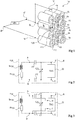
- the figure 3 is an electrical diagram illustrating an alternative embodiment of the slave device S of the figure 2 .
- the device of the figure 3 differs from the device of the figure 2 in that the circuit 21 is powered not by rectifying the alternating signal seen at its terminals F and G, but by a direct voltage taken directly across the cell to which the device S is connected.
- the circuit 21 has terminals H and I for applying a DC supply voltage.
- the terminals H and I are respectively connected to the terminals A and B of the device S, that is to say upstream of the isolation capacitors CI.
- the terminals H and I directly receive the DC voltage delivered by this cell.
- the figure 4 is an electrical diagram illustrating an exemplary embodiment of a communication system between a master device M and slave devices S i in an electric battery in which elementary cells c i are connected in series between terminals V + and V- of the battery (a slave device per cell, i ranging from 1 to 4 in this example).
- the slave devices S 1 to S 4 are for example devices of the type described in connection with the figure 2 , and are respectively connected in parallel cells c 1 to c 4 (on the figure 4 each cell c i is schematically represented by an inductance Lc i in series with a resistor Rc i ).
- each cell c i is schematically represented by an inductance Lc i in series with a resistor Rc i ).
- the resonance setting is done by the AC tuning capabilities. This setting depends in particular on the number of cells instrumented. If a slave device S i is connected in parallel with a chain of several elementary cells c i in series, it will be necessary to take into account, for the adjustment of the resonance, the proper inductance and the intrinsic resistance of this chain of cells. .
- the master device M is modeled by an alternating AC signal generator in series with a resistance rg (generator internal resistance).
- rg generator internal resistance
- the load seen by the generator at its output terminals J and K is equal to its internal impedance rg (typically 50 Ohms).
- an impedance transformer 41 may be provided between the output terminals J and K of the AC generator and terminals L and P respectively connected to terminals V + and V- of the battery.
- the terminal L is connected to the terminal V + via a tuning capacitor CA 'in series with an isolation capacitor CI', and the terminal O is connected to the terminal V- by the intermediate of a second capacitor CA 'in series with a second capacitor CI'.
- the impedance (charge) seen by the transformer 41 at its terminals L and P must be purely real.
- the tuning capacitors CA ' for example capacitors with variable capacitance, are provided to compensate for parasitic inductances related to the connection elements between the cells of the battery.
- the capacitors CI 'isolation or decoupling are provided to prevent the DC voltage of the battery is applied to the terminals L and P of the impedance transformer 41.
- a protection resistor Rp may be provided between a node N common to the first capacitor CA 'and to the first capacitor CI ', and a node O common to the second capacitor CA' and the second capacitor CI '.
- the resistor Rp makes it possible in particular to discharge the isolation capacitors CI 'in case of disconnection of the battery.
- the master device M may comprise means for modulating and / or demodulating the alternating signals transmitted and / or received via the battery power path, and processing means for coding and / or decoding the messages transmitted. and / or received.
- the figure 5 is an electrical diagram illustrating an exemplary embodiment of a communication system between a master device M and slave devices S i in an electric battery in which elementary cells c i are connected in parallel between the terminals V + and V- of the battery (one slave device per cell, i ranging from 1 to 3 in this example).
- the master device M and the slave devices S i are of the same type as in the example of FIG. figure 4 , but the slave devices S i of the system of the figure 5 are connected in parallel between terminals V + and V-, and not in series as in the system of the figure 4 .
- the resonance setting is done by the AC tuning capabilities.
- An advantage of the proposed communication mode is that it allows reliable communications between a master device and at least one slave device in an electric battery.
- this mode of communication is not very sensitive to disturbances of the environment.
- the resonators used, on the slave devices side, to communicate with the master device use the own inductance of the cells of the battery as a resonant element. This allows a saving of components (inductances).
- a battery can be divided into several modules each comprising a plurality of cells connected in series or in parallel between two nodes or contact terminals of the module, the modules being connected in series or in parallel between the terminals drums.
- modules being connected in series or in parallel between the terminals drums.
- those skilled in the art will be able to add modularity to the communication system described above.
- provision may be made, for each module or group of modules, of a master device of a first rank, a higher-ranking master device being provided for communicating with the lower-rank master devices (network arborescent).
- those skilled in the art will adapt any known network structure to the communication mode described above.
- those skilled in the art will be able to provide adapted communication protocols.
- those skilled in the art can plan to use several carrier frequencies in the same battery.
- figure 1 represents a slave device S located outside an elementary cell of the battery
- the described communication mode also allows to provide sensors inside the cells, for example a sensor of the electrolyte temperature.
- the proposed communication system is then particularly advantageous since it makes it possible to dispense with any specific connection (other than the power terminals of the cell) outside the cell.
Landscapes
- Engineering & Computer Science (AREA)
- Computer Networks & Wireless Communication (AREA)
- Power Engineering (AREA)
- Chemical Kinetics & Catalysis (AREA)
- Electrochemistry (AREA)
- General Chemical & Material Sciences (AREA)
- Chemical & Material Sciences (AREA)
- Manufacturing & Machinery (AREA)
- Signal Processing (AREA)
- Physics & Mathematics (AREA)
- General Physics & Mathematics (AREA)
- Charge And Discharge Circuits For Batteries Or The Like (AREA)
- Battery Mounting, Suspending (AREA)
- Near-Field Transmission Systems (AREA)
Claims (10)
- System, umfassend:eine Batterie (14), bei der eine Vielzahl von Elementarzellen (ci) zwischen zwei ersten Knoten (V+, V-) angeschlossen sind;eine erste Vorrichtung (M), die dazu geeignet ist, ein Wechselstromsignal an die ersten Knoten (V+, V-) anzulegen;mindestens eine zweite Vorrichtung (S, Si), die mit zwei zweiten Knoten (A, B) der Vielzahl von Zellen verbunden ist; undmindestens eine schwingungsfähige Einheit, bei der ein induktives Element die Eigeninduktivität (Lci) der Batterie zwischen den zweiten Knoten (A, B) umfasst,wobei das System dadurch gekennzeichnet ist, dass die zweite Vorrichtung dazu geeignet ist, durch Modulation des Wechselstromsignals, das von den zweiten Knoten gesehen wird, im Wesentlichen mit der Resonanzfrequenz der schwingungsfähigen Einheit mit der ersten Vorrichtung zu kommunizieren.
- System nach Anspruch 1, bei dem die mindestens eine schwingungsfähige Einheit mindestens ein kapazitives Element (CA) der mindestens einen zweiten Vorrichtung (S, Si) umfasst.
- System nach einem der Ansprüche 1 bis 3, bei dem die Resonanzfrequenz der schwingungsfähigen Einheit zwischen 30 kHz und 30 MHz umfasst.
- System nach einem der Ansprüche 1 bis 4, bei dem die zweiten Knoten (A, B) zwei Leistungsanschlüsse einer selben Elementarzelle (ci) sind.
- System nach einem der Ansprüche 1 bis 5, bei dem die mindestens eine zweite Vorrichtung (S, Si) einen Verarbeitungsschaltkreis (21, TAG) umfasst, der zwei dritte Knoten (F, G) umfasst, wobei die mindestens eine zweite Vorrichtung Isolationskondensatoren (CI) zwischen den dritten Knoten (F, G) und den zweiten Knoten (A, b) umfasst.
- System nach einem der Ansprüche 1 bis 5, bei dem die erste Vorrichtung (M) einen Wechselstromgenerator (AC) und einen Impedanztransformator (41) zwischen dem Generator (AC) und den ersten Knoten (V+, V-) umfasst.
- System nach Anspruch 6, bei dem die erste Vorrichtung Kondensatoren (CA) übereinstimmender Frequenz und Isolationskondensatoren (CI) zwischen dem Transformator (41) und den ersten Knoten (V+, V-) umfasst.
- System nach einem der vorhergehenden Ansprüche, bei dem sich die zweite Vorrichtung (S, S1) im Inneren einer Elementarzelle (ci) der Batterie befindet.
- System nach dem vorhergehenden Anspruch, bei dem die zweite Vorrichtung (S, Si) einen Sensor umfasst, der dazu fähig ist, die Temperatur des Elektrolyten der Zelle (ci), in der er sich befindet, zu messen.
- Kommunikationsverfahren in einer Batterie (14), bei der eine Vielzahl von Elementarzellen (ci) angeschlossen sind zwischen zwei ersten Knoten (V+, V-) zwischen einer ersten Vorrichtung (M), die an die ersten Knoten (V+, V-) angeschlossen ist, und mindestens einer zweiten Vorrichtung (S, Si), die mit zwei zweiten Knoten (A, B) der Vielzahl von Zellen verbunden ist, wobei das Verfahren dadurch gekennzeichnet ist, dass es die folgenden Schritte umfasst:auf Seiten der ersten Vorrichtung (M) Anlegen eines Wechselstromsignals an die ersten Knoten (V+, V-); undauf Seiten der zweiten Vorrichtung (S, Si) Empfangen des Wechselstromsignals durch mindestens eine schwingungsfähige Einheit, bei der ein induktives Element die Eigeninduktivität (Lci) zwischen den zweiten Knoten (A, B) umfasst, und Modulieren des Signals.
Applications Claiming Priority (2)
| Application Number | Priority Date | Filing Date | Title |
|---|---|---|---|
| FR1250871A FR2986392B1 (fr) | 2012-01-31 | 2012-01-31 | Systeme de communication dans une batterie electrique |
| PCT/EP2013/051368 WO2013113617A1 (fr) | 2012-01-31 | 2013-01-24 | Systeme de communication dans une batterie electrique |
Publications (2)
| Publication Number | Publication Date |
|---|---|
| EP2810334A1 EP2810334A1 (de) | 2014-12-10 |
| EP2810334B1 true EP2810334B1 (de) | 2018-10-03 |
Family
ID=47603751
Family Applications (1)
| Application Number | Title | Priority Date | Filing Date |
|---|---|---|---|
| EP13701097.1A Not-in-force EP2810334B1 (de) | 2012-01-31 | 2013-01-24 | Kommunikationssystem in einer elektrischen batterie |
Country Status (4)
| Country | Link |
|---|---|
| US (1) | US9620825B2 (de) |
| EP (1) | EP2810334B1 (de) |
| FR (1) | FR2986392B1 (de) |
| WO (1) | WO2013113617A1 (de) |
Families Citing this family (6)
| Publication number | Priority date | Publication date | Assignee | Title |
|---|---|---|---|---|
| EP3231228A4 (de) * | 2014-12-10 | 2017-12-06 | Gogoro Inc. | Systeme und verfahren zur anlagenverfolgung mit einem ad-hoc-mesh-netzwerk von mobilen vorrichtungen |
| DE102016210108A1 (de) * | 2016-06-08 | 2017-12-14 | Thyssenkrupp Ag | Ladungsausgleichsanordnung und Verfahren zum Ladungsausgleich |
| DE102016225691A1 (de) * | 2016-12-20 | 2018-06-21 | Bayerische Motoren Werke Aktiengesellschaft | Hochvolt-Batterie für ein Kraftfahrzeug, insbesondere für einen Kraftwagen |
| US11398749B2 (en) * | 2017-05-22 | 2022-07-26 | Solaredge Technologies Ltd. | Method and apparatus to enable communication and control in a power system |
| GB2571931B (en) * | 2018-03-11 | 2020-07-22 | Puchianu Silviu | Comms come free battery |
| CN111817753A (zh) * | 2020-07-03 | 2020-10-23 | 青岛鼎信通讯股份有限公司 | 一种零插损的中压耦合装置 |
Family Cites Families (6)
| Publication number | Priority date | Publication date | Assignee | Title |
|---|---|---|---|---|
| US7059769B1 (en) * | 1997-06-27 | 2006-06-13 | Patrick Henry Potega | Apparatus for enabling multiple modes of operation among a plurality of devices |
| US6140800A (en) * | 1999-05-27 | 2000-10-31 | Peterson; William Anders | Autonomous battery equalization circuit |
| JP4707343B2 (ja) | 2003-07-31 | 2011-06-22 | パナソニック電工株式会社 | 照明装置 |
| JP5355979B2 (ja) * | 2008-09-26 | 2013-11-27 | 株式会社東芝 | 電池情報取得装置 |
| DE102009040663A1 (de) * | 2009-09-09 | 2011-03-10 | Hoppecke Advanced Battery Technology Gmbh | Vorrichtung zur Überwachung eines Energiespeichers |
| JP5313941B2 (ja) | 2010-02-19 | 2013-10-09 | 株式会社日本自動車部品総合研究所 | 電力線通信システム |
-
2012
- 2012-01-31 FR FR1250871A patent/FR2986392B1/fr not_active Expired - Fee Related
-
2013
- 2013-01-24 US US14/374,344 patent/US9620825B2/en active Active
- 2013-01-24 EP EP13701097.1A patent/EP2810334B1/de not_active Not-in-force
- 2013-01-24 WO PCT/EP2013/051368 patent/WO2013113617A1/fr active Application Filing
Non-Patent Citations (1)
| Title |
|---|
| None * |
Also Published As
| Publication number | Publication date |
|---|---|
| WO2013113617A1 (fr) | 2013-08-08 |
| FR2986392A1 (fr) | 2013-08-02 |
| US9620825B2 (en) | 2017-04-11 |
| US20150318583A1 (en) | 2015-11-05 |
| FR2986392B1 (fr) | 2016-05-06 |
| EP2810334A1 (de) | 2014-12-10 |
Similar Documents
| Publication | Publication Date | Title |
|---|---|---|
| EP2810334B1 (de) | Kommunikationssystem in einer elektrischen batterie | |
| CA2746241C (fr) | Circuit d'antenne rfid | |
| CA2805082C (fr) | Antenne pour milieu humide | |
| EP2114019B1 (de) | Wiederaufladung eines aktiven Transponders | |
| EP2515446A1 (de) | Empfänger mit drahtloser induktiver Versorgung | |
| EP2230774B1 (de) | Verfahren zur Herstellung einer Datenverbindung zwischen zwei Prozessoren, insbesondere in einem NFC-Chipset | |
| FR2953314A1 (fr) | Prolongateur d'antenne rfid auto-parametrable | |
| EP3447930B1 (de) | Frequenzanpassung eines nfc-schaltkreises | |
| EP2218135A1 (de) | Induktive breitbandantenne für kontaktlose kommunikationssysteme | |
| EP1164535B1 (de) | Vorrichtung zur Erzeugung eines elektromagnetischen Feldes für Transponder | |
| EP2509227B1 (de) | Verfahren zur automatischen impedanzanpassung einer radiofrequenzschaltung, und modulare funkemissions- oder empfangskette | |
| WO2015155041A1 (fr) | Systeme de communication dans une installation electrique comportant des batteries | |
| FR2982686A1 (fr) | Protection d'un terminal d'emission-reception radio-frequence contre des perturbations electromagnetiques | |
| FR2960083A1 (fr) | Dispositif sur un substrat semi-conducteur pour une installation rfid aunsi qu'un procede de fabrication | |
| FR2992123A1 (fr) | Gestion d'energie dans un transpondeur electromagnetique | |
| EP3054402B1 (de) | Mikroelektronischer chip mit mehreren plots | |
| EP1309938B1 (de) | Antenne zum erzeugen eines elektromagnetfeldes für transponder | |
| FR3085551A1 (fr) | Protection d'un transpondeur passif soumis a un champ magnetique genere par exemple par un chargeur sans contact | |
| FR2988241A1 (fr) | Systeme de communication sans fil a plusieurs recepteurs multiplexes. | |
| EP2304652B1 (de) | Elektronisches rfid-etikett | |
| FR2928216A1 (fr) | Etiquette electronique de type rfid. |
Legal Events
| Date | Code | Title | Description |
|---|---|---|---|
| PUAI | Public reference made under article 153(3) epc to a published international application that has entered the european phase |
Free format text: ORIGINAL CODE: 0009012 |
|
| 17P | Request for examination filed |
Effective date: 20140718 |
|
| AK | Designated contracting states |
Kind code of ref document: A1 Designated state(s): AL AT BE BG CH CY CZ DE DK EE ES FI FR GB GR HR HU IE IS IT LI LT LU LV MC MK MT NL NO PL PT RO RS SE SI SK SM TR |
|
| AX | Request for extension of the european patent |
Extension state: BA ME |
|
| DAX | Request for extension of the european patent (deleted) | ||
| GRAP | Despatch of communication of intention to grant a patent |
Free format text: ORIGINAL CODE: EPIDOSNIGR1 |
|
| STAA | Information on the status of an ep patent application or granted ep patent |
Free format text: STATUS: GRANT OF PATENT IS INTENDED |
|
| INTG | Intention to grant announced |
Effective date: 20180502 |
|
| GRAS | Grant fee paid |
Free format text: ORIGINAL CODE: EPIDOSNIGR3 |
|
| GRAA | (expected) grant |
Free format text: ORIGINAL CODE: 0009210 |
|
| STAA | Information on the status of an ep patent application or granted ep patent |
Free format text: STATUS: THE PATENT HAS BEEN GRANTED |
|
| AK | Designated contracting states |
Kind code of ref document: B1 Designated state(s): AL AT BE BG CH CY CZ DE DK EE ES FI FR GB GR HR HU IE IS IT LI LT LU LV MC MK MT NL NO PL PT RO RS SE SI SK SM TR |
|
| REG | Reference to a national code |
Ref country code: GB Ref legal event code: FG4D Free format text: NOT ENGLISH |
|
| REG | Reference to a national code |
Ref country code: CH Ref legal event code: EP Ref country code: AT Ref legal event code: REF Ref document number: 1049625 Country of ref document: AT Kind code of ref document: T Effective date: 20181015 |
|
| REG | Reference to a national code |
Ref country code: IE Ref legal event code: FG4D Free format text: LANGUAGE OF EP DOCUMENT: FRENCH Ref country code: DE Ref legal event code: R096 Ref document number: 602013044423 Country of ref document: DE |
|
| REG | Reference to a national code |
Ref country code: NL Ref legal event code: MP Effective date: 20181003 |
|
| REG | Reference to a national code |
Ref country code: LT Ref legal event code: MG4D |
|
| REG | Reference to a national code |
Ref country code: AT Ref legal event code: MK05 Ref document number: 1049625 Country of ref document: AT Kind code of ref document: T Effective date: 20181003 |
|
| PG25 | Lapsed in a contracting state [announced via postgrant information from national office to epo] |
Ref country code: NL Free format text: LAPSE BECAUSE OF FAILURE TO SUBMIT A TRANSLATION OF THE DESCRIPTION OR TO PAY THE FEE WITHIN THE PRESCRIBED TIME-LIMIT Effective date: 20181003 |
|
| PG25 | Lapsed in a contracting state [announced via postgrant information from national office to epo] |
Ref country code: ES Free format text: LAPSE BECAUSE OF FAILURE TO SUBMIT A TRANSLATION OF THE DESCRIPTION OR TO PAY THE FEE WITHIN THE PRESCRIBED TIME-LIMIT Effective date: 20181003 Ref country code: AT Free format text: LAPSE BECAUSE OF FAILURE TO SUBMIT A TRANSLATION OF THE DESCRIPTION OR TO PAY THE FEE WITHIN THE PRESCRIBED TIME-LIMIT Effective date: 20181003 Ref country code: IS Free format text: LAPSE BECAUSE OF FAILURE TO SUBMIT A TRANSLATION OF THE DESCRIPTION OR TO PAY THE FEE WITHIN THE PRESCRIBED TIME-LIMIT Effective date: 20190203 Ref country code: CZ Free format text: LAPSE BECAUSE OF FAILURE TO SUBMIT A TRANSLATION OF THE DESCRIPTION OR TO PAY THE FEE WITHIN THE PRESCRIBED TIME-LIMIT Effective date: 20181003 Ref country code: NO Free format text: LAPSE BECAUSE OF FAILURE TO SUBMIT A TRANSLATION OF THE DESCRIPTION OR TO PAY THE FEE WITHIN THE PRESCRIBED TIME-LIMIT Effective date: 20190103 Ref country code: BG Free format text: LAPSE BECAUSE OF FAILURE TO SUBMIT A TRANSLATION OF THE DESCRIPTION OR TO PAY THE FEE WITHIN THE PRESCRIBED TIME-LIMIT Effective date: 20190103 Ref country code: LT Free format text: LAPSE BECAUSE OF FAILURE TO SUBMIT A TRANSLATION OF THE DESCRIPTION OR TO PAY THE FEE WITHIN THE PRESCRIBED TIME-LIMIT Effective date: 20181003 Ref country code: HR Free format text: LAPSE BECAUSE OF FAILURE TO SUBMIT A TRANSLATION OF THE DESCRIPTION OR TO PAY THE FEE WITHIN THE PRESCRIBED TIME-LIMIT Effective date: 20181003 Ref country code: PL Free format text: LAPSE BECAUSE OF FAILURE TO SUBMIT A TRANSLATION OF THE DESCRIPTION OR TO PAY THE FEE WITHIN THE PRESCRIBED TIME-LIMIT Effective date: 20181003 Ref country code: LV Free format text: LAPSE BECAUSE OF FAILURE TO SUBMIT A TRANSLATION OF THE DESCRIPTION OR TO PAY THE FEE WITHIN THE PRESCRIBED TIME-LIMIT Effective date: 20181003 Ref country code: FI Free format text: LAPSE BECAUSE OF FAILURE TO SUBMIT A TRANSLATION OF THE DESCRIPTION OR TO PAY THE FEE WITHIN THE PRESCRIBED TIME-LIMIT Effective date: 20181003 |
|
| PG25 | Lapsed in a contracting state [announced via postgrant information from national office to epo] |
Ref country code: SE Free format text: LAPSE BECAUSE OF FAILURE TO SUBMIT A TRANSLATION OF THE DESCRIPTION OR TO PAY THE FEE WITHIN THE PRESCRIBED TIME-LIMIT Effective date: 20181003 Ref country code: RS Free format text: LAPSE BECAUSE OF FAILURE TO SUBMIT A TRANSLATION OF THE DESCRIPTION OR TO PAY THE FEE WITHIN THE PRESCRIBED TIME-LIMIT Effective date: 20181003 Ref country code: AL Free format text: LAPSE BECAUSE OF FAILURE TO SUBMIT A TRANSLATION OF THE DESCRIPTION OR TO PAY THE FEE WITHIN THE PRESCRIBED TIME-LIMIT Effective date: 20181003 Ref country code: GR Free format text: LAPSE BECAUSE OF FAILURE TO SUBMIT A TRANSLATION OF THE DESCRIPTION OR TO PAY THE FEE WITHIN THE PRESCRIBED TIME-LIMIT Effective date: 20190104 Ref country code: PT Free format text: LAPSE BECAUSE OF FAILURE TO SUBMIT A TRANSLATION OF THE DESCRIPTION OR TO PAY THE FEE WITHIN THE PRESCRIBED TIME-LIMIT Effective date: 20190203 |
|
| REG | Reference to a national code |
Ref country code: DE Ref legal event code: R097 Ref document number: 602013044423 Country of ref document: DE |
|
| PG25 | Lapsed in a contracting state [announced via postgrant information from national office to epo] |
Ref country code: DK Free format text: LAPSE BECAUSE OF FAILURE TO SUBMIT A TRANSLATION OF THE DESCRIPTION OR TO PAY THE FEE WITHIN THE PRESCRIBED TIME-LIMIT Effective date: 20181003 Ref country code: IT Free format text: LAPSE BECAUSE OF FAILURE TO SUBMIT A TRANSLATION OF THE DESCRIPTION OR TO PAY THE FEE WITHIN THE PRESCRIBED TIME-LIMIT Effective date: 20181003 |
|
| PLBE | No opposition filed within time limit |
Free format text: ORIGINAL CODE: 0009261 |
|
| STAA | Information on the status of an ep patent application or granted ep patent |
Free format text: STATUS: NO OPPOSITION FILED WITHIN TIME LIMIT |
|
| PG25 | Lapsed in a contracting state [announced via postgrant information from national office to epo] |
Ref country code: SK Free format text: LAPSE BECAUSE OF FAILURE TO SUBMIT A TRANSLATION OF THE DESCRIPTION OR TO PAY THE FEE WITHIN THE PRESCRIBED TIME-LIMIT Effective date: 20181003 Ref country code: EE Free format text: LAPSE BECAUSE OF FAILURE TO SUBMIT A TRANSLATION OF THE DESCRIPTION OR TO PAY THE FEE WITHIN THE PRESCRIBED TIME-LIMIT Effective date: 20181003 Ref country code: SM Free format text: LAPSE BECAUSE OF FAILURE TO SUBMIT A TRANSLATION OF THE DESCRIPTION OR TO PAY THE FEE WITHIN THE PRESCRIBED TIME-LIMIT Effective date: 20181003 Ref country code: RO Free format text: LAPSE BECAUSE OF FAILURE TO SUBMIT A TRANSLATION OF THE DESCRIPTION OR TO PAY THE FEE WITHIN THE PRESCRIBED TIME-LIMIT Effective date: 20181003 Ref country code: MC Free format text: LAPSE BECAUSE OF FAILURE TO SUBMIT A TRANSLATION OF THE DESCRIPTION OR TO PAY THE FEE WITHIN THE PRESCRIBED TIME-LIMIT Effective date: 20181003 |
|
| REG | Reference to a national code |
Ref country code: CH Ref legal event code: PL |
|
| 26N | No opposition filed |
Effective date: 20190704 |
|
| PG25 | Lapsed in a contracting state [announced via postgrant information from national office to epo] |
Ref country code: LU Free format text: LAPSE BECAUSE OF NON-PAYMENT OF DUE FEES Effective date: 20190124 |
|
| REG | Reference to a national code |
Ref country code: BE Ref legal event code: MM Effective date: 20190131 |
|
| REG | Reference to a national code |
Ref country code: IE Ref legal event code: MM4A |
|
| PG25 | Lapsed in a contracting state [announced via postgrant information from national office to epo] |
Ref country code: SI Free format text: LAPSE BECAUSE OF FAILURE TO SUBMIT A TRANSLATION OF THE DESCRIPTION OR TO PAY THE FEE WITHIN THE PRESCRIBED TIME-LIMIT Effective date: 20181003 |
|
| PG25 | Lapsed in a contracting state [announced via postgrant information from national office to epo] |
Ref country code: BE Free format text: LAPSE BECAUSE OF NON-PAYMENT OF DUE FEES Effective date: 20190131 |
|
| PG25 | Lapsed in a contracting state [announced via postgrant information from national office to epo] |
Ref country code: LI Free format text: LAPSE BECAUSE OF NON-PAYMENT OF DUE FEES Effective date: 20190131 Ref country code: CH Free format text: LAPSE BECAUSE OF NON-PAYMENT OF DUE FEES Effective date: 20190131 |
|
| PG25 | Lapsed in a contracting state [announced via postgrant information from national office to epo] |
Ref country code: IE Free format text: LAPSE BECAUSE OF NON-PAYMENT OF DUE FEES Effective date: 20190124 |
|
| PG25 | Lapsed in a contracting state [announced via postgrant information from national office to epo] |
Ref country code: TR Free format text: LAPSE BECAUSE OF FAILURE TO SUBMIT A TRANSLATION OF THE DESCRIPTION OR TO PAY THE FEE WITHIN THE PRESCRIBED TIME-LIMIT Effective date: 20181003 |
|
| PG25 | Lapsed in a contracting state [announced via postgrant information from national office to epo] |
Ref country code: MT Free format text: LAPSE BECAUSE OF FAILURE TO SUBMIT A TRANSLATION OF THE DESCRIPTION OR TO PAY THE FEE WITHIN THE PRESCRIBED TIME-LIMIT Effective date: 20181003 |
|
| PG25 | Lapsed in a contracting state [announced via postgrant information from national office to epo] |
Ref country code: CY Free format text: LAPSE BECAUSE OF FAILURE TO SUBMIT A TRANSLATION OF THE DESCRIPTION OR TO PAY THE FEE WITHIN THE PRESCRIBED TIME-LIMIT Effective date: 20181003 |
|
| PG25 | Lapsed in a contracting state [announced via postgrant information from national office to epo] |
Ref country code: HU Free format text: LAPSE BECAUSE OF FAILURE TO SUBMIT A TRANSLATION OF THE DESCRIPTION OR TO PAY THE FEE WITHIN THE PRESCRIBED TIME-LIMIT; INVALID AB INITIO Effective date: 20130124 |
|
| PGFP | Annual fee paid to national office [announced via postgrant information from national office to epo] |
Ref country code: GB Payment date: 20220119 Year of fee payment: 10 Ref country code: DE Payment date: 20220119 Year of fee payment: 10 |
|
| PGFP | Annual fee paid to national office [announced via postgrant information from national office to epo] |
Ref country code: FR Payment date: 20220119 Year of fee payment: 10 |
|
| PG25 | Lapsed in a contracting state [announced via postgrant information from national office to epo] |
Ref country code: MK Free format text: LAPSE BECAUSE OF FAILURE TO SUBMIT A TRANSLATION OF THE DESCRIPTION OR TO PAY THE FEE WITHIN THE PRESCRIBED TIME-LIMIT Effective date: 20181003 |
|
| REG | Reference to a national code |
Ref country code: DE Ref legal event code: R119 Ref document number: 602013044423 Country of ref document: DE |
|
| GBPC | Gb: european patent ceased through non-payment of renewal fee |
Effective date: 20230124 |
|
| PG25 | Lapsed in a contracting state [announced via postgrant information from national office to epo] |
Ref country code: GB Free format text: LAPSE BECAUSE OF NON-PAYMENT OF DUE FEES Effective date: 20230124 Ref country code: DE Free format text: LAPSE BECAUSE OF NON-PAYMENT OF DUE FEES Effective date: 20230801 |
|
| PG25 | Lapsed in a contracting state [announced via postgrant information from national office to epo] |
Ref country code: FR Free format text: LAPSE BECAUSE OF NON-PAYMENT OF DUE FEES Effective date: 20230131 |