EP2810334B1 - Communication system in an electrical battery - Google Patents
Communication system in an electrical battery Download PDFInfo
- Publication number
- EP2810334B1 EP2810334B1 EP13701097.1A EP13701097A EP2810334B1 EP 2810334 B1 EP2810334 B1 EP 2810334B1 EP 13701097 A EP13701097 A EP 13701097A EP 2810334 B1 EP2810334 B1 EP 2810334B1
- Authority
- EP
- European Patent Office
- Prior art keywords
- nodes
- battery
- terminals
- cells
- alternating signal
- Prior art date
- Legal status (The legal status is an assumption and is not a legal conclusion. Google has not performed a legal analysis and makes no representation as to the accuracy of the status listed.)
- Not-in-force
Links
- 238000004891 communication Methods 0.000 title description 35
- 239000003990 capacitor Substances 0.000 claims description 32
- 238000002955 isolation Methods 0.000 claims description 10
- 230000001939 inductive effect Effects 0.000 claims description 5
- 238000000034 method Methods 0.000 claims description 5
- 238000012545 processing Methods 0.000 claims description 4
- 239000003792 electrolyte Substances 0.000 claims description 3
- 238000010586 diagram Methods 0.000 description 8
- 230000000644 propagated effect Effects 0.000 description 6
- 230000001681 protective effect Effects 0.000 description 3
- 230000006870 function Effects 0.000 description 2
- 238000012986 modification Methods 0.000 description 2
- 230000004048 modification Effects 0.000 description 2
- 238000009529 body temperature measurement Methods 0.000 description 1
- 238000005516 engineering process Methods 0.000 description 1
- 238000004519 manufacturing process Methods 0.000 description 1
- 230000003071 parasitic effect Effects 0.000 description 1
- 230000008685 targeting Effects 0.000 description 1
- 238000012546 transfer Methods 0.000 description 1
- 238000011144 upstream manufacturing Methods 0.000 description 1
Images

Classifications
-
- H—ELECTRICITY
- H04—ELECTRIC COMMUNICATION TECHNIQUE
- H04B—TRANSMISSION
- H04B3/00—Line transmission systems
- H04B3/54—Systems for transmission via power distribution lines
- H04B3/548—Systems for transmission via power distribution lines the power on the line being DC
-
- G—PHYSICS
- G01—MEASURING; TESTING
- G01R—MEASURING ELECTRIC VARIABLES; MEASURING MAGNETIC VARIABLES
- G01R31/00—Arrangements for testing electric properties; Arrangements for locating electric faults; Arrangements for electrical testing characterised by what is being tested not provided for elsewhere
- G01R31/36—Arrangements for testing, measuring or monitoring the electrical condition of accumulators or electric batteries, e.g. capacity or state of charge [SoC]
- G01R31/374—Arrangements for testing, measuring or monitoring the electrical condition of accumulators or electric batteries, e.g. capacity or state of charge [SoC] with means for correcting the measurement for temperature or ageing
-
- H—ELECTRICITY
- H01—ELECTRIC ELEMENTS
- H01M—PROCESSES OR MEANS, e.g. BATTERIES, FOR THE DIRECT CONVERSION OF CHEMICAL ENERGY INTO ELECTRICAL ENERGY
- H01M10/00—Secondary cells; Manufacture thereof
- H01M10/42—Methods or arrangements for servicing or maintenance of secondary cells or secondary half-cells
- H01M10/48—Accumulators combined with arrangements for measuring, testing or indicating the condition of cells, e.g. the level or density of the electrolyte
- H01M10/482—Accumulators combined with arrangements for measuring, testing or indicating the condition of cells, e.g. the level or density of the electrolyte for several batteries or cells simultaneously or sequentially
-
- H—ELECTRICITY
- H02—GENERATION; CONVERSION OR DISTRIBUTION OF ELECTRIC POWER
- H02J—CIRCUIT ARRANGEMENTS OR SYSTEMS FOR SUPPLYING OR DISTRIBUTING ELECTRIC POWER; SYSTEMS FOR STORING ELECTRIC ENERGY
- H02J50/00—Circuit arrangements or systems for wireless supply or distribution of electric power
- H02J50/10—Circuit arrangements or systems for wireless supply or distribution of electric power using inductive coupling
- H02J50/12—Circuit arrangements or systems for wireless supply or distribution of electric power using inductive coupling of the resonant type
-
- H—ELECTRICITY
- H01—ELECTRIC ELEMENTS
- H01M—PROCESSES OR MEANS, e.g. BATTERIES, FOR THE DIRECT CONVERSION OF CHEMICAL ENERGY INTO ELECTRICAL ENERGY
- H01M10/00—Secondary cells; Manufacture thereof
- H01M10/42—Methods or arrangements for servicing or maintenance of secondary cells or secondary half-cells
- H01M10/4207—Methods or arrangements for servicing or maintenance of secondary cells or secondary half-cells for several batteries or cells simultaneously or sequentially
-
- H—ELECTRICITY
- H01—ELECTRIC ELEMENTS
- H01M—PROCESSES OR MEANS, e.g. BATTERIES, FOR THE DIRECT CONVERSION OF CHEMICAL ENERGY INTO ELECTRICAL ENERGY
- H01M10/00—Secondary cells; Manufacture thereof
- H01M10/42—Methods or arrangements for servicing or maintenance of secondary cells or secondary half-cells
- H01M10/48—Accumulators combined with arrangements for measuring, testing or indicating the condition of cells, e.g. the level or density of the electrolyte
- H01M10/486—Accumulators combined with arrangements for measuring, testing or indicating the condition of cells, e.g. the level or density of the electrolyte for measuring temperature
-
- H—ELECTRICITY
- H04—ELECTRIC COMMUNICATION TECHNIQUE
- H04B—TRANSMISSION
- H04B2203/00—Indexing scheme relating to line transmission systems
- H04B2203/54—Aspects of powerline communications not already covered by H04B3/54 and its subgroups
- H04B2203/5429—Applications for powerline communications
- H04B2203/5458—Monitor sensor; Alarm systems
-
- Y—GENERAL TAGGING OF NEW TECHNOLOGICAL DEVELOPMENTS; GENERAL TAGGING OF CROSS-SECTIONAL TECHNOLOGIES SPANNING OVER SEVERAL SECTIONS OF THE IPC; TECHNICAL SUBJECTS COVERED BY FORMER USPC CROSS-REFERENCE ART COLLECTIONS [XRACs] AND DIGESTS
- Y02—TECHNOLOGIES OR APPLICATIONS FOR MITIGATION OR ADAPTATION AGAINST CLIMATE CHANGE
- Y02E—REDUCTION OF GREENHOUSE GAS [GHG] EMISSIONS, RELATED TO ENERGY GENERATION, TRANSMISSION OR DISTRIBUTION
- Y02E60/00—Enabling technologies; Technologies with a potential or indirect contribution to GHG emissions mitigation
- Y02E60/10—Energy storage using batteries
-
- Y—GENERAL TAGGING OF NEW TECHNOLOGICAL DEVELOPMENTS; GENERAL TAGGING OF CROSS-SECTIONAL TECHNOLOGIES SPANNING OVER SEVERAL SECTIONS OF THE IPC; TECHNICAL SUBJECTS COVERED BY FORMER USPC CROSS-REFERENCE ART COLLECTIONS [XRACs] AND DIGESTS
- Y02—TECHNOLOGIES OR APPLICATIONS FOR MITIGATION OR ADAPTATION AGAINST CLIMATE CHANGE
- Y02T—CLIMATE CHANGE MITIGATION TECHNOLOGIES RELATED TO TRANSPORTATION
- Y02T10/00—Road transport of goods or passengers
- Y02T10/60—Other road transportation technologies with climate change mitigation effect
- Y02T10/70—Energy storage systems for electromobility, e.g. batteries
Definitions
- the present invention relates to communications between a master device and one or more slave devices in an electric battery.
- An electric battery is a group of several elementary cells (batteries, accumulators, etc.) connected in series and / or in parallel between two nodes or terminals for supplying a DC voltage.
- the cells of the battery are generally housed in a protective housing leaving only two lugs respectively connected to the two terminals of the battery.
- sensors or other electronic devices located inside the protective case, for example temperature sensors placed on cells of the battery, electronic identification tags, or any other type of device.
- a disadvantage lies in the need to remove cables outside the housing, which involves providing connectors and a risk of tearing.
- the number of cables needed for the instrumentation of a battery can be significant, resulting in a significant increase in the cost price of the battery.
- the cables can pick up electromagnetic disturbances that could to alter the data signals between the master device and the slave devices.
- radio wave non-contact
- an object of an embodiment of the present invention is a communication system between a master device and at least one slave device in an electric battery, this system at least partially overcoming some of the disadvantages of known systems.
- Another object of an embodiment of the present invention is to provide a more reliable communication system than known systems.
- Another object of an embodiment of the present invention is to provide a less expensive communication system than the known systems.
- Another object of an embodiment of the present invention is to provide a method of communication between a master device and one or more slave devices in an electric battery.
- an embodiment of the present invention provides a system comprising: a battery in which a plurality of elementary cells are connected between two first nodes; a first device adapted to apply a alternative signal to the first nodes; at least one second device connected to two second nodes of the plurality of cells; and at least one resonant assembly of which an inductive element comprises the own inductance of the battery between the second nodes.
- the resonant assembly comprises at least one capacitive element of said at least one second device.
- said at least one second device is adapted to communicate with the first device by modulation of said alternative signal seen by the second nodes.
- the resonance frequency of said resonant assembly is approximately equal to the frequency of said alternating signal.
- the resonance frequency of said resonant assembly is between 30 kHz and 30 MHz.
- the second nodes are two power terminals of the same elementary cell.
- the cells of the battery are connected in series between said first nodes.
- the cells of the battery are connected in parallel between the first nodes.
- said at least one second device comprises a processing circuit comprising two third nodes, said at least one second device comprising isolation capacitors between the third nodes and the second nodes.
- the first device comprises an alternating generator and an impedance transformer between said generator and said first nodes.
- the first device comprises frequency tuning capacitors and isolation capacitors between said transformer and said first nodes.
- the present invention also provides an electric battery comprising: a plurality of elementary cells connected between two first nodes; at least one device connected to two second nodes of said plurality of cells; and at least one resonant assembly of which an inductive element comprises the own inductance of the battery between said second nodes.
- said at least one device is adapted to modulate an alternating signal received by the second nodes.
- the resonant assembly comprises at least one capacitive element of said at least one device.
- said at least one device is located inside an elementary cell of the battery.
- said at least one device comprises a sensor capable of measuring the temperature of the electrolyte of the cell.
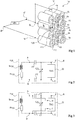
- the figure 1 is a perspective view schematically showing an example of an embodiment of a communication system between a master device M, or reader, and at least one slave device S in an electric battery 14.
- the battery 14 comprises twelve elementary cells c 1 to c 12 connected in series between terminals V + and V- for supplying a DC voltage.
- the slave device S comprises for example a temperature sensor or an electronic identification tag, and is connected to the terminals of an elementary cell of the battery (cell c 10 in this example) via the two contacts A and B.
- the master device M is connected to the main terminals V + and V- of the battery 14 via two contacts C and D.
- the master device M is adapted to apply an alternating signal on the main terminals V + and V- of the battery, that is to say to emit, on the power path of the battery , an alternating signal superimposed on the DC voltage of the battery.
- the slave device S connected in parallel with a portion of the power path of the battery, is adapted to communicate with the device M by demodulating and / or modulating the AC signal seen on its terminals A and B.
- the slave device S could be housed inside the housing, and the master device M could be located outside the housing, and connected to terminals V + and V-.
- the figure 2 is an electrical diagram illustrating in more detail one embodiment of the slave device S connected to the elementary cell c 10 of the electric battery 14 of the figure 1 .
- the elementary cell c 10 behaves as an inductance Lc 10 in series with a resistor Rc 10 .
- the values of the inductance Lc 10 and the resistance Rc 10 depend, among other factors, on the technology for producing the cell 10 ' of its structure, etc.
- the slave device S forms, with the own inductance Lc 10 and the resistor Rc 10 of the cell c 10 to which it is connected, a resonant assembly.
- the slave device S comprises a main circuit 21 (TAG), or processing circuit, comprising two terminals F and G for applying an alternating signal.
- TAG main circuit 21
- Two isolation (or decoupling) capacitors CI are provided respectively between terminal A and terminal F, and between terminal B and terminal G, to prevent the DC voltage of cell c 10 from being applied to terminals F and G of the circuit 21.
- the circuit 21 therefore sees at its terminals only the alternating signal propagated by the master device M on the power path of the battery.
- CI capacitors possible in particular to prevent the cell c 10 from draining into the circuit 21.
- the S device further comprises a tuning capacitor CA of the resonant frequency of the assembly formed by the device S, the inductance Lc 10 ' and resistor Rc 10 .
- the capacitor CA is connected between the terminals F and G.
- the capacitor CA is for example a capacitor with variable capacitance.
- the AC capacity is chosen according to the frequency of the alternating signal applied by the device M to the terminals V + and V- of the battery, so that the resonant assembly formed by the device and the cell S c 10 resonates at this frequency.
- the alternating signal seen by the circuit 21 on its terminals F and G is an amplified copy of the alternating signal propagated by the master device M on the power path of the battery.
- the resonant frequency of the resonant assembly is essentially a function of the AC capacitance and the Lc 10 inductance.
- the circuit 21 comprises for example a modulation circuit of the AC signal seen at its terminals F and G, allowing it to transmit data to the master device M via the power path of the battery.
- the data transmitted by the circuit 21 may be an identification number contained in a memory of the circuit 21, a temperature measurement made by a sensor of the circuit 21, or any other data.
- the circuit 21 may for example vary its own impedance, resulting in a variation of amplitude of the alternating signal propagated on the power path of the battery. Any other suitable modulation method may however be used (frequency modulation, phase modulation, etc.).
- the circuit 21 may further comprise a demodulation circuit of the alternating signal seen on its terminals F and G, so as to allow two-way communication between the master device M and the slave device S.
- the circuit 21 may comprise a power supply unit (not shown), comprising means for rectifying the AC signal seen terminals F and G and providing a DC voltage rectified across a capacitor. This allows the circuit 21 to draw its electrical power supply not directly in the cell c 10 ' but in the alternating signal emitted by the reader M (it being understood that the reader M can be powered either by the battery 14 or by a external source).
- sensors or other electronic devices adapted to communicate by radio waves with a remote reader, generally according to standardized protocols.
- sensors equipped with an antenna or comprising terminals for connection to an antenna and which already include modulation, demodulation or production circuits for a continuous supply voltage by rectifying an alternating signal. provided by the antenna.
- TAG circuit 21
- the existing device already includes an antenna this antenna is previously removed, otherwise the existing device can be used as is.
- the terminals F and G by which the existing device is connected to the capacitors CI and CA are the terminals normally intended to be connected to an antenna.
- the existing device can be used without further modification since, from the point of view of the sensor, it is irrelevant whether the alternating signal seen on the terminals F and G is propagated from or to the master device by the airs (via an antenna) or by the power path of the battery.
- RFID Radio Frequency Identification
- devices adapted to operate in accordance with a communication protocol described in ISO 15693, normally targeting wireless contactless communication over a carrier frequency at 13.56 MHz may be used.
- the frequency of the alternating signal emitted by the master device M is then set at 13.56 MHz, and the AC tuning capacity of the slave device S is chosen so that the resonance frequency of the resonant assembly comprising the slave device S c and the cell 10 is approximately 13.56 MHz.
- the master device M can be produced from an existing reader comprising an alternating signal generator intended to be connected to an antenna, and means for modulating and / or demodulating transmitted signals and / or or received by the antenna. If the existing player already has an antenna, this antenna is removed beforehand.
- the terminals V + and V- of the battery can be connected instead of the antenna via isolation capacitors or decoupling to prevent the DC voltage of the battery is applied to the reader.
- the described embodiments are of course not limited to the reuse of existing elements of non-contact radio communication systems.
- any working frequency other than 13.56 MHz may be used.
- the inventors have found that the frequencies between 30 kHz and 30 MHz are particularly suitable for the implementation of robust communications via the power path of the battery.
- the figure 3 is an electrical diagram illustrating an alternative embodiment of the slave device S of the figure 2 .
- the device of the figure 3 differs from the device of the figure 2 in that the circuit 21 is powered not by rectifying the alternating signal seen at its terminals F and G, but by a direct voltage taken directly across the cell to which the device S is connected.
- the circuit 21 has terminals H and I for applying a DC supply voltage.
- the terminals H and I are respectively connected to the terminals A and B of the device S, that is to say upstream of the isolation capacitors CI.
- the terminals H and I directly receive the DC voltage delivered by this cell.
- the figure 4 is an electrical diagram illustrating an exemplary embodiment of a communication system between a master device M and slave devices S i in an electric battery in which elementary cells c i are connected in series between terminals V + and V- of the battery (a slave device per cell, i ranging from 1 to 4 in this example).
- the slave devices S 1 to S 4 are for example devices of the type described in connection with the figure 2 , and are respectively connected in parallel cells c 1 to c 4 (on the figure 4 each cell c i is schematically represented by an inductance Lc i in series with a resistor Rc i ).
- each cell c i is schematically represented by an inductance Lc i in series with a resistor Rc i ).
- the resonance setting is done by the AC tuning capabilities. This setting depends in particular on the number of cells instrumented. If a slave device S i is connected in parallel with a chain of several elementary cells c i in series, it will be necessary to take into account, for the adjustment of the resonance, the proper inductance and the intrinsic resistance of this chain of cells. .
- the master device M is modeled by an alternating AC signal generator in series with a resistance rg (generator internal resistance).
- rg generator internal resistance
- the load seen by the generator at its output terminals J and K is equal to its internal impedance rg (typically 50 Ohms).
- an impedance transformer 41 may be provided between the output terminals J and K of the AC generator and terminals L and P respectively connected to terminals V + and V- of the battery.
- the terminal L is connected to the terminal V + via a tuning capacitor CA 'in series with an isolation capacitor CI', and the terminal O is connected to the terminal V- by the intermediate of a second capacitor CA 'in series with a second capacitor CI'.
- the impedance (charge) seen by the transformer 41 at its terminals L and P must be purely real.
- the tuning capacitors CA ' for example capacitors with variable capacitance, are provided to compensate for parasitic inductances related to the connection elements between the cells of the battery.
- the capacitors CI 'isolation or decoupling are provided to prevent the DC voltage of the battery is applied to the terminals L and P of the impedance transformer 41.
- a protection resistor Rp may be provided between a node N common to the first capacitor CA 'and to the first capacitor CI ', and a node O common to the second capacitor CA' and the second capacitor CI '.
- the resistor Rp makes it possible in particular to discharge the isolation capacitors CI 'in case of disconnection of the battery.
- the master device M may comprise means for modulating and / or demodulating the alternating signals transmitted and / or received via the battery power path, and processing means for coding and / or decoding the messages transmitted. and / or received.
- the figure 5 is an electrical diagram illustrating an exemplary embodiment of a communication system between a master device M and slave devices S i in an electric battery in which elementary cells c i are connected in parallel between the terminals V + and V- of the battery (one slave device per cell, i ranging from 1 to 3 in this example).
- the master device M and the slave devices S i are of the same type as in the example of FIG. figure 4 , but the slave devices S i of the system of the figure 5 are connected in parallel between terminals V + and V-, and not in series as in the system of the figure 4 .
- the resonance setting is done by the AC tuning capabilities.
- An advantage of the proposed communication mode is that it allows reliable communications between a master device and at least one slave device in an electric battery.
- this mode of communication is not very sensitive to disturbances of the environment.
- the resonators used, on the slave devices side, to communicate with the master device use the own inductance of the cells of the battery as a resonant element. This allows a saving of components (inductances).
- a battery can be divided into several modules each comprising a plurality of cells connected in series or in parallel between two nodes or contact terminals of the module, the modules being connected in series or in parallel between the terminals drums.
- modules being connected in series or in parallel between the terminals drums.
- those skilled in the art will be able to add modularity to the communication system described above.
- provision may be made, for each module or group of modules, of a master device of a first rank, a higher-ranking master device being provided for communicating with the lower-rank master devices (network arborescent).
- those skilled in the art will adapt any known network structure to the communication mode described above.
- those skilled in the art will be able to provide adapted communication protocols.
- those skilled in the art can plan to use several carrier frequencies in the same battery.
- figure 1 represents a slave device S located outside an elementary cell of the battery
- the described communication mode also allows to provide sensors inside the cells, for example a sensor of the electrolyte temperature.
- the proposed communication system is then particularly advantageous since it makes it possible to dispense with any specific connection (other than the power terminals of the cell) outside the cell.
Description
La présente invention concerne des communications entre un dispositif maître et un ou plusieurs dispositifs esclaves dans une batterie électrique.The present invention relates to communications between a master device and one or more slave devices in an electric battery.
Une batterie électrique est un groupement de plusieurs cellules élémentaires (piles, accumulateurs, etc.) reliées en série et/ou en parallèle entre deux noeuds ou bornes de fourniture d'une tension continue.An electric battery is a group of several elementary cells (batteries, accumulators, etc.) connected in series and / or in parallel between two nodes or terminals for supplying a DC voltage.
Les cellules de la batterie sont généralement logées dans un boîtier de protection ne laissant accessible que deux cosses respectivement connectées aux deux bornes de la batterie.The cells of the battery are generally housed in a protective housing leaving only two lugs respectively connected to the two terminals of the battery.
Dans certaines applications, par exemple dans le domaine des batteries pour véhicules électriques, on souhaite pouvoir interroger des capteurs ou autres dispositifs électroniques situés à l'intérieur du boîtier de protection, par exemple des capteurs de température placés sur des cellules de la batterie, des étiquettes électroniques d'identification, ou tout autre type de dispositif.In some applications, for example in the field of batteries for electric vehicles, it is desired to be able to interrogate sensors or other electronic devices located inside the protective case, for example temperature sensors placed on cells of the battery, electronic identification tags, or any other type of device.
Pour cela, on peut prévoir une communication filaire entre un lecteur (dispositif maître), situé à l'extérieur du boîtier de la batterie, et les capteurs ou autres objets à interroger (dispositifs esclaves), situés à l'intérieur du boîtier. Un inconvénient réside dans la nécessité de faire sortir des câbles à l'extérieur du boîtier, ce qui implique de prévoir des connecteurs et un risque d'arrachage. En outre, le nombre de câbles nécessaires à l'instrumentation d'une batterie peut être important, entraînant une augmentation non négligeable du prix de revient de la batterie. De plus, les câbles peuvent capter des perturbations électromagnétiques susceptibles d'altérer les signaux de données entre le dispositif maître et les dispositifs esclaves.For this, one can provide a wired communication between a reader (master device), located outside the battery housing, and sensors or other objects to be interrogated (slave devices), located inside the housing. A disadvantage lies in the need to remove cables outside the housing, which involves providing connectors and a risk of tearing. In addition, the number of cables needed for the instrumentation of a battery can be significant, resulting in a significant increase in the cost price of the battery. In addition, the cables can pick up electromagnetic disturbances that could to alter the data signals between the master device and the slave devices.
Pour éviter les inconvénients d'une communication filaire, on pourrait utiliser des communications par ondes radio (sans contact) entre le dispositif maître et les dispositifs esclaves. Toutefois, l'environnement, souvent fortement métallique, rend de telles communications difficiles et aléatoires.To avoid the drawbacks of wired communication, it would be possible to use radio wave (non-contact) communications between the master device and the slave devices. However, the environment, often highly metallic, makes such communications difficult and random.
Il serait souhaitable de pouvoir disposer d'un moyen fiable et peu coûteux pour communiquer avec des capteurs ou autres dispositifs situés à l'intérieur d'une batterie.It would be desirable to have a reliable and inexpensive means for communicating with sensors or other devices within a battery.
Les documents
La demande de brevet
Ainsi, un objet d'un mode de réalisation de la présente invention vise un système de communication entre un dispositif maître et au moins un dispositif esclave dans une batterie électrique, ce système palliant au moins en partie certains des inconvénients des systèmes connus.Thus, an object of an embodiment of the present invention is a communication system between a master device and at least one slave device in an electric battery, this system at least partially overcoming some of the disadvantages of known systems.
Un autre objet d'un mode de réalisation de la présente invention est de prévoir un système de communication plus fiable que les systèmes connus.Another object of an embodiment of the present invention is to provide a more reliable communication system than known systems.
Un autre objet d'un mode de réalisation de la présente invention est de prévoir un système de communication moins onéreux que les systèmes connus.Another object of an embodiment of the present invention is to provide a less expensive communication system than the known systems.
Un autre objet d'un mode de réalisation de la présente invention est de prévoir un procédé de communication entre un dispositif maître et un ou plusieurs dispositifs esclaves dans une batterie électrique.Another object of an embodiment of the present invention is to provide a method of communication between a master device and one or more slave devices in an electric battery.
Ainsi, un mode de réalisation de la présente invention prévoit un système comprenant : une batterie dans laquelle une pluralité de cellules élémentaires sont reliées entre deux premiers noeuds ; un premier dispositif adapté à appliquer un signal alternatif aux premiers noeuds ; au moins un deuxième dispositif connecté à deux deuxièmes noeuds de la pluralité de cellules ; et au moins un ensemble résonant dont un élément inductif comporte l'inductance propre de la batterie entre les deuxièmes noeuds.Thus, an embodiment of the present invention provides a system comprising: a battery in which a plurality of elementary cells are connected between two first nodes; a first device adapted to apply a alternative signal to the first nodes; at least one second device connected to two second nodes of the plurality of cells; and at least one resonant assembly of which an inductive element comprises the own inductance of the battery between the second nodes.
Selon la présente invention, l'ensemble résonant comporte au moins un élément capacitif dudit au moins un deuxième dispositif.According to the present invention, the resonant assembly comprises at least one capacitive element of said at least one second device.
Selon la présente invention, ledit au moins un deuxième dispositif est adapté à communiquer avec le premier dispositif par modulation dudit signal alternatif vu par les deuxièmes noeuds.According to the present invention, said at least one second device is adapted to communicate with the first device by modulation of said alternative signal seen by the second nodes.
Selon la présente invention, la fréquence de résonance dudit ensemble résonant est approximativement égale à la fréquence dudit signal alternatif.According to the present invention, the resonance frequency of said resonant assembly is approximately equal to the frequency of said alternating signal.
Selon un mode de réalisation de la présente invention, la fréquence de résonance dudit ensemble résonant est comprise entre 30 kHz et 30 MHz.According to one embodiment of the present invention, the resonance frequency of said resonant assembly is between 30 kHz and 30 MHz.
Selon un mode de réalisation de la présente invention, les deuxièmes noeuds sont deux bornes de puissance d'une même cellule élémentaire.According to one embodiment of the present invention, the second nodes are two power terminals of the same elementary cell.
Selon un mode de réalisation de la présente invention, les cellules de la batterie sont connectées en série entre lesdits premiers noeuds.According to an embodiment of the present invention, the cells of the battery are connected in series between said first nodes.
Selon un mode de réalisation de la présente invention, les cellules de la batterie sont connectées en parallèle entre les premiers noeuds.According to one embodiment of the present invention, the cells of the battery are connected in parallel between the first nodes.
Selon un mode de réalisation de la présente invention, ledit au moins un deuxième dispositif comprend un circuit de traitement comportant deux troisièmes noeuds, ledit au moins un deuxième dispositif comportant des condensateurs d'isolement entre les troisièmes noeuds et les deuxièmes noeuds.According to an embodiment of the present invention, said at least one second device comprises a processing circuit comprising two third nodes, said at least one second device comprising isolation capacitors between the third nodes and the second nodes.
Selon un mode de réalisation de la présente invention, le premier dispositif comprend un générateur alternatif et un transformateur d'impédance entre ledit générateur et lesdits premiers noeuds.According to an embodiment of the present invention, the first device comprises an alternating generator and an impedance transformer between said generator and said first nodes.
Selon un mode de réalisation de la présente invention, le premier dispositif comprend des condensateurs d'accord en fréquence et des condensateurs d'isolement entre ledit transformateur et lesdits premiers noeuds.According to an embodiment of the present invention, the first device comprises frequency tuning capacitors and isolation capacitors between said transformer and said first nodes.
La présente invention prévoit aussi une batterie électrique comportant : une pluralité de cellules élémentaires reliées entre deux premiers noeuds ; au moins un dispositif connecté à deux deuxième noeuds de ladite pluralité de cellules ; et au moins un ensemble résonant dont un élément inductif comporte l'inductance propre de la batterie entre lesdits deuxièmes noeuds.The present invention also provides an electric battery comprising: a plurality of elementary cells connected between two first nodes; at least one device connected to two second nodes of said plurality of cells; and at least one resonant assembly of which an inductive element comprises the own inductance of the battery between said second nodes.
Selon la présente invention, ledit au moins un dispositif est adapté à moduler un signal alternatif reçu par les deuxièmes noeuds.According to the present invention, said at least one device is adapted to modulate an alternating signal received by the second nodes.
Selon un mode de réalisation de la présente invention, l'ensemble résonant comporte au moins un élément capacitif dudit au moins un dispositif.According to one embodiment of the present invention, the resonant assembly comprises at least one capacitive element of said at least one device.
Selon un mode de réalisation de la présente invention, ledit au moins un dispositif est situé à l'intérieur d'une cellule élémentaire de la batterie.According to an embodiment of the present invention, said at least one device is located inside an elementary cell of the battery.
Selon un mode de réalisation de la présente invention, ledit au moins un dispositif comprend un capteur apte à mesurer la température de l'électrolyte de la cellule.According to one embodiment of the present invention, said at least one device comprises a sensor capable of measuring the temperature of the electrolyte of the cell.
Selon la présente invention, une pluralité de cellules élémentaires sont reliées entre deux premiers noeuds, entre un premier dispositif relié auxdits premiers noeuds et au moins un deuxième dispositif connecté à deux deuxièmes noeuds de ladite pluralité de cellules, ce procédé comportant les étapes suivantes :
- côté premier dispositif, appliquer un signal alternatif auxdits premiers noeuds ; et
- côté deuxième dispositif, recevoir le signal alternatif par l'intermédiaire d'au moins un ensemble résonant dont un élément inductif comporte l'inductance propre de la batterie entre les deuxièmes noeuds, et moduler ledit signal.
- on the first device side, applying an alternating signal to said first nodes; and
- second side device, receive the alternating signal through at least one resonant assembly of which an inductive element comprises the own inductance of the battery between the second nodes, and modulate said signal.
Ces objets, caractéristiques et avantages, ainsi que d'autres seront exposés en détail dans la description suivante de modes de réalisation particuliers faite à titre non limitatif en relation avec les figures jointes parmi lesquelles :
- la
figure 1 est une vue en perspective représentant schématiquement un mode de réalisation d'un système de communication entre un dispositif maître et un dispositif esclave inclus dans une batterie électrique ; - la
figure 2 est un schéma électrique illustrant un mode de réalisation d'un dispositif esclave associé à une cellule élémentaire d'une batterie électrique ; - la
figure 3 est un schéma électrique illustrant une variante de réalisation du dispositif esclave de lafigure 2 ; - la
figure 4 est un schéma électrique illustrant un mode de réalisation d'un système de communication entre un dispositif maître, et des dispositifs esclaves inclus dans une batterie électrique dans laquelle des cellules élémentaires sont reliées en série ; et - la
figure 5 est un schéma électrique illustrant un mode de réalisation d'un système de communication entre un dispositif maître, et des dispositifs esclaves dans une batterie électrique dans laquelle des cellules élémentaires sont reliées en parallèle.
- the
figure 1 is a perspective view schematically showing an embodiment of a communication system between a master device and a slave device included in an electric battery; - the
figure 2 is an electrical diagram illustrating an embodiment of a slave device associated with an elementary cell of an electric battery; - the
figure 3 is an electrical diagram illustrating an alternative embodiment of the slave device of thefigure 2 ; - the
figure 4 is an electrical diagram illustrating an embodiment of a communication system between a master device, and slave devices included in an electric battery in which elementary cells are connected in series; and - the
figure 5 is an electrical diagram illustrating an embodiment of a communication system between a master device, and slave devices in an electric battery in which elementary cells are connected in parallel.
De mêmes éléments ont été désignés par de mêmes références aux différentes figures. Par souci de clarté, seuls les éléments utiles à la compréhension de l'invention ont été représentés et seront décrits. En particulier, les fonctions des dispositifs esclaves n'ont pas été détaillées, les modes de réalisation étant compatibles avec les dispositifs électroniques usuels susceptibles d'être placés à l'intérieur d'une batterie électrique.The same elements have been designated with the same references in the various figures. For the sake of clarity, only the elements useful for understanding the invention have been shown and will be described. In particular, the functions of the slave devices have not been detailed, the embodiments being compatible with the usual electronic devices that can be placed inside an electric battery.
La
Selon un aspect du mode de réalisation décrit, le dispositif maître M est adapté à appliquer un signal alternatif sur les bornes principales V+ et V- de la batterie, c'est-à-dire à émettre, sur le chemin de puissance de la batterie, un signal alternatif se superposant à la tension continue de la batterie. Le dispositif esclave S, connecté en parallèle d'une portion du chemin de puissance de la batterie, est adapté à communiquer avec le dispositif M en démodulant et/ou en modulant le signal alternatif vu sur ses bornes A et B.According to one aspect of the embodiment described, the master device M is adapted to apply an alternating signal on the main terminals V + and V- of the battery, that is to say to emit, on the power path of the battery , an alternating signal superimposed on the DC voltage of the battery. The slave device S, connected in parallel with a portion of the power path of the battery, is adapted to communicate with the device M by demodulating and / or modulating the AC signal seen on its terminals A and B.
Par souci de clarté, aucun boîtier de protection de la batterie 14 n'a été représenté sur la
La
Du point de vue du signal alternatif émis par le dispositif maître M (non visible sur la
Selon un aspect du mode de réalisation décrit, le dispositif esclave S forme, avec l'inductance propre Lc10 et la résistance propre Rc10 de la cellule c10 aux bornes de laquelle il est connecté, un ensemble résonant.According to one aspect of the embodiment described, the slave device S forms, with the own inductance Lc 10 and the resistor Rc 10 of the cell c 10 to which it is connected, a resonant assembly.
Le dispositif esclave S comprend un circuit principal 21 (TAG), ou circuit de traitement, comportant deux bornes F et G d'application d'un signal alternatif. Deux condensateurs d'isolement (ou de découplage) CI sont prévus respectivement entre la borne A et la borne F, et entre la borne B et la borne G, pour empêcher que la tension continue de la cellule c10 ne soit appliquée aux bornes F et G du circuit 21. Le circuit 21 ne voit donc à ses bornes que le signal alternatif propagé par le dispositif maître M sur le chemin de puissance de la batterie. Les condensateurs CI permettent en particulier d'éviter que la cellule c10 ne se décharge dans le circuit 21. Le dispositif S comporte en outre un condensateur CA d'accord de la fréquence de résonance de l'ensemble formé par le dispositif S, l'inductance Lc10' et la résistance Rc10. Dans cet exemple, le condensateur CA est connecté entre les bornes F et G. Le condensateur CA est par exemple un condensateur à capacité variable. La capacité CA est choisie en fonction de la fréquence du signal alternatif appliqué par le dispositif M aux bornes V+ et V- de la batterie, de façon que l'ensemble résonant formé par le dispositif S et la cellule c10 résonne à cette fréquence. Ainsi, le signal alternatif vu par le circuit 21 sur ses bornes F et G est une copie amplifiée du signal alternatif propagé par le dispositif maître M sur le chemin de puissance de la batterie. En pratique, la fréquence de résonance de l'ensemble résonant est essentiellement fonction de la capacité CA et de l'inductance Lc10.The slave device S comprises a main circuit 21 (TAG), or processing circuit, comprising two terminals F and G for applying an alternating signal. Two isolation (or decoupling) capacitors CI are provided respectively between terminal A and terminal F, and between terminal B and terminal G, to prevent the DC voltage of cell c 10 from being applied to terminals F and G of the
Le circuit 21 comprend par exemple un circuit de modulation du signal alternatif vu sur ses bornes F et G, lui permettant d'émettre des données à destination du dispositif maître M, via le chemin de puissance de la batterie. Les données émises par le circuit 21 peuvent être un numéro d'identification contenu dans une mémoire du circuit 21, une mesure de température réalisée par un capteur du circuit 21, ou toutes autres données. Pour moduler le signal alternatif propagé sur le chemin de puissance de la batterie, le circuit 21 peut par exemple faire varier son impédance propre, entraînant une variation d'amplitude du signal alternatif propagé sur le chemin de puissance de la batterie. Tout autre procédé de modulation adapté pourra cependant être utilisé (modulation de fréquence, modulation de phase, etc.). Le circuit 21 peut en outre comprendre un circuit de démodulation du signal alternatif vu sur ses bornes F et G, de façon à permettre une communication bidirectionnelle entre le dispositif maître M et le dispositif esclave S.The
Pour son alimentation en énergie électrique, le circuit 21 peut comprendre un bloc d'alimentation (non représenté), comportant des moyens de redressement du signal alternatif vu par les bornes F et G et de fourniture d'une tension continue redressée aux bornes d'un condensateur. Ceci permet que le circuit 21 puise son énergie électrique d'alimentation non pas directement dans la cellule c10' mais dans le signal alternatif émis par le lecteur M (étant entendu que le lecteur M peut être alimenté soit par la batterie 14 soit par une source externe).For its power supply, the
Dans un mode de réalisation préféré, on tire profit du fait qu'il existe déjà de nombreux capteurs ou autres dispositifs électroniques (par exemple d'identification) adaptés à communiquer par ondes radio avec un lecteur distant, généralement selon des protocoles normalisés. Il existe par exemple des capteurs équipés d'une antenne ou comprenant des bornes de connexion à une antenne, et comprenant déjà des circuits de modulation, de démodulation, ou de production d'une tension d'alimentation continue par redressement d'un signal alternatif fourni par l'antenne. On propose ici d'utiliser un capteur ou autre dispositif existant de ce type pour réaliser le circuit 21 (TAG). Si le dispositif existant comprend déjà une antenne, cette antenne est préalablement retirée, sinon, le dispositif existant peut être utilisé tel quel. Les bornes F et G par lesquelles le dispositif existant est connecté aux condensateurs CI et CA sont les bornes normalement destinées à être connectées à une antenne. Le dispositif existant peut être utilisé sans autre modification car, du point de vue du capteur, il est indifférent que le signal alternatif vu sur les bornes F et G soit propagé depuis ou vers le dispositif maître par les airs (par l'intermédiaire d'une antenne) ou par le chemin de puissance de la batterie.In a preferred embodiment, it takes advantage of the fact that there are already many sensors or other electronic devices (eg identification) adapted to communicate by radio waves with a remote reader, generally according to standardized protocols. There are, for example, sensors equipped with an antenna or comprising terminals for connection to an antenna, and which already include modulation, demodulation or production circuits for a continuous supply voltage by rectifying an alternating signal. provided by the antenna. It is proposed here to use a sensor or other existing device of this type to produce the circuit 21 (TAG). If the existing device already includes an antenna, this antenna is previously removed, otherwise the existing device can be used as is. The terminals F and G by which the existing device is connected to the capacitors CI and CA are the terminals normally intended to be connected to an antenna. The existing device can be used without further modification since, from the point of view of the sensor, it is irrelevant whether the alternating signal seen on the terminals F and G is propagated from or to the master device by the airs (via an antenna) or by the power path of the battery.
A titre d'exemple, on peut utiliser, pour réaliser les dispositifs esclaves, des capteurs ou autres dispositifs électroniques normalement destinés à être utilisés dans des systèmes de communication sans contact de type RFID (de l'anglais "Radio Frequency Identification" - identification par fréquence radio). Par exemple, on peut utiliser des dispositifs adaptés à fonctionner selon un protocole de communication décrit dans la norme ISO 15693, visant normalement la communication sans contact par ondes radio sur une fréquence porteuse à 13,56 MHz. La fréquence du signal alternatif émis par le dispositif maître M est alors réglée à 13,56 MHz, et la capacité d'accord CA du dispositif esclave S est choisie de façon que la fréquence de résonance de l'ensemble résonant comprenant le dispositif esclave S et la cellule c10 soit d'approximativement 13,56 MHz.By way of example, sensors or other electronic devices normally intended to be used in contactless communication systems of the RFID (Radio Frequency Identification) type - identification by radio frequency). For example, devices adapted to operate in accordance with a communication protocol described in ISO 15693, normally targeting wireless contactless communication over a carrier frequency at 13.56 MHz, may be used. The frequency of the alternating signal emitted by the master device M is then set at 13.56 MHz, and the AC tuning capacity of the slave device S is chosen so that the resonance frequency of the resonant assembly comprising the slave device S c and the cell 10 is approximately 13.56 MHz.
De même que le dispositif esclave S, le dispositif maître M peut être réalisé à partir d'un lecteur existant comportant un générateur de signal alternatif destiné à être relié à une antenne, et des moyens de modulation et/ou démodulation de signaux émis et/ou reçus par l'antenne. Si le lecteur existant comporte déjà une antenne, cette antenne est préalablement retirée. Les bornes V+ et V- de la batterie peuvent être connectées à la place de l'antenne par l'intermédiaire de condensateurs d'isolement ou de découplage permettant d'éviter que la tension continue de la batterie ne soit appliquée au lecteur.As well as the slave device S, the master device M can be produced from an existing reader comprising an alternating signal generator intended to be connected to an antenna, and means for modulating and / or demodulating transmitted signals and / or or received by the antenna. If the existing player already has an antenna, this antenna is removed beforehand. The terminals V + and V- of the battery can be connected instead of the antenna via isolation capacitors or decoupling to prevent the DC voltage of the battery is applied to the reader.
Les modes de réalisation décrits ne se limitent bien entendu pas à la réutilisation d'éléments existants de systèmes de communication sans contact par ondes radio. On pourra par exemple aussi prévoir un protocole de communication spécifique, et réaliser des dispositifs maître et esclave(s) spécifiquement dédiés à la mise en oeuvre de ce protocole. En particulier, toute fréquence de travail autre que 13,56 MHz pourra être utilisée. Les inventeurs ont constaté que les fréquences comprises entre 30 kHz et 30 MHz sont particulièrement adaptées à la mise en oeuvre de communications robustes via le chemin de puissance de la batterie.The described embodiments are of course not limited to the reuse of existing elements of non-contact radio communication systems. For example, it is also possible to provide a specific communication protocol, and to make master and slave devices specifically dedicated to the implementation of this protocol. In particular, any working frequency other than 13.56 MHz may be used. The inventors have found that the frequencies between 30 kHz and 30 MHz are particularly suitable for the implementation of robust communications via the power path of the battery.
La
La
Le réglage de la résonance se fait par les capacités d'accord CA. Ce réglage dépend notamment du nombre de cellules instrumentées. Si un dispositif esclave Si est connecté en parallèle d'une chaîne de plusieurs cellules élémentaires ci en série, il faudra tenir compte, pour le réglage de la résonance, de l'inductance propre et de la résistance propre de cette chaîne de cellules.The resonance setting is done by the AC tuning capabilities. This setting depends in particular on the number of cells instrumented. If a slave device S i is connected in parallel with a chain of several elementary cells c i in series, it will be necessary to take into account, for the adjustment of the resonance, the proper inductance and the intrinsic resistance of this chain of cells. .
Dans l'exemple de la
Idéalement, l'impédance (charge) vue par le transformateur 41 à ses bornes L et P doit être purement réelle. Les condensateurs d'accord CA', par exemple des condensateurs à capacité variable, sont prévus pour compenser les inductances parasites liées aux éléments de connexion entre les cellules de la batterie.Ideally, the impedance (charge) seen by the
Les condensateurs CI' d'isolement ou de découplage sont prévus pour empêcher que la tension continue de la batterie ne soit appliquée aux bornes L et P du transformateur d'impédance 41.The capacitors CI 'isolation or decoupling are provided to prevent the DC voltage of the battery is applied to the terminals L and P of the
Une résistance de protection Rp peut être prévue entre un noeud N commun au premier condensateur CA' et au premier condensateur CI', et un noeud O commun au second condensateur CA' et au second condensateur CI'. La résistance Rp permet en particulier de décharger les condensateurs d'isolement CI' en cas de déconnexion de la batterie.A protection resistor Rp may be provided between a node N common to the first capacitor CA 'and to the first capacitor CI ', and a node O common to the second capacitor CA' and the second capacitor CI '. The resistor Rp makes it possible in particular to discharge the isolation capacitors CI 'in case of disconnection of the battery.
Outre les éléments représentés sur la
La
Un avantage du mode de communication proposé est qu'il permet des communications fiables entre un dispositif maître et au moins un dispositif esclave dans une batterie électrique.An advantage of the proposed communication mode is that it allows reliable communications between a master device and at least one slave device in an electric battery.
En particulier, ce mode de communication est peu sensible aux perturbations de l'environnement.In particular, this mode of communication is not very sensitive to disturbances of the environment.
De plus, il n'est pas nécessaire de prévoir des câbles allant de l'intérieur vers l'extérieur de la batterie.In addition, it is not necessary to provide cables from the inside to the outside of the battery.
En outre, les résonateurs utilisés, côté dispositifs esclaves, pour communiquer avec le dispositif maître, utilisent l'inductance propre des cellules de la batterie comme élément résonant. Ceci permet une économie de composants (inductances).In addition, the resonators used, on the slave devices side, to communicate with the master device, use the own inductance of the cells of the battery as a resonant element. This allows a saving of components (inductances).
Des modes de réalisation particuliers ont été décrits. Diverses variantes et modifications apparaîtront à l'homme de l'art.Particular embodiments have been described. Various variations and modifications will be apparent to those skilled in the art.
En particulier, il est connu qu'une batterie peut être divisée en plusieurs modules comprenant chacun une pluralité de cellules reliées en série ou en parallèle entre deux noeuds ou bornes de contact du module, les modules étant reliés en série ou en parallèle entre les bornes de la batterie. Bien que cela n'ait pas été mentionné ci-dessus, l'homme de l'art saura ajouter de la modularité au système de communication décrit ci-dessus. Par exemple, dans une batterie à plusieurs modules, on pourra prévoir, pour chaque module ou groupe de modules, un dispositif maître d'un premier rang, un dispositif maître de rang supérieur étant prévu pour communiquer avec les dispositifs maîtres de rang inférieur (réseau arborescent). De façon générale, l'homme de l'art saura adapter toute structure de réseau connue au mode de communication décrit ci-dessus. Le cas échéant, l'homme de l'art saura prévoir des protocoles de communication adaptés. En particulier, l'homme de l'art pourra prévoir d'utiliser plusieurs fréquences porteuses dans une même batterie.In particular, it is known that a battery can be divided into several modules each comprising a plurality of cells connected in series or in parallel between two nodes or contact terminals of the module, the modules being connected in series or in parallel between the terminals drums. Although not mentioned above, those skilled in the art will be able to add modularity to the communication system described above. For example, in a multi-module battery, provision may be made, for each module or group of modules, of a master device of a first rank, a higher-ranking master device being provided for communicating with the lower-rank master devices (network arborescent). In general, those skilled in the art will adapt any known network structure to the communication mode described above. Where appropriate, those skilled in the art will be able to provide adapted communication protocols. In particular, those skilled in the art can plan to use several carrier frequencies in the same battery.
De plus, bien que la
Claims (10)
- System comprising:a battery (14) in which a plurality of elementary cells (ci) are connected between two first nodes (V+, V-);a first device (M) suitable for applying an alternating signal to said first nodes (V+, V-);at least one second device (S, Si) connected to two second nodes (A, B) of the plurality of cells; andat least one resonant assembly, of which an inductive element comprises the inductor (Lci) belonging to the battery between said second nodes (A, B),the system being characterized in that said second device is suitable for communicating with the first device by modulation, substantially at the resonance frequency of said resonant assembly, of the alternating signal seen by the second nodes (A, B).
- System according to Claim 1, wherein said at least one resonant assembly has at least one capacitive element (CA) of said at least one second device (S, Si).
- System according to any one of Claims 1 to 3, wherein the resonance frequency of said resonant assembly is between 30 kHz and 30 MHz.
- System according to any one of Claims 1 to 4, wherein said second nodes (A, B) are two power terminals of the same elementary cell (ci).
- System according to any one of Claims 1 to 5, wherein said at least one second device (S, Si) comprises a processing circuit (21, TAG) comprising two third nodes (F, G), said at least one second device comprising isolation capacitors (CI) between said third nodes (F, G) and said second nodes (A, B).
- System according to any one of Claims 1 to 5, wherein the first device (M) comprises an alternating generator (AC) and an impedance transformer (41) between said generator (AC) and said first nodes (V+, V-) .
- System according to Claim 6, wherein the first device comprises frequency tuning capacitors (CA) and isolation capacitors (CI) between said transformer (41) and said first nodes (V+, V-).
- System according to any one of the preceding claims, wherein the second device (S, Si) is arranged within an elementary cell (ci) of the battery.
- System according to the preceding claim, wherein the second device (S, Si) comprises a sensor able to measure the temperature of the electrolyte of the cell (ci) in which it is arranged.
- Method for communicating, in a battery (14) in which a plurality of elementary cells (ci) are connected between two first nodes (V+, V-), between a first device (M) connected to said first nodes (V+, V-) and at least one second device (S, Si) connected to two second nodes (A, B) of said plurality of cells, this method being characterized in that it comprises the following steps:on the side of the first device (M), applying an alternating signal to said first node (V+, V-); andon the side of the second device (S, Si), receiving said alternating signal via at least one resonant assembly, of which an inductive element comprises the inductor (Lci) belonging to the battery between said second nodes (A, B), and modulating said signal.
Applications Claiming Priority (2)
| Application Number | Priority Date | Filing Date | Title |
|---|---|---|---|
| FR1250871A FR2986392B1 (en) | 2012-01-31 | 2012-01-31 | COMMUNICATION SYSTEM IN AN ELECTRIC BATTERY |
| PCT/EP2013/051368 WO2013113617A1 (en) | 2012-01-31 | 2013-01-24 | Communication system in an electric battery |
Publications (2)
| Publication Number | Publication Date |
|---|---|
| EP2810334A1 EP2810334A1 (en) | 2014-12-10 |
| EP2810334B1 true EP2810334B1 (en) | 2018-10-03 |
Family
ID=47603751
Family Applications (1)
| Application Number | Title | Priority Date | Filing Date |
|---|---|---|---|
| EP13701097.1A Not-in-force EP2810334B1 (en) | 2012-01-31 | 2013-01-24 | Communication system in an electrical battery |
Country Status (4)
| Country | Link |
|---|---|
| US (1) | US9620825B2 (en) |
| EP (1) | EP2810334B1 (en) |
| FR (1) | FR2986392B1 (en) |
| WO (1) | WO2013113617A1 (en) |
Families Citing this family (6)
| Publication number | Priority date | Publication date | Assignee | Title |
|---|---|---|---|---|
| CN107636700B (en) * | 2014-12-10 | 2021-03-26 | 睿能创意公司 | Asset tracking system and method using temporary mesh network of mobile devices |
| DE102016210108A1 (en) * | 2016-06-08 | 2017-12-14 | Thyssenkrupp Ag | Charge balance arrangement and method for charge equalization |
| DE102016225691A1 (en) * | 2016-12-20 | 2018-06-21 | Bayerische Motoren Werke Aktiengesellschaft | High-voltage battery for a motor vehicle, in particular for a motor vehicle |
| US11398749B2 (en) * | 2017-05-22 | 2022-07-26 | Solaredge Technologies Ltd. | Method and apparatus to enable communication and control in a power system |
| GB2571931B (en) * | 2018-03-11 | 2020-07-22 | Puchianu Silviu | Comms come free battery |
| CN111817753A (en) * | 2020-07-03 | 2020-10-23 | 青岛鼎信通讯股份有限公司 | Zero-insertion-loss medium-voltage coupling device |
Family Cites Families (6)
| Publication number | Priority date | Publication date | Assignee | Title |
|---|---|---|---|---|
| US7059769B1 (en) * | 1997-06-27 | 2006-06-13 | Patrick Henry Potega | Apparatus for enabling multiple modes of operation among a plurality of devices |
| US6140800A (en) * | 1999-05-27 | 2000-10-31 | Peterson; William Anders | Autonomous battery equalization circuit |
| JP4707343B2 (en) * | 2003-07-31 | 2011-06-22 | パナソニック電工株式会社 | Lighting equipment |
| JP5355979B2 (en) * | 2008-09-26 | 2013-11-27 | 株式会社東芝 | Battery information acquisition device |
| DE102009040663A1 (en) * | 2009-09-09 | 2011-03-10 | Hoppecke Advanced Battery Technology Gmbh | Device for monitoring an energy store |
| JP5313941B2 (en) * | 2010-02-19 | 2013-10-09 | 株式会社日本自動車部品総合研究所 | Power line communication system |
-
2012
- 2012-01-31 FR FR1250871A patent/FR2986392B1/en not_active Expired - Fee Related
-
2013
- 2013-01-24 US US14/374,344 patent/US9620825B2/en active Active
- 2013-01-24 WO PCT/EP2013/051368 patent/WO2013113617A1/en active Application Filing
- 2013-01-24 EP EP13701097.1A patent/EP2810334B1/en not_active Not-in-force
Non-Patent Citations (1)
| Title |
|---|
| None * |
Also Published As
| Publication number | Publication date |
|---|---|
| EP2810334A1 (en) | 2014-12-10 |
| FR2986392B1 (en) | 2016-05-06 |
| US9620825B2 (en) | 2017-04-11 |
| US20150318583A1 (en) | 2015-11-05 |
| WO2013113617A1 (en) | 2013-08-08 |
| FR2986392A1 (en) | 2013-08-02 |
Similar Documents
| Publication | Publication Date | Title |
|---|---|---|
| EP2810334B1 (en) | Communication system in an electrical battery | |
| EP2515446B1 (en) | Receiver with wireless inductive supply | |
| CA2805082C (en) | Antenna for a moist environment | |
| CA2746241A1 (en) | Rfid antenna circuit | |
| EP2114019B1 (en) | Recharge of an active transponder | |
| FR2953314A1 (en) | SELF-PARAMETRATING RFID ANTENNA EXTENSION | |
| FR2943444A1 (en) | METHOD FOR ESTABLISHING A DATA LINK BETWEEN A FIRST PROCESSOR AND A SECURE PROCESSOR, IN PARTICULAR IN AN NFC CHIPSET | |
| WO2009059997A1 (en) | Wideband inductive antenna for contactless communication systems | |
| EP1164535B1 (en) | Device for generating an electromagnetic field for transponders | |
| EP3447930B1 (en) | Frequency adjustment of an nfc circuit | |
| EP2509227B1 (en) | Method for automatic impedance matching of a radio-frequency circuit and modular transmission or reception channel | |
| WO2015155041A1 (en) | Communication system in an electrical facility including batteries | |
| FR2982686A1 (en) | PROTECTION OF A RADIO FREQUENCY EMISSION-RECEPTION TERMINAL AGAINST ELECTROMAGNETIC DISTURBANCES | |
| FR2960083A1 (en) | DEVICE ON SEMICONDUCTOR SUBSTRATE FOR RFID INSTALLATION AS WELL AS MANUFACTURING METHOD | |
| FR2992123A1 (en) | ENERGY MANAGEMENT IN AN ELECTROMAGNETIC TRANSPONDER | |
| EP3054402B1 (en) | Microelectronic chip with multiple pads | |
| EP1309938B1 (en) | Antenna generating an electromagnetic field for transponder | |
| FR3085551A1 (en) | PROTECTION OF A PASSIVE TRANSPONDER SUBJECT TO A MAGNETIC FIELD GENERATED FOR EXAMPLE BY A NON-CONTACT CHARGER | |
| FR2988241A1 (en) | WIRELESS COMMUNICATION SYSTEM WITH MULTIPLE MULTIPLEX RECEIVERS. | |
| EP2304652B1 (en) | Electronic rfid tag |
Legal Events
| Date | Code | Title | Description |
|---|---|---|---|
| PUAI | Public reference made under article 153(3) epc to a published international application that has entered the european phase |
Free format text: ORIGINAL CODE: 0009012 |
|
| 17P | Request for examination filed |
Effective date: 20140718 |
|
| AK | Designated contracting states |
Kind code of ref document: A1 Designated state(s): AL AT BE BG CH CY CZ DE DK EE ES FI FR GB GR HR HU IE IS IT LI LT LU LV MC MK MT NL NO PL PT RO RS SE SI SK SM TR |
|
| AX | Request for extension of the european patent |
Extension state: BA ME |
|
| DAX | Request for extension of the european patent (deleted) | ||
| GRAP | Despatch of communication of intention to grant a patent |
Free format text: ORIGINAL CODE: EPIDOSNIGR1 |
|
| STAA | Information on the status of an ep patent application or granted ep patent |
Free format text: STATUS: GRANT OF PATENT IS INTENDED |
|
| INTG | Intention to grant announced |
Effective date: 20180502 |
|
| GRAS | Grant fee paid |
Free format text: ORIGINAL CODE: EPIDOSNIGR3 |
|
| GRAA | (expected) grant |
Free format text: ORIGINAL CODE: 0009210 |
|
| STAA | Information on the status of an ep patent application or granted ep patent |
Free format text: STATUS: THE PATENT HAS BEEN GRANTED |
|
| AK | Designated contracting states |
Kind code of ref document: B1 Designated state(s): AL AT BE BG CH CY CZ DE DK EE ES FI FR GB GR HR HU IE IS IT LI LT LU LV MC MK MT NL NO PL PT RO RS SE SI SK SM TR |
|
| REG | Reference to a national code |
Ref country code: GB Ref legal event code: FG4D Free format text: NOT ENGLISH |
|
| REG | Reference to a national code |
Ref country code: CH Ref legal event code: EP Ref country code: AT Ref legal event code: REF Ref document number: 1049625 Country of ref document: AT Kind code of ref document: T Effective date: 20181015 |
|
| REG | Reference to a national code |
Ref country code: IE Ref legal event code: FG4D Free format text: LANGUAGE OF EP DOCUMENT: FRENCH Ref country code: DE Ref legal event code: R096 Ref document number: 602013044423 Country of ref document: DE |
|
| REG | Reference to a national code |
Ref country code: NL Ref legal event code: MP Effective date: 20181003 |
|
| REG | Reference to a national code |
Ref country code: LT Ref legal event code: MG4D |
|
| REG | Reference to a national code |
Ref country code: AT Ref legal event code: MK05 Ref document number: 1049625 Country of ref document: AT Kind code of ref document: T Effective date: 20181003 |
|
| PG25 | Lapsed in a contracting state [announced via postgrant information from national office to epo] |
Ref country code: NL Free format text: LAPSE BECAUSE OF FAILURE TO SUBMIT A TRANSLATION OF THE DESCRIPTION OR TO PAY THE FEE WITHIN THE PRESCRIBED TIME-LIMIT Effective date: 20181003 |
|
| PG25 | Lapsed in a contracting state [announced via postgrant information from national office to epo] |
Ref country code: ES Free format text: LAPSE BECAUSE OF FAILURE TO SUBMIT A TRANSLATION OF THE DESCRIPTION OR TO PAY THE FEE WITHIN THE PRESCRIBED TIME-LIMIT Effective date: 20181003 Ref country code: AT Free format text: LAPSE BECAUSE OF FAILURE TO SUBMIT A TRANSLATION OF THE DESCRIPTION OR TO PAY THE FEE WITHIN THE PRESCRIBED TIME-LIMIT Effective date: 20181003 Ref country code: IS Free format text: LAPSE BECAUSE OF FAILURE TO SUBMIT A TRANSLATION OF THE DESCRIPTION OR TO PAY THE FEE WITHIN THE PRESCRIBED TIME-LIMIT Effective date: 20190203 Ref country code: CZ Free format text: LAPSE BECAUSE OF FAILURE TO SUBMIT A TRANSLATION OF THE DESCRIPTION OR TO PAY THE FEE WITHIN THE PRESCRIBED TIME-LIMIT Effective date: 20181003 Ref country code: NO Free format text: LAPSE BECAUSE OF FAILURE TO SUBMIT A TRANSLATION OF THE DESCRIPTION OR TO PAY THE FEE WITHIN THE PRESCRIBED TIME-LIMIT Effective date: 20190103 Ref country code: BG Free format text: LAPSE BECAUSE OF FAILURE TO SUBMIT A TRANSLATION OF THE DESCRIPTION OR TO PAY THE FEE WITHIN THE PRESCRIBED TIME-LIMIT Effective date: 20190103 Ref country code: LT Free format text: LAPSE BECAUSE OF FAILURE TO SUBMIT A TRANSLATION OF THE DESCRIPTION OR TO PAY THE FEE WITHIN THE PRESCRIBED TIME-LIMIT Effective date: 20181003 Ref country code: HR Free format text: LAPSE BECAUSE OF FAILURE TO SUBMIT A TRANSLATION OF THE DESCRIPTION OR TO PAY THE FEE WITHIN THE PRESCRIBED TIME-LIMIT Effective date: 20181003 Ref country code: PL Free format text: LAPSE BECAUSE OF FAILURE TO SUBMIT A TRANSLATION OF THE DESCRIPTION OR TO PAY THE FEE WITHIN THE PRESCRIBED TIME-LIMIT Effective date: 20181003 Ref country code: LV Free format text: LAPSE BECAUSE OF FAILURE TO SUBMIT A TRANSLATION OF THE DESCRIPTION OR TO PAY THE FEE WITHIN THE PRESCRIBED TIME-LIMIT Effective date: 20181003 Ref country code: FI Free format text: LAPSE BECAUSE OF FAILURE TO SUBMIT A TRANSLATION OF THE DESCRIPTION OR TO PAY THE FEE WITHIN THE PRESCRIBED TIME-LIMIT Effective date: 20181003 |
|
| PG25 | Lapsed in a contracting state [announced via postgrant information from national office to epo] |
Ref country code: SE Free format text: LAPSE BECAUSE OF FAILURE TO SUBMIT A TRANSLATION OF THE DESCRIPTION OR TO PAY THE FEE WITHIN THE PRESCRIBED TIME-LIMIT Effective date: 20181003 Ref country code: RS Free format text: LAPSE BECAUSE OF FAILURE TO SUBMIT A TRANSLATION OF THE DESCRIPTION OR TO PAY THE FEE WITHIN THE PRESCRIBED TIME-LIMIT Effective date: 20181003 Ref country code: AL Free format text: LAPSE BECAUSE OF FAILURE TO SUBMIT A TRANSLATION OF THE DESCRIPTION OR TO PAY THE FEE WITHIN THE PRESCRIBED TIME-LIMIT Effective date: 20181003 Ref country code: GR Free format text: LAPSE BECAUSE OF FAILURE TO SUBMIT A TRANSLATION OF THE DESCRIPTION OR TO PAY THE FEE WITHIN THE PRESCRIBED TIME-LIMIT Effective date: 20190104 Ref country code: PT Free format text: LAPSE BECAUSE OF FAILURE TO SUBMIT A TRANSLATION OF THE DESCRIPTION OR TO PAY THE FEE WITHIN THE PRESCRIBED TIME-LIMIT Effective date: 20190203 |
|
| REG | Reference to a national code |
Ref country code: DE Ref legal event code: R097 Ref document number: 602013044423 Country of ref document: DE |
|
| PG25 | Lapsed in a contracting state [announced via postgrant information from national office to epo] |
Ref country code: DK Free format text: LAPSE BECAUSE OF FAILURE TO SUBMIT A TRANSLATION OF THE DESCRIPTION OR TO PAY THE FEE WITHIN THE PRESCRIBED TIME-LIMIT Effective date: 20181003 Ref country code: IT Free format text: LAPSE BECAUSE OF FAILURE TO SUBMIT A TRANSLATION OF THE DESCRIPTION OR TO PAY THE FEE WITHIN THE PRESCRIBED TIME-LIMIT Effective date: 20181003 |
|
| PLBE | No opposition filed within time limit |
Free format text: ORIGINAL CODE: 0009261 |
|
| STAA | Information on the status of an ep patent application or granted ep patent |
Free format text: STATUS: NO OPPOSITION FILED WITHIN TIME LIMIT |
|
| PG25 | Lapsed in a contracting state [announced via postgrant information from national office to epo] |
Ref country code: SK Free format text: LAPSE BECAUSE OF FAILURE TO SUBMIT A TRANSLATION OF THE DESCRIPTION OR TO PAY THE FEE WITHIN THE PRESCRIBED TIME-LIMIT Effective date: 20181003 Ref country code: EE Free format text: LAPSE BECAUSE OF FAILURE TO SUBMIT A TRANSLATION OF THE DESCRIPTION OR TO PAY THE FEE WITHIN THE PRESCRIBED TIME-LIMIT Effective date: 20181003 Ref country code: SM Free format text: LAPSE BECAUSE OF FAILURE TO SUBMIT A TRANSLATION OF THE DESCRIPTION OR TO PAY THE FEE WITHIN THE PRESCRIBED TIME-LIMIT Effective date: 20181003 Ref country code: RO Free format text: LAPSE BECAUSE OF FAILURE TO SUBMIT A TRANSLATION OF THE DESCRIPTION OR TO PAY THE FEE WITHIN THE PRESCRIBED TIME-LIMIT Effective date: 20181003 Ref country code: MC Free format text: LAPSE BECAUSE OF FAILURE TO SUBMIT A TRANSLATION OF THE DESCRIPTION OR TO PAY THE FEE WITHIN THE PRESCRIBED TIME-LIMIT Effective date: 20181003 |
|
| REG | Reference to a national code |
Ref country code: CH Ref legal event code: PL |
|
| 26N | No opposition filed |
Effective date: 20190704 |
|
| PG25 | Lapsed in a contracting state [announced via postgrant information from national office to epo] |
Ref country code: LU Free format text: LAPSE BECAUSE OF NON-PAYMENT OF DUE FEES Effective date: 20190124 |
|
| REG | Reference to a national code |
Ref country code: BE Ref legal event code: MM Effective date: 20190131 |
|
| REG | Reference to a national code |
Ref country code: IE Ref legal event code: MM4A |
|
| PG25 | Lapsed in a contracting state [announced via postgrant information from national office to epo] |
Ref country code: SI Free format text: LAPSE BECAUSE OF FAILURE TO SUBMIT A TRANSLATION OF THE DESCRIPTION OR TO PAY THE FEE WITHIN THE PRESCRIBED TIME-LIMIT Effective date: 20181003 |
|
| PG25 | Lapsed in a contracting state [announced via postgrant information from national office to epo] |
Ref country code: BE Free format text: LAPSE BECAUSE OF NON-PAYMENT OF DUE FEES Effective date: 20190131 |
|
| PG25 | Lapsed in a contracting state [announced via postgrant information from national office to epo] |
Ref country code: LI Free format text: LAPSE BECAUSE OF NON-PAYMENT OF DUE FEES Effective date: 20190131 Ref country code: CH Free format text: LAPSE BECAUSE OF NON-PAYMENT OF DUE FEES Effective date: 20190131 |
|
| PG25 | Lapsed in a contracting state [announced via postgrant information from national office to epo] |
Ref country code: IE Free format text: LAPSE BECAUSE OF NON-PAYMENT OF DUE FEES Effective date: 20190124 |
|
| PG25 | Lapsed in a contracting state [announced via postgrant information from national office to epo] |
Ref country code: TR Free format text: LAPSE BECAUSE OF FAILURE TO SUBMIT A TRANSLATION OF THE DESCRIPTION OR TO PAY THE FEE WITHIN THE PRESCRIBED TIME-LIMIT Effective date: 20181003 |
|
| PG25 | Lapsed in a contracting state [announced via postgrant information from national office to epo] |
Ref country code: MT Free format text: LAPSE BECAUSE OF FAILURE TO SUBMIT A TRANSLATION OF THE DESCRIPTION OR TO PAY THE FEE WITHIN THE PRESCRIBED TIME-LIMIT Effective date: 20181003 |
|
| PG25 | Lapsed in a contracting state [announced via postgrant information from national office to epo] |
Ref country code: CY Free format text: LAPSE BECAUSE OF FAILURE TO SUBMIT A TRANSLATION OF THE DESCRIPTION OR TO PAY THE FEE WITHIN THE PRESCRIBED TIME-LIMIT Effective date: 20181003 |
|
| PG25 | Lapsed in a contracting state [announced via postgrant information from national office to epo] |
Ref country code: HU Free format text: LAPSE BECAUSE OF FAILURE TO SUBMIT A TRANSLATION OF THE DESCRIPTION OR TO PAY THE FEE WITHIN THE PRESCRIBED TIME-LIMIT; INVALID AB INITIO Effective date: 20130124 |
|
| PGFP | Annual fee paid to national office [announced via postgrant information from national office to epo] |
Ref country code: GB Payment date: 20220119 Year of fee payment: 10 Ref country code: DE Payment date: 20220119 Year of fee payment: 10 |
|
| PGFP | Annual fee paid to national office [announced via postgrant information from national office to epo] |
Ref country code: FR Payment date: 20220119 Year of fee payment: 10 |
|
| PG25 | Lapsed in a contracting state [announced via postgrant information from national office to epo] |
Ref country code: MK Free format text: LAPSE BECAUSE OF FAILURE TO SUBMIT A TRANSLATION OF THE DESCRIPTION OR TO PAY THE FEE WITHIN THE PRESCRIBED TIME-LIMIT Effective date: 20181003 |
|
| REG | Reference to a national code |
Ref country code: DE Ref legal event code: R119 Ref document number: 602013044423 Country of ref document: DE |
|
| GBPC | Gb: european patent ceased through non-payment of renewal fee |
Effective date: 20230124 |
|
| PG25 | Lapsed in a contracting state [announced via postgrant information from national office to epo] |
Ref country code: GB Free format text: LAPSE BECAUSE OF NON-PAYMENT OF DUE FEES Effective date: 20230124 Ref country code: DE Free format text: LAPSE BECAUSE OF NON-PAYMENT OF DUE FEES Effective date: 20230801 |
|
| PG25 | Lapsed in a contracting state [announced via postgrant information from national office to epo] |
Ref country code: FR Free format text: LAPSE BECAUSE OF NON-PAYMENT OF DUE FEES Effective date: 20230131 |