EP2809541B1 - Procédé de fourniture d'un dispositif de commande dans un véhicule et dispositif de commande pour un véhicule - Google Patents
Procédé de fourniture d'un dispositif de commande dans un véhicule et dispositif de commande pour un véhicule Download PDFInfo
- Publication number
- EP2809541B1 EP2809541B1 EP13703552.3A EP13703552A EP2809541B1 EP 2809541 B1 EP2809541 B1 EP 2809541B1 EP 13703552 A EP13703552 A EP 13703552A EP 2809541 B1 EP2809541 B1 EP 2809541B1
- Authority
- EP
- European Patent Office
- Prior art keywords
- display
- state
- operating
- buttons
- displayed
- Prior art date
- Legal status (The legal status is an assumption and is not a legal conclusion. Google has not performed a legal analysis and makes no representation as to the accuracy of the status listed.)
- Active
Links
- 238000004519 manufacturing process Methods 0.000 title 1
- 238000000034 method Methods 0.000 claims description 29
- 238000013459 approach Methods 0.000 claims description 13
- 238000001514 detection method Methods 0.000 description 34
- 230000005855 radiation Effects 0.000 description 8
- 239000011888 foil Substances 0.000 description 4
- 238000011161 development Methods 0.000 description 2
- 230000018109 developmental process Effects 0.000 description 2
- 238000004378 air conditioning Methods 0.000 description 1
- 230000004888 barrier function Effects 0.000 description 1
- 238000006243 chemical reaction Methods 0.000 description 1
- 230000001419 dependent effect Effects 0.000 description 1
- 239000004973 liquid crystal related substance Substances 0.000 description 1
- 238000010079 rubber tapping Methods 0.000 description 1
- 230000002123 temporal effect Effects 0.000 description 1
- 230000007704 transition Effects 0.000 description 1
Images
Classifications
-
- B60K35/10—
-
- B60K2360/141—
-
- B60K2360/1438—
Definitions
- the present invention relates to a method for providing an operating device in a vehicle.
- graphic data are generated by a control device, which control a display area in such a way that, in an operating state, buttons are shown that are assigned to an operating step that can be carried out by means of the input device, and display elements that are assigned to the buttons in a display state that none can be carried out by means of the input device Operating step are assigned. Furthermore, additional information is shown separately from the display elements and buttons in the display and operating status.
- the invention relates to an operating device for a vehicle.
- the operating device comprises an input device and a display device with a display surface.
- the operating device further comprises a proximity detection device for detecting the position of an actuating object in front of or on the display surface and a control device which is coupled to the input device and the display device.
- the control device can be used to generate graphic data which actuate the display area in such a way that, in an operating state, buttons are shown which are assigned to an operating step which can be carried out by means of the input device, and in a display state which are assigned display elements which are assigned to the buttons and which are not assigned to any operating step which can be carried out by means of the input device are. In the display and operating status, additional information is also displayed separately from the display elements and buttons.
- the control device changes from the display state to the operating state.
- modern vehicles include a large number of driver assistance systems, the information of which must be displayed in the vehicle.
- vehicles often include a navigation system.
- Such a navigation system can be used to display digital geographical road maps with a route and, if appropriate, a variety of additional information.
- modern vehicles often include communications and multimedia applications, including a cell phone interface and facilities for Play music and speech. For these applications, too, the vehicle must be able to display information.
- an instrument cluster for a motor vehicle which comprises a display with which the speed of the motor vehicle, the speed of the motor of the motor vehicle, the temperature of the motor of the motor vehicle, the tank filling and / or the time can be displayed variably. It is also possible to display information from a navigation system, a telephone, a music system, an infotainment system and / or an air conditioning system.
- a display device is often arranged above the center console of the vehicle, via which further information can be displayed.
- This display device is used in particular as a multifunctional display and for displaying a geographical map of a navigation system.
- Such a multifunction display is for example in the DE 199 41 956 A1 described.
- a method for displaying information is known in which a flat object is graphically shown on a display, the graphic object comprising a display panel and a control panel.
- the display field is shown on one side of the flat graphic object and the control panel on the other side of the flat graphic object.
- the graphic data are changed for display on the display in such a way that the graphic object rotates from one side to the other side in a perspective representation on the display.
- WO 2009/024400 A1 known a method for displaying information, in which graphic objects which are displayed on a display surface are shown arranged on a virtual ring shown in perspective, an input unit using a computing unit of a user interface device displaying the graphic data for display on the display surface changed so that the objects on the virtual ring rotate like a carousel.
- a line is entered on the display surface and the angle through which the objects are entered by means of the input device rotated is directly related to the entered length on the display surface.
- the driver records the information in the vehicle.
- the information should therefore be displayed in the vehicle in such a way that the driver's information acquisition does not lead to distraction while driving.
- the information presented should therefore be intuitively and quickly ascertainable by the driver, so that he only has to take his eyes off the driving situation for a very short time in order to record the information. If the operation of the vehicle equipment is supported or guided by a display, the display should be such that the driver only has to look at the display very briefly in order to perform the operation.
- the present invention has for its object to provide a method and an operating device of the type mentioned, in which the information displayed can be as quickly and intuitively as possible by the viewer and which allow quick, intuitive and easy operation of vehicle devices whose information is displayed become.
- control device automatically changes from the operating state to the display state after the actuation of a button.
- a button is understood to mean a control element of a graphical user interface.
- a button differs from elements and areas for pure information display, so-called display elements, in that they can be selected.
- display elements in that they can be selected.
- a function assigned to it is carried out. The function can only change the information display.
- the buttons can also be used to control devices whose operation is supported by the information display. The buttons can thus replace conventional mechanical switches.
- the buttons can be created for and displayed by a freely programmable display area.
- a button can be marked. In this case, the assigned function is not yet carried out. However, the marked button is highlighted compared to other buttons. The function assigned to it is only executed when the button is selected.
- the actuating object which is used in the method according to the invention can be, for example, the fingertip of a user or an actuating pen.
- a display surface is used, on which a touch-sensitive surface is formed. A so-called touchscreen is therefore used.
- the information is shown in the display state in such a way that it can be visually detected particularly easily by the user.
- the display is then changed so that on the one hand the viewer can recognize which areas of the display area are designed as buttons for the operation.
- the type of display for the operation of a touch-sensitive surface on the display surface can be optimized by converting display elements into buttons and displaying them differently.
- the control device changes from the display state to the operating state. If the user only then gazes briefly at the display area, he will perceive the type of display in the operating state and can thus very quickly perform the desired operating step. Thereby facilitates the invention Switching from the display state to the operating state allows the user to orientate himself, since the additional information outside the display area, which the display elements or buttons occupy, remains unchanged.
- the display on the entire display area which is not occupied by the display elements in the display state and not by the buttons in the operating state, remains unchanged.
- the display elements in the display state are displayed in particular in the same area of the display area as the assigned buttons in the operating mode. There is therefore only a conversion of display elements into buttons without changing other objects on the display.
- the display elements when changing from the display state to the operating state, are displayed as a button with a different brightness, with a different contrast, in a different color and / or with a different gray level. Furthermore, when changing from the display state to the operating state, the display elements can be provided with a border for display as a button.
- the display of the additional information remains unchanged when changing from the display state to the operating state. Additional information is understood in particular to mean the entire display content of the display area outside the display elements, which are converted into buttons.
- the control device is characterized in that when changing from the display state to the control state, graphic data can be generated by the control device, which control the display surface in such a way that the display elements change to a display type of the buttons, but the display of the additional information remains unchanged.
- the operating device according to the invention is in particular designed in such a way that it can partially or completely carry out the aforementioned method steps.
- Various devices of the vehicle can be operated by means of the operating device.
- the invention Operating device has the same advantages mentioned above as the method according to the invention.
- a touch-sensitive surface is formed on the display surface.
- the touch of a button displayed on the display area is detected and interpreted as actuation of the button.
- the proximity detection device provided for this purpose can comprise, for example, a reflection light barrier which comprises at least one illuminant for emitting electromagnetic detection radiation into the detection area and a receiving element for detecting a portion of the detection radiation which is scattered and / or reflected on the actuating object.
- a reflection light barrier which comprises at least one illuminant for emitting electromagnetic detection radiation into the detection area and a receiving element for detecting a portion of the detection radiation which is scattered and / or reflected on the actuating object.
- it can be designed to recognize the actuation object in the detection area on the basis of the intensity of the detection radiation received.
- the proximity detection device can further comprise different illuminants for the individual detection zones, each of which emits electromagnetic detection radiation into the respective detection zone.
- a modulation device can be provided for modulating the emitted detection radiation, so that the detection radiation that is emitted into the individual detection zones differs in terms of its modulation.
- the proximity detection device can also comprise an analysis unit which is designed such that the received reflected and / or scattered detection radiation can be analyzed with regard to its modulation in order to determine in which detection zone the detection radiation was scattered or reflected on an actuating object.
- the invention relates to a vehicle with the operating device according to the invention.
- the display area is arranged in such a way that it can be easily reached by the driver and / or the passenger.
- the display area is arranged in the center console of the vehicle.
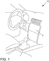
- the operating device 6 comprises a display device 1 with a display surface 2, which is arranged in the interior of the vehicle 11 such that it is clearly visible to at least one vehicle occupant, in particular the driver.
- the display surface 2 can be provided by any type of display, in particular a liquid crystal display.
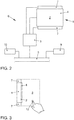
- the operating device 6 further comprises a control device 3 and an input device 4.
- the control device 3 is connected to the display device 1, with which graphic data for displaying information on the display surface 2 can be generated.
- the input device is designed as a touch-sensitive surface 4 on the display surface 2. A so-called touchscreen is thus provided.
- a film can be arranged over the display surface 2, with which the position of a touch of an actuating object 12 can be detected.
- the actuation object is in particular the fingertip of a user.
- the film can e.g. B. as a resistive touch foil, capacitive touch foil or piezoelectric foil.
- the film can be designed so that a heat flow, the z. B. starting from the fingertip 12 of a user is measured. From the temporal development of the touch of the Various inputs can be obtained from the foil. For example, in the simplest case, touching the film at a specific position can be detected and assigned to a graphic object displayed on the display surface 2. Furthermore, the length of the touch can be recorded at a specific position or within a specific area.
- An actuatable button can be displayed on the display surface 2.
- the operating device 6 comprises a proximity detection device 7.
- An actuation object 12 can be detected in a detection area 8 by means of the proximity detection device 7.
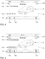
- the detection area 8 is in Fig. 3 presented in detail.
- the detection area 8 is formed in such a way that an approach of an actuation object 12 to the touch-sensitive surface 4 on the display surface 2 is detected.
- the detection area 8 forms at least one volume in front of the user interface 4.
- a cuboid is formed which completely encloses the touch-sensitive surface 4 with its side surfaces in the extension, which runs parallel to the touch-sensitive surface 4.
- the cuboid extends from the touch-sensitive surface 4 or immediately in front of the touch-sensitive surface 4 to a distance of e.g. B. about 40 cm.
- the distance of the outer boundary of the detection area 8 in front of the touch-sensitive surface 4 is chosen so that an approach to the touch-sensitive surface 4 can be detected in time so that the display on the display surface 2 can be changed early enough for the user to be able to Support input.
- the distance of the detection area 8 from the touch-sensitive surface 4 should be selected such that the actuation object 12 or another object is moved into the detection area 8 as rarely as possible if no operation of the touch-sensitive surface 4 is intended.
- the proximity detection device 7 continuously transmits the current position of an actuating object 12 in the detection area 8 to the control device 3. Depending on this signal, the control device 3 can change its state and the display on the display surface 2.
- control device 3 is coupled to a data bus 5. Via this data bus 5, the control device 3 is connected to further devices 9, 10 of the vehicle 11, about which information is to be displayed on the display surface 2 and which are to be operated by means of the operating device 6. Information can be displayed to the vehicle occupants by means of the operating device 6 and by the method. Furthermore, the vehicle occupants can operate devices 9, 10 of the vehicle 11 and control the display by means of the operating device 6.
- FIG. 4 An example of a display on the display surface 2 is shown in the display state. Messages regarding the operating status of the vehicle are displayed. For this purpose, a graphic object 15 is shown, which represents a vehicle. Furthermore, various display elements 13a are displayed, some of which are arranged in a lower bar 14. The display elements 13a indicate, for example, the number of messages present. In addition, symbols are shown which indicate a change between displays for these messages.
- control device 3 automatically changes the display on the display surface 2 to an operating state.
- the display in this operating state is in Fig. 5 reproduced.
- buttons 13b When changing from the display state to the operating state, the display type of the display elements 13a changes to a display type for buttons 13b.
- the position of the buttons 13b in the operating state corresponds to the position of the assigned display elements 13a in the display state.
- the buttons 13b can also be displayed in a different color, with a different brightness, with a different contrast and / or with a different gray level.
- the buttons 13b of the bar 14 are not only shown outlined, but also shown with a different gray level.
- the additional information area 16 which u. a. the graphic object 15 for representing the vehicle, however, remains unchanged when changing from the display state to the operating state.
- the additional information area 16 essentially comprises the entire area of the display area 2 outside the display elements 13a or the display elements 13b. Only in the case of the status information on the mobile radio reception, the current time and the current temperature displayed in the upper area of the display area 2 can a change in the display possibly result if the corresponding status information changes during the change from the display state to the operating state.
- the user can now operate one of the buttons 13b by touching or tapping.
- a corresponding signal is then transmitted to the control device 3.
- the control device 3 then converts this control signal.
- the control device 3 then automatically changes back to the display state, ie after actuation of one of the buttons 13b.
- the control device 3 only changes back to the display state when the actuation object 12 has left the detection space 8 again.
Claims (7)
- Procédé de fourniture d'un arrangement d'opération (6) dans un véhicule (11), avec lequel- des données graphiques sont générées par un arrangement de commande (3), lesquelles pilotent une surface d'affichage (2) de telle sorte que- dans un état d'opération, des boutons (13b), qui sont associés à une étape d'opération pouvant être exécutée au moyen d'un dispositif d'entrée (4), sont affichés,- dans un état d'affichage, des éléments d'affichage (13a) associés aux boutons (13b) sont représentés, lesquels ne sont associés à aucune étape d'opération pouvant être exécutée au moyen du dispositif d'entrée (4), et- dans un état d'affichage et d'opération, des informations supplémentaires sont représentées séparément des éléments d'affichage (13a) et des boutons (13b),- une approche d'un objet vers le dispositif d'entrée (4) est détectée et- lors de l'approche d'un objet d'actionnement (12) vers le dispositif d'entrée (4), l'arrangement de commande (3) change de l'état d'affichage à l'état d'opération et- lors du changement de l'état d'affichage à l'état d'opération, le mode de représentation des éléments d'affichage (13a) change dans un mode de représentation des boutons (13b), la représentation des informations supplémentaires reste en revanche inchangée, caractérisé en ce que- l'arrangement de commande (3), après l'actionnement d'un bouton (13b), change automatiquement de l'état d'opération à l'état d'affichage.
- Procédé selon la revendication 1, caractérisé en ce que lors du changement de l'état d'affichage à l'état d'opération, la représentation sur l'ensemble de la surface d'affichage (2), qui n'est pas adoptée par les éléments d'affichage (13b) dans l'état d'affichage et n'est pas adoptée par les boutons (13b) dans l'état d'opération, reste inchangée.
- Procédé selon la revendication 1 ou 2, caractérisé en ce que dans l'état d'affichage, les éléments d'affichage (13b) sont affichés dans la même zone de la surface d'affichage (2) que les boutons (13b) associés.
- Procédé selon l'une des revendications précédentes, caractérisé en ce que lors du changement de l'état d'affichage à l'état d'opération, les éléments d'affichage (13a) destinés à être représentés en tant que boutons (13b) sont représentés avec une autre luminosité, avec un autre contraste, dans une autre couleur et/ou avec un autre niveau de gris.
- Procédé selon l'une des revendications précédentes, caractérisé en ce que lors du changement de l'état d'affichage à l'état d'opération, les éléments d'affichage (13a) destinés à être représentés en tant que boutons (13b) sont pourvus d'une bordure.
- Arrangement d'opération (6) pour un véhicule, comprenant- un dispositif d'entrée (4),- un arrangement d'affichage (1) doté d'une surface d'affichage (2),- un dispositif de détection d'approche (7) destiné à détecter la position d'un objet d'actionnement devant ou sur la surface d'affichage (2),- un arrangement de commande (3), qui est connecté au dispositif d'entrée (4) et à l'arrangement d'affichage (1) et au moyen duquel peuvent être générées des données graphiques, lesquelles pilotent la surface d'affichage (2) de telle sorte que- dans un état d'opération, des boutons (13b), qui sont associés à une étape d'opération pouvant être exécutée au moyen du dispositif d'entrée (4), sont affichés,- dans un état d'affichage, des éléments d'affichage (13a) associés aux boutons (13b) sont représentés, lesquels ne sont associés à aucune étape d'opération pouvant être exécutée au moyen du dispositif d'entrée (4), et- dans un état d'affichage et d'opération, des informations supplémentaires sont représentées séparément des éléments d'affichage (13a) et des boutons (13b), et- lors de l'approche d'un objet d'actionnement (12) vers le dispositif d'entrée (4), l'arrangement de commande (3) changeant de l'état d'affichage à l'état d'opération et
lors du changement de l'état d'affichage à l'état d'opération, des données graphiques peuvent être générées au moyen de l'arrangement de commande (3), lesquelles pilotent la surface d'affichage (2) de telle sorte que le mode de représentation des éléments d'affichage (13a) change dans un mode de représentation des boutons (13b), la représentation des informations supplémentaires reste en revanche inchangée,
caractérisé en ce que- l'arrangement de commande (3) est conçu pour, après l'actionnement d'un bouton (13b), changer automatiquement de l'état d'opération à l'état d'affichage. - Véhicule équipé d'un arrangement d'opération (6) selon la revendication 6.
Applications Claiming Priority (2)
| Application Number | Priority Date | Filing Date | Title |
|---|---|---|---|
| DE102012002271A DE102012002271A1 (de) | 2012-02-04 | 2012-02-04 | Verfahren zum Bereitstellen einer Bedienvorrichtung in einem Fahrzeug und Bedienvorrichtung für ein Fahrzeug |
| PCT/EP2013/051747 WO2013113731A1 (fr) | 2012-02-04 | 2013-01-30 | Procédé de fourniture d'un dispositif de commande dans un véhicule et dispositif de commande pour un véhicule |
Publications (2)
| Publication Number | Publication Date |
|---|---|
| EP2809541A1 EP2809541A1 (fr) | 2014-12-10 |
| EP2809541B1 true EP2809541B1 (fr) | 2020-06-24 |
Family
ID=47683709
Family Applications (1)
| Application Number | Title | Priority Date | Filing Date |
|---|---|---|---|
| EP13703552.3A Active EP2809541B1 (fr) | 2012-02-04 | 2013-01-30 | Procédé de fourniture d'un dispositif de commande dans un véhicule et dispositif de commande pour un véhicule |
Country Status (4)
| Country | Link |
|---|---|
| EP (1) | EP2809541B1 (fr) |
| DE (1) | DE102012002271A1 (fr) |
| ES (1) | ES2808401T3 (fr) |
| WO (1) | WO2013113731A1 (fr) |
Families Citing this family (1)
| Publication number | Priority date | Publication date | Assignee | Title |
|---|---|---|---|---|
| DE102013226167A1 (de) * | 2013-12-17 | 2015-06-18 | Lemförder Electronic GmbH | Verfahren und Vorrichtung zum Versetzen einer elektronischen Anzeigevorrichtung in einen sicheren Zustand und Steuervorrichtung zum Steuern einer elektronischen Anzeigevorrichtung |
Citations (1)
| Publication number | Priority date | Publication date | Assignee | Title |
|---|---|---|---|---|
| DE102009048043A1 (de) * | 2008-10-15 | 2010-04-22 | Volkswagen Ag | Multifunktionsanzeige- und Bediensystem sowie Verfahren zum Steuern eines solchen Systems mit optimierter grafischer Bediendarstellung |
Family Cites Families (7)
| Publication number | Priority date | Publication date | Assignee | Title |
|---|---|---|---|---|
| DE19941956B4 (de) | 1999-09-03 | 2006-12-14 | Volkswagen Ag | Multifunktionsbedienelement mit einem Display |
| DE102006032118B4 (de) | 2006-07-12 | 2022-03-03 | Volkswagen Ag | Kombiinstrument für ein Kraftfahrzeug und Kraftfahrzeug |
| DE102007039442A1 (de) | 2007-08-21 | 2009-02-26 | Volkswagen Ag | Verfahren zum Anzeigen von Informationen in einem Fahrzeug und Anzeigeeinrichtung für ein Fahrzeug |
| DE102007039444A1 (de) | 2007-08-21 | 2009-02-26 | Volkswagen Ag | Verfahren zum Anzeigen von Informationen in einem Kraftfahrzeug und Anzeigeeinrichtung für ein Kraftfahrzeug |
| DE102007039445A1 (de) | 2007-08-21 | 2009-02-26 | Volkswagen Ag | Verfahren zum Anzeigen von Informationen in einem Kraftfahrzeug für einen Bedienzustand und einen Anzeigezustand und Anzeigeeinrichtung |
| DE102009019561A1 (de) * | 2009-04-30 | 2010-11-04 | Volkswagen Ag | Verfahren zum Anzeigen von Informationen in einem Kraftfahrzeug und Anzeigeeinrichtung |
| DE102009051202A1 (de) | 2009-10-29 | 2011-05-12 | Volkswagen Ag | Verfahren zum Betreiben einer Bedienvorrichtung und Bedienvorrichtung |
-
2012
- 2012-02-04 DE DE102012002271A patent/DE102012002271A1/de not_active Withdrawn
-
2013
- 2013-01-30 WO PCT/EP2013/051747 patent/WO2013113731A1/fr active Application Filing
- 2013-01-30 ES ES13703552T patent/ES2808401T3/es active Active
- 2013-01-30 EP EP13703552.3A patent/EP2809541B1/fr active Active
Patent Citations (1)
| Publication number | Priority date | Publication date | Assignee | Title |
|---|---|---|---|---|
| DE102009048043A1 (de) * | 2008-10-15 | 2010-04-22 | Volkswagen Ag | Multifunktionsanzeige- und Bediensystem sowie Verfahren zum Steuern eines solchen Systems mit optimierter grafischer Bediendarstellung |
Also Published As
| Publication number | Publication date |
|---|---|
| WO2013113731A1 (fr) | 2013-08-08 |
| ES2808401T3 (es) | 2021-02-26 |
| DE102012002271A1 (de) | 2013-08-08 |
| EP2809541A1 (fr) | 2014-12-10 |
Similar Documents
| Publication | Publication Date | Title |
|---|---|---|
| EP2766211B1 (fr) | Procédé de mise à disposition d'un dispositif de commande d'utilisateur, en particulier dans un véhicule, et dispositif de commande d'utilisateur pour un véhicule | |
| EP2350799B1 (fr) | Procédé et dispositif d'affichage d'informations ordonnées sous forme de liste | |
| WO2008138638A1 (fr) | Dispositif d'affichage et de commande multifonction et procédé permettant de faire fonctionner un dispositif d'affichage et de commande multifonction avec une meilleure commande de sélection | |
| EP3114554B1 (fr) | Procédé et dispositif pour mettre à disposition une interface utilisateur graphique dans un véhicule | |
| DE102009036371A1 (de) | Verfahren und Vorrichtung zum Bereitstellen einer Benutzerschnittstelle | |
| EP2485913B1 (fr) | Procede et afficheur pour afficher des informations | |
| EP2246214B1 (fr) | Procédé et dispositif d'affichage d'informations ordonnées dans des listes | |
| EP2766208B1 (fr) | Procédé d'affichage d'informations en particulier dans un véhicule et système d'affichage pour un véhicule | |
| DE102010012239B4 (de) | Bedienungs- und Anzeigevorrichtung eines Kraftfahrzeugs | |
| DE102013000069B4 (de) | Kraftfahrzeug-Bedienschnittstelle mit einem Bedienelement zum Erfassen einer Bedienhandlung | |
| EP2675648A2 (fr) | Procédé et dispositif pour l'affichage d'états de fonctionnement de dispositifs du véhicule | |
| EP2943866B1 (fr) | Procédé et dispositif permettant de fournir une interface utilisateur dans un véhicule | |
| EP2344356A1 (fr) | Procédé et dispositif d'affichage d'informations, en particulier dans un véhicule | |
| EP2809541B1 (fr) | Procédé de fourniture d'un dispositif de commande dans un véhicule et dispositif de commande pour un véhicule | |
| EP2750916B1 (fr) | Procédé de fourniture d'un dispositif de commande dans un véhicule, ainsi que dispositif de commande pour un véhicule | |
| EP2885153B1 (fr) | Procédé de mise en place d'un dispositif de réglage dans un véhicule et dispositif de réglage pour véhicule | |
| EP2703205B1 (fr) | Procédé d'affichage et de commande de groupes fonctionnels et/ou de fonctions ainsi que dispositif d'affichage et de commande | |
| DE102013001382A1 (de) | Anzeigesystem und Verfahren zum blickrichtungsabhängigen Betreiben eines Anzeigesystems | |
| EP2917062B1 (fr) | Procédé d'affichage d'informations dans un véhicule et dispositif de commande de l'affichage | |
| DE102012016110A1 (de) | Verfahren zum Bereitstellen einer Bedienvorrichtung in einem Fahrzeug und Bedienvorrichtung hierfür | |
| DE102013007329A1 (de) | Verfahren zum Betreiben einer Bedienvorrichtung in einem Fahrzeug | |
| EP2107456B1 (fr) | Sélection de modes d'affichage SKINS pour un système d'info-spectacle | |
| DE102012024516A1 (de) | Instrumententafel für ein Fahrzeug, Baukastensystem für eine Instrumententafel eines Fahrzeugs sowie Verfahren zum Anzeigen von Information in einem Fahrzeug |
Legal Events
| Date | Code | Title | Description |
|---|---|---|---|
| PUAI | Public reference made under article 153(3) epc to a published international application that has entered the european phase |
Free format text: ORIGINAL CODE: 0009012 |
|
| 17P | Request for examination filed |
Effective date: 20140904 |
|
| AK | Designated contracting states |
Kind code of ref document: A1 Designated state(s): AL AT BE BG CH CY CZ DE DK EE ES FI FR GB GR HR HU IE IS IT LI LT LU LV MC MK MT NL NO PL PT RO RS SE SI SK SM TR |
|
| AX | Request for extension of the european patent |
Extension state: BA ME |
|
| RIN1 | Information on inventor provided before grant (corrected) |
Inventor name: HOFMANN, GUSTAV Inventor name: HAHN, ALEXANDER Inventor name: BUDZYNSKI, TOBIAS Inventor name: PETERSEN, SOENKE Inventor name: KUHN, MATHIAS Inventor name: JUN, MI-RAN |
|
| DAX | Request for extension of the european patent (deleted) | ||
| STAA | Information on the status of an ep patent application or granted ep patent |
Free format text: STATUS: EXAMINATION IS IN PROGRESS |
|
| 17Q | First examination report despatched |
Effective date: 20190522 |
|
| GRAP | Despatch of communication of intention to grant a patent |
Free format text: ORIGINAL CODE: EPIDOSNIGR1 |
|
| STAA | Information on the status of an ep patent application or granted ep patent |
Free format text: STATUS: GRANT OF PATENT IS INTENDED |
|
| INTG | Intention to grant announced |
Effective date: 20200319 |
|
| GRAS | Grant fee paid |
Free format text: ORIGINAL CODE: EPIDOSNIGR3 |
|
| GRAA | (expected) grant |
Free format text: ORIGINAL CODE: 0009210 |
|
| STAA | Information on the status of an ep patent application or granted ep patent |
Free format text: STATUS: THE PATENT HAS BEEN GRANTED |
|
| AK | Designated contracting states |
Kind code of ref document: B1 Designated state(s): AL AT BE BG CH CY CZ DE DK EE ES FI FR GB GR HR HU IE IS IT LI LT LU LV MC MK MT NL NO PL PT RO RS SE SI SK SM TR |
|
| REG | Reference to a national code |
Ref country code: GB Ref legal event code: FG4D Free format text: NOT ENGLISH |
|
| REG | Reference to a national code |
Ref country code: CH Ref legal event code: EP |
|
| REG | Reference to a national code |
Ref country code: DE Ref legal event code: R096 Ref document number: 502013014837 Country of ref document: DE |
|
| REG | Reference to a national code |
Ref country code: AT Ref legal event code: REF Ref document number: 1283551 Country of ref document: AT Kind code of ref document: T Effective date: 20200715 |
|
| REG | Reference to a national code |
Ref country code: IE Ref legal event code: FG4D Free format text: LANGUAGE OF EP DOCUMENT: GERMAN |
|
| PG25 | Lapsed in a contracting state [announced via postgrant information from national office to epo] |
Ref country code: LT Free format text: LAPSE BECAUSE OF FAILURE TO SUBMIT A TRANSLATION OF THE DESCRIPTION OR TO PAY THE FEE WITHIN THE PRESCRIBED TIME-LIMIT Effective date: 20200624 Ref country code: NO Free format text: LAPSE BECAUSE OF FAILURE TO SUBMIT A TRANSLATION OF THE DESCRIPTION OR TO PAY THE FEE WITHIN THE PRESCRIBED TIME-LIMIT Effective date: 20200924 Ref country code: GR Free format text: LAPSE BECAUSE OF FAILURE TO SUBMIT A TRANSLATION OF THE DESCRIPTION OR TO PAY THE FEE WITHIN THE PRESCRIBED TIME-LIMIT Effective date: 20200925 Ref country code: FI Free format text: LAPSE BECAUSE OF FAILURE TO SUBMIT A TRANSLATION OF THE DESCRIPTION OR TO PAY THE FEE WITHIN THE PRESCRIBED TIME-LIMIT Effective date: 20200624 Ref country code: SE Free format text: LAPSE BECAUSE OF FAILURE TO SUBMIT A TRANSLATION OF THE DESCRIPTION OR TO PAY THE FEE WITHIN THE PRESCRIBED TIME-LIMIT Effective date: 20200624 |
|
| REG | Reference to a national code |
Ref country code: LT Ref legal event code: MG4D |
|
| PG25 | Lapsed in a contracting state [announced via postgrant information from national office to epo] |
Ref country code: HR Free format text: LAPSE BECAUSE OF FAILURE TO SUBMIT A TRANSLATION OF THE DESCRIPTION OR TO PAY THE FEE WITHIN THE PRESCRIBED TIME-LIMIT Effective date: 20200624 Ref country code: BG Free format text: LAPSE BECAUSE OF FAILURE TO SUBMIT A TRANSLATION OF THE DESCRIPTION OR TO PAY THE FEE WITHIN THE PRESCRIBED TIME-LIMIT Effective date: 20200924 Ref country code: RS Free format text: LAPSE BECAUSE OF FAILURE TO SUBMIT A TRANSLATION OF THE DESCRIPTION OR TO PAY THE FEE WITHIN THE PRESCRIBED TIME-LIMIT Effective date: 20200624 Ref country code: LV Free format text: LAPSE BECAUSE OF FAILURE TO SUBMIT A TRANSLATION OF THE DESCRIPTION OR TO PAY THE FEE WITHIN THE PRESCRIBED TIME-LIMIT Effective date: 20200624 |
|
| REG | Reference to a national code |
Ref country code: NL Ref legal event code: MP Effective date: 20200624 |
|
| PG25 | Lapsed in a contracting state [announced via postgrant information from national office to epo] |
Ref country code: AL Free format text: LAPSE BECAUSE OF FAILURE TO SUBMIT A TRANSLATION OF THE DESCRIPTION OR TO PAY THE FEE WITHIN THE PRESCRIBED TIME-LIMIT Effective date: 20200624 Ref country code: NL Free format text: LAPSE BECAUSE OF FAILURE TO SUBMIT A TRANSLATION OF THE DESCRIPTION OR TO PAY THE FEE WITHIN THE PRESCRIBED TIME-LIMIT Effective date: 20200624 |
|
| PG25 | Lapsed in a contracting state [announced via postgrant information from national office to epo] |
Ref country code: PT Free format text: LAPSE BECAUSE OF FAILURE TO SUBMIT A TRANSLATION OF THE DESCRIPTION OR TO PAY THE FEE WITHIN THE PRESCRIBED TIME-LIMIT Effective date: 20201026 Ref country code: EE Free format text: LAPSE BECAUSE OF FAILURE TO SUBMIT A TRANSLATION OF THE DESCRIPTION OR TO PAY THE FEE WITHIN THE PRESCRIBED TIME-LIMIT Effective date: 20200624 Ref country code: SM Free format text: LAPSE BECAUSE OF FAILURE TO SUBMIT A TRANSLATION OF THE DESCRIPTION OR TO PAY THE FEE WITHIN THE PRESCRIBED TIME-LIMIT Effective date: 20200624 Ref country code: RO Free format text: LAPSE BECAUSE OF FAILURE TO SUBMIT A TRANSLATION OF THE DESCRIPTION OR TO PAY THE FEE WITHIN THE PRESCRIBED TIME-LIMIT Effective date: 20200624 |
|
| PG25 | Lapsed in a contracting state [announced via postgrant information from national office to epo] |
Ref country code: IS Free format text: LAPSE BECAUSE OF FAILURE TO SUBMIT A TRANSLATION OF THE DESCRIPTION OR TO PAY THE FEE WITHIN THE PRESCRIBED TIME-LIMIT Effective date: 20201024 Ref country code: PL Free format text: LAPSE BECAUSE OF FAILURE TO SUBMIT A TRANSLATION OF THE DESCRIPTION OR TO PAY THE FEE WITHIN THE PRESCRIBED TIME-LIMIT Effective date: 20200624 Ref country code: SK Free format text: LAPSE BECAUSE OF FAILURE TO SUBMIT A TRANSLATION OF THE DESCRIPTION OR TO PAY THE FEE WITHIN THE PRESCRIBED TIME-LIMIT Effective date: 20200624 |
|
| REG | Reference to a national code |
Ref country code: ES Ref legal event code: FG2A Ref document number: 2808401 Country of ref document: ES Kind code of ref document: T3 Effective date: 20210226 |
|
| REG | Reference to a national code |
Ref country code: DE Ref legal event code: R097 Ref document number: 502013014837 Country of ref document: DE |
|
| PG25 | Lapsed in a contracting state [announced via postgrant information from national office to epo] |
Ref country code: DK Free format text: LAPSE BECAUSE OF FAILURE TO SUBMIT A TRANSLATION OF THE DESCRIPTION OR TO PAY THE FEE WITHIN THE PRESCRIBED TIME-LIMIT Effective date: 20200624 |
|
| PLBE | No opposition filed within time limit |
Free format text: ORIGINAL CODE: 0009261 |
|
| STAA | Information on the status of an ep patent application or granted ep patent |
Free format text: STATUS: NO OPPOSITION FILED WITHIN TIME LIMIT |
|
| 26N | No opposition filed |
Effective date: 20210325 |
|
| PG25 | Lapsed in a contracting state [announced via postgrant information from national office to epo] |
Ref country code: SI Free format text: LAPSE BECAUSE OF FAILURE TO SUBMIT A TRANSLATION OF THE DESCRIPTION OR TO PAY THE FEE WITHIN THE PRESCRIBED TIME-LIMIT Effective date: 20200624 Ref country code: MC Free format text: LAPSE BECAUSE OF FAILURE TO SUBMIT A TRANSLATION OF THE DESCRIPTION OR TO PAY THE FEE WITHIN THE PRESCRIBED TIME-LIMIT Effective date: 20200624 |
|
| REG | Reference to a national code |
Ref country code: CH Ref legal event code: PL |
|
| PG25 | Lapsed in a contracting state [announced via postgrant information from national office to epo] |
Ref country code: LU Free format text: LAPSE BECAUSE OF NON-PAYMENT OF DUE FEES Effective date: 20210130 |
|
| REG | Reference to a national code |
Ref country code: BE Ref legal event code: MM Effective date: 20210131 |
|
| PG25 | Lapsed in a contracting state [announced via postgrant information from national office to epo] |
Ref country code: CH Free format text: LAPSE BECAUSE OF NON-PAYMENT OF DUE FEES Effective date: 20210131 Ref country code: LI Free format text: LAPSE BECAUSE OF NON-PAYMENT OF DUE FEES Effective date: 20210131 |
|
| PG25 | Lapsed in a contracting state [announced via postgrant information from national office to epo] |
Ref country code: IE Free format text: LAPSE BECAUSE OF NON-PAYMENT OF DUE FEES Effective date: 20210130 |
|
| REG | Reference to a national code |
Ref country code: AT Ref legal event code: MM01 Ref document number: 1283551 Country of ref document: AT Kind code of ref document: T Effective date: 20210130 |
|
| PG25 | Lapsed in a contracting state [announced via postgrant information from national office to epo] |
Ref country code: AT Free format text: LAPSE BECAUSE OF NON-PAYMENT OF DUE FEES Effective date: 20210130 |
|
| PG25 | Lapsed in a contracting state [announced via postgrant information from national office to epo] |
Ref country code: BE Free format text: LAPSE BECAUSE OF NON-PAYMENT OF DUE FEES Effective date: 20210131 |
|
| PGFP | Annual fee paid to national office [announced via postgrant information from national office to epo] |
Ref country code: FR Payment date: 20230124 Year of fee payment: 11 Ref country code: ES Payment date: 20230228 Year of fee payment: 11 Ref country code: CZ Payment date: 20230130 Year of fee payment: 11 |
|
| PG25 | Lapsed in a contracting state [announced via postgrant information from national office to epo] |
Ref country code: HU Free format text: LAPSE BECAUSE OF FAILURE TO SUBMIT A TRANSLATION OF THE DESCRIPTION OR TO PAY THE FEE WITHIN THE PRESCRIBED TIME-LIMIT; INVALID AB INITIO Effective date: 20130130 |
|
| PGFP | Annual fee paid to national office [announced via postgrant information from national office to epo] |
Ref country code: IT Payment date: 20230120 Year of fee payment: 11 Ref country code: GB Payment date: 20230124 Year of fee payment: 11 Ref country code: DE Payment date: 20230131 Year of fee payment: 11 |
|
| P01 | Opt-out of the competence of the unified patent court (upc) registered |
Effective date: 20230523 |
|
| PG25 | Lapsed in a contracting state [announced via postgrant information from national office to epo] |
Ref country code: CY Free format text: LAPSE BECAUSE OF FAILURE TO SUBMIT A TRANSLATION OF THE DESCRIPTION OR TO PAY THE FEE WITHIN THE PRESCRIBED TIME-LIMIT Effective date: 20200624 |
|
| REG | Reference to a national code |
Ref country code: DE Ref legal event code: R079 Ref document number: 502013014837 Country of ref document: DE Free format text: PREVIOUS MAIN CLASS: B60K0037060000 Ipc: B60K0035100000 |
|
| PGFP | Annual fee paid to national office [announced via postgrant information from national office to epo] |
Ref country code: ES Payment date: 20240213 Year of fee payment: 12 |