EP2809416B1 - Device for separating two immiscible fluids of different densities by centrifugation - Google Patents
Device for separating two immiscible fluids of different densities by centrifugation Download PDFInfo
- Publication number
- EP2809416B1 EP2809416B1 EP13702469.1A EP13702469A EP2809416B1 EP 2809416 B1 EP2809416 B1 EP 2809416B1 EP 13702469 A EP13702469 A EP 13702469A EP 2809416 B1 EP2809416 B1 EP 2809416B1
- Authority
- EP
- European Patent Office
- Prior art keywords
- longitudinal
- downstream
- overflow
- stage
- radial
- Prior art date
- Legal status (The legal status is an assumption and is not a legal conclusion. Google has not performed a legal analysis and makes no representation as to the accuracy of the status listed.)
- Active
Links
Images


Classifications
-
- B—PERFORMING OPERATIONS; TRANSPORTING
- B01—PHYSICAL OR CHEMICAL PROCESSES OR APPARATUS IN GENERAL
- B01D—SEPARATION
- B01D17/00—Separation of liquids, not provided for elsewhere, e.g. by thermal diffusion
- B01D17/02—Separation of non-miscible liquids
- B01D17/0217—Separation of non-miscible liquids by centrifugal force
-
- B—PERFORMING OPERATIONS; TRANSPORTING
- B01—PHYSICAL OR CHEMICAL PROCESSES OR APPARATUS IN GENERAL
- B01D—SEPARATION
- B01D19/00—Degasification of liquids
- B01D19/0042—Degasification of liquids modifying the liquid flow
- B01D19/0052—Degasification of liquids modifying the liquid flow in rotating vessels, vessels containing movable parts or in which centrifugal movement is caused
Definitions
- the present invention relates to the field of the separation of immiscible fluids of different densities.
- It can be applied in particular to the problems of the separation of oil and water in oil emulsions, whether in the field of oil production, refining or depollution. It can also be applied to the separation of fats in the field of housing, to the extraction of free gases in one or more liquids, to the treatment of rainwater or to the production of olive oil. In particular, it can be applied to the phase separation of an emulsion which consists of a majority fluid, called carrier fluid, in which drops of a secondary fluid are present.
- gravity separators in which the emulsion is introduced at one end of a reservoir so that, after a sufficient residence time, the drops of the secondary fluid of the emulsion rise. or descend depending on whether their density is lower or higher than that of the carrier fluid. This creates at the end of the reservoir two superimposed layers of the two fluids, the lightest above and the heavier below, which are pumped by appropriate means.
- Gravity separators have the major drawback of requiring very long separation times. It has been evaluated that it takes for example a time of 5 minutes for a drop of oil of diameter equal to 200 micrometers, of density 0.85, to rise by a height of 1 m in the fresh water and calm at 20 ° C.
- gravity separators are bulky, heavy and expensive. They can not be moved or embarked on light and fast platforms, such as hovercrafts whose use is particularly adapted to the treatment of oil spills in areas of difficult access such as swamps.
- spin separators with centrifugal effect, which allow separation times much shorter than the gravity separators, such as fixed cyclones, rotating cyclones and centrifuges.
- these rotating separators are generally complex and are also very heavy, bulky and very expensive. They are therefore not suitable to be moved or shipped.
- a centrifugal separator is in particular described in the patent published under No. WO95 / 26223 .
- This separator comprises a rotary drum delimiting a compartment having an axial inlet of an emulsion at one end and in which are arranged, on a first length, radially extending longitudinal vanes, then, for a second length, a porous cylindrical body of coalescence formed by coils of coiled meshes or layers of mesh.
- This drum comprises, downstream of this compartment, annular weirs for liquid extraction, separately, and axial passages for the evacuation of the separated liquids.
- This separator has in particular the drawbacks of being very limited as regards the ratios between the densities of the liquids of the emulsion to be treated and the volumetric ratios of the liquids in the emulsion to be treated and to foul quickly.
- centrifugal separator is also described in the patent published under No. 93/25294.
- This separator comprises a frustoconical rotary drum delimiting a compartment having an axial inlet of an emulsion at its smallest end and comprises, downstream of this compartment, annular weirs for liquid extraction, separately, and axial passages for the evacuation of separated liquids.
- annular weirs for liquid extraction, separately, and axial passages for the evacuation of separated liquids.
- longitudinal pallets extending radially, whose object is to allow an axial alignment of the emulsion.
- these fins have the disadvantage of generating significant shear during rotation of the drum and a circumferential threshing of the emulsion, contrary to the desired purpose of liquid separation.
- the present invention aims to improve separators centrifugal effect.
- a device for separating immiscible fluids of different densities of an emulsion containing at least one liquid which comprises a longitudinal rotary drum having a longitudinal axis of rotation.
- the drum comprises internally longitudinally from upstream to downstream and between at least one upstream inlet and downstream outlets a solid rotation stage, a migration and coalescence stage and an extraction stage.
- the solid rotation stage comprises at least one chamber in which is arranged at least one longitudinal inner circumferential drive wall in solid rotation defining at least one flow space communicating with said inlet.
- the migration and coalescence stage comprises at least one chamber in which is arranged at least one longitudinal internal partition of circumferential drive in solid rotation, delimiting a plurality of longitudinal flow channels respectively having an upstream end communicating with said space d flow of said solid rotation stage and a downstream end connected to said outlets, said partition comprising at least one longitudinal partition delimiting at least one of said longitudinal channels and extending to said downstream end.
- the extraction stage comprises at least one liquid spillway comprising a spill threshold turned on the side of said axis of rotation and extending along a longitudinal flow space communicating, upstream, with said longitudinal channels of water. stage of migration and coalescence by at least a longitudinal passage and comprising, downstream, a downstream liquid discharge space communicating with the longitudinal flow space and connected to one of said downstream outlets.
- the upstream inlet - opens - into a portion of said flow space of the solid rotation stage, located near the axis of rotation.
- the drum is equipped with a radial inner wall separating the chamber from the solid rotation stage and the chamber of the migration and coalescence stage, this radial inner wall being provided with through passages.
- the device may comprise an axial duct or an axial tube integral with the drum for bringing the emulsion into the central part of the chamber of the solid rotation stage.
- the partitioning of the migration and coalescence stage can define, from upstream to downstream, a plurality of longitudinal channels distributed circumferentially.
- the partitioning of the migration and coalescence stage can define, from upstream to downstream, an intermediate plurality of longitudinal channels distributed circumferentially and radially, followed by a plurality of downstream longitudinal channels distributed circumferentially, each channel communicating with several of the channels. of the first plurality of channels.
- the partitioning of the migration and coalescence stage can define, from upstream to downstream, an upstream plurality of circumferentially distributed longitudinal channels, followed by an intermediate plurality of circumferentially and radially distributed longitudinal channels of which several channels communicate with each channel.
- the extraction stage may comprise a weir whose discharge threshold is annular and a downstream annular discharge space communicating with a peripheral downstream outlet.
- the extraction stage may comprise a weir whose discharge threshold is close to the axis of rotation, the downstream discharge space of this weir being connected to a downstream liquid outlet and a downstream gas outlet.
- the device may include circumferential drive bulkheads located in the downstream flow space.
- Circumferential drive fins may be placed in the longitudinal flow space.
- the extraction stage may comprise a lighter liquid inner weir whose longitudinal flow space communicates with the migration and coalescence stage by an inner longitudinal passage and an outer weir of a heavier liquid whose longitudinal flow space communicates with the migration and coalescence stage by an outer longitudinal passage further from said axis of rotation than the inner longitudinal passage.
- the discharge threshold of the outer weir may be further from said axis of rotation than the discharge threshold of the inner weir.
- the outfall spillway threshold may be located radially between the outer longitudinal passage and the spillway threshold of the inner weir.
- the inner weir and the outer weir may be connected to different downstream outlets through different downstream discharge spaces.
- Circumferential drive fins may be placed in the intermediate flow space connecting the outer passage and the outer weir.
- Said circumferential drive fins may have an inner edge located outside and away from the discharge threshold of the outer weir.
- Circumferential drive fins may be placed in the longitudinal flow space of the inner weir.
- Circumferential drive fins may be placed in the downstream discharge space of the inner weir.
- Circumferential drive fins may be placed in the downstream discharge space of the outer weir.
- the device may comprise a support of said drum, having a portion provided with outlet ducts, at least one of these outlet ducts communicating with a downstream liquid outlet of said drum.
- the device may comprise a rotary fluid seal formed between the drum and the support, on the extraction stage side, this rotary joint comprising two fixed radial walls integral with the support and delimiting an open space radially inwards and a rotary radial wall integral with the drum engaged at a distance between said fixed radial rings, this open space being connected to the chamber of the migration and coalescence stage, the rotating radial wall being provided on both sides with blades; circumferential drive.
- the drum may be equipped with a radial inner wall separating the chamber of the migration and coalescence stage and the extraction stage, this radial inner wall having at least one longitudinal communication passage between these stages.
- the device may include a conduit connecting the inner space of the inner weir and the inner space of the outer weir.
- the device may include a conduit for connecting the inner space of the inner weir to the outside and a conduit for connecting the inner space of the outer weir to the outside.
- the device may comprise gas pressure / vacuum sources which are connected to the flow spaces of the weirs of the extraction stage, so that these pressures respectively act on the free surfaces of the liquids.
- the extraction stage can be located above the migration and coalescence stage.
- the device may also comprise an intake chamber axially connected to the central part of the chamber of the solid rotation stage, this intake chamber being fed tangentially in the direction of rotation of said drum in order to generate a rotation of the emulsion to the solid rotation stage.
- a liquid is said to be “circumferentially driven in solid rotation” when it is contained in a compartment which is off-center with respect to an axis of rotation and which extends over a limited angular sector, between walls spaced apart circumferentially, so that the compartment rotates around the axis of rotation and thus the liquid undergoes the effects of the centrifugal force.
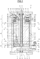
- a separation device 10 illustrated on the Figures 1 to 6 comprises a fixed support 11 with vertical axis 12, which comprises a cylindrical peripheral wall or ferrule 13, a lower radial wall 14 and an upper radial cover 15.
- This drum 16 rotating about the vertical axis 12.
- This drum 16 comprises a lower radial wall 17, disc-shaped, located at a distance above the lower radial wall 14 and provided downwardly with an axial cylindrical shaft portion 18 engaged in the lower radial wall 14 and mounted thereon by means of a bearing 19 for rotating the drum 16.
- the drum 16 is rotated by a drive motor 20 by means of a connecting means which comprises for example a pulley 21 carried by the cylindrical shaft 18, a pulley 22 carried by the motor shaft 20 and a belt 23 connecting these pulleys.
- a connecting means which comprises for example a pulley 21 carried by the cylindrical shaft 18, a pulley 22 carried by the motor shaft 20 and a belt 23 connecting these pulleys.
- the drum 16 comprises an inner axial cylindrical tube 24, of small diameter, whose lower end is secured to the wall lower radial 17 and whose upper end is engaged in the radial cover 15 and mounted on this cover by means of a bearing 25 for rotating mounting of the drum 16.
- the drum 16 comprises an axial cylindrical peripheral wall 26 located internally at a small distance from the ferrule 13, whose lower end is integral with the periphery of the lower radial wall 17 and whose upper end is located at a distance below the radial cover 15.
- the drum 16 comprises an intermediate annular inner radial wall 27, which is located on the side and away from the lower radial wall 17 and which connects the inner cylindrical tube 24 and the cylindrical peripheral wall 26.
- the lower radial wall 17 and the intermediate radial wall 27 form between them an inlet chamber 28.
- the portion of the inner cylindrical tube 24, located between the lower radial wall 17 and the intermediate radial wall 27, has radial inlet openings 29 distributed angularly and located close to the axis of rotation 12.
- the intermediate radial wall 27 has a plurality of longitudinal traversing passages 30 of communication which are for example distributed over the entire surface of the intermediate radial wall 27 ( Figures 2 and 3 ).
- a partition comprising a plurality of longitudinal inner walls 31, of circumferential drive in solid rotation, extending in planes containing the axis 12 and angularly distributed ( Figure 3 ).
- These longitudinal partitions 31 extend radially from the cylindrical peripheral wall 26 and up to a short distance from the inner cylindrical tube 24 and define therebetween a plurality of longitudinally distributed channels or longitudinal flow spaces 32.
- the portion of the axial tube 24 located between the radial wall 17 and the intermediate radial wall 27 could be eliminated.
- the internal partitioning 31 could possibly be extended as far as the axis 12 and could also be extended inside the axial tube 24, upwards beyond the intermediate radial partition 27.
- the drum 16 comprises an annular intermediate inner radial wall 34 which is situated above and at a greater distance from the intermediate radial wall 27 and below and at a distance from the radial cover 15.
- the intermediate radial wall 27 and the intermediate radial wall 34 form between them a chamber 35 and form an upstream end and a downstream end of this chamber 35.
- the intermediate radial wall 34 extends from the cylindrical peripheral wall 26, without reaching the inner cylindrical tube 24, so as to form an inner longitudinal annular passage 36 of communication surrounding the inner cylindrical tube 24.
- the intermediate radial wall 34 has a plurality of external longitudinal through-passages 37 which are arranged at a small distance from the cylindrical peripheral wall 26 and for example distributed over a circle ( Figure 4 ).
- the outer longitudinal through-passages 37 are further from the axis of rotation 12 of the drum 16 than the inner longitudinal annular passage 36.
- a partition which comprises a plurality of inner longitudinal partitions 38, of circumferential drive in solid rotation, extending in planes containing the axis 12 and angularly distributed ( figures 3 and 4 ).
- These longitudinal partitions 38 extend radially between and join the inner cylindrical tube 24 and the cylindrical peripheral wall 26 and extend longitudinally between and join the intermediate radial wall 27 and the intermediate radial wall 34. These longitudinal partitions 38 define between them a plurality of longitudinal flow channels 39.
- These longitudinal channels 39 have an upstream end on the side of the intermediate radial wall 27 and a downstream end on the side of the intermediate radial wall 34 and are distributed circumferentially.
- the number of longitudinal partitions 38 may be equal to the number of longitudinal partitions 31.
- the longitudinal partitions 38 may be arranged in the extension of the longitudinal partitions 31.
- an upper extraction stage 41 situated above the migration and coalescence stage 40.
- this extraction stage 41 comprises an inner weir 42 which comprises a longitudinal cylindrical wall 43 whose lower end is connected to the inner annular edge of the intermediate radial wall 34 and which extends upwards as far as the lid radial 15.
- annular discharge threshold 45 turned towards the axis of rotation 12 and extending along the longitudinal flow space 44.
- longitudinal annular flow space 44 In the longitudinal annular flow space 44 is arranged, optionally, a plurality of longitudinal partitions 46, circumferential drive in solid rotation, which extend in planes containing the axis 12, between the longitudinal tube 24 and the longitudinal wall 43, which are angularly distributed. These longitudinal partitions 46 extend upward the longitudinal partitions 38 of the migration and coalescence stage 40, passing through the longitudinal passage 36.
- the inner weir 42 further comprises a radial wall 47, of annular shape, whose inner edge is connected to the upper edge of the cylindrical wall 43 and whose outer edge is situated at a short distance from the cylindrical peripheral wall 26, so as to define a downstream peripheral evacuation space 48 between the radial cover 15 and the radial wall 47.
- This downstream discharge space 48 communicates internally with the longitudinal annular flow space 44 and is open radially on the side of the cylindrical peripheral wall 26 so as to form an annular downstream outlet 49.
- downstream evacuation space 48 is arranged a plurality of longitudinal fins 50, circumferential drive in solid rotation, which are arranged in planes containing the axis of rotation 12 and angularly distributed and which are carried laterally by the radial wall 47 and extend upwards to the vicinity of the lid 15. Is thus formed a self-adapted downstream centrifugal pump 50a integrated drum.
- the cylindrical peripheral wall 13 of the fixed support 11 has a through-outlet orifice 51 situated opposite the downstream discharge space 47 and extended by an external discharge pipe 52.
- a plurality of discharge orifices 51 distributed around the outlet cylindrical peripheral wall 13 could be provided.
- the extraction stage 41 also comprises an external weir 53 which is formed between the radial walls 34 and 47 and around and at a distance from the cylindrical wall 43.
- the outer weir 53 comprises a longitudinal cylindrical wall 54 located around and at a distance from the cylindrical wall 43, whose lower edge is at a distance above the intermediate radial wall 34 and whose upper edge is at a distance below the radial wall 47.
- the outer weir 53 further comprises a radial wall 55, of annular shape, which is located at a distance above the intermediate radial wall 34 and which connects the upper edge of the cylindrical peripheral wall 26 and the lower edge of the cylindrical wall 54, and a radial wall 56, of annular shape, which is located at a distance below the radial wall 47, whose inner edge is connected to the upper edge of the cylindrical wall 54 and whose outer edge is low. distance from the cylindrical peripheral wall 13 of the support 11.
- An annular intermediate flow space 57 is thus defined between the radial walls 34 and 55 and inside the upper end portion of the cylindrical peripheral wall 26, this intermediate flow space 57 communicating with the chamber 35 via the external longitudinal through-passages 37 of the radial wall 34.
- a plurality of longitudinal fins 58 disposed in planes containing the axis of rotation 12 and distributed angularly or circumferentially, these longitudinal fins 58 being connected to the cylindrical peripheral wall 26 and the walls radial 34 and 55 ( figure 5 ).
- the number of longitudinal fins 58 may be equal to the number of longitudinal partitions 38.
- the longitudinal fins 58 may be arranged in the extension of the longitudinal partitions 38.
- the longitudinal inner edges 58a of the longitudinal fins 58 are located at a distance outside the inner face of the cylindrical wall 54. According to another embodiment illustrated in FIG. figure 7 the longitudinal fins 58 are extended to the longitudinal wall 43.
- Is also defined a longitudinal annular flow space 59 between the cylindrical wall 43 and the cylindrical wall 54, which communicates with the intermediate space 57.
- the inner face of the cylindrical wall 54 forms an annular threshold spill 60 rotated about the axis of rotation 12 and extending along the longitudinal flow space 59.
- the cylindrical peripheral wall 13 of the fixed support 11 carries an annular inner radial wall 61 situated at a short distance below the radial wall 47 and at a distance from the radial wall 56 and extending to the vicinity of the cylindrical wall 43.
- the radial wall 47 is provided, on the side of the radial wall 61, radial fins 47a circumferential drive to form a rotating seal of liquid.
- a lining forming a mechanical seal could be placed between the rotating radial wall 47 and the fixed radial wall 61.
- This downstream discharge space 62 communicates with the longitudinal flow space 59 and is radially open on the side of the cylindrical peripheral wall 26 so as to form a downstream outlet 63, of annular shape.
- downstream evacuation space 62 In the downstream evacuation space 62 is arranged a plurality of longitudinal fins 64, of circumferential drive in solid rotation, which extend in planes containing the axis of rotation 12, which are angularly distributed and which are carried laterally by the radial wall 56.
- a self-adapted and integrated downstream centrifugal pump 64a In the downstream evacuation space 62 is arranged a plurality of longitudinal fins 64, of circumferential drive in solid rotation, which extend in planes containing the axis of rotation 12, which are angularly distributed and which are carried laterally by the radial wall 56.
- the cylindrical peripheral wall 13 of the fixed support 11 has a through-evacuation orifice 65 situated in front of the downstream evacuation space 62 and extended by an external evacuation pipe 66.
- a plurality of evacuation orifices 51 distributed around the outlet cylindrical peripheral wall 13 could be provided.
- the cylindrical wall 43 carries, radially, radial communication tubes or conduits 43a projecting in the longitudinal flow space 44, so as to put in communication this longitudinal flow space 44 and the longitudinal flow space 59 .
- the outer longitudinal passages 37 are farther from the axis of rotation 12 than the inner longitudinal passage 36, the discharge threshold 60 of the outer weir 53 is further from the axis of rotation 12 than the discharge threshold 45 of the inner weir 42, and that the discharge threshold 60 of the outer weir 53 is located between the through passages 37 of the radial wall 34 and the discharge threshold 45 of the inner weir 42.
- the longitudinal wall 54 of the drum 16 and the cylindrical peripheral wall 13 of the fixed support 11 is provided with a rotating fluid seal 67.
- This seal 67 comprises a central radial wall 68 carried by the longitudinal wall 54 and extending to near the cylindrical peripheral wall 13 and the radial walls 69 and 70 carried by the cylindrical peripheral wall 13, disposed between and in the vicinity respectively of the radial walls 55 and 68 and the radial walls 56 and 68.
- the central radial wall 68 is provided on its opposite faces with circumferential radial fins 68a and 68b.
- the longitudinal wall 54 has at least one through orifice 54a, of small diameter, placing in communication the intermediate flow space 57 and the internal space of the fluid seal 67.
- the integrated liquid rotary seal 67 could be replaced by gaskets forming mechanical seals.
- the fixed support 11 is equipped with an axial cylindrical feed pipe 71 which passes through the cover 15, which extends inside the cylindrical tube 24 and whose lower end is at a distance from the lower radial wall 17 of the drum 16 and is located in the region of the intermediate radial wall 27.
- the axial pipe 71 could be shortened or removed and a fixed inlet chamber communicating with the upper end of the possibly shortened axial pipe 71 or the axial tube 24 could be arranged above the radial wall fixed 15.
- This fixed intake chamber could be fed tangentially to cause a rotation of the emulsion inside the axial tube 24 in the direction of rotation of the drum, which can persist up to the stage of implementation. solid rotation 33.
- the feed could be carried out axially through the radial wall 17 and the axial shaft 18, the axial tube 24 then being obstructed in the region of the intermediate radial wall 27.
- the lid 15 of the support 11 has, in its central part, at least one through orifice 72 which communicates with the connection space between the longitudinal flow space 44 and the downstream discharge space 48 of the inner weir 42.
- the separation device 10 can operate as follows.
- the drum 16 is rotated by the motor 20 and rotates at a substantially constant speed matched.
- the emulsion E passes through the longitudinal through-passages 30 of the intermediate radial wall 27 and enters the longitudinal flow channels 39 of the chamber 35 of the migration and coalescence stage 40, in which the solid rotation is maintained. under the effect of the longitudinal partitions 38, to the intermediate radial wall 34 of the downstream end of the chamber 35.
- the light liquid L1 forms an inner cylinder having a substantially cylindrical free surface IG1 facing the axis of rotation 12 and located at a distance from the longitudinal tube 24 and the heavy liquid L2 forms an outer cylinder in contact with the cylindrical peripheral wall 26, these inner and outer cylinders of liquids L1 and L2 having a cylindrical interface IC which is located between the inner longitudinal passage 36 and the outer through passages 37 of the intermediate radial wall 34.
- the ends of the connecting tubes 43a are inside the cylindrical free surface IG1.
- the light liquid L1 passes through the inner longitudinal passage 36 of the intermediate radial wall 34, then flows longitudinally in the longitudinal flow space 44 over the discharge threshold 45 of the inner weir 42 in the form of a sheet cylindrical N1 whose surface is in the extension of the cylindrical free surface IG1 . Solid rotation can be maintained by means of longitudinal partitions 46.
- the light liquid L1 is discharged, radially outwards, into the downstream discharge space 48, then flows through the downstream outlet 49 of the drum 16, then flows through the orifice outlet 51 of the fixed support 11 and finally flows into the discharge pipe 52.
- the liquid L1 can form, in the periphery of the downstream flow space 48 and on the corresponding peripheral zone of the peripheral wall 13 of the support 11, an annular layer.
- the heavy liquid L2 passes through the outer longitudinal passages 37 of the partition 34 and enters the intermediate flow space 57. Then, the heavy liquid L2 flows radially inwards into the intermediate flow space 57, in which the solid rotation is maintained thanks to the longitudinal fins 58, at least in the periphery of this flow space 57. Then, the heavy liquid L2 flows longitudinally in the longitudinal flow space 59 on the threshold 60 of the outfall weir 53 in the form of a cylindrical sheet N2 having a cylindrical free surface IG2 formed at a distance from the outer face of the longitudinal wall 43. The pressure on the free surfaces IG1 and IG2 is the same due to the existence of the radial ducts 43a.
- the heavy liquid L2 discharges, radially outwards, into the downstream discharge space 62, then flows through the downstream outlet 63 of the drum 16, then flows through the orifice outlet 65 of the fixed support 11 and finally flows into the discharge pipe 66.
- the liquid L2 can form, in the periphery of the downstream flow space 62 and on the corresponding peripheral zone of the peripheral wall 13 of the support 11, an annular layer.
- the radial thicknesses of the plies N1 and N2 of liquids L1 and L2 on the discharge thresholds 45 and 60 depend in particular on the speed of rotation of the drum 16, the treated emulsion flow rate, the respective proportions of the liquids L1 and L2 in the emulsion E and the respective radial positions of the discharge thresholds 45 and 60. In proportion to the different other thicknesses of the liquids L1 and L2, the thicknesses of the plies N1 and N2 are small.
- the radial position of the IC interface between the light liquid L1 and the heavy liquid L2 depends mainly on the difference between the densities of the liquids L1 and L2 and the rotational speed of the drum 16, in particular for the following reasons.
- the pressures P ext of the liquid L 2 are substantially equal on either side of the radial wall 34, in the chamber 35 and in the intermediate space 57 which are connected by the communication through passages 37.
- the pressures P int are substantially equal.
- the pressure decreases along two successive curves. Between the peripheral wall 26 and the interface IC , the pressure decreases in the heavy liquid L2 from the pressure P ext , according to a pressure curve ⁇ PL2 (35). Then, between the interface IC and the free surface IG1 , the pressure decreases in the light liquid L1 to the pressure P int , according to a pressure curve ⁇ PL1 (35).
- the pressure decreases in the heavy liquid L2 from the pressure P ext to the pressure P int , according to a pressure curve ⁇ PL2 (57).
- the pressure curves ⁇ PL2 (35) , ⁇ PL1 (35) and ⁇ PL2 (57) depend on the densities of the liquids L1 and L2 and are respectively formed, substantially, by portions of concave parabolas on the side of the axis of rotation 12. Pressure curve ⁇ PL2 (57) and pressure curve ⁇ PL2 (35) follow substantially the same curvature.
- the pressure conditions are similar to those of the previous example.
- the pressure decreases in the heavy liquid L2 from the pressure P ext , according to a curve ⁇ PL2a (57) , as in the previous example.
- the pressure decreases in the heavy liquid L2 to the pressure P int according to another curve ⁇ PL2b (57).
- ⁇ PL2b curve (57) Since the flow tends to be cyclonic between the inner edges 58a of the circumferential drive fins 58 and the inner free surface IG2 as previously indicated, this decrease according to the ⁇ PL2b curve (57) is faster than the decay established according to FIG. example of figure 7 in which the solid rotation of the liquid L2 is maintained at least up to the outflow threshold 60.
- This curve ⁇ PL2b (57) is formed, substantially, by a convex hyperbola portion on the side of the axis of rotation 12.
- the outside discharge threshold 60 of the figure 8 has a diameter greater than that of the discharge threshold 60 of the example illustrated in FIG. figure 7 .
- the separation device 10 can separate liquids with selected densities in a larger range and it is then possible to separate liquids L1 and L2 having very similar densities.
- the emulsion E is fed into the supply line 71 by means of a positive displacement pump (not shown), the orifice 72 of the lid 15 is at atmospheric pressure and there is a need to have in the outlets 51 and 65 pressure loads greater than atmospheric pressure, for example in the case where these outlets 51 and 65 are connected to discharge pipes 52 and 66 generating pressure drops.
- the downstream centrifugal pumps 50a and 64a formed by the downstream vanes 50 and 64 serve to provide the liquid flow rates L1 and L2 , which come from the discharge thresholds 44 and 60 and discharge radially outwards, pressures to compensate for these losses.
- the orifice 72 of the lid 15 is connected to a vacuum pump to generate a suction vacuum, for example less than the atmospheric pressure, for sucking emulsion E.
- a vacuum pump to generate a suction vacuum, for example less than the atmospheric pressure, for sucking emulsion E.
- Downstream centrifugal pumps 50a and 64a formed by the downstream fins 50 and 64 serve to provide the flow rates of liquid L1 and L2 , which flow, the pressure loads to compensate for the suction vacuum and possibly the pressure drops of the previous example.
- the downstream flow spaces 48 and 62 can communicate directly with the atmosphere through the through-passages 51 and 65 of the peripheral wall of the support 11, with a view to discharging the L1 and L2 liquids.
- the downstream fins 50 and 58 could be removed if the emulsion E is brought under pressure and if the internal pressure is equal to the atmospheric pressure.
- the connecting conduits 43a are deleted.
- the flow space 59 is, this time, connected to a gas pressure / vacuum source 73, via a radial duct 74 passing through the longitudinal wall 54 and a radial duct 75 passing through a radial wall.
- the pressure delivered by the source 77 acts on the free surface IG1 of the liquid L1 , in the inner weir 42 and the pressure delivered by the source 73 acts on the free surface IG2 of the liquid L2 in the outer weir 53.
- the desired actual position of the IC interface can be adjusted or regulated as a function of the variations of the densities of the liquids L1 and L2 and / or as a function of the variations of the position of the IC interface which could be detected by a device of measured.
- one of the sources of pressure / depression may be atmospheric pressure. Only the other source of pressure is then adjustable or controllable.
- liquid rotary joint 67 With regard to the liquid rotary joint 67, its operation can be as follows.
- Liquid L2 from the intermediate flow space 57 is introduced through the through hole 54a. Under the effect of the radial fins 68a and 68b carried by the rotating radial wall 68 opposite the fixed radial walls 69 and 70, this liquid is held in the peripheral part of the gasket, between the walls 69 and 70, which which creates a seal between the downstream flow space 62 and the space, in the atmosphere, between the peripheral wall 13 of the support 11 and the peripheral wall 26 of the drum 16.
- a separation device 100 which differs from the separation device 10 by the structure of the partition arranged in the chamber 35 of the migration and coalescence stage 40, the other parts being equivalent.
- This partitioning comprises, in the upstream portion of the chamber 35 adjacent to the intermediate radial wall 27, a plurality of longitudinal partitions 101 and, in its downstream portion adjacent to the intermediate radial wall 34, a plurality of longitudinal partitions 102 and, in its middle longitudinal part, a plurality of longitudinal partitions 103.
- the longitudinal partitions 101 and the longitudinal partitions 102 are arranged, equivalent to the partitions 38 of the separation device 10, so as to form pluralities of longitudinal flow channels 104 and 105 distributed circumferentially.
- the longitudinal partitions 103 are arranged to form a plurality of intermediate longitudinal flow channels 106 distributed circumferentially and radially.
- the longitudinal flow channels 106 have sections smaller than the longitudinal flow channels 104 and 105 and are larger in number.
- the length of the longitudinal channels 104 may be equal to 15% of the length of the chamber 35
- the length of the longitudinal channels 106 may be equal to 40% of the length of the chamber 35
- the length of the channels longitudinal 105 may be equal to 35% of the length of the chamber 35.
- the longitudinal partitions 103 are arranged such that, in section, the longitudinal flow channels 106 form honeycombs.
- the longitudinal partitions 103 comprise longitudinal partitions 103a distributed angularly and longitudinal partitions 103b cylindrical and spaced from each other in the radial direction.
- upstream longitudinal partitions 101 Thanks to the existence of upstream longitudinal partitions 101, then intermediate longitudinal partitions 103 and downstream longitudinal partitions 102, there is a circumferential drive in solid rotation in the upstream longitudinal channels 104 and in the intermediate longitudinal channels 106 and in the channels downstream longitudinal 105, the emulsion and then the liquids L1 and L2, equivalent to what has been previously described about the separation device 10.
- a separating device 200 is shown which differs from the separating device 10 in that the outer weir 53 is omitted and the intermediate partition 34 no longer has the through-passages 37, the other parts being equivalent .
- This separation device 200 is more particularly adapted to extract an emulsion E a free gas carried by a liquid L1 in the form of bubbles.
- the liquid L1 introduced into the chamber 35 is subjected to driving in a solid rotation under the effect of the rotation of the drum 16, has a cylindrical free surface IG1 , passes to above the discharge threshold 45 of the inner weir 42 and then flows into the downstream flow space 48 to be evacuated.
- the gas extracted from the liquid L1 and present in the space between the cylindrical tube 24 and the cylindrical free surface IG1 is discharged through a plurality of orifices 72 formed in the lid 15.
- the separators that have just been described could be arranged upside down, that is to say that their separation stage could be down.
- their main axis could be inclined or horizontal.
Description
La présente invention concerne le domaine de la séparation de fluides non miscibles de densités différentes.The present invention relates to the field of the separation of immiscible fluids of different densities.
Elle peut s'appliquer en particulier aux problèmes de la séparation de l'huile et de l'eau dans les émulsions pétrolières, que ce soit dans le domaine de la production pétrolière, du raffinage ou de la dépollution. Elle peut s'appliquer également à la séparation des graisses dans le domaine de l'habitat, à l'extraction de gaz libres dans un ou des liquides, au traitement des eaux de pluie ou à la production d'huile d'olive. En particulier, elle peut s'appliquer à la séparation des phases d'une émulsion qui est constituée d'un fluide majoritaire, dit fluide porteur, dans lequel sont présentes des gouttes d'un fluide secondaire.It can be applied in particular to the problems of the separation of oil and water in oil emulsions, whether in the field of oil production, refining or depollution. It can also be applied to the separation of fats in the field of housing, to the extraction of free gases in one or more liquids, to the treatment of rainwater or to the production of olive oil. In particular, it can be applied to the phase separation of an emulsion which consists of a majority fluid, called carrier fluid, in which drops of a secondary fluid are present.
Pour réaliser cette opération, il est connu d'utiliser des séparateurs gravitaires dans lesquels on introduit l'émulsion à une extrémité d'un réservoir de telle sorte qu'après un temps de séjour suffisant, les gouttes du fluide secondaire de l'émulsion montent ou descendent selon que leur densité est inférieure ou supérieure à celle du fluide porteur. On crée ainsi en extrémité du réservoir deux couches superposées des deux fluides, le plus léger au-dessus et le plus lourd au-dessous, qui sont pompés par des moyens appropriés.To carry out this operation, it is known to use gravity separators in which the emulsion is introduced at one end of a reservoir so that, after a sufficient residence time, the drops of the secondary fluid of the emulsion rise. or descend depending on whether their density is lower or higher than that of the carrier fluid. This creates at the end of the reservoir two superimposed layers of the two fluids, the lightest above and the heavier below, which are pumped by appropriate means.
Les séparateurs gravitaires ont le défaut majeur de nécessiter des durées de séparation très importantes. Il a été évalué qu'il faut par exemple une durée de 5 minutes pour qu'une goutte d'huile de diamètre égal à 200 micromètres, de densité 0,85, s'élève d'une hauteur de 1 m dans de l'eau douce et calme à 20°C. De plus, les séparateurs gravitaires sont encombrants, lourds et chers. Ils ne peuvent donc pas être déplacés ou embarqués sur des plateformes légères et rapides, telles les hovercrafts dont l'usage est particulièrement adapté au traitement des marées noires dans des zones d'accès difficiles telles que des marécages.Gravity separators have the major drawback of requiring very long separation times. It has been evaluated that it takes for example a time of 5 minutes for a drop of oil of diameter equal to 200 micrometers, of density 0.85, to rise by a height of 1 m in the fresh water and calm at 20 ° C. In addition, gravity separators are bulky, heavy and expensive. They can not be moved or embarked on light and fast platforms, such as hovercrafts whose use is particularly adapted to the treatment of oil spills in areas of difficult access such as swamps.
Il est également connu d'utiliser des séparateurs tournants à effet centrifuge, qui permettent des durées de séparation beaucoup plus courtes que les séparateurs gravitaires, tels que des cyclones fixes, des cyclones tournants et des centrifugeuses. Dans les modes de réalisation actuels, ces séparateurs tournants sont généralement complexes et sont également très lourds, encombrants et très onéreux. Ils ne sont donc pas non plus adaptés pour être déplacés ou embarqués.It is also known to use spin separators with centrifugal effect, which allow separation times much shorter than the gravity separators, such as fixed cyclones, rotating cyclones and centrifuges. In current embodiments, these rotating separators are generally complex and are also very heavy, bulky and very expensive. They are therefore not suitable to be moved or shipped.
Un séparateur à effet centrifuge est en particulier décrit dans le brevet publié sous le N°
Un autre séparateur à effet centrifuge est également décrit dans le brevet publié sous le N° 93/25294. Ce séparateur comprend un tambour rotatif de forme tronconique délimitant un compartiment présentant une entrée axiale d'une émulsion à son extrémité la plus petite et comprend, en aval de ce compartiment, des déversoirs annulaires en vue d'une extraction des liquides, séparément, et des passages axiaux en vue de l'évacuation des liquides séparés. Dans une première partie dudit compartiment, très éloignée de son extrémité aval, sont aménagées des palettes longitudinales s'étendant radialement, dont l'objet annoncé est de permettre un alignement axial de l'émulsion. Or, ces ailettes présentent l'inconvénient d'engendrer un cisaillement important lors de la rotation du tambour et un battage circonférentiel de l'émulsion, contraire au but recherché de séparation des liquides.Another centrifugal separator is also described in the patent published under No. 93/25294. This separator comprises a frustoconical rotary drum delimiting a compartment having an axial inlet of an emulsion at its smallest end and comprises, downstream of this compartment, annular weirs for liquid extraction, separately, and axial passages for the evacuation of separated liquids. In a first part of said compartment, very far from its downstream end, are arranged longitudinal pallets extending radially, whose object is to allow an axial alignment of the emulsion. However, these fins have the disadvantage of generating significant shear during rotation of the drum and a circumferential threshing of the emulsion, contrary to the desired purpose of liquid separation.
La présente invention a pour but d'améliorer les séparateurs à effet centrifuge.The present invention aims to improve separators centrifugal effect.
Il est proposé un dispositif de séparation de fluides non miscibles de densités différentes d'une émulsion contenant au moins un liquide, qui comprend un tambour rotatif longitudinal présentant un axe longitudinal de rotation.It is proposed a device for separating immiscible fluids of different densities of an emulsion containing at least one liquid, which comprises a longitudinal rotary drum having a longitudinal axis of rotation.
Le tambour comprend intérieurement, longitudinalement d'amont en aval et entre au moins une entrée amont et des sorties aval un étage de mise en rotation solide, un étage de migration et de coalescence et un étage d'extraction.The drum comprises internally longitudinally from upstream to downstream and between at least one upstream inlet and downstream outlets a solid rotation stage, a migration and coalescence stage and an extraction stage.
L'étage de mise en rotation solide comprend au moins une chambre dans laquelle est aménagée au moins une cloison intérieure longitudinale d'entraînement circonférentiel en rotation solide délimitant au moins un espace d'écoulement communiquant avec ladite entrée.The solid rotation stage comprises at least one chamber in which is arranged at least one longitudinal inner circumferential drive wall in solid rotation defining at least one flow space communicating with said inlet.
L'étage de migration et de coalescence comprend au moins une chambre dans laquelle est aménagé au moins un cloisonnement intérieur longitudinal d'entraînement circonférentiel en rotation solide, délimitant une pluralité de canaux longitudinaux d'écoulement présentant respectivement une extrémité amont communiquant avec ledit espace d'écoulement dudit étage de mise en rotation solide et une extrémité aval reliée auxdites sorties, ledit cloisonnement comprenant au moins une cloison longitudinale délimitant au moins l'un desdits canaux longitudinaux et s'étendant jusqu'à ladite extrémité aval.The migration and coalescence stage comprises at least one chamber in which is arranged at least one longitudinal internal partition of circumferential drive in solid rotation, delimiting a plurality of longitudinal flow channels respectively having an upstream end communicating with said space d flow of said solid rotation stage and a downstream end connected to said outlets, said partition comprising at least one longitudinal partition delimiting at least one of said longitudinal channels and extending to said downstream end.
L'étage d'extraction comprend au moins un déversoir de liquide comprenant un seuil de déversement tourné du côté dudit axe de rotation et s'étendant le long d'un espace d'écoulement longitudinal communiquant, en amont, avec lesdits canaux longitudinaux de l'étage de migration et de coalescence par au moins un passage longitudinal et comprenant, en aval, un espace aval d'évacuation de liquide communiquant avec l'espace d'écoulement longitudinal et relié à l'une desdites sorties aval.The extraction stage comprises at least one liquid spillway comprising a spill threshold turned on the side of said axis of rotation and extending along a longitudinal flow space communicating, upstream, with said longitudinal channels of water. stage of migration and coalescence by at least a longitudinal passage and comprising, downstream, a downstream liquid discharge space communicating with the longitudinal flow space and connected to one of said downstream outlets.
L'entrée amont - débouche- dans une partie dudit espace d'écoulement de l'étage de mise en rotation solide, située proche de l'axe de rotation.The upstream inlet - opens - into a portion of said flow space of the solid rotation stage, located near the axis of rotation.
Le tambour est équipé d'une paroi intérieure radiale séparant la chambre de l'étage de mise en rotation solide et la chambre de l'étage de migration et de coalescence, cette paroi intérieure radiale étant munie de passages traversants.The drum is equipped with a radial inner wall separating the chamber from the solid rotation stage and the chamber of the migration and coalescence stage, this radial inner wall being provided with through passages.
Le dispositif peut comprendre un conduit axial ou un tube axial solidaire du tambour pour l'amenée de l'émulsion dans la partie centrale de la chambre de l'étage de mise en rotation solide.The device may comprise an axial duct or an axial tube integral with the drum for bringing the emulsion into the central part of the chamber of the solid rotation stage.
Le cloisonnement de l'étage de migration et de coalescence peut définir, d'amont en aval, une pluralité de canaux longitudinaux répartis circonférentiellement.The partitioning of the migration and coalescence stage can define, from upstream to downstream, a plurality of longitudinal channels distributed circumferentially.
Le cloisonnement de l'étage de migration et de coalescence peut définir, d'amont en aval, une pluralité intermédiaire de canaux longitudinaux répartis circonférentiellement et radialement, suivie d'une pluralité aval de canaux longitudinaux répartis circonférentiellement dont chaque canal communique avec plusieurs des canaux de la première pluralité de canaux.The partitioning of the migration and coalescence stage can define, from upstream to downstream, an intermediate plurality of longitudinal channels distributed circumferentially and radially, followed by a plurality of downstream longitudinal channels distributed circumferentially, each channel communicating with several of the channels. of the first plurality of channels.
Le cloisonnement de l'étage de migration et de coalescence peut définir, d'amont en aval, une pluralité amont de canaux longitudinaux répartis circonférentiellement, suivie d'une pluralité intermédiaire de canaux longitudinaux répartis circonférentiellement et radialement dont plusieurs canaux communiquent avec chaque canal de la pluralité amont de canaux, suivie d'une pluralité aval de canaux longitudinaux répartis circonférentiellement dont chaque canal communique avec plusieurs des canaux de la première pluralité de canaux.The partitioning of the migration and coalescence stage can define, from upstream to downstream, an upstream plurality of circumferentially distributed longitudinal channels, followed by an intermediate plurality of circumferentially and radially distributed longitudinal channels of which several channels communicate with each channel. the upstream plurality of channels, followed by a downstream plurality of circumferentially distributed longitudinal channels of which each channel communicates with several of the channels of the first plurality of channels.
L'étage d'extraction peut comprendre un déversoir dont le seuil de déversement est annulaire et un espace aval d'évacuation annulaire communiquant avec une sortie aval périphérique.The extraction stage may comprise a weir whose discharge threshold is annular and a downstream annular discharge space communicating with a peripheral downstream outlet.
L'étage d'extraction peut comprendre un déversoir dont le seuil de déversement est proche de l'axe de rotation, l'espace aval d'évacuation de ce déversoir étant relié à une sortie aval de liquide et à une sortie aval de gaz.The extraction stage may comprise a weir whose discharge threshold is close to the axis of rotation, the downstream discharge space of this weir being connected to a downstream liquid outlet and a downstream gas outlet.
Le dispositif peut comprendre des cloisons d'entraînement circonférentiel placées dans l'espace aval d'écoulement.The device may include circumferential drive bulkheads located in the downstream flow space.
Des ailettes d'entraînement circonférentiel peuvent être placées dans l'espace d'écoulement longitudinal.Circumferential drive fins may be placed in the longitudinal flow space.
L'étage d'extraction peut comprendre un déversoir intérieur de liquide plus léger dont l'espace d'écoulement longitudinal communique avec l'étage de migration et de coalescence par un passage longitudinal intérieur et un déversoir extérieur d'un liquide plus lourd dont l'espace d'écoulement longitudinal communique avec l'étage de migration et de coalescence par un passage longitudinal extérieur plus éloigné dudit axe de rotation que le passage longitudinal intérieur.The extraction stage may comprise a lighter liquid inner weir whose longitudinal flow space communicates with the migration and coalescence stage by an inner longitudinal passage and an outer weir of a heavier liquid whose longitudinal flow space communicates with the migration and coalescence stage by an outer longitudinal passage further from said axis of rotation than the inner longitudinal passage.
Le seuil de déversement du déversoir extérieur peut être plus éloigné dudit axe de rotation que le seuil de déversement du déversoir intérieur.The discharge threshold of the outer weir may be further from said axis of rotation than the discharge threshold of the inner weir.
Le seuil de déversement du déversoir extérieur peut être situé, dans le sens radial, entre le passage longitudinal extérieur et le seuil de déversement du déversoir intérieur.The outfall spillway threshold may be located radially between the outer longitudinal passage and the spillway threshold of the inner weir.
Le déversoir intérieur et le déversoir extérieur peuvent être reliés à des sorties aval différentes par l'intermédiaire d'espaces aval d'évacuation différents.The inner weir and the outer weir may be connected to different downstream outlets through different downstream discharge spaces.
Des ailettes d'entraînement circonférentiel peuvent être placées dans l'espace intermédiaire d'écoulement reliant le passage extérieur et le déversoir extérieur.Circumferential drive fins may be placed in the intermediate flow space connecting the outer passage and the outer weir.
Lesdites ailettes d'entraînement circonférentiel peuvent présenter un bord intérieur situé à l'extérieur et à distance du seuil de déversement du déversoir extérieur.Said circumferential drive fins may have an inner edge located outside and away from the discharge threshold of the outer weir.
Des ailettes d'entraînement circonférentiel peuvent être placées dans l'espace d'écoulement longitudinal du déversoir intérieur.Circumferential drive fins may be placed in the longitudinal flow space of the inner weir.
Des ailettes d'entraînement circonférentiel peuvent être placées dans l'espace aval d'évacuation du déversoir intérieur.Circumferential drive fins may be placed in the downstream discharge space of the inner weir.
Des ailettes d'entraînement circonférentiel peuvent être placées dans l'espace aval d'évacuation du déversoir extérieur.Circumferential drive fins may be placed in the downstream discharge space of the outer weir.
Le dispositif peut comprendre un support dudit tambour, présentant une partie munie de conduits de sortie, au moins l'un de ces conduits de sortie communiquant avec une sortie aval de liquide dudit tambour.The device may comprise a support of said drum, having a portion provided with outlet ducts, at least one of these outlet ducts communicating with a downstream liquid outlet of said drum.
Le dispositif peut comprendre un joint tournant de fluide formé entre le tambour et le support, du côté de l'étage d'extraction, ce joint tournant comprenant deux parois radiales fixes solidaires du support et délimitant un espace ouvert radialement vers l'intérieur et une paroi radiale tournante solidaire du tambour engagée à distance entre lesdites bagues radiales fixes, cet espace ouvert étant relié à la chambre de l'étage de migration et de coalescence, la paroi radiale tournante étant munie de part et d'autre d'ailettes d'entraînement circonférentiel.The device may comprise a rotary fluid seal formed between the drum and the support, on the extraction stage side, this rotary joint comprising two fixed radial walls integral with the support and delimiting an open space radially inwards and a rotary radial wall integral with the drum engaged at a distance between said fixed radial rings, this open space being connected to the chamber of the migration and coalescence stage, the rotating radial wall being provided on both sides with blades; circumferential drive.
Le tambour peut être équipé d'une paroi intérieure radiale séparant la chambre de l'étage de migration et de coalescence et l'étage d'extraction, cette paroi intérieure radiale présentant au moins un passage longitudinal de communication entre ces étages.The drum may be equipped with a radial inner wall separating the chamber of the migration and coalescence stage and the extraction stage, this radial inner wall having at least one longitudinal communication passage between these stages.
Le dispositif peut comprendre un conduit reliant l'espace interne du déversoir intérieur et l'espace interne du déversoir extérieur.The device may include a conduit connecting the inner space of the inner weir and the inner space of the outer weir.
Le dispositif peut comprendre un conduit pour relier l'espace interne du déversoir intérieur à l'extérieur et un conduit pour relier l'espace interne du déversoir extérieur à l'extérieur.The device may include a conduit for connecting the inner space of the inner weir to the outside and a conduit for connecting the inner space of the outer weir to the outside.
Le dispositif peut comprendre des sources de pression/dépression de gaz qui sont reliées aux espaces d'écoulement des déversoirs de l'étage d'extraction, de façon que ces pressions agissent respectivement sur les surfaces libres des liquides.The device may comprise gas pressure / vacuum sources which are connected to the flow spaces of the weirs of the extraction stage, so that these pressures respectively act on the free surfaces of the liquids.
L'étage d'extraction peut être situé au-dessus de l'étage de migration et de coalescence.The extraction stage can be located above the migration and coalescence stage.
Le dispositif peut également comprendre une chambre d'admission reliée axialement à la partie centrale de la chambre de l'étage de mise en rotation solide, cette chambre d'admission étant alimentée tangentiellement dans le sens de la rotation dudit tambour afin d'engendrer une rotation de l'émulsion jusqu'à l'étage de mise en rotation solide.The device may also comprise an intake chamber axially connected to the central part of the chamber of the solid rotation stage, this intake chamber being fed tangentially in the direction of rotation of said drum in order to generate a rotation of the emulsion to the solid rotation stage.
Des dispositifs de séparation de fluides d'une émulsion contenant au moins un fluide et leurs modes de fonctionnement vont maintenant être décrits de façon non limitative en référence aux dessins dans lesquels :
- La
figure 1 représente une coupe verticale d'un dispositif de séparation de deux liquides d'une émulsion, selon deux plans décalés angulairement repérés sur lafigure 2 par la référence I-I, l'axe du dispositif de séparation étant placé verticalement ; - La
figure 2 représente une coupe radiale selon II-II, orientée vers le haut, d'un étage de mise en rotation solide du dispositif de séparation de lafigure 1 ; - - La
figure 3 représente une coupe radiale selon III-III, orientée vers le bas, d'un étage de migration et de coalescence du dispositif de séparation de lafigure 1 ; - - La
figure 4 représente une coupe radiale selon IV-IV, orientée vers le haut, de l'étage de migration et de coalescence du dispositif de séparation de lafigure 1 ; - - La
figure 5 représente une coupe radiale selon IV-IV, orientée vers le haut, d'un étage d'extraction du dispositif de séparation de lafigure 1 ; - - La
figure 6 représente une coupe verticale agrandie de la partie supérieure du dispositif de séparation de lafigure 1 , incluant l'étage d'extraction ; - - La
figure 7 illustre des courbes de pression dans le dispositif de lafigure 1 ; - - La
figure 8 illustre des autres courbes de pression dans le dispositif de lafigure 1 ; - - La
figure 9 représente une demi coupe verticale de la partie supérieure d'une variante de réalisation du dispositif de séparation de lafigure 1 ; - - La
figure 10 représente une coupe verticale d'un autre dispositif de séparation, selon X-X de lafigure 11 ; - - La
figure 11 représente une coupe radiale selon XI-XI d'un étage de migration et de coalescence du dispositif de séparation de lafigure 10 , selon une première variante de réalisation ; - - La
figure 12 représente une coupe radiale correspondante de l'étage de migration et de coalescence du dispositif de séparation de lafigure 10 , selon une seconde variante de réalisation ; - - La
figure 13 représente une coupe verticale agrandie correspondante d'une partie de l'étage de migration et de coalescence du dispositif de séparation de lafigure 10 ; - - La
figure 14 représente une coupe verticale d'un autre dispositif de séparation, selon XIV-XIV de lafigure 15 ; et - - La
figure 15 représente une coupe radiale selon XV-XV d'un étage de migration et de coalescence du dispositif de séparation de lafigure 10 , selon une première variante de réalisation.
- The
figure 1 represents a vertical section of a device for separating two liquids from an emulsion, according to two offset planes angularly spotted on thefigure 2 by the reference II, the axis of the separating device being placed vertically; - The
figure 2 represents an upwardly directed radial section II-II of a solid rotation stage of the separation device of thefigure 1 ; - - The
figure 3 represents a downwardly directed III-III radial section of a migration and coalescence stage of the separation device of thefigure 1 ; - - The
figure 4 represents an IV-IV radial section, facing upwards, of the migration and coalescence stage of the separation device of thefigure 1 ; - - The
figure 5 represents an IV-IV radial section, facing upwards, of an extraction stage of the separation device of thefigure 1 ; - - The
figure 6 represents an enlarged vertical section of the upper part of the separation device of thefigure 1 , including the extraction stage; - - The
figure 7 illustrates pressure curves in the device of thefigure 1 ; - - The
figure 8 illustrates other pressure curves in the device of thefigure 1 ; - - The
figure 9 represents a half vertical section of the upper part of an embodiment variant of the separation device of thefigure 1 ; - - The
figure 10 represents a vertical section of another separation device, according to XX of thefigure 11 ; - - The
figure 11 represents a radial section along XI-XI of a migration and coalescence stage of the separation device of thefigure 10 according to a first variant embodiment; - - The
figure 12 represents a corresponding radial section of the migration and coalescence stage of the separation device of thefigure 10 according to a second variant embodiment; - - The
figure 13 represents a corresponding enlarged vertical section of a portion of the migration and coalescence stage of the separation device of thefigure 10 ; - - The
figure 14 represents a vertical section of another separation device, according to XIV-XIV of thefigure 15 ; and - - The
figure 15 represents a radial section along XV-XV of a stage of migration and coalescence of the separation device of thefigure 10 according to a first variant embodiment.
Tout d'abord, il convient de définir ce que l'on va entendre par « liquide entraîné circonférentiellement en rotation solide » dans la description qui suit. Un liquide est dit « entraîné circonférentiellement en rotation solide » lorsqu'il est contenu dans un compartiment qui est décentré par rapport à un axe de rotation et qui s'étend sur un secteur angulaire limité, entre des cloisons espacées circonférentiellement, de telle sorte que le compartiment tourne autour de l'axe de rotation et qu'ainsi le liquide subit les effets de la force centrifuge.First, it is necessary to define what is meant by "circumferentially driven fluid in solid rotation" in the description which follows. A liquid is said to be "circumferentially driven in solid rotation" when it is contained in a compartment which is off-center with respect to an axis of rotation and which extends over a limited angular sector, between walls spaced apart circumferentially, so that the compartment rotates around the axis of rotation and thus the liquid undergoes the effects of the centrifugal force.
Un dispositif de séparation 10 illustré sur les
A l'intérieur du support 11 est disposé un tambour rotatif 16 tournant autour de l'axe vertical 12. Ce tambour 16 comprend une paroi radiale inférieure 17, en forme de disque, située à distance au-dessus de la paroi radiale inférieure 14 et munie vers le bas d'une portion d'arbre cylindrique axial 18 engagée dans la paroi radiale inférieure 14 et montée sur cette dernière par l'intermédiaire d'un roulement 19 de montage tournant du tambour 16.Inside the
Le tambour 16 est entraîné en rotation par un moteur d'entraînement 20 par l'intermédiaire d'un moyen de liaison qui comprend par exemple une poulie 21 portée par l'arbre cylindrique 18, une poulie 22 portée par l'arbre du moteur 20 et une courroie 23 reliant ces poulies.The
Le tambour 16 comprend un tube cylindrique axial intérieur 24, de petit diamètre, dont l'extrémité inférieure est solidaire de la paroi radiale inférieure 17 et dont l'extrémité supérieure est engagée dans le couvercle radial 15 et montée sur ce couvercle par l'intermédiaire d'un roulement 25 de montage tournant du tambour 16.The
Le tambour 16 comprend une paroi périphérique cylindrique axiale 26 située intérieurement à faible distance de la virole 13, dont l'extrémité inférieure est solidaire de la périphérie de la paroi radiale inférieure 17 et dont l'extrémité supérieure est située à distance au-dessous du couvercle radial 15.The
Le tambour 16 comprend une paroi radiale intérieure intermédiaire 27, de forme annulaire, qui est située du côté et à distance de la paroi radiale inférieure 17 et qui relie le tube cylindrique intérieur 24 et la paroi périphérique cylindrique 26. La paroi radiale inférieure 17 et la paroi radiale intermédiaire 27 forment entre elles une chambre d'entrée 28.The
La portion du tube cylindrique intérieur 24, située entre la paroi radiale inférieure 17 et la paroi radiale intermédiaire 27, présente des ouvertures d'entrée radiale 29 réparties angulairement et situées proches de l'axe de rotation 12. La paroi radiale intermédiaire 27 présente une pluralité de passages traversants longitudinaux 30 de communication qui sont par exemple répartis sur toute la surface de la paroi radiale intermédiaire 27 (
Dans la chambre d'entrée 28 est aménagé un cloisonnement comprenant une pluralité de cloisons intérieures longitudinales 31, d'entraînement circonférentiel en rotation solide, s'étendant dans des plans contenant l'axe 12 et réparties angulairement (
Dans une variante de réalisation, la partie du tube axial 24 située entre la paroi radiale 17 et la paroi radiale intermédiaire 27 pourrait être supprimée.In an alternative embodiment, the portion of the
Notamment dans le cas ci-dessus, le cloisonnement intérieur 31 pourrait être prolongé éventuellement jusqu'à l'axe 12 et pourrait aussi être prolongé à l'intérieur du tube axial 24, vers le haut au-delà de la cloison radiale intermédiaire 27.In particular in the case above, the
Est ainsi défini, entre la paroi radiale inférieure 17 et la paroi radiale intérieure 27 et dans la chambre 28, un étage inférieur de mise en rotation solide 33.Is thus defined, between the lower
Le tambour 16 comprend une paroi radiale intérieure intermédiaire 34, de forme annulaire, qui est située au-dessus et à plutôt grande distance de la paroi radiale intermédiaire 27 et au-dessous et à distance du couvercle radial 15. La paroi radiale intermédiaire 27 et la paroi radiale intermédiaire 34 forment entre elles une chambre 35 et forment une extrémité amont et une extrémité aval de cette chambre 35. La paroi radiale intermédiaire 34 s'étend à partir de la paroi périphérique cylindrique 26, sans atteindre le tube cylindrique intérieur 24, de façon à former un passage annulaire longitudinal intérieur 36 de communication entourant le tube cylindrique intérieur 24.The
La paroi radiale intermédiaire 34 présente une pluralité de passages traversants longitudinaux extérieurs 37 qui sont aménagés à faible distance de la paroi périphérique cylindrique 26 et par exemple répartis sur un cercle (
Dans la chambre 35 est aménagé un cloisonnement qui comprend une pluralité de cloisons intérieures longitudinales 38, d'entraînement circonférentiel en rotation solide, s'étendant dans des plans contenant l'axe 12 et réparties angulairement (
Ces cloisons longitudinales 38 s'étendent radialement entre, et rejoignent, le tube cylindrique intérieur 24 et la paroi périphérique cylindrique 26 et s'étendent longitudinalement entre, et rejoignent, la paroi radiale intermédiaire 27 et la paroi radiale intermédiaire 34. Ces cloisons longitudinales 38 définissent entre elles une pluralité de canaux longitudinaux d'écoulement 39.These
Ces canaux longitudinaux 39 présentent une extrémité amont du côté de la paroi radiale intermédiaire 27 et une extrémité aval du côté de la paroi radiale intermédiaire 34 et sont répartis circonférentiellement. Le nombre de cloisons longitudinales 38 peut être égal au nombre de cloisons longitudinales 31. Les cloisons longitudinales 38 peuvent être disposées dans le prolongement des cloisons longitudinales 31.These
Est ainsi défini, entre la paroi radiale intermédiaire 27 et la paroi radiale intermédiaire 34 et dans la chambre 35, un étage intermédiaire de migration et de coalescence 40.Is thus defined, between the intermediate
Entre la paroi radiale intermédiaire 34 et le couvercle radial supérieur 15 est défini un étage supérieur d'extraction 41 situé au-dessus de l'étage de migration et de coalescence 40.Between the intermediate
Comme illustré plus particulièrement sur la
Est ainsi défini un espace annulaire longitudinal d'écoulement 44 entre le tube cylindrique longitudinal 24 et la paroi cylindrique longitudinale 43, qui communique avec la chambre 35 par le passage annulaire longitudinal 36.Is thus defined a longitudinal annular space of
Ainsi, la face intérieure de la paroi cylindrique 43 forme un seuil annulaire de déversement 45 tourné du côté de l'axe de rotation 12 et s'étendant le long de l'espace d'écoulement longitudinal 44.Thus, the inner face of the
Dans l'espace annulaire longitudinal d'écoulement 44 est aménagée, de façon optionnelle, une pluralité de cloisons longitudinales 46, d'entraînement circonférentiel en rotation solide, qui s'étendent dans des plans contenant l'axe 12, entre le tube longitudinal 24 et la paroi longitudinale 43, et qui sont réparties angulairement. Ces cloisons longitudinales 46 prolongent vers le haut les cloisons longitudinales 38 de l'étage de migration et de coalescence 40, en traversant le passage longitudinal 36.In the longitudinal
Le déversoir intérieur 42 comprend en outre une paroi radiale 47, de forme annulaire, dont le bord intérieur est relié au bord supérieur de la paroi cylindrique 43 et dont le bord extérieur est situé à faible distance de la paroi périphérique cylindrique 26, de façon à définir un espace aval périphérique d'évacuation 48 entre le couvercle radial 15 et la paroi radiale 47. Cet espace aval d'évacuation 48 communique intérieurement avec l'espace annulaire longitudinal d'écoulement 44 et est ouvert radialement du côté de la paroi périphérique cylindrique 26 de façon à former une sortie aval annulaire 49.The
Dans l'espace aval d'évacuation 48 est aménagée une pluralité d'ailettes longitudinales 50, d'entraînement circonférentiel en rotation solide, qui sont disposées dans des plans contenant l'axe de rotation 12 et réparties angulairement et qui sont portées latéralement par la paroi radiale 47 et s'étendent vers le haut jusqu'à proximité du couvercle 15. Est ainsi formée une pompe centrifuge aval auto-adaptée 50a intégrée au tambour.In the
La paroi périphérique cylindrique 13 du support fixe 11 présente un orifice traversant d'évacuation 51 situé en face de l'espace aval d'évacuation 47 et prolongé par une conduite d'évacuation extérieure 52. Plusieurs orifices d'évacuation 51 répartis autour de la paroi périphérique cylindrique 13 pourraient être prévus.The cylindrical
L'étage d'extraction 41 comprend également un déversoir extérieur 53 qui est formé entre les parois radiales 34 et 47 et autour et à distance de la paroi cylindrique 43.The
Le déversoir extérieur 53 comprend une paroi cylindrique longitudinale 54 située autour et à distance de la paroi cylindrique 43, dont le bord inférieur est à distance au-dessus de la paroi radiale intermédiaire 34 et dont le bord supérieur est à distance au-dessous de la paroi radiale 47.The
Le déversoir extérieur 53 comprend en outre une paroi radiale 55, de forme annulaire, qui est située à distance au-dessus de la paroi radiale intermédiaire 34 et qui relie le bord supérieur de la paroi périphérique cylindrique 26 et le bord inférieur de la paroi cylindrique 54, ainsi qu'une paroi radiale 56, de forme annulaire, qui est située à distance au-dessous de la paroi radiale 47, dont le bord intérieur est relié au bord supérieur de la paroi cylindrique 54 et dont le bord extérieur est à faible distance de la paroi périphérique cylindrique 13 du support 11.The
Est ainsi défini un espace intermédiaire d'écoulement 57, de forme annulaire, entre les parois radiales 34 et 55 et à l'intérieur de la partie d'extrémité supérieure de la paroi périphérique cylindrique 26, cet espace intermédiaire d'écoulement 57 communiquant avec la chambre 35 par l'intermédiaire des passages traversants longitudinaux extérieurs 37 de la paroi radiale 34.An annular
Dans l'espace intermédiaire d'écoulement 57 est aménagée une pluralité d'ailettes longitudinales 58 disposées dans des plans contenant l'axe de rotation 12 et réparties angulairement ou circonférentiellement, ces ailettes longitudinales 58 étant reliées à la paroi périphérique cylindrique 26 et aux parois radiales 34 et 55 (
Selon la variante de réalisation illustrée sur les
Est également défini un espace longitudinal d'écoulement 59, de forme annulaire, entre la paroi cylindrique 43 et la paroi cylindrique 54, qui communique avec l'espace intermédiaire d'écoulement 57. La face intérieure de la paroi cylindrique 54 forme un seuil annulaire de déversement 60 tourné du côté de l'axe de rotation 12 et s'étendant le long de l'espace longitudinal d'écoulement 59.Is also defined a longitudinal
La paroi périphérique cylindrique 13 du support fixe 11 porte une paroi radiale intérieure 61, de forme annulaire, située à faible distance au-dessous de la paroi radiale 47 et à distance de la paroi radiale 56 et s'étendant jusqu'à proximité de la paroi cylindrique 43. La paroi radiale 47 est munie, du côté de la paroi radiale 61, d'ailettes radiales 47a d'entraînement circonférentiel pour former un joint tournant de liquide. Selon une variante de réalisation, une garniture formant un joint mécanique pourrait être placée entre la paroi radiale tournante 47 et la paroi radiale fixe 61.The cylindrical
Est également défini un espace périphérique aval d'évacuation 62, de forme annulaire, entre la paroi radiale 56 et la paroi radiale 61. Cet espace aval d'évacuation 62 communique avec l'espace longitudinal d'écoulement 59 et est ouvert radialement du côté de la paroi périphérique cylindrique 26 de façon à former une sortie aval 63, de forme annulaire.Is also defined an annular downstream
Dans l'espace aval d'évacuation 62 est aménagée une pluralité d'ailettes longitudinales 64, d'entraînement circonférentiel en rotation solide, qui s'étendent dans des plans contenant l'axe de rotation 12, qui sont réparties angulairement et qui sont portées latéralement par la paroi radiale 56. Est ainsi formée une pompe centrifuge aval auto-adaptée et intégrée 64a.In the
La paroi périphérique cylindrique 13 du support fixe 11 présente un orifice traversant d'évacuation 65 situé en face de l'espace aval d'évacuation 62 et prolongé par une conduite d'évacuation extérieure 66. Plusieurs orifices d'évacuation 51 répartis autour de la paroi périphérique cylindrique 13 pourraient être prévus.The cylindrical
La paroi cylindrique 43 porte, radialement, des tubes ou conduits radiaux de communication 43a en saillie dans l'espace longitudinal d'écoulement 44, de façon à mettre en communication cet espace longitudinal d'écoulement 44 et l'espace longitudinal d'écoulement 59.The
Il résulte de ce qui précède, radialement, que les passages longitudinaux extérieurs 37 sont plus éloignés de l'axe de rotation 12 que le passage longitudinal intérieur 36, que le seuil de déversement 60 du déversoir extérieur 53 est plus éloigné de l'axe de rotation 12 que le seuil de déversement 45 du déversoir intérieur 42, et que le seuil de déversement 60 du déversoir extérieur 53 est situé entre les passages traversants 37 de la paroi radiale 34 et le seuil de déversement 45 du déversoir intérieur 42.As a result of the above, radially, the outer
Dans l'espace entre les parois radiales 55 et 56, la paroi longitudinale 54 du tambour 16 et la paroi périphérique cylindrique 13 du support fixe 11 est aménagé un joint tournant de fluide 67. Ce joint 67 comprend une paroi radiale centrale 68 portée par la paroi longitudinale 54 et s'étendant jusqu'à proximité de la paroi périphérique cylindrique 13 et des parois radiales 69 et 70 portées par la paroi périphérique cylindrique 13, disposées entre et à proximité respectivement des parois radiales 55 et 68 et des parois radiales 56 et 68. La paroi radiale centrale 68 est munie sur ses faces opposées d'ailettes radiales 68a et 68b d'entraînement circonférentiel. La paroi longitudinale 54 présente au moins un orifice traversant 54a, de petit diamètre, mettant en communication l'espace intermédiaire d'écoulement 57 et l'espace interne du joint de fluide 67. Selon une variante de réalisation, le joint tournant liquide intégré 67 pourrait être remplacé par des garnitures formant des joints mécaniques.In the space between the
Le support fixe 11 est équipé d'une conduite cylindrique axiale d'amenée 71 qui traverse le couvercle 15, qui s'étend à l'intérieur du tube cylindrique 24 et dont l'extrémité inférieure est à distance de la paroi radiale inférieure 17 du tambour 16 et est située dans la zone de la paroi radiale intermédiaire 27.The fixed
Selon une variante de réalisation, la conduite axiale 71 pourrait être raccourcie ou supprimée et une chambre d'admission fixe communiquant avec l'extrémité supérieure de la conduite axiale 71 éventuellement raccourcie ou du tube axiale 24 pourrait être aménagée au-dessus de la paroi radiale fixe 15. Cette chambre d'admission fixe pourrait être alimentée tangentiellement afin d'engendrer une rotation de l'émulsion à l'intérieur du tube axial 24 dans la sens de rotation du tambour, pouvant persister jusqu'à l'étage de mise en rotation solide 33.According to an alternative embodiment, the
Selon une autre variante de réalisation, l'amenée pourrait être réalisée axialement au travers de la paroi radiale 17 et de l'arbre axial 18, le tube axial 24 étant alors obstrué dans la zone de la paroi radiale intermédiaire 27.According to another variant embodiment, the feed could be carried out axially through the
Le couvercle 15 du support 11 présente, dans sa partie centrale, au moins un orifice traversant 72 qui communique avec l'espace de liaison entre l'espace d'écoulement longitudinal 44 et l'espace aval d'évacuation 48 du déversoir intérieur 42.The
Le dispositif de séparation 10 peut fonctionner de la manière suivante.The
Le tambour 16 est entraîné en rotation grâce au moteur 20 et tourne à une vitesse substantiellement constante adaptée.The
Une émulsion E contenant un liquide léger L1 et un liquide lourd L2, à séparer, pénètre dans le conduit fixe d'amenée 71 et est introduite, au travers des ouvertures d'entrée radiale 29 du tube tournant 24, dans les espaces d'écoulement 32 de la chambre 28 de l'étage de mise en rotation solide 33, dans laquelle elle est mise en rotation solide sous l'effet des cloisons longitudinales 31.An emulsion E containing a light liquid L1 and a heavy liquid L2, to be separated, enters the fixed
Ensuite, l'émulsion E traverse les passages traversants longitudinaux 30 de la paroi radiale intermédiaire 27 et pénètre dans les canaux longitudinaux d'écoulement 39 de la chambre 35 de l'étage de migration et de coalescence 40, dans laquelle la rotation solide est maintenue sous l'effet des cloisons longitudinales 38, jusqu'à la paroi radiale intermédiaire 34 d'extrémité aval de la chambre 35.Then, the emulsion E passes through the longitudinal through-
Lors de l'écoulement longitudinal d'amont en aval, sous l'effet de la force centrifuge résultant de la rotation du tambour 16 et dans chacun des canaux longitudinaux d'écoulement 39, le liquide léger L1 tend à se déplacer vers l'axe de rotation 12 et le liquide lourd L2 tend à se déplacer vers la paroi périphérique 26, de telle sorte que les liquides L1 et L2 se séparent avant d'atteindre la paroi radiale intermédiaire 34 d'extrémité aval de l'étage de migration et de coalescence 40.During the longitudinal flow from upstream to downstream, under the effect of the centrifugal force resulting from the rotation of the
Il en résulte qu'au moins dans la partie terminale de la chambre 35, le liquide léger L1 forme un cylindre intérieur présentant une surface libre substantiellement cylindrique IG1 tournée du côté de l'axe de rotation 12 et située à distance du tube longitudinal 24 et que le liquide lourd L2 forme un cylindre extérieur en contact avec la paroi périphérique cylindrique 26, ces cylindres intérieur et extérieur de liquides L1 et L2 présentant une interface cylindrique IC qui est située entre le passage longitudinal intérieur 36 et les passages traversants extérieurs 37 de la paroi radiale intermédiaire 34. Les extrémités des tubes de liaison 43a sont à l'intérieur de la surface libre cylindrique IG1. As a result, at least in the end portion of the
Ensuite, le liquide léger L1 traverse le passage longitudinal intérieur 36 de la paroi radiale intermédiaire 34, puis s'écoule longitudinalement dans l'espace longitudinal d'écoulement 44 sur le seuil de déversement 45 du déversoir intérieur 42 sous la forme d'une nappe cylindrique N1 dont la surface est dans le prolongement de la surface libre cylindrique IG1. La rotation solide peut être maintenue grâce aux cloisons longitudinales 46.Then, the light liquid L1 passes through the inner
Ensuite, le liquide léger L1 se déverse, radialement vers l'extérieur, dans l'espace aval d'évacuation 48, puis s'écoule au travers de la sortie aval 49 du tambour 16, puis s'écoule au travers de l'orifice de sortie 51 du support fixe 11 et enfin s'écoule dans la conduite d'évacuation 52. Sous certaines conditions, le liquide L1 peut former, dans la périphérie de l'espace aval d'écoulement 48 et sur la zone périphérique correspondante de la paroi périphérique 13 du support 11, une couche annulaire.Then, the light liquid L1 is discharged, radially outwards, into the
Parallèlement, le liquide lourd L2 traverse les passages longitudinaux extérieurs 37 de la cloison 34 et pénètre dans l'espace intermédiaire d'écoulement 57. Puis, le liquide lourd L2 s'écoule radialement vers l'intérieur dans l'espace intermédiaire d'écoulement 57, dans lequel la rotation solide est maintenue grâce aux ailettes longitudinales 58, au moins dans la périphérie de cet espace d'écoulement 57. Puis, le liquide lourd L2 s'écoule longitudinalement dans l'espace longitudinal d'écoulement 59 sur le seuil de déversement 60 du déversoir extérieur 53 sous la forme d'une nappe cylindrique N2 présentant une surface libre cylindrique IG2 formée à distance de la face extérieure de la paroi longitudinale 43. La pression sur les surfaces libres IG1 et IG2 est la même du fait de l'existence des conduits radiaux 43a.Meanwhile, the heavy liquid L2 passes through the outer
Ensuite, le liquide lourd L2 se déverse, radialement vers l'extérieur, dans l'espace aval d'évacuation 62, puis s'écoule au travers de la sortie aval 63 du tambour 16, puis s'écoule au travers de l'orifice de sortie 65 du support fixe 11 et enfin s'écoule dans la conduite d'évacuation 66. Sous certaines conditions, le liquide L2 peut former, dans la périphérie de l'espace aval d'écoulement 62 et sur la zone périphérique correspondante de la paroi périphérique 13 du support 11, une couche annulaire.Then, the heavy liquid L2 discharges, radially outwards, into the
Les épaisseurs radiales des nappes N1 et N2 de liquides L1 et L2 sur les seuils de déversement 45 et 60, dépendent notamment de la vitesse de rotation du tambour 16, du débit d'émulsion traité, des proportions respectives des liquides L1 et L2 dans l'émulsion E et des positions radiales respectives des seuils de déversement 45 et 60. Proportionnellement aux différentes autres épaisseurs des liquides L1 et L2, les épaisseurs des nappes N1 et N2 sont faibles.The radial thicknesses of the plies N1 and N2 of liquids L1 and L2 on the
Dans le cas où la séparation de l'émulsion E induit la production d'une phase gazeuse à l'intérieur des surfaces libres cylindriques IG1 et IG2, cette phase gazeuse est évacuée par l'orifice 72 du couvercle supérieur 15.In the case where the separation of the emulsion E induces the production of a gaseous phase inside the cylindrical free surfaces IG1 and IG2 , this gaseous phase is discharged through the
Les écoulements qui viennent d'être décrits peuvent être atteints dans la mesure où les espaces longitudinaux 44 et 59 ne sont pas engorgés et dans la mesure où l'interface IC est établie dans une position radiale intermédiaire entre le passage longitudinal intérieur 36 et les passages longitudinaux extérieurs 37 de la paroi radiale intermédiaire 34, de telle sorte que seul le liquide léger L1 sorte par le passage longitudinal intérieur 36 et que seul le liquide lourd L2 sorte par les passages longitudinaux extérieurs 37.The flows just described can be achieved insofar as the
Pour une position radiale déterminée des seuils de déversement 45 et 60 et étant entendu que les gaz au-dessus des surfaces libres IG1 et IG2 sont à la même pression du fait de l'existence des conduits de liaison 43a, la position radiale de l'interface IC entre le liquide léger L1 et le liquide lourd L2 dépend principalement de la différence entre les densités des liquides L1 et L2 et de la vitesse de rotation du tambour 16, notamment pour les raisons suivantes.For a given radial position of the
Dans la chambre de migration et de coalescence 35, la présence des ailettes longitudinales d'entraînement circonférentielle 38, qui tiennent entre elles des portions circonférentielles, sur des secteurs angulaires limités, de l'émulsion E puis du liquide léger L1 et du liquide lourd L2 au moins dans la partie terminale de la chambre 35, impose une évolution radiale des vitesses circonférentielles de type rotation solide, c'est-à-dire que les vitesses circonférentielles de l'émulsion E puis des liquides L1 et L2 évoluent proportionnellement au rayon.In the migration and
Dans l'espace d'écoulement intermédiaire 57, la présence des ailettes longitudinales d'entraînement circonférentielle 58, qui tiennent entre elles des portions circonférentielles du liquide lourd L2, impose une évolution radiale des vitesses tangentielles du liquide L2 de type rotation solide, c'est-à-dire que les vitesses circonférentielles du liquide L2 évoluent proportionnellement au rayon.In the
Dans le cas où les ailettes d'entraînement circonférentiel 58 s'étendent vers l'intérieur au moins jusqu'au seuil de déversement extérieur 60, la rotation solide est maintenue dans l'espace d'écoulement intermédiaire 57 jusqu'à ce seuil de déversement 60.In the case where the
Dans le cas où les bords intérieurs longitudinaux 58a des ailettes longitudinales d'entraînement circonférentiel 58 sont situés à distance à l'extérieur du seuil de déversement extérieur 60, la rotation solide est maintenue dans l'espace d'écoulement intermédiaire 57 jusqu'à ces bords intérieurs longitudinaux 58a. Passé ces bords 58a, l'écoulement du liquide L2 a tendance à devenir cyclonique, les vitesses circonférentielles du liquide L2 ayant tendance à devenir inversement proportionnelles au rayon.In the case where the longitudinal
On va maintenant décrire les conditions de pressions dans les liquides L1 et L2 de part et d'autre de la paroi radiale 34, d'une part dans la partie aval de la chambre 35 de l'étage de migration et de coalescence 40 et d'autre part dans l'espace intermédiaire 57.The pressure conditions in the liquids L1 and L2 on either side of the
Sur la
Sur la paroi périphérique 26, les pressions Pext du liquide L2 sont substantiellement égales de part et d'autre de la paroi radiale 34, dans la chambre 35 et dans l'espace intermédiaire 57 qui sont reliés par les passages traversants de communication 37.On the
Sur la surface libre intérieure substantiellement cylindrique IG1 du liquide L1, dans la chambre 35 et dans l'espace longitudinal 44, et sur la surface libre intérieure substantiellement cylindrique IG2 du liquide L2, à l'endroit de l'espace de communication 57 et dans l'espace longitudinal 59, les pressions Pint sont substantiellement égales.On the substantially cylindrical inner free surface IG1 of the liquid L1 , in the
Dans la chambre 35 et radialement de l'extérieur vers l'intérieur, la pression diminue selon deux courbes successives. Entre la paroi périphérique 26 et l'interface IC, la pression décroît dans le liquide lourd L2 depuis la pression Pext, selon une courbe de pression ΔPL2(35). Puis, entre l'interface IC et la surface libre IG1, la pression décroît dans le liquide léger L1 jusqu'à la pression Pint, selon une courbe de pression ΔPL1(35). In the
Dans l'espace intermédiaire 57 et radialement de l'extérieur vers l'intérieur, entre la paroi périphérique 26 et la surface libre intérieure IG2, la pression décroît dans le liquide lourd L2 depuis la pression Pext jusqu'à la pression Pint, selon une courbe de pression ΔPL2(57). In the
Les courbes de pression ΔPL2(35), ΔPL1(35) et ΔPL2(57) dépendent des densités des liquides L1 et L2 et sont respectivement formées, substantiellement, par des portions de paraboles concaves du côté de l'axe de rotation 12. La courbe de pression ΔPL2(57) et la courbe de pression ΔPL2(35) suivent substantiellement la même courbure.The pressure curves ΔPL2 (35) , ΔPL1 (35) and ΔPL2 (57) depend on the densities of the liquids L1 and L2 and are respectively formed, substantially, by portions of concave parabolas on the side of the axis of
Sur la
Dans la chambre 35, les conditions de pressions sont similaires à celles de l'exemple précédent.In the
Par contre, dans l'espace intermédiaire 57 et radialement de l'extérieur vers l'intérieur, entre la paroi périphérique 26 et les bords intérieurs 58a des ailettes d'entraînement circonférentiel 58, la pression décroît dans le liquide lourd L2 depuis la pression Pext, selon une courbe ΔPL2a(57), comme dans l'exemple précédent. Par contre, entre les bords intérieurs 58a des ailettes d'entraînement circonférentiel 58 et la surface libre intérieure IG2, la pression décroît dans le liquide lourd L2 jusqu'à la pression Pint selon une autre courbe ΔPL2b(57). On the other hand, in the
Du fait que l'écoulement tend à être cyclonique entre les bords intérieurs 58a des ailettes d'entraînement circonférentiel 58 et la surface libre intérieure IG2 comme indiqué précédemment, cette décroissance selon la courbe ΔPL2b(57) est plus rapide que la décroissance établie selon l'exemple de la
C'est pourquoi, dans l'exemple illustré sur la
La présence de l'écoulement cyclonique selon l'exemple de la
Selon une variante d'utilisation, l'émulsion E est amenée dans la conduite d'amenée 71 grâce à une pompe volumétrique (non représentée), l'orifice 72 du couvercle 15 est à la pression atmosphérique et il existe un besoin d'avoir dans les sorties 51 et 65 des charges de pression supérieures à la pression atmosphérique, par exemple dans le cas où ces sorties 51 et 65 sont reliées à des conduites d'évacuation 52 et 66 engendrant des pertes de charge. Dans ce cas, les pompes centrifuges aval 50a et 64a formées par les ailettes aval 50 et 64 servent à fournir aux débits de liquides L1 et L2, qui proviennent des seuils de déversement 44 et 60 et se déversent radialement vers l'extérieur, des charges de pressions permettant de compenser ces pertes de charge.According to a variant of use, the emulsion E is fed into the
Selon une autre variante d'utilisation, l'orifice 72 du couvercle 15 est relié à une pompe à vide pour générer une dépression d'aspiration par exemple inférieure à la pression atmosphérique permettant d'aspirer l'émulsion E. Les pompes centrifuges aval 50a et 64a formées par les ailettes aval 50 et 64 servent à fournir aux débits de liquides L1 et L2, qui se déversent, les charges de pression permettant de compenser la dépression d'aspiration et éventuellement les pertes de charge de l'exemple précédent.According to another variant of use, the
Selon une autre variante d'utilisation, si la pression intérieure imposée au travers de l'orifice 72 est inférieure à la pression dans les sorties 51 et 65, pour une différence donnée, il se produit une autorégulation du niveau radial des liquides L1 et L2 dans les espaces aval d'écoulement 48 et 62, quels que soient les débits et quel que soit le rapport entre les densités des liquides L1 et L2.According to another variant of use, if the internal pressure imposed through the
Selon une autre variante d'utilisation, les espaces aval d'écoulement 48 et 62, peuvent communiquer directement avec l'atmosphère au travers des passages traversants 51 et 65 de la paroi périphérique du support 11, en vue d'une évacuation par déversement des liquides L1 et L2. En particulier dans ce cas, les ailettes aval 50 et 58 pourraient être supprimées si l'émulsion E est amenée sous pression et si la pression intérieure est égale à la pression atmosphérique.According to another variant of use, the
Selon une autre variante d'utilisation illustrée sur la
Ainsi, la pression délivrée par la source 77 agit sur la surface libre IG1 du liquide L1, dans le déversoir intérieur 42 et la pression délivrée par la source 73 agit sur la surface libre IG2 du liquide L2 dans le déversoir extérieur 53.Thus, the pressure delivered by the
En faisant varier la différence entre les pression/dépression délivrées par les sources 73 et 77, il est alors possible de faire varier la position radiale de l'interface IC et de l'adapter de façon à positionner radialement l'interface IC entre le seuil de déversement intérieur 60 et les orifices traversants longitudinaux 30 afin d'obtenir une séparation satisfaisante.By varying the difference between the pressure / depression delivered by the
Ainsi, la position réelle souhaitée de l'interface IC peut être réglée ou régulée en fonction des variations des densités des liquides L1 et L2 et/ou en fonction des variations de la position de l'interface IC qui pourraient être détectées par un appareil de mesure.Thus, the desired actual position of the IC interface can be adjusted or regulated as a function of the variations of the densities of the liquids L1 and L2 and / or as a function of the variations of the position of the IC interface which could be detected by a device of measured.
Dans un cas particulier, l'une des sources de pression/dépression peut être la pression atmosphérique. Seule l'autre source de pression est alors réglable ou régulable.In a particular case, one of the sources of pressure / depression may be atmospheric pressure. Only the other source of pressure is then adjustable or controllable.
En ce qui concerne le joint tournant de liquide 67, son fonctionnement peut être le suivant.With regard to the liquid rotary joint 67, its operation can be as follows.
Du liquide L2 provenant de l'espace intermédiaire d'écoulement 57 est introduit par l'orifice traversant 54a. Sous l'effet des ailettes radiales 68a et 68b portées par la paroi radiale tournante 68 en vis-à-vis des parois radiales fixes 69 et 70, ce liquide est maintenu dans la partie périphérique du joint, entre les parois 69 et 70, ce qui crée une étanchéité entre l'espace aval d'écoulement 62 et l'espace, à l'atmosphère, entre la paroi périphérique 13 du support 11 et la paroi périphérique 26 du tambour 16.Liquid L2 from the
De façon équivalente, sous l'effet des ailettes 47a portée par la paroi radiale tournante 47 en vis-à-vis de la paroi radiale fixe 61, le liquide L1 est refoulé radialement vers l'extérieur, ce qui crée une étanchéité entre le déversoir extérieur 53 et l'espace aval d'écoulement 48.Equivalently, under the effect of the fins 47a carried by the rotating
En se reportant maintenant aux
Ce cloisonnement comprend, dans la partie amont de la chambre 35 adjacente à la paroi radiale intermédiaire 27, une pluralité de cloisons longitudinales 101 et, dans sa partie aval adjacente à la paroi radiale intermédiaire 34, une pluralité de cloisons longitudinales 102 et, dans sa partie longitudinale médiane, une pluralité de cloisons longitudinales 103.This partitioning comprises, in the upstream portion of the
Les cloisons longitudinales 101 et les cloisons longitudinales 102 sont agencées, de façon équivalente aux cloisons 38 du dispositif de séparation 10, de façon à former des pluralités de canaux longitudinaux d'écoulement 104 et 105 répartis circonférentiellement.The
Les cloisons longitudinales 103 sont agencées de façon à former une pluralité de canaux longitudinaux intermédiaires d'écoulement 106 répartis circonférentiellement et radialement. Ainsi, les canaux longitudinaux d'écoulement 106 présentent des sections inférieures aux canaux longitudinaux d'écoulement 104 et 105 et sont en un nombre plus important.The
A titre d'exemple, la longueur des canaux longitudinaux 104 peut être égale à 15% de la longueur de la chambre 35, la longueur des canaux longitudinaux 106 peut être égale à 40% de la longueur de la chambre 35 et la longueur des canaux longitudinaux 105 peut être égale à 35% de la longueur de la chambre 35.By way of example, the length of the
Selon une variante de réalisation illustrée sur la
Selon une autre variante de réalisation illustrée sur la
Grâce à l'existence des cloisons longitudinales amont 101, puis des cloisons longitudinales intermédiaires 103 puis des cloisons longitudinales aval 102, il se produit un entraînement circonférentiel en rotation solide dans les canaux longitudinaux amont 104 puis dans les canaux longitudinaux intermédiaires 106 puis dans les canaux longitudinaux aval 105, de l'émulsion puis des liquides L1 et L2, de façon équivalente à ce qui a été décrit précédemment à propos du dispositif de séparation 10.Thanks to the existence of upstream
Cette fois cependant, comme illustré sur la
En se reportant maintenant aux
Ce dispositif de séparation 200 est plus particulièrement adapté pour extraire d'une émulsion E un gaz libre véhiculé par un liquide L1 sous la forme de bulles.This
De façon équivalente à ce qui a été décrit précédemment, le liquide L1, introduit dans la chambre 35, est soumis à un entraînement en une rotation solide sous l'effet de la rotation du tambour 16, présente une surface libre cylindrique IG1, passe au-dessus du seuil de déversement 45 du déversoir intérieur 42 puis se déverse dans l'espace aval d'écoulement 48 pour être évacué. Le gaz extrait du liquide L1 et présent dans l'espace entre le tube cylindrique 24 et la surface libre cylindrique IG1 est évacué par une pluralité d'orifices 72 aménagés dans le couvercle 15.Equivalently with what has been described above, the liquid L1, introduced into the
Les séparateurs qui viennent d'être décrits pourraient être disposés à l'envers, c'est-à-dire que leur étage de séparation pourrait être en bas. En outre, leur axe principal pourrait être incliné ou horizontal.The separators that have just been described could be arranged upside down, that is to say that their separation stage could be down. In addition, their main axis could be inclined or horizontal.
La présente invention ne se limite pas aux exemples ci-dessus décrits. Bien d'autres variantes de réalisation sont possibles, sans sortir du cadre de l'invention.The present invention is not limited to the examples described above. Many other embodiments are possible, without departing from the scope of the invention.
Claims (23)
- A device for separating immiscible fluids of different densities from an emulsion containing at least one liquid, comprising a longitudinal rotary drum having a longitudinal axis of rotation, and in which the drum comprises, internally, longitudinally from upstream to downstream and between at least one upstream inlet (29) and a number of downstream outlets (49, 72):a solid body rotation stage (33) having at least one chamber, inside which is arranged at least one longitudinal inner partition (31) for causing circumferential solid body rotation delimiting at least one flow space (32) communicating with said inlet ;a migration and coalescence stage (40) having at least one chamber (35), inside which is arranged at least one longitudinal interior partition for causing circumferential solid body rotation, delimiting a plurality of longitudinal flow channels (39) exhibiting respectively one upstream extremity communicating with said flow space of said solid body rotation stage and one downstream extremity connected to said outlets, said partition comprising at least one longitudinal partition (38) delimiting at least one of said longitudinal channels and extending as far as said downstream extremity ;and an extraction stage (41) comprising at least one liquid overflow (42) comprising an overflow edge (45) turned facing towards said axis of rotation and extending along a longitudinal flow space (44) communicating, upstream, with said longitudinal channels (39) of the migration and coalescence stage via at least one longitudinal passageway (36), and comprising, downstream, a downstream liquid discharge space (48) communicating with the longitudinal flow space and connected to one of said downstream outlets ;in which the said upstream inlet (29) discharges into a section of the flow space of the solid body rotation stage situated close to the axis of rotation ;and in which the drum (16) is equipped with a radial interior wall (27) separating the chamber of the solid body rotation stage (33) and the chamber of the migration and coalescence stage (40), said radial interior wall being provided with through passageways (30).
- The device as claimed in the claim 1, comprising an axial pipe (71) or an axial tube (24) that is integral with the drum for the purpose of conveying the emulsion into the central section of the chamber (28) of the solid body rotation stage (33) .
- The device as claimed one of the claims 1 and 2, in which the partitioning of the migration and coalition stage (40) defines, from upstream to downstream, a plurality of longitudinal channels (39) that are distributed circumferentially.
- The device as claimed in one of the claims 1 and 2, in which the partitioning of the migration and coalition stage (40) defines, from upstream to downstream, an intermediate plurality of longitudinal channels (106) that are distributed circumferentially and radially, followed by a downstream plurality of longitudinal channels that are distributed circumferentially, of which each channel communicates with a number of the channels in the first plurality of channels.
- The device as claimed in one of the claims 1 and 2, in which the partitioning of the migration and coalition stage (40) defines, from upstream to downstream, an upstream plurality of longitudinal channels that are distributed circumferentially, followed by an intermediate plurality of longitudinal channels (106) that are distributed circumferentially and radially, of which a number of channels communicate with each channel in the upstream plurality of channels, followed by a downstream plurality of longitudinal channels that are distributed circumferentially, of which each channel communicates with a number of the channels in the first plurality of channels.
- The device as claimed in any of the preceding claims, in which the extraction stage (41) comprises an overflow (42), of which the overflow edge is annular, and an annular downstream liquid discharge space (48) communicating with a downstream peripheral outlet (49).
- The device as claimed in any of the preceding claims, in which the extraction stage comprises an overflow (42), of which the overflow edge is close to the axis of rotation, the downstream liquid discharge space of this overflow being connected to a downstream liquid outlet (49) and to a downstream gas outlet (72).
- The device as claimed in any of the preceding claims, comprising partitions (50) for causing circumferential rotation positioned inside the downstream liquid flow space.
- The device as claimed in any of the preceding claims, comprising circumferentially driving vanes (46) positioned inside the longitudinal flow space.
- The device as claimed in any of the preceding claims, in which the extraction stage (41) comprises an interior overflow (42) for lighter liquid, of which the longitudinal flow space (44) communicates with the migration and coalescence stage (40) via a longitudinal interior passageway (36), and an exterior overflow (53) for a heavier liquid, of which the longitudinal flow space (59) communicates with the migration and coalescence stage (40) via a longitudinal exterior passageway (37) located further from said axis of rotation than the longitudinal interior passageway,
the overflow edge (60) of the exterior overflow being located further away from said axis of rotation than the overflow edge (45) of the interior overflow,
the overflow edge (60) of the exterior overflow being situated, in the radial sense, between the exterior longitudinal passageway (37) and the overflow edge (60) of the interior overflow, and
the interior overflow and the exterior overflow being connected to different downstream outlets (49, 63) by means of downstream discharge spaces (48, 62). - The device as claimed in claim 10, comprising circumferentially driving vanes (58) positioned inside the intermediate flow space (57) connecting the exterior passageway (37) and the exterior overflow (53).
- The device as claimed in claim 11, in which said circumferentially driving vanes (58) exhibit an interior edge (58a) situated outside and at a distance from the overflow edge (60) of the exterior overflow (53).
- The device as claimed in claim 10, comprising circumferentially driving vanes (46) positioned inside the longitudinal flow space (44) of the interior overflow (42).
- The device as claimed in claim 10, comprising circumferentially driving vanes (50) positioned inside the downstream discharge space (45) of the interior overflow (42).
- The device as claimed in claim 10, comprising circumferentially driving vanes (58) positioned inside the downstream discharge space (61) of the exterior overflow (53).
- The device as claimed in any of the preceding claims, comprising a support (11) for said drum (16), exhibiting a section provided with outlet pipes (52), at least one of said outlet pipes communicating with a downstream outlet (59) for liquid from said drum.
- The device as claimed in claim 16, comprising a rotating fluid seal (67) formed between the drum and the support, adjoining the extraction stage, said rotating seal comprising two fixed radial walls (69, 70) that are integral with the support and delimit a space that is open in the radial sense towards the interior and a rotating radial wall (68) that is integral with the drum engaged at a distance between said fixed radial walls, said open space being connected to the chamber of the migration and coalition stage via a channel (54a), the rotating radial wall being provided on both sides with circumferentially driving vanes (68a, 68b).
- The device as claimed in any of the preceding claims, in which the drum (16) is equipped with a radial interior wall (34) separating the chamber of the migration and coalescence stage (40) and the extraction stage (41), said radial interior wall exhibiting at least one longitudinal communication passageway (36, 37) between these stages.
- The device as claimed in claim 10, comprising a pipe (43a) connecting the internal space of the interior overflow and the internal space of the exterior overflow.
- The device as claimed in claim 10, comprising a pipe (72) for connecting the internal space of the interior overflow to the exterior and a pipe (74, 75) for connecting the internal space of the exterior overflow to the exterior.
- The device as claimed in any of the preceding claims, in which the gas pressurization/depressurization sources (73, 77) are connected to the flow spaces of the overflows (42, 53) of the extraction stage (41), in such a way that these pressures act respectively on the free surfaces of the liquids.
- The device as claimed in any of the preceding claims, in which the extraction stage (41) is situated above the migration and coalescence stage (40).
- The device as claimed in any of the preceding claims, comprising an inlet chamber connected axially to the central section of the chamber of the solid body rotation stage, said inlet chamber being supplied tangentially in the direction of rotation of said drum in order to bring about a rotation of the emulsion as far as the solid body rotation stage (33).
Applications Claiming Priority (2)
| Application Number | Priority Date | Filing Date | Title |
|---|---|---|---|
| FR1250983A FR2986439B1 (en) | 2012-02-02 | 2012-02-02 | DEVICE FOR SEPARATING TWO NON-MISCIBLE FLUIDS OF DIFFERENT DENSITY |
| PCT/EP2013/052089 WO2013113903A1 (en) | 2012-02-02 | 2013-02-01 | Device for separating two immiscible fluids of different densities by centrifugation |
Publications (2)
| Publication Number | Publication Date |
|---|---|
| EP2809416A1 EP2809416A1 (en) | 2014-12-10 |
| EP2809416B1 true EP2809416B1 (en) | 2019-08-28 |
Family
ID=47633089
Family Applications (1)
| Application Number | Title | Priority Date | Filing Date |
|---|---|---|---|
| EP13702469.1A Active EP2809416B1 (en) | 2012-02-02 | 2013-02-01 | Device for separating two immiscible fluids of different densities by centrifugation |
Country Status (5)
| Country | Link |
|---|---|
| US (1) | US9731223B2 (en) |
| EP (1) | EP2809416B1 (en) |
| CA (1) | CA2863558A1 (en) |
| FR (1) | FR2986439B1 (en) |
| WO (1) | WO2013113903A1 (en) |
Families Citing this family (4)
| Publication number | Priority date | Publication date | Assignee | Title |
|---|---|---|---|---|
| EP3067103B1 (en) * | 2015-03-11 | 2017-12-13 | Juan Maria Altarriba Checa | Skimmer with a system for the recovery of hydrocarbons spilled into water |
| CN106311490B (en) * | 2016-11-14 | 2019-01-04 | 北京石油化工学院 | The method that a kind of solid whirlpool centrifugal separation equipment and its progress oil spilling skim object separation |
| US20190184313A1 (en) * | 2017-12-15 | 2019-06-20 | Minextech Llc | Method and apparatus for separating insoluble liquids of different densities |
| CN114344947B (en) * | 2021-12-13 | 2022-09-30 | 四川大学 | Device and method for preparing electronic-grade ammonium dihydrogen phosphate from micro-channel wet-process phosphoric acid |
Family Cites Families (13)
| Publication number | Priority date | Publication date | Assignee | Title |
|---|---|---|---|---|
| US3332614A (en) * | 1964-10-30 | 1967-07-25 | Donald S Webster | Centrifugal extractor |
| JPS514300B1 (en) * | 1970-02-27 | 1976-02-10 | ||
| US3810347A (en) * | 1973-01-16 | 1974-05-14 | Signal Oil & Gas Co | Centrifugal separator for three phase mixture |
| GB2249741B (en) * | 1990-10-06 | 1994-06-29 | Univ Bradford | Separation of the components of liquid dispersions |
| US5387342A (en) * | 1992-06-10 | 1995-02-07 | Charles W. Taggart | Centrifugal separator and method |
| US5464536A (en) * | 1992-06-10 | 1995-11-07 | Charles W. Taggart | Apparatus for centrifugally separating a fluid mixture into its component parts |
| US5254076A (en) * | 1992-08-06 | 1993-10-19 | Arch Development Corporation | Centrifugal pyrocontactor |
| US5484521A (en) | 1994-03-29 | 1996-01-16 | United Technologies Corporation | Rotary drum fluid/liquid separator with energy recovery means |
| US5571070A (en) * | 1996-01-16 | 1996-11-05 | Costner Industries Nevada, Inc. | Rotor sleeve for a centrifugal separator |
| US7959546B2 (en) * | 2007-01-24 | 2011-06-14 | Honeywell International Inc. | Oil centrifuge for extracting particulates from a continuous flow of fluid |
| US8062400B2 (en) * | 2008-06-25 | 2011-11-22 | Dresser-Rand Company | Dual body drum for rotary separators |
| US8663483B2 (en) * | 2010-07-15 | 2014-03-04 | Dresser-Rand Company | Radial vane pack for rotary separators |
| WO2012009158A2 (en) * | 2010-07-15 | 2012-01-19 | Dresser-Rand Company | Enhanced in-line rotary separator |
-
2012
- 2012-02-02 FR FR1250983A patent/FR2986439B1/en not_active Expired - Fee Related
-
2013
- 2013-02-01 US US14/350,181 patent/US9731223B2/en active Active
- 2013-02-01 CA CA2863558A patent/CA2863558A1/en not_active Abandoned
- 2013-02-01 WO PCT/EP2013/052089 patent/WO2013113903A1/en active Application Filing
- 2013-02-01 EP EP13702469.1A patent/EP2809416B1/en active Active
Non-Patent Citations (1)
| Title |
|---|
| None * |
Also Published As
| Publication number | Publication date |
|---|---|
| FR2986439B1 (en) | 2015-04-10 |
| US9731223B2 (en) | 2017-08-15 |
| FR2986439A1 (en) | 2013-08-09 |
| US20140251145A1 (en) | 2014-09-11 |
| CA2863558A1 (en) | 2013-08-08 |
| EP2809416A1 (en) | 2014-12-10 |
| WO2013113903A1 (en) | 2013-08-08 |
Similar Documents
| Publication | Publication Date | Title |
|---|---|---|
| EP2809416B1 (en) | Device for separating two immiscible fluids of different densities by centrifugation | |
| EP2919915B1 (en) | Swimming-pool filtering device | |
| EP0508915A1 (en) | Mono- and multi-stage centrifugal extractors | |
| EP1988947B1 (en) | Centrifugation method and chamber for wasching and continuous separation of blood constituents | |
| FR2635472A1 (en) | METHOD AND APPARATUS FOR SEPARATING CURRENT CONSTITUENTS OF MULTIPLE FLUIDS HAVING DIFFERENT DENSITY | |
| FR2919206A1 (en) | CYCLONIC FLOW SEPARATOR | |
| EP1825918A1 (en) | Circular centrifuge chamber for the separation of blood | |
| EP3528969B1 (en) | Sorting table with adjustable screen | |
| FR3070447A1 (en) | CROSSING SYSTEM AND APPARATUS FOR ELECTRIC SUBMERSIBLE GAS SEPARATOR | |
| FR2989596A1 (en) | Apparatus for cleaning surface immersed in swimming pool, has external area including assigning unit to assign liquid circulating in external area by rotational movement around portion of filtering section of tubular wall | |
| EP0104966B1 (en) | Centrifuge with energy recuperation | |
| WO2009024678A2 (en) | Device and method for separation of the components of a suspension in particular of blood | |
| WO2018096296A1 (en) | System for filtering a solution comprising microalgae for the harvesting thereof | |
| EP2551004A1 (en) | Swimming-pool filter unit and cartridge for a swimming-pool filter unit | |
| EP0187795B1 (en) | Sector with variable thickness for a disc-type rotary filter | |
| FR2929858A1 (en) | Filter cartridge for fuel filter e.g. diesel filter, has large section flow path placed at side of lower end for passing fuel to be filtered towards interior of channeling element, and gas evacuation opening placed at side of upper end | |
| EP3624952B1 (en) | Multiphase fluid dispenser | |
| FR2820787A1 (en) | IMPROVED HYDRAULIC PUMPING DEVICE | |
| EP3717094B1 (en) | Immerged swimming pool filtration device | |
| FR2877856A1 (en) | Water filtration assembly for swimming pool, has cylindrical cartridge formed of flat pleated material sheet, and flow multiplier permitting circulation of water in casing such that the water traverses cartridge from inwards to outwards | |
| CH565905A5 (en) | Collecting oil slick from sea water - uses conduit dragged across water surface and trapping floating oil film | |
| FR3029121B1 (en) | LIQUID SEPARATOR | |
| EP0976434A1 (en) | Separator for nonmiscible liquids | |
| OA19307A (en) | Distributeur de fluide multiphasique. | |
| EP0246963A1 (en) | Recovering device for floating pollutants |
Legal Events
| Date | Code | Title | Description |
|---|---|---|---|
| PUAI | Public reference made under article 153(3) epc to a published international application that has entered the european phase |
Free format text: ORIGINAL CODE: 0009012 |
|
| 17P | Request for examination filed |
Effective date: 20140801 |
|
| AK | Designated contracting states |
Kind code of ref document: A1 Designated state(s): AL AT BE BG CH CY CZ DE DK EE ES FI FR GB GR HR HU IE IS IT LI LT LU LV MC MK MT NL NO PL PT RO RS SE SI SK SM TR |
|
| AX | Request for extension of the european patent |
Extension state: BA ME |
|
| DAX | Request for extension of the european patent (deleted) | ||
| STAA | Information on the status of an ep patent application or granted ep patent |
Free format text: STATUS: EXAMINATION IS IN PROGRESS |
|
| 17Q | First examination report despatched |
Effective date: 20170215 |
|
| GRAP | Despatch of communication of intention to grant a patent |
Free format text: ORIGINAL CODE: EPIDOSNIGR1 |
|
| STAA | Information on the status of an ep patent application or granted ep patent |
Free format text: STATUS: GRANT OF PATENT IS INTENDED |
|
| RIC1 | Information provided on ipc code assigned before grant |
Ipc: B01D 19/00 20060101ALI20190315BHEP Ipc: B01D 17/02 20060101AFI20190315BHEP |
|
| RIN1 | Information on inventor provided before grant (corrected) |
Inventor name: LECOFFRE, YVES Inventor name: MAJ, GUILLAUME |
|
| INTG | Intention to grant announced |
Effective date: 20190415 |
|
| GRAS | Grant fee paid |
Free format text: ORIGINAL CODE: EPIDOSNIGR3 |
|
| GRAA | (expected) grant |
Free format text: ORIGINAL CODE: 0009210 |
|
| STAA | Information on the status of an ep patent application or granted ep patent |
Free format text: STATUS: THE PATENT HAS BEEN GRANTED |
|
| AK | Designated contracting states |
Kind code of ref document: B1 Designated state(s): AL AT BE BG CH CY CZ DE DK EE ES FI FR GB GR HR HU IE IS IT LI LT LU LV MC MK MT NL NO PL PT RO RS SE SI SK SM TR |
|
| REG | Reference to a national code |
Ref country code: GB Ref legal event code: FG4D Free format text: NOT ENGLISH |
|
| REG | Reference to a national code |
Ref country code: CH Ref legal event code: EP |
|
| REG | Reference to a national code |
Ref country code: DE Ref legal event code: R096 Ref document number: 602013059687 Country of ref document: DE |
|
| REG | Reference to a national code |
Ref country code: AT Ref legal event code: REF Ref document number: 1171660 Country of ref document: AT Kind code of ref document: T Effective date: 20190915 |
|
| REG | Reference to a national code |
Ref country code: IE Ref legal event code: FG4D Free format text: LANGUAGE OF EP DOCUMENT: FRENCH |
|
| REG | Reference to a national code |
Ref country code: SE Ref legal event code: TRGR |
|
| REG | Reference to a national code |
Ref country code: NL Ref legal event code: MP Effective date: 20190828 |
|
| REG | Reference to a national code |
Ref country code: LT Ref legal event code: MG4D |
|
| PG25 | Lapsed in a contracting state [announced via postgrant information from national office to epo] |
Ref country code: BG Free format text: LAPSE BECAUSE OF FAILURE TO SUBMIT A TRANSLATION OF THE DESCRIPTION OR TO PAY THE FEE WITHIN THE PRESCRIBED TIME-LIMIT Effective date: 20191128 Ref country code: NL Free format text: LAPSE BECAUSE OF FAILURE TO SUBMIT A TRANSLATION OF THE DESCRIPTION OR TO PAY THE FEE WITHIN THE PRESCRIBED TIME-LIMIT Effective date: 20190828 Ref country code: LT Free format text: LAPSE BECAUSE OF FAILURE TO SUBMIT A TRANSLATION OF THE DESCRIPTION OR TO PAY THE FEE WITHIN THE PRESCRIBED TIME-LIMIT Effective date: 20190828 Ref country code: PT Free format text: LAPSE BECAUSE OF FAILURE TO SUBMIT A TRANSLATION OF THE DESCRIPTION OR TO PAY THE FEE WITHIN THE PRESCRIBED TIME-LIMIT Effective date: 20191230 Ref country code: HR Free format text: LAPSE BECAUSE OF FAILURE TO SUBMIT A TRANSLATION OF THE DESCRIPTION OR TO PAY THE FEE WITHIN THE PRESCRIBED TIME-LIMIT Effective date: 20190828 Ref country code: NO Free format text: LAPSE BECAUSE OF FAILURE TO SUBMIT A TRANSLATION OF THE DESCRIPTION OR TO PAY THE FEE WITHIN THE PRESCRIBED TIME-LIMIT Effective date: 20191128 Ref country code: FI Free format text: LAPSE BECAUSE OF FAILURE TO SUBMIT A TRANSLATION OF THE DESCRIPTION OR TO PAY THE FEE WITHIN THE PRESCRIBED TIME-LIMIT Effective date: 20190828 |
|
| PG25 | Lapsed in a contracting state [announced via postgrant information from national office to epo] |
Ref country code: RS Free format text: LAPSE BECAUSE OF FAILURE TO SUBMIT A TRANSLATION OF THE DESCRIPTION OR TO PAY THE FEE WITHIN THE PRESCRIBED TIME-LIMIT Effective date: 20190828 Ref country code: IS Free format text: LAPSE BECAUSE OF FAILURE TO SUBMIT A TRANSLATION OF THE DESCRIPTION OR TO PAY THE FEE WITHIN THE PRESCRIBED TIME-LIMIT Effective date: 20191228 Ref country code: LV Free format text: LAPSE BECAUSE OF FAILURE TO SUBMIT A TRANSLATION OF THE DESCRIPTION OR TO PAY THE FEE WITHIN THE PRESCRIBED TIME-LIMIT Effective date: 20190828 Ref country code: GR Free format text: LAPSE BECAUSE OF FAILURE TO SUBMIT A TRANSLATION OF THE DESCRIPTION OR TO PAY THE FEE WITHIN THE PRESCRIBED TIME-LIMIT Effective date: 20191129 Ref country code: ES Free format text: LAPSE BECAUSE OF FAILURE TO SUBMIT A TRANSLATION OF THE DESCRIPTION OR TO PAY THE FEE WITHIN THE PRESCRIBED TIME-LIMIT Effective date: 20190828 Ref country code: AL Free format text: LAPSE BECAUSE OF FAILURE TO SUBMIT A TRANSLATION OF THE DESCRIPTION OR TO PAY THE FEE WITHIN THE PRESCRIBED TIME-LIMIT Effective date: 20190828 |
|
| REG | Reference to a national code |
Ref country code: AT Ref legal event code: MK05 Ref document number: 1171660 Country of ref document: AT Kind code of ref document: T Effective date: 20190828 |
|
| PG25 | Lapsed in a contracting state [announced via postgrant information from national office to epo] |
Ref country code: TR Free format text: LAPSE BECAUSE OF FAILURE TO SUBMIT A TRANSLATION OF THE DESCRIPTION OR TO PAY THE FEE WITHIN THE PRESCRIBED TIME-LIMIT Effective date: 20190828 |
|
| PG25 | Lapsed in a contracting state [announced via postgrant information from national office to epo] |
Ref country code: RO Free format text: LAPSE BECAUSE OF FAILURE TO SUBMIT A TRANSLATION OF THE DESCRIPTION OR TO PAY THE FEE WITHIN THE PRESCRIBED TIME-LIMIT Effective date: 20190828 Ref country code: EE Free format text: LAPSE BECAUSE OF FAILURE TO SUBMIT A TRANSLATION OF THE DESCRIPTION OR TO PAY THE FEE WITHIN THE PRESCRIBED TIME-LIMIT Effective date: 20190828 Ref country code: DK Free format text: LAPSE BECAUSE OF FAILURE TO SUBMIT A TRANSLATION OF THE DESCRIPTION OR TO PAY THE FEE WITHIN THE PRESCRIBED TIME-LIMIT Effective date: 20190828 Ref country code: IT Free format text: LAPSE BECAUSE OF FAILURE TO SUBMIT A TRANSLATION OF THE DESCRIPTION OR TO PAY THE FEE WITHIN THE PRESCRIBED TIME-LIMIT Effective date: 20190828 Ref country code: AT Free format text: LAPSE BECAUSE OF FAILURE TO SUBMIT A TRANSLATION OF THE DESCRIPTION OR TO PAY THE FEE WITHIN THE PRESCRIBED TIME-LIMIT Effective date: 20190828 Ref country code: PL Free format text: LAPSE BECAUSE OF FAILURE TO SUBMIT A TRANSLATION OF THE DESCRIPTION OR TO PAY THE FEE WITHIN THE PRESCRIBED TIME-LIMIT Effective date: 20190828 |
|
| PG25 | Lapsed in a contracting state [announced via postgrant information from national office to epo] |
Ref country code: CZ Free format text: LAPSE BECAUSE OF FAILURE TO SUBMIT A TRANSLATION OF THE DESCRIPTION OR TO PAY THE FEE WITHIN THE PRESCRIBED TIME-LIMIT Effective date: 20190828 Ref country code: SK Free format text: LAPSE BECAUSE OF FAILURE TO SUBMIT A TRANSLATION OF THE DESCRIPTION OR TO PAY THE FEE WITHIN THE PRESCRIBED TIME-LIMIT Effective date: 20190828 Ref country code: IS Free format text: LAPSE BECAUSE OF FAILURE TO SUBMIT A TRANSLATION OF THE DESCRIPTION OR TO PAY THE FEE WITHIN THE PRESCRIBED TIME-LIMIT Effective date: 20200224 Ref country code: SM Free format text: LAPSE BECAUSE OF FAILURE TO SUBMIT A TRANSLATION OF THE DESCRIPTION OR TO PAY THE FEE WITHIN THE PRESCRIBED TIME-LIMIT Effective date: 20190828 |
|
| REG | Reference to a national code |
Ref country code: DE Ref legal event code: R097 Ref document number: 602013059687 Country of ref document: DE |
|
| PLBE | No opposition filed within time limit |
Free format text: ORIGINAL CODE: 0009261 |
|
| STAA | Information on the status of an ep patent application or granted ep patent |
Free format text: STATUS: NO OPPOSITION FILED WITHIN TIME LIMIT |
|
| PG2D | Information on lapse in contracting state deleted |
Ref country code: IS |
|
| 26N | No opposition filed |
Effective date: 20200603 |
|
| PG25 | Lapsed in a contracting state [announced via postgrant information from national office to epo] |
Ref country code: SI Free format text: LAPSE BECAUSE OF FAILURE TO SUBMIT A TRANSLATION OF THE DESCRIPTION OR TO PAY THE FEE WITHIN THE PRESCRIBED TIME-LIMIT Effective date: 20190828 |
|
| REG | Reference to a national code |
Ref country code: CH Ref legal event code: PL |
|
| REG | Reference to a national code |
Ref country code: BE Ref legal event code: MM Effective date: 20200229 |
|
| PG25 | Lapsed in a contracting state [announced via postgrant information from national office to epo] |
Ref country code: MC Free format text: LAPSE BECAUSE OF FAILURE TO SUBMIT A TRANSLATION OF THE DESCRIPTION OR TO PAY THE FEE WITHIN THE PRESCRIBED TIME-LIMIT Effective date: 20190828 Ref country code: LU Free format text: LAPSE BECAUSE OF NON-PAYMENT OF DUE FEES Effective date: 20200201 |
|
| PG25 | Lapsed in a contracting state [announced via postgrant information from national office to epo] |
Ref country code: CH Free format text: LAPSE BECAUSE OF NON-PAYMENT OF DUE FEES Effective date: 20200229 Ref country code: LI Free format text: LAPSE BECAUSE OF NON-PAYMENT OF DUE FEES Effective date: 20200229 |
|
| PG25 | Lapsed in a contracting state [announced via postgrant information from national office to epo] |
Ref country code: IE Free format text: LAPSE BECAUSE OF NON-PAYMENT OF DUE FEES Effective date: 20200201 |
|
| PG25 | Lapsed in a contracting state [announced via postgrant information from national office to epo] |
Ref country code: BE Free format text: LAPSE BECAUSE OF NON-PAYMENT OF DUE FEES Effective date: 20200229 |
|
| PG25 | Lapsed in a contracting state [announced via postgrant information from national office to epo] |
Ref country code: MT Free format text: LAPSE BECAUSE OF FAILURE TO SUBMIT A TRANSLATION OF THE DESCRIPTION OR TO PAY THE FEE WITHIN THE PRESCRIBED TIME-LIMIT Effective date: 20190828 Ref country code: CY Free format text: LAPSE BECAUSE OF FAILURE TO SUBMIT A TRANSLATION OF THE DESCRIPTION OR TO PAY THE FEE WITHIN THE PRESCRIBED TIME-LIMIT Effective date: 20190828 |
|
| PG25 | Lapsed in a contracting state [announced via postgrant information from national office to epo] |
Ref country code: MK Free format text: LAPSE BECAUSE OF FAILURE TO SUBMIT A TRANSLATION OF THE DESCRIPTION OR TO PAY THE FEE WITHIN THE PRESCRIBED TIME-LIMIT Effective date: 20190828 |
|
| PGFP | Annual fee paid to national office [announced via postgrant information from national office to epo] |
Ref country code: FR Payment date: 20230120 Year of fee payment: 11 |
|
| PGFP | Annual fee paid to national office [announced via postgrant information from national office to epo] |
Ref country code: SE Payment date: 20230220 Year of fee payment: 11 Ref country code: GB Payment date: 20230222 Year of fee payment: 11 Ref country code: DE Payment date: 20230207 Year of fee payment: 11 |
|
| P01 | Opt-out of the competence of the unified patent court (upc) registered |
Effective date: 20230525 |