EP2809270B1 - Vorrichtung zur reparatur einer herzklappe - Google Patents
Vorrichtung zur reparatur einer herzklappe Download PDFInfo
- Publication number
- EP2809270B1 EP2809270B1 EP13703712.3A EP13703712A EP2809270B1 EP 2809270 B1 EP2809270 B1 EP 2809270B1 EP 13703712 A EP13703712 A EP 13703712A EP 2809270 B1 EP2809270 B1 EP 2809270B1
- Authority
- EP
- European Patent Office
- Prior art keywords
- tissue
- clip
- grasping wire
- tube
- retracted
- Prior art date
- Legal status (The legal status is an assumption and is not a legal conclusion. Google has not performed a legal analysis and makes no representation as to the accuracy of the status listed.)
- Not-in-force
Links
- 210000003709 heart valve Anatomy 0.000 title claims description 23
- 230000008439 repair process Effects 0.000 title description 9
- 239000002184 metal Substances 0.000 claims description 10
- 230000008859 change Effects 0.000 claims description 2
- 210000001519 tissue Anatomy 0.000 description 64
- 210000004115 mitral valve Anatomy 0.000 description 21
- 238000000034 method Methods 0.000 description 8
- 208000012287 Prolapse Diseases 0.000 description 7
- 210000003698 chordae tendineae Anatomy 0.000 description 7
- 210000005240 left ventricle Anatomy 0.000 description 5
- 230000017531 blood circulation Effects 0.000 description 4
- 210000005246 left atrium Anatomy 0.000 description 4
- 208000003430 Mitral Valve Prolapse Diseases 0.000 description 3
- 206010027727 Mitral valve incompetence Diseases 0.000 description 3
- 239000008280 blood Substances 0.000 description 3
- 210000004369 blood Anatomy 0.000 description 3
- 239000000463 material Substances 0.000 description 3
- 230000007246 mechanism Effects 0.000 description 3
- 230000002159 abnormal effect Effects 0.000 description 2
- 238000002592 echocardiography Methods 0.000 description 2
- 238000003780 insertion Methods 0.000 description 2
- 230000037431 insertion Effects 0.000 description 2
- 210000004072 lung Anatomy 0.000 description 2
- 229920000642 polymer Polymers 0.000 description 2
- 206010007559 Cardiac failure congestive Diseases 0.000 description 1
- 206010019280 Heart failures Diseases 0.000 description 1
- 230000009471 action Effects 0.000 description 1
- 210000000709 aorta Anatomy 0.000 description 1
- 238000013459 approach Methods 0.000 description 1
- 230000009286 beneficial effect Effects 0.000 description 1
- 238000007796 conventional method Methods 0.000 description 1
- 230000001419 dependent effect Effects 0.000 description 1
- 230000000881 depressing effect Effects 0.000 description 1
- 201000010099 disease Diseases 0.000 description 1
- 208000037265 diseases, disorders, signs and symptoms Diseases 0.000 description 1
- 210000002837 heart atrium Anatomy 0.000 description 1
- 238000012986 modification Methods 0.000 description 1
- 230000004048 modification Effects 0.000 description 1
- 210000003540 papillary muscle Anatomy 0.000 description 1
- 208000002815 pulmonary hypertension Diseases 0.000 description 1
- 238000011084 recovery Methods 0.000 description 1
- 230000009467 reduction Effects 0.000 description 1
- 238000002271 resection Methods 0.000 description 1
- 239000007787 solid Substances 0.000 description 1
- 210000003270 subclavian artery Anatomy 0.000 description 1
- 238000001356 surgical procedure Methods 0.000 description 1
- 210000000591 tricuspid valve Anatomy 0.000 description 1
- 238000011144 upstream manufacturing Methods 0.000 description 1
- 210000005166 vasculature Anatomy 0.000 description 1
Images


Classifications
-
- A—HUMAN NECESSITIES
- A61—MEDICAL OR VETERINARY SCIENCE; HYGIENE
- A61B—DIAGNOSIS; SURGERY; IDENTIFICATION
- A61B17/00—Surgical instruments, devices or methods
- A61B17/00234—Surgical instruments, devices or methods for minimally invasive surgery
-
- A—HUMAN NECESSITIES
- A61—MEDICAL OR VETERINARY SCIENCE; HYGIENE
- A61B—DIAGNOSIS; SURGERY; IDENTIFICATION
- A61B17/00—Surgical instruments, devices or methods
- A61B17/32—Surgical cutting instruments
- A61B17/3205—Excision instruments
- A61B17/32056—Surgical snare instruments
-
- A—HUMAN NECESSITIES
- A61—MEDICAL OR VETERINARY SCIENCE; HYGIENE
- A61B—DIAGNOSIS; SURGERY; IDENTIFICATION
- A61B17/00—Surgical instruments, devices or methods
- A61B17/064—Surgical staples, i.e. penetrating the tissue
- A61B17/0644—Surgical staples, i.e. penetrating the tissue penetrating the tissue, deformable to closed position
-
- A—HUMAN NECESSITIES
- A61—MEDICAL OR VETERINARY SCIENCE; HYGIENE
- A61B—DIAGNOSIS; SURGERY; IDENTIFICATION
- A61B17/00—Surgical instruments, devices or methods
- A61B17/08—Wound clamps or clips, i.e. not or only partly penetrating the tissue ; Devices for bringing together the edges of a wound
- A61B17/083—Clips, e.g. resilient
-
- A—HUMAN NECESSITIES
- A61—MEDICAL OR VETERINARY SCIENCE; HYGIENE
- A61B—DIAGNOSIS; SURGERY; IDENTIFICATION
- A61B17/00—Surgical instruments, devices or methods
- A61B17/12—Surgical instruments, devices or methods for ligaturing or otherwise compressing tubular parts of the body, e.g. blood vessels or umbilical cord
- A61B17/12009—Implements for ligaturing other than by clamps or clips, e.g. using a loop with a slip knot
- A61B17/12013—Implements for ligaturing other than by clamps or clips, e.g. using a loop with a slip knot for use in minimally invasive surgery, e.g. endoscopic surgery
-
- A—HUMAN NECESSITIES
- A61—MEDICAL OR VETERINARY SCIENCE; HYGIENE
- A61B—DIAGNOSIS; SURGERY; IDENTIFICATION
- A61B17/00—Surgical instruments, devices or methods
- A61B17/12—Surgical instruments, devices or methods for ligaturing or otherwise compressing tubular parts of the body, e.g. blood vessels or umbilical cord
- A61B17/122—Clamps or clips, e.g. for the umbilical cord
-
- A—HUMAN NECESSITIES
- A61—MEDICAL OR VETERINARY SCIENCE; HYGIENE
- A61B—DIAGNOSIS; SURGERY; IDENTIFICATION
- A61B17/00—Surgical instruments, devices or methods
- A61B17/12—Surgical instruments, devices or methods for ligaturing or otherwise compressing tubular parts of the body, e.g. blood vessels or umbilical cord
- A61B17/128—Surgical instruments, devices or methods for ligaturing or otherwise compressing tubular parts of the body, e.g. blood vessels or umbilical cord for applying or removing clamps or clips
-
- A—HUMAN NECESSITIES
- A61—MEDICAL OR VETERINARY SCIENCE; HYGIENE
- A61F—FILTERS IMPLANTABLE INTO BLOOD VESSELS; PROSTHESES; DEVICES PROVIDING PATENCY TO, OR PREVENTING COLLAPSING OF, TUBULAR STRUCTURES OF THE BODY, e.g. STENTS; ORTHOPAEDIC, NURSING OR CONTRACEPTIVE DEVICES; FOMENTATION; TREATMENT OR PROTECTION OF EYES OR EARS; BANDAGES, DRESSINGS OR ABSORBENT PADS; FIRST-AID KITS
- A61F2/00—Filters implantable into blood vessels; Prostheses, i.e. artificial substitutes or replacements for parts of the body; Appliances for connecting them with the body; Devices providing patency to, or preventing collapsing of, tubular structures of the body, e.g. stents
- A61F2/02—Prostheses implantable into the body
- A61F2/24—Heart valves ; Vascular valves, e.g. venous valves; Heart implants, e.g. passive devices for improving the function of the native valve or the heart muscle; Transmyocardial revascularisation [TMR] devices; Valves implantable in the body
- A61F2/2442—Annuloplasty rings or inserts for correcting the valve shape; Implants for improving the function of a native heart valve
- A61F2/2454—Means for preventing inversion of the valve leaflets, e.g. chordae tendineae prostheses
- A61F2/2457—Chordae tendineae prostheses
-
- A—HUMAN NECESSITIES
- A61—MEDICAL OR VETERINARY SCIENCE; HYGIENE
- A61B—DIAGNOSIS; SURGERY; IDENTIFICATION
- A61B17/00—Surgical instruments, devices or methods
- A61B17/00234—Surgical instruments, devices or methods for minimally invasive surgery
- A61B2017/00238—Type of minimally invasive operation
- A61B2017/00243—Type of minimally invasive operation cardiac
-
- A—HUMAN NECESSITIES
- A61—MEDICAL OR VETERINARY SCIENCE; HYGIENE
- A61B—DIAGNOSIS; SURGERY; IDENTIFICATION
- A61B17/00—Surgical instruments, devices or methods
- A61B17/00234—Surgical instruments, devices or methods for minimally invasive surgery
- A61B2017/00292—Surgical instruments, devices or methods for minimally invasive surgery mounted on or guided by flexible, e.g. catheter-like, means
-
- A—HUMAN NECESSITIES
- A61—MEDICAL OR VETERINARY SCIENCE; HYGIENE
- A61B—DIAGNOSIS; SURGERY; IDENTIFICATION
- A61B17/00—Surgical instruments, devices or methods
- A61B17/00234—Surgical instruments, devices or methods for minimally invasive surgery
- A61B2017/00349—Needle-like instruments having hook or barb-like gripping means, e.g. for grasping suture or tissue
-
- A—HUMAN NECESSITIES
- A61—MEDICAL OR VETERINARY SCIENCE; HYGIENE
- A61B—DIAGNOSIS; SURGERY; IDENTIFICATION
- A61B17/00—Surgical instruments, devices or methods
- A61B2017/00743—Type of operation; Specification of treatment sites
- A61B2017/00778—Operations on blood vessels
- A61B2017/00783—Valvuloplasty
-
- A—HUMAN NECESSITIES
- A61—MEDICAL OR VETERINARY SCIENCE; HYGIENE
- A61B—DIAGNOSIS; SURGERY; IDENTIFICATION
- A61B17/00—Surgical instruments, devices or methods
- A61B2017/00831—Material properties
- A61B2017/00867—Material properties shape memory effect
-
- A—HUMAN NECESSITIES
- A61—MEDICAL OR VETERINARY SCIENCE; HYGIENE
- A61B—DIAGNOSIS; SURGERY; IDENTIFICATION
- A61B17/00—Surgical instruments, devices or methods
- A61B17/064—Surgical staples, i.e. penetrating the tissue
- A61B2017/0645—Surgical staples, i.e. penetrating the tissue being elastically deformed for insertion
-
- A—HUMAN NECESSITIES
- A61—MEDICAL OR VETERINARY SCIENCE; HYGIENE
- A61B—DIAGNOSIS; SURGERY; IDENTIFICATION
- A61B17/00—Surgical instruments, devices or methods
- A61B17/22—Implements for squeezing-off ulcers or the like on inner organs of the body; Implements for scraping-out cavities of body organs, e.g. bones; for invasive removal or destruction of calculus using mechanical vibrations; for removing obstructions in blood vessels, not otherwise provided for
- A61B17/221—Gripping devices in the form of loops or baskets for gripping calculi or similar types of obstructions
- A61B2017/2212—Gripping devices in the form of loops or baskets for gripping calculi or similar types of obstructions having a closed distal end, e.g. a loop
-
- A—HUMAN NECESSITIES
- A61—MEDICAL OR VETERINARY SCIENCE; HYGIENE
- A61B—DIAGNOSIS; SURGERY; IDENTIFICATION
- A61B17/00—Surgical instruments, devices or methods
- A61B17/22—Implements for squeezing-off ulcers or the like on inner organs of the body; Implements for scraping-out cavities of body organs, e.g. bones; for invasive removal or destruction of calculus using mechanical vibrations; for removing obstructions in blood vessels, not otherwise provided for
- A61B17/221—Gripping devices in the form of loops or baskets for gripping calculi or similar types of obstructions
- A61B2017/2215—Gripping devices in the form of loops or baskets for gripping calculi or similar types of obstructions having an open distal end
Definitions
- the present invention is related to heart valve repair, and more particularly to devices for minimally invasive repair of a heart valve leaflet.
- Properly functioning heart valves can maintain unidirectional blood flow in the circulatory system by opening and closing, depending on the difference in pressure from one side of the valve to the other.
- the two atrioventricular valves (mitral and tricuspid valves) are multicusped valves that prevent backflow from the ventricles into the atria during systole. They are anchored to the wall of the ventricle by chordae tendineae, which prevent the valve from inverting.
- the mitral valve is located at the gate of the left ventricle and is made up of two leaflets and a diaphanous incomplete ring around the valve, known as the mitral valve annulus.
- the mitral valve annulus When the valve opens, blood flows into the left ventricle. After the left ventricle fills with blood and contracts, the two leaflets of the mitral valve are pushed upwards and close, preventing blood from flowing back into the left atrium and the lungs.
- Mitral valve prolapse is a type of myxomatous valve disease in which the abnormal mitral valve leaflets prolapse (i.e., a portion of the affected leaflet may be billowed, loose, and floppy). Furthermore, the chordae tendineae may stretch and thus become too long, or the chordae tendineae may be ruptured. As a result, the valve is not properly held in a closed condition. As a result of being stretched, the unsupported valve leaflet bulges back, or "prolapses,” into the left atrium like a parachute. Thus, as the ventricle contracts, the abnormal leaflet may be propelled backwards, beyond its normal closure line into the left atrium, thereby allowing blood to return to the left atrium and the lungs.
- Mitral valve prolapse causes mitral regurgitation. Isolated posterior leaflet prolapse of the human heart mitral valve, i.e. prolapse of a single leaflet, is the most common cause of mitral regurgitation. The exact cause of the prolapse is not clear. Untreated mitral regurgitation may lead to congestive heart failure and pulmonary hypertension.
- mitral valve leaflet repair Despite the various improvements that have been made to devices and methods for mitral valve leaflet repair, there remain some shortcomings.
- conventional methods of treating mitral valve prolapse include replacement of the mitral valve, clipping the two mitral valve leaflets to one another, and resection of the prolapsed segment using open heart surgery.
- Such surgical methods may be invasive to the patient and may require an extended recovery period.
- the present invention may address one or more of these needs.
- a method of gathering tissue of a heart valve leaflet may include inserting an elongated catheter assembly to a position adjacent the heart valve leaflet, the catheter assembly including a capture tool and a tissue support member having at least two spaced apart support elements, the capture tool and the tissue support member each being independently moveable between a retracted position and an extended position. Then, the capture tool may be moved from the retracted position to the extended position, and the tissue support member may be moved from the retracted position to the extended position, the moving step being conducted so that the capture tool is positioned on one side of the heart valve leaflet and the tissue support member is positioned on another side of the heart valve leaflet opposite the one side.
- the capture tool may be partially retracted from the extended position toward the retracted position to force tissue of the heart valve leaflet between the support elements of the tissue support member, the tissue being formed into a gathered configuration.
- a clip from the catheter assembly may be applied to the tissue so as to hold the tissue substantially in the gathered configuration.
- Each support element may include a loop having a distal end, the distal ends of the loops being spaced from one another by a gap.
- the moving step may include sliding the distal ends of the loops between adjacent chordae tendineae of the heart valve leaflet and underneath the heart valve leaflet.
- the gathered configuration may be in the shape of a V.
- the catheter assembly may extend in a longitudinal direction, and the moving step may include moving a distal end of the tissue support member distally in the longitudinal direction and laterally away from the capture tool in a direction transverse to the longitudinal direction.
- a distal end of the capture tool has a hook shape in the extended position.
- the capture tool includes a grasping wire slidably disposed in a containment tube, and the moving step includes sliding a distal portion of the grasping wire out from the containment tube so that the distal portion of the grasping wire changes from a linear shape to a hook shape.
- the catheter assembly may also include a retaining arm moveable between a first position for retaining the clip and a second position for releasing the clip, and the step of applying the clip may include moving the retaining arm from the first position to the second position to release the clip for application to the tissue.
- the clip may be biased from an open condition to a clamping condition, the retaining arm may hold the clip in the open condition, and the step of moving the retaining arm from the first position to the second position may release the clip for movement to the clamping condition.
- a device for gathering tissue of a heart valve leaflet may include an elongated tube, a tissue support member moveable relative to the tube between a retracted position and an extended position, the tissue support member having at least two spaced apart support elements, and a capture tool moveable relative to the tube and between the support elements between a retracted position and an extended position.
- the capture tool and the tissue support member may be operable to capture tissue of the heart valve leaflet therebetween, such that the captured tissue has a gathered configuration.
- the support elements may be made from a memory metal.
- the gathered configuration may be in the shape of a V.
- the elongated tube may extend in a longitudinal direction, and distal ends of the support elements may be adapted to move laterally away from the capture tool in a direction transverse to the longitudinal direction when the support elements move from the retracted position to the extended position.
- the device may also include an operating handle having an actuating member adapted to control movement of the tissue support member between the retracted and extended positions.
- Each support element may include a loop having a distal end, the distal ends of the loops being spaced from one another by a gap.
- a distal end of the capture tool may have a hook shape in the extended position.
- the capture tool may include a grasping wire slidably disposed in a containment tube, and a distal portion of the grasping wire may be adapted to change from a linear shape to a hook shape when the distal portion of the grasping wire is extended out from the containment tube.
- the grasping wire may be made from a memory metal.
- the device may also include an operating handle having an actuating member adapted to control movement of the grasping wire between retracted and extended positions and movement of the containment tube between retracted and extended positions.
- Operation of the actuating member may control simultaneous movement of the grasping wire and the containment tube.
- the actuating member may have first and second portions that are moveable relative to one another, the first portion being adapted to control movement of the grasping wire and the second portion being adapted to control movement of the containment tube.
- the first portion may be adapted to control movement of the grasping wire independently of movement of the containment tube.
- the device may also include a releasable clip adapted to be applied to the tissue for holding the tissue in the gathered configuration.
- the device may also include a retaining arm moveable between a first position for retaining the clip and a second position for releasing the clip for application to the tissue.
- the clip may be biased from an open condition to a clamping condition, the retaining arm in the first position holding the clip in the open configuration, and the retaining arm in the second position releasing the clip for application to the tissue.
- the device may also include an operating handle having an actuating member adapted to control movement of the retaining arm between the first position and the second position.
- proximal and distal are to be taken as relative to a user (e.g., a surgeon or an interventional cardiologist) using the disclosed devices.
- Proximal is to be understood as relatively close to the user and “distal” is to be understood as relatively farther away from the user.
- the invention will be described in connection with the repair of a mitral valve leaflet, but it may be useful in the repair of other types of cardiac valves or in the gathering and clamping of other types of loose body tissue.
- an exemplary mitral valve 1 includes a posterior leaflet 2 and an anterior leaflet 3.
- the leaflets 2 and 3 extend from an annulus 4 to a coaption line 5 where the leaflets meet.
- the posterior leaflet 2 has an upper portion 6 that is generally perpendicular to the direction of blood flow through the valve 1 and extends between the annulus 4 and the coaption line 5. Additionally, the posterior leaflet 2 has a lower portion 7 that is generally parallel to the direction of blood flow through the valve 1 and extends below the coaption line 5.
- the posterior leaflet 2 has three scalloped portions P1, P2, and P3, any of which may include a portion that is billowed, loose, or floppy, and therefore be the cause of a prolapse condition of the valve.
- inventive devices, systems, and methods described herein may be adapted to repair such a billowed, loose, or floppy portion of the posterior leaflet 2 or the anterior leaflet 3.
- Chordae tendineae 8 ( FIG. 2A ) may connect the lower portion 7 of the posterior leaflet 2 to the papillary muscles of the left ventricle 9.
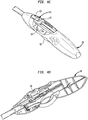
- an exemplary device 10 for gathering of heart valve leaflet tissue includes an elongated catheter assembly 12 adapted to be inserted through the apex of a human heart so that a distal portion 14 of the catheter assembly may reach the patient's mitral valve 1 for repair thereof.
- the catheter assembly 12 includes an outer tube 16, the distal end 17 of which has an open side 19 and a closed side 41.
- An atraumatic tip 11 attached to a sleeve 13a extending proximally from the tip is longitudinally slidable between a deployed condition protruding distally beyond the distal end 17 of the outer tube 16 and a retracted condition.
- the atraumatic tip 11 may include a pair of orthogonally disposed slits 13C that divide the tip into four flaps 13b. As the sleeve 13a is retracted proximally, the flaps 13b may separate from one another, thereby exposing the distal end 17 of the outer tube.
- the outer tube 16 may be made of one or more echogenic materials, so that the outer tube may be more easily visualized inside a patient using three-dimensional echocardiography.
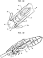
- the catheter assembly 12 further includes tissue support members in the form of substantially closed loops 30a and 30b (collectively, loops 30) that are longitudinally slidable within respective containment tubes 35a and 35b (collectively, containment tubes 35) disposed within the outer tube 16, all of which can be seen in FIGS. 5C and 5D .
- the loops 30 are slidable between an initial position retracted within the containment tubes 35 ( FIG. 2A ) and a tissue-supporting position extending outwardly from the containment tubes ( FIGS. 3A and 3B ).
- the loops 30 may have a substantially linear configuration when fully retracted within the containment tubes 35 and may bend laterally away from the closed side 41 of the outer tube when deployed from the containment tubes.
- the loops 30 may be spaced from one another so as to define a gap 33 between their closed distal ends 32.
- the loops 30 may be formed from a memory metal or a strong, resilient metal or polymer that will cause the loops to automatically bend laterally away from the closed side 41 of the outer tube 16 when deployed.
- a capture tool in the form of a grasping wire 22 may be slideably arranged in a containment tube 20 disposed within the outer tube 16.
- the grasping wire 22 may be longitudinally slidable within the containment tube 20 between a retracted position substantially within the lumen of the containment tube, and a deployed position in which a distal portion of the grasping wire protrudes from the containment tube.
- the containment tube 20 may also be longitudinally slideable between a retracted position within the outer tube and a deployed position in which a distal tip 21 of the containment tube protrudes distally beyond the distal end 17 of the outer tube ( FIGS. 4A and 4B ).
- the grasping wire 22 may have a linear configuration when fully retracted within the containment tube 20, and the distal portion thereof may assume the shape of a hook 24 when deployed from the containment tube.
- the grasping wire 22 may be formed from a memory metal or a strong, resilient metal or polymer that will cause the hook 24 to form automatically when deployed.
- a retaining arm 50 may also be disposed within the outer tube 16 and may be longitudinally slidable therein between an initial or distal position, shown in FIG. 5D , and a retracted or proximal position, shown in FIG. 6A .
- the retaining arm 50 engages a clip 55 disposed adjacent the retaining arm, holding it in place against the closed side of 41 of the outer tube 16. The retraction of the retaining arm 50 releases the clip 55 for application to tissue.
- the clip 55 may be supported in the longitudinal direction L during the sliding movement of the retaining arm 50 by a series of ribs 40 provided on the closed side 41 of the outer tube 16 so as to lie between the closed side and the retaining arm when the retaining arm is in the initial position.
- the ribs 40 may be separated in the longitudinal direction L by a gap 42 sized to receive the clip 55 when the retaining arm is in the initial position.
- the clip 55 may be made of a memory metal and may be biased to curl into a substantially round configuration ( FIG. 7 ) when the retaining arm 50 is retracted proximally and the no longer overlies the clip.
- Each end of the clip 55 may include a prong 56 adapted to become embedded in the leaflet tissue when the clip is deployed.
- a handle 60 may be provided at the proximal end 18 of the outer tube 16 for operating the device 10.
- the handle 60 may include a first button 61, a second button 64, and a third button 66 for controlling the operation of the containment tube 20 and the grasping wire 22, the loops 30, and the retaining arm 50, respectively.
- the first button 61 may have a first portion 62 and a second portion 63 that are moveable longitudinally relative to the handle 60 and relative to one another.
- the first portion 62 may be operatively connected to the containment tube 20, such that sliding movement of the first portion in a proximal or distal direction results in a corresponding sliding movement of the containment tube.
- the second portion 63 may be operatively connected to the grasping wire 22, such that sliding movement of the second portion in a proximal or distal direction results in a corresponding sliding movement of the grasping wire.
- the containment tube 20 and the grasping wire 22 may be moved together by the simultaneous movement of the first and second portions of the button 61.
- the containment tube 20 and the grasping wire 22 may be moved independently of one another by moving one of the portions of the button 61 while the other portion remains stationary. For example, sliding the second portion 63 distally while the first portion 62 remains stationary advances the grasping wire 22 out from the containment tube 20, resulting in deployment of the hook 24.
- the second button 64 may be moveable longitudinally relative to the handle 60 for controlling the movement of the loops 30 relative to the outer tube 16.
- the second button 64 may be operatively connected to one end of a linkage 65, the other end of which may be operatively connected to the loops 30, such that sliding movement of the second button in a proximal or distal direction results in a corresponding sliding movement of the loops.
- the third button 66 may have a trigger shape and may be connected at one end to the handle 60 by a pivot pin 67 that allows for movement of the button in a lateral direction relative to the longitudinal axis of the handle for controlling the movement of the retaining arm 50 relative to the outer tube 16.
- a spring 68 may bias the third button 66 to return to its initial position ( FIG. 2D ) after the button has been actuated ( FIG. 6B ).
- the opposite end 69 of the third button 66 may be pivotally coupled to a linkage assembly including a first linkage 70, a second linkage 71, and a third linkage 72, all of which are pivotally connected to one another in series.
- the third linkage 72 may be connected to the proximal end of the retaining arm 50, such that actuation of the third button 66 may cause the third linkage 72 to slide proximally to retract the retaining arm and thereby deploy the clip 55.
- a safety catch 75 may be connected to the handle 60 by a pivot pin 76, such that the safety catch may rotate between a locked position ( FIGS. 5G and 5H ) that prevents actuation of the third button 66 and an unlocked position ( FIG. 6B ) that frees the third button for actuation.
- a user may first actuate the third button 66 of the handle 60 to retract the retaining arm 50 proximally of the gap 42 between the ribs 40.
- a clip 55 may then be loaded into the gap 42, and the third button 66 may be released.
- the spring 68 will bias the third button 66 back to its initial position, whereupon the retaining arm 50 will slide distally until it covers the clip 55 and holds it in place.
- the distal portion 14 of the catheter assembly 12 may be inserted into the left ventricle of a patient, for example, through the apex of the heart, so that the distal portion extends between the posterior leaflet 2 and the anterior leaflet 3 of the mitral valve 1.
- the distal end 17 of the outer tube 16 may be disposed proximally of the coaption line 5 of the mitral valve 1, with the open side 19 of the outer tube facing the posterior leaflet 2.
- the distal end 17 of the outer tube 16 may be guided to a desired position relative to the coaption line 5 using the assistance of three-dimensional echocardiography to visualize the outer tube or other components of the catheter assembly 12.
- the sleeve 13a of the atraumatic tip 11 may be slid proximally until the flaps 13b are proximal of the open side 19 of the outer tube 16, exposing the inner components of the device 10 for deployment.
- the loops 30 may be deployed by sliding the second button 64 distally from an initial position (shown in FIG. 2C ) to a deployed position (shown in FIG. 4C ).
- the distal movement of the second button 64 moves the loops 30 distally relative to the outer tube 16 and the containment tubes 35.
- the memory of the material forming the loops will cause the ends 32 of the loops to bend laterally away from the closed side 41 of the outer tube 16 and away from one another to expand the internal gap 33 between the loops.
- the outer tube 16 is positioned against or close to the chordae tendineae 8 so that, as the loops 30 are deployed, the ends 32 of the loops will extend along the bottom surface of the posterior leaflet 2 under both the upper portion 6 and the lower portion 7 and between adjacent ones of the chordae tendineae 8.
- the free edge of the posterior leaflet 2 may slide over the loops towards the containment tubes 35, such that tissue of the posterior leaflet overlies the distal end 17 of the outer tube 16.
- the containment tube 20 may be deployed by sliding the first and second portions 62 and 63 of the first button 61 together distally to move the containment tube from an initial position (not shown) to a deployed position (shown in FIG. 4A ).
- the distal movement of the first button 61 moves the tip 21 of the containment tube 20 beyond the distal end 17 of the outer tube 16, such that the tip 21 moves closer to the coaption line 5.
- the hook 24 may then be deployed to an extended position by sliding the second portion 63 of the first button 61 distally relative to the first portion 62 from an initial position (shown in FIG. 2C ) to a deployed position (shown in FIGS. 4C and 4D ).
- the distal movement of the second portion 63 relative to the first portion 62 moves the distal portion of the grasping wire 22 out of the containment tube 20. No longer being constrained by the containment tube 20, the distal portion of the grasping wire 22 may assume the curved shape of the hook 24.
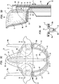
- the hook 24 of the grasping wire 22 may be used to grasp tissue of the posterior leaflet 2 and pull it into the distal end of the outer tube 16. Referring to FIGS. 5A-5F , the hook 24 may be partially retracted against the tissue of the posterior leaflet 2 by sliding the first and second portions 62 and 63 of the first button 61 together proximally. The proximal movement of the first button 61 partially retracts the containment tube 20, and with it the grasping wire 22, such that the hook 24 engages against the upper surface 6 of the posterior leaflet 2 and pulls tissue of the leaflet through the gap 33 between the loops 30a and 30b. As the hook 24 continues to retract proximally between the loops 30a and 30b, captured tissue 15 of the posterior leaflet 2 will be forced between the loops and into the distal end of the outer tube 16.
- a V-shaped pleat 80 will thus be formed in the captured tissue 15.
- the pleat 80 will have a V-shape in longitudinal cross-section, as shown in FIG. 5E , with the lowered center portion of the V underlying the hook 24, and the two upper portions of the V overlying the loops 30a and 30b.
- the pleat 80 will also have a V-shape in transverse cross-section as evident in FIG. 5C , with the lowered center portion of the V extending around the end 25 of the hook 24, and the two upper portions of the V extending from the end of the hook toward the closed side 41 of the outer tube 16.
- the retaining arm 50 may be retracted by releasing the catch 75 and actuating the third button 66 by depressing it toward the handle 60.
- the retaining arm 50 may be retracted until it is proximal of the gap 42 between the ribs 40, as shown in FIG. 6A .
- the retaining arm 50 will no longer overlie the clip 55, such that the two prongs 56 of the clip will be free to spring away from the closed surface 41 of the outer tube 16 and become embedded in the captured tissue 15 of the posterior leaflet 2, thereby securing the tissue in the pleated form.
- the clip 55 may pierce tissue of the posterior leaflet 2 from the bottom surface of the leaflet, thereby retaining the captured tissue 15 in the V-shaped pleat 80.
- the clip 55 may be engaged in the lower portion 7 of the posterior leaflet 2 close to the coaption line 5.
- the two prongs 56 may overlap one another, and the clip 55 may extend along an arc that is greater than 360 degrees.
- a suture may extend between the clip 55 and the catheter assembly 12 so that the clip may be retrieved using the device 10, for example, if the clip has been installed at a sub-optimal location on the posterior leaflet 2 or does not become adequately embedded in the tissue.
- a user may desire to disengage the clip from the tissue and deploy another one.
- the device 10 may be withdrawn from the patient.
- the hook 24 may first be withdrawn from engagement with the posterior leaflet 2 by retracting the second portion 63 of the first button 61 relative to the first portion 62 thereof. This action causes the hook 24 to straighten as the grasping wire 22 retracts into the containment tube 20.
- the loops 30 may be withdrawn from engagement with the posterior leaflet 2 by moving the second button 64 proximally, thereby retracting the loops into the containment tubes 35. As the loops 30 retract, the ends 32 of the loops will move out from under the posterior leaflet 2.
- the posterior leaflet may assume its natural orientation, such as that shown in FIG. 8 .
- the clip may have an installed orientation that is different than that shown in FIG. 7 , such that the prongs 56 may point toward the anterior leaflet 3, while the center of the clip faces away from the anterior leaflet.
- catheter assembly 12 may be withdrawn from the patient through the apex of the heart. The procedure described above may be repeated to apply one or more additional clips 55 onto the same posterior leaflet 2.
- catheter assembly 12 is described as being controllable by the movement of a particular configuration of buttons 61, 64, and 66 of the handle 60, any mechanisms that are adapted to control the movement and deployment of the containment tube 20, grasping wire 22, loops 30, and clip 55 may be used.
- the capture tool is shown as a single grasping wire 22 having a single hook 24 that cooperates with support members shown in the form of two loops 30 to capture leaflet tissue and form same into a V-shaped pleat 80
- the capture tool and support members may have any shape or configuration that may be adapted to cooperate to grasp a target portion of valve leaflet tissue and to capture such tissue, forming any number of pleats therein, such that a clip may be applied to the captured tissue.
- a support member having a single loop may cooperate with two hooks that are laterally spaced apart from one another to form leaflet tissue into a pleat, or a single hook may cooperate with a single loop, the sides of which are spaced apart sufficiently to form leaflet tissue into a pleat therebetween.
- the invention contemplates support members having any number of hooks cooperating with any number of loops to form any number of pleats in the captured tissue. It will be appreciated that the more pleats that are formed, the more the tissue of the valve leaflet can be tightened.
- the capture tool has been described as a grasping wire 22, it may take other forms, including for example, a pincer-like structure such as a clamp, or any other structure that can guide leaflet tissue into a fold or pleat onto which a clip can be attached.
- the support members may have other configurations, such as the solid tines of a fork, an arm having a curved surface such that outer edges of the arm can serve as loops, a lattice structure, or any other structure capable of supporting the leaflet tissue against the force exerted by retraction of the hook.
- the catheter assembly 12 has been described as including ribs 40 on the closed side 41 of the outer tube 16 for holding the clip 55 in place, that need not be the case. Rather, a recess may be formed in the closed side 41 of the outer tube 16 for receiving the clip.
- the retaining arm 50 has been described as engaging the clip 55 when the retaining arm is in the distal position and releasing the clip when the retaining arm is in the proximal position, the invention contemplates an alternative retaining arm that retains the clip when the retaining arm is in a proximal position and releases the clip when the retaining arm is moved to a distal position.
- loops 30 have been described as being made from a memory metal so that the closed ends 32 of the loops automatically bend laterally away from the closed side 41 of the outer tube 16 when the loops are extended distally from the outer tube
- other mechanisms may be used for controlling such lateral movement of the ends of the loops.
- support members such as the loops 30 or support members having other structures may be made of a non-memory material, and cam surfaces within the outer tube 16 may guide the support members as they are deployed and retracted.
- a mechanism controlled by a dedicated button of the handle may be used to actuate lateral movement of the closed ends 32 of the loops 30 relative to the outer tube 16.
- the invention contemplates devices that are adapted to apply a plurality of clips to the leaflet tissue during a single insertion of the device into a patient.
- the gap 42 between the ribs 40 may be sufficiently large to accommodate a plurality of clips 55 in side-by-side relationship in the longitudinal direction of the outer tube 16, or a series of ribs 40 may be formed along the length of the outer tube 16, with a gap 42 sized to receive an individual clip being defined between each adjacent pair of ribs.
- the retaining arm 50 may be retracted to a first position to apply a first clip 55 to the tissue at a first target location and may then be further retracted to a second position to apply a second clip 55 to the tissue at a second target location spaced from the first location.
- the various delivery devices have been described herein in connection with tightening the posterior leaflet of a mitral valve, all of the delivery devices may be used on other heart valve leaflets, such as the anterior leaflet of the mitral valve, or on any other tissue of the body for which a reduction in the length of the tissue would be beneficial.
- the invention herein has been described with reference to particular embodiments in which the catheter assembly is inserted into the patient through the apex of the heart (i.e., transapical insertion), it is to be understood that the invention contemplates embodiments in which the catheter assembly extends through another portion of the heart, through a portion of the vasculature of the patient to reach the heart, for example, through a transfemoral or subclavian artery, or through the aorta. In such embodiments, some of the device components may have to be oriented in a different direction to that described herein. For example, the invention contemplates embodiments in which the distal portion of the catheter assembly approaches the mitral valve from the upstream side as well as from the downstream side of the valve.
- the present invention enjoys wide industrial applicability including, but not limited to, methods and devices for gathering tissue in a patient.
Landscapes
- Health & Medical Sciences (AREA)
- Life Sciences & Earth Sciences (AREA)
- Surgery (AREA)
- General Health & Medical Sciences (AREA)
- Public Health (AREA)
- Biomedical Technology (AREA)
- Heart & Thoracic Surgery (AREA)
- Veterinary Medicine (AREA)
- Engineering & Computer Science (AREA)
- Animal Behavior & Ethology (AREA)
- Molecular Biology (AREA)
- Nuclear Medicine, Radiotherapy & Molecular Imaging (AREA)
- Medical Informatics (AREA)
- Vascular Medicine (AREA)
- Cardiology (AREA)
- Reproductive Health (AREA)
- Oral & Maxillofacial Surgery (AREA)
- Transplantation (AREA)
- Surgical Instruments (AREA)
- Prostheses (AREA)
Claims (15)
- Vorrichtung (10) zum Aufnehmen von Gewebe von einem Herzklappensegel, wobei die Vorrichtung umfasst:ein längliches Rohr (16);ein Gewebestützelement, das relativ zu dem Rohr zwischen einer eingefahrenen Position und einer ausgefahrenen Position bewegt werden kann, wobei das Gewebestützelement mindestens zwei voneinander beabstandete Stützelemente (30) hat; undein Ergreifungswerkzeug, das relativ zu dem Rohr und zwischen den Stützelementen zwischen einer eingefahrenen und einer ausgefahrenen Position bewegt werden kann,wobei das Ergreifungswerkzeug und das Gewebestützelement betriebsbereit sind, um Gewebe von dem Herzklappensegel dazwischen zu ergreifen, so dass das ergriffene Gewebe eine aufgenommene Konfiguration hat,dadurch gekennzeichnet, dassdas Ergreifungswerkzeug einen Greifdraht (22) umfasst, der verschiebbar in einem Einhausungsrohr (20) angeordnet ist, und wobei ein distaler Abschnitt von dem Greifdraht dazu angepasst ist, sich von einer linearen Form in eine Hakenform (24) zu verändern, wenn der distale Abschnitt von dem Greifdraht aus dem Einhausungsrohr ausgefahren wird.
- Vorrichtung nach Anspruch 1, wobei die Stützelemente aus einem Memory-Metall hergestellt sind.
- Vorrichtung nach Anspruch 1, wobei sich das längliche Rohr in eine Längsrichtung erstreckt und distale Enden von den Stützelementen dazu angepasst sind, sich seitlich von dem Ergreifungswerkzeug in einer Richtung quer zu der Längsrichtung weg zu bewegen, wenn sich die Stützelemente von der eingefahrenen Position in die ausgefahrene Position bewegen.
- Vorrichtung nach Anspruch 1, weiter einen Betätigungsgriff (60) mit einem Betätigungselement umfassend, das dazu angepasst ist, eine Bewegung von dem Gewebestützelement zwischen den eingefahrenen und ausgefahrenen Positionen zu steuern.
- Vorrichtung nach Anspruch 1, wobei jedes Stützelement eine Schleife (30a; 30b) mit einem distalen Ende (32) umfasst, wobei die distalen Enden von den Schleifen voneinander durch eine Lücke (33) beabstandet sind.
- Vorrichtung nach Anspruch 1, wobei ein distales Ende von dem Ergreifungswerkzeug in der ausgefahrenen Position eine Hakenform hat.
- Vorrichtung nach Anspruch 1, wobei der Greifdraht aus einem Memory-Metall hergestellt ist.
- Vorrichtung nach Anspruch 1, weiter einen Betätigungsgriff (60) mit einem Betätigungselement umfassend, das dazu angepasst ist, eine Bewegung von dem Greifdraht zwischen eingefahrenen und ausgefahrenen Positionen und eine Bewegung von dem Einhausungsrohr zwischen eingefahrenen und ausgefahrenen Positionen zu steuern.
- Vorrichtung nach Anspruch 8, wobei eine Betätigung von dem Betätigungselement eine gleichzeitige Bewegung von dem Greifdraht und dem Einhausungsrohr steuert.
- Vorrichtung nach Anspruch 8, wobei das Betätigungselement erste und zweite Abschnitte hat, die relativ zueinander beweglich sind, wobei der erste Abschnitt dazu angepasst ist, eine Bewegung von dem Greifdraht zu steuern, und der zweite Abschnitt dazu angepasst ist, eine Bewegung von dem Einhausungsrohr zu steuern.
- Vorrichtung nach Anspruch 10, wobei der erste Abschnitt dazu angepasst ist, eine Bewegung von dem Greifdraht unabhängig von einer Bewegung von dem Einhausungsrohr zu steuern.
- Vorrichtung nach Anspruch 1, weiter eine lösbare Klammer (55) umfassend, die dazu angepasst ist, an dem Gewebe zum Halten des Gewebes in der aufgenommenen Position angebracht zu werden.
- Vorrichtung nach Anspruch 12, weiter einen Haltearm (50) umfassend, der zwischen einer ersten Position zum Halten der Klammern und einer zweiten Position zum Lösen der Klammer für eine Anbringung an dem Gewebe bewegt werden kann.
- Vorrichtung nach Anspruch 13, wobei die Klammern von einem offenen Zustand in einen Klemmzustand gespannt ist, wobei der Haltearm in der ersten Position die Klammer in der offenen Konfiguration hält und der Haltearm in der zweiten Position die Klammer für eine Anbringung an dem Gewebe löst.
- Vorrichtung nach Anspruch 13, weiter einen Betätigungsgriff (60) mit einem Betätigungselement umfassend, das dazu angepasst ist, eine Bewegung von dem Haltearm zwischen der ersten Position und der zweiten Position zu steuern.
Applications Claiming Priority (2)
| Application Number | Priority Date | Filing Date | Title |
|---|---|---|---|
| US201261594122P | 2012-02-02 | 2012-02-02 | |
| PCT/US2013/024304 WO2013116617A1 (en) | 2012-02-02 | 2013-02-01 | Apparatus and method for heart valve repair |
Publications (2)
| Publication Number | Publication Date |
|---|---|
| EP2809270A1 EP2809270A1 (de) | 2014-12-10 |
| EP2809270B1 true EP2809270B1 (de) | 2017-05-31 |
Family
ID=47684074
Family Applications (1)
| Application Number | Title | Priority Date | Filing Date |
|---|---|---|---|
| EP13703712.3A Not-in-force EP2809270B1 (de) | 2012-02-02 | 2013-02-01 | Vorrichtung zur reparatur einer herzklappe |
Country Status (4)
| Country | Link |
|---|---|
| US (1) | US10058348B2 (de) |
| EP (1) | EP2809270B1 (de) |
| ES (1) | ES2631652T3 (de) |
| WO (1) | WO2013116617A1 (de) |
Cited By (15)
| Publication number | Priority date | Publication date | Assignee | Title |
|---|---|---|---|---|
| US10856984B2 (en) | 2017-08-25 | 2020-12-08 | Neovasc Tiara Inc. | Sequentially deployed transcatheter mitral valve prosthesis |
| US11311376B2 (en) | 2019-06-20 | 2022-04-26 | Neovase Tiara Inc. | Low profile prosthetic mitral valve |
| US11357622B2 (en) | 2016-01-29 | 2022-06-14 | Neovase Tiara Inc. | Prosthetic valve for avoiding obstruction of outflow |
| US11389294B2 (en) | 2012-05-30 | 2022-07-19 | Neovasc Tiara Inc. | Methods and apparatus for loading a prosthesis onto a delivery system |
| US11389291B2 (en) | 2013-04-04 | 2022-07-19 | Neovase Tiara Inc. | Methods and apparatus for delivering a prosthetic valve to a beating heart |
| US11413139B2 (en) | 2011-11-23 | 2022-08-16 | Neovasc Tiara Inc. | Sequentially deployed transcatheter mitral valve prosthesis |
| US11419720B2 (en) | 2010-05-05 | 2022-08-23 | Neovasc Tiara Inc. | Transcatheter mitral valve prosthesis |
| US11464631B2 (en) | 2016-11-21 | 2022-10-11 | Neovasc Tiara Inc. | Methods and systems for rapid retraction of a transcatheter heart valve delivery system |
| US11491006B2 (en) | 2019-04-10 | 2022-11-08 | Neovasc Tiara Inc. | Prosthetic valve with natural blood flow |
| US11497602B2 (en) | 2012-02-14 | 2022-11-15 | Neovasc Tiara Inc. | Methods and apparatus for engaging a valve prosthesis with tissue |
| US11602429B2 (en) | 2019-04-01 | 2023-03-14 | Neovasc Tiara Inc. | Controllably deployable prosthetic valve |
| US11737872B2 (en) | 2018-11-08 | 2023-08-29 | Neovasc Tiara Inc. | Ventricular deployment of a transcatheter mitral valve prosthesis |
| US11779742B2 (en) | 2019-05-20 | 2023-10-10 | Neovasc Tiara Inc. | Introducer with hemostasis mechanism |
| US11998447B2 (en) | 2019-03-08 | 2024-06-04 | Neovasc Tiara Inc. | Retrievable prosthesis delivery system |
| US12109111B2 (en) | 2015-12-15 | 2024-10-08 | Neovasc Tiara Inc. | Transseptal delivery system |
Families Citing this family (21)
| Publication number | Priority date | Publication date | Assignee | Title |
|---|---|---|---|---|
| EP2670313B1 (de) | 2011-02-01 | 2016-01-20 | St. Jude Medical, Inc. | Vorrichtung zur reparatur einer herzklappe |
| US9610082B2 (en) | 2012-01-25 | 2017-04-04 | St. Jude Medical, Inc. | Apparatus and method for heart valve repair |
| US9883855B2 (en) | 2012-01-25 | 2018-02-06 | St. Jude Medical, Llc | Apparatus and method for heart valve repair |
| US10058348B2 (en) | 2012-02-02 | 2018-08-28 | St. Jude Medical, Cardiology Division, Inc. | Apparatus and method for heart valve repair |
| US9254141B2 (en) | 2012-08-02 | 2016-02-09 | St. Jude Medical, Inc. | Apparatus and method for heart valve repair |
| US10105219B2 (en) | 2012-08-02 | 2018-10-23 | St. Jude Medical, Cardiology Division, Inc. | Mitral valve leaflet clip |
| US9125653B2 (en) | 2012-08-02 | 2015-09-08 | St. Jude Medical, Cardiology Division, Inc. | Flexible nosecone for percutaneous device |
| US9662205B2 (en) | 2012-08-02 | 2017-05-30 | St. Jude Medical, Cardiology Division, Inc. | Apparatus and method for heart valve repair |
| US9066710B2 (en) | 2012-10-19 | 2015-06-30 | St. Jude Medical, Cardiology Division, Inc. | Apparatus and method for heart valve repair |
| US9642706B2 (en) | 2013-03-11 | 2017-05-09 | St. Jude Medical, Llc | Apparatus and method for heart valve repair |
| EP2870933B1 (de) * | 2013-11-12 | 2017-07-19 | St. Jude Medical, Cardiology Division, Inc. | Transfemoral-Mitralklappenreparaturabgabevorrichtung |
| US9839765B2 (en) | 2013-11-12 | 2017-12-12 | St. Jude Medical, Cardiology Division, Inc. | Transfemoral mitral valve repair delivery device |
| US10779944B2 (en) | 2015-01-05 | 2020-09-22 | Strait Access Technologies Holdings (Pty) Ltd | Heart valve leaflet capture device |
| US12402885B2 (en) | 2017-09-23 | 2025-09-02 | Universität Zürich | Medical occlusion device |
| EP3459469A1 (de) | 2017-09-23 | 2019-03-27 | Universität Zürich | Medizinische okklusionsvorrichtung |
| CN107822743A (zh) | 2017-10-20 | 2018-03-23 | 北京迈迪顶峰医疗科技有限公司 | 一种用于微创手术进行瓣叶修复的系统 |
| WO2019136378A1 (en) * | 2018-01-05 | 2019-07-11 | Mitrx, Inc. | Pursestring suture retractor and method of use |
| US11026791B2 (en) | 2018-03-20 | 2021-06-08 | Medtronic Vascular, Inc. | Flexible canopy valve repair systems and methods of use |
| US11285003B2 (en) | 2018-03-20 | 2022-03-29 | Medtronic Vascular, Inc. | Prolapse prevention device and methods of use thereof |
| EP4033999B1 (de) | 2019-09-26 | 2024-11-27 | Universität Zürich | Verschlussvorrichtungen für das linke herzohr |
| WO2021191833A1 (en) | 2020-03-25 | 2021-09-30 | Universitat Zurich | Medical occluder delivery systems |
Family Cites Families (99)
| Publication number | Priority date | Publication date | Assignee | Title |
|---|---|---|---|---|
| US6120437A (en) | 1988-07-22 | 2000-09-19 | Inbae Yoon | Methods for creating spaces at obstructed sites endoscopically and methods therefor |
| US5749879A (en) | 1989-08-16 | 1998-05-12 | Medtronic, Inc. | Device or apparatus for manipulating matter |
| US5041129A (en) | 1990-07-02 | 1991-08-20 | Acufex Microsurgical, Inc. | Slotted suture anchor and method of anchoring a suture |
| DE4024106C1 (de) | 1990-07-30 | 1992-04-23 | Ethicon Gmbh & Co Kg, 2000 Norderstedt, De | |
| US5098440A (en) * | 1990-08-14 | 1992-03-24 | Cordis Corporation | Object retrieval method and apparatus |
| CA2143560C (en) | 1994-03-02 | 2007-01-16 | Mark Fogelberg | Sterile occlusion fasteners and instrument and method for their placement |
| US5573542A (en) | 1994-08-17 | 1996-11-12 | Tahoe Surgical Instruments-Puerto Rico | Endoscopic suture placement tool |
| US5499991A (en) | 1994-12-19 | 1996-03-19 | Linvatec Corporation | Endoscopic needle with suture retriever |
| US5626607A (en) | 1995-04-03 | 1997-05-06 | Heartport, Inc. | Clamp assembly and method of use |
| US5894843A (en) | 1996-02-20 | 1999-04-20 | Cardiothoracic Systems, Inc. | Surgical method for stabilizing the beating heart during coronary artery bypass graft surgery |
| WO1997038634A1 (en) | 1996-04-18 | 1997-10-23 | Applied Medical Resources Corporation | Malleable clip applier and method |
| US5921993A (en) | 1997-05-01 | 1999-07-13 | Yoon; Inbae | Methods of endoscopic tubal ligation |
| ES2335252T3 (es) | 1997-06-27 | 2010-03-23 | The Trustees Of Columbia University In The City Of New York | Aparato para la reparacion de valvulas del sistema circulatorio. |
| AU2002300522B2 (en) | 1997-06-27 | 2007-01-25 | The Trustees Of Columbia University In The City Of New York | Method and Apparatus for Circulatory Valve Repair |
| FR2768324B1 (fr) * | 1997-09-12 | 1999-12-10 | Jacques Seguin | Instrument chirurgical permettant, par voie percutanee, de fixer l'une a l'autre deux zones de tissu mou, normalement mutuellement distantes |
| US20040087985A1 (en) | 1999-03-19 | 2004-05-06 | Amir Loshakove | Graft and connector delivery |
| US7569062B1 (en) | 1998-07-15 | 2009-08-04 | St. Jude Medical, Inc. | Mitral and tricuspid valve repair |
| US6352503B1 (en) * | 1998-07-17 | 2002-03-05 | Olympus Optical Co., Ltd. | Endoscopic surgery apparatus |
| US6093173A (en) | 1998-09-09 | 2000-07-25 | Embol-X, Inc. | Introducer/dilator with balloon protection and methods of use |
| WO2000045691A2 (en) * | 1999-02-04 | 2000-08-10 | Da Silva Branco Antonio Carlos | Kit for endovascular venous surgery |
| US6752813B2 (en) | 1999-04-09 | 2004-06-22 | Evalve, Inc. | Methods and devices for capturing and fixing leaflets in valve repair |
| DE60045429D1 (de) | 1999-04-09 | 2011-02-03 | Evalve Inc | Vorrichtung zur Herzklappenoperation |
| US7811296B2 (en) | 1999-04-09 | 2010-10-12 | Evalve, Inc. | Fixation devices for variation in engagement of tissue |
| US6488689B1 (en) | 1999-05-20 | 2002-12-03 | Aaron V. Kaplan | Methods and apparatus for transpericardial left atrial appendage closure |
| US6626930B1 (en) | 1999-10-21 | 2003-09-30 | Edwards Lifesciences Corporation | Minimally invasive mitral valve repair method and apparatus |
| US6428548B1 (en) | 1999-11-18 | 2002-08-06 | Russell F. Durgin | Apparatus and method for compressing body tissue |
| US6602263B1 (en) | 1999-11-30 | 2003-08-05 | St. Jude Medical Atg, Inc. | Medical grafting methods and apparatus |
| CA2407373C (en) | 2000-05-02 | 2008-11-25 | Boris Reydel | Introducer device for catheters o.t.l. with eversible sleeve |
| US6547798B1 (en) | 2000-05-04 | 2003-04-15 | Inbae Yoon | Ring applicator and method for applying elastic rings to anatomical tissue structures |
| DE10031436A1 (de) | 2000-06-28 | 2002-01-10 | Alexander Von Fuchs | Gleitschutz für einen Gehäusekopf medizinischer Instrumente |
| US6440152B1 (en) | 2000-07-28 | 2002-08-27 | Microvena Corporation | Defect occluder release assembly and method |
| EP1179322A3 (de) | 2000-08-09 | 2004-02-25 | BIOTRONIK Mess- und Therapiegeräte GmbH & Co Ingenieurbüro Berlin | Verfahren und Vorrichtung zum Crimpen eines Stents |
| SE0002878D0 (sv) | 2000-08-11 | 2000-08-11 | Kimblad Ola | Device and method for treatment of atrioventricular regurgitation |
| US20020107531A1 (en) | 2001-02-06 | 2002-08-08 | Schreck Stefan G. | Method and system for tissue repair using dual catheters |
| US20050125011A1 (en) | 2001-04-24 | 2005-06-09 | Spence Paul A. | Tissue fastening systems and methods utilizing magnetic guidance |
| US6558400B2 (en) | 2001-05-30 | 2003-05-06 | Satiety, Inc. | Obesity treatment tools and methods |
| US6679892B2 (en) | 2001-09-28 | 2004-01-20 | Ethicon, Inc. | Surgical device for ligating and severing vessels |
| US6575971B2 (en) | 2001-11-15 | 2003-06-10 | Quantum Cor, Inc. | Cardiac valve leaflet stapler device and methods thereof |
| US7357806B2 (en) | 2001-12-06 | 2008-04-15 | Ethicon Endo-Surgery, Inc. | Clip ejector for endoscopic clip applier |
| US6978176B2 (en) | 2001-12-08 | 2005-12-20 | Lattouf Omar M | Treatment for patient with congestive heart failure |
| WO2003096881A2 (en) | 2002-05-14 | 2003-11-27 | University Of Pittsburgh | Device and method of use for functional isolation of animal or human tissues |
| US20060122633A1 (en) | 2002-06-13 | 2006-06-08 | John To | Methods and devices for termination |
| JP4109030B2 (ja) | 2002-07-19 | 2008-06-25 | オリンパス株式会社 | 生体組織のクリップ装置 |
| US6945978B1 (en) * | 2002-11-15 | 2005-09-20 | Advanced Cardiovascular Systems, Inc. | Heart valve catheter |
| US8398656B2 (en) | 2003-01-30 | 2013-03-19 | Integrated Vascular Systems, Inc. | Clip applier and methods of use |
| US7381210B2 (en) | 2003-03-14 | 2008-06-03 | Edwards Lifesciences Corporation | Mitral valve repair system and method for use |
| US7105000B2 (en) | 2003-03-25 | 2006-09-12 | Ethicon Endo-Surgery, Inc. | Surgical jaw assembly with increased mechanical advantage |
| US20050107871A1 (en) | 2003-03-30 | 2005-05-19 | Fidel Realyvasquez | Apparatus and methods for valve repair |
| US8372112B2 (en) | 2003-04-11 | 2013-02-12 | St. Jude Medical, Cardiology Division, Inc. | Closure devices, related delivery methods, and related methods of use |
| US20050096671A1 (en) | 2003-10-31 | 2005-05-05 | Parris Wellman | Control mechanism for a surgical instrument |
| US20050251189A1 (en) | 2004-05-07 | 2005-11-10 | Usgi Medical Inc. | Multi-position tissue manipulation assembly |
| US7618427B2 (en) | 2003-12-29 | 2009-11-17 | Ethicon Endo-Surgery, Inc. | Device and method for intralumenal anastomosis |
| US20050149072A1 (en) | 2003-12-31 | 2005-07-07 | Devries Robert B. | Devices and methods for tissue invagination |
| US20050177176A1 (en) | 2004-02-05 | 2005-08-11 | Craig Gerbi | Single-fold system for tissue approximation and fixation |
| US20050250985A1 (en) * | 2004-05-07 | 2005-11-10 | Usgi Medical Inc. | Self-locking removable apparatus and methods for manipulating and securing tissue |
| CA2748617C (en) | 2004-09-27 | 2014-09-23 | Evalve, Inc. | Methods and devices for tissue grasping and assessment |
| EP3653134B1 (de) | 2004-09-29 | 2021-04-28 | USGI Medical Inc | Vorrichtung zur manipulation und sicherung von gewebe |
| DE102005004622A1 (de) | 2005-02-01 | 2006-08-10 | Stm Medizintechnik Starnberg Gmbh | Endoskop mit längsgeführtem Stülpschlauch |
| US8157815B2 (en) | 2005-05-20 | 2012-04-17 | Neotract, Inc. | Integrated handle assembly for anchor delivery system |
| US8951285B2 (en) | 2005-07-05 | 2015-02-10 | Mitralign, Inc. | Tissue anchor, anchoring system and methods of using the same |
| US20070049952A1 (en) | 2005-08-30 | 2007-03-01 | Weiss Steven J | Apparatus and method for mitral valve repair without cardiopulmonary bypass, including transmural techniques |
| EP1945110A2 (de) | 2005-10-26 | 2008-07-23 | The Brigham and Women's Hospital, Inc. | Vorrichtung und verfahren zur behandlung einer mitralklappenregurgitation |
| US7328828B2 (en) | 2005-11-04 | 2008-02-12 | Ethicon Endo-Surgery, Inc, | Lockout mechanisms and surgical instruments including same |
| US7673780B2 (en) | 2005-11-09 | 2010-03-09 | Ethicon Endo-Surgery, Inc. | Articulation joint with improved moment arm extension for articulating an end effector of a surgical instrument |
| US20070198032A1 (en) | 2006-02-22 | 2007-08-23 | Ethicon Endo-Surgery, Inc. | Methods and devices for fastener removal |
| US20070225734A1 (en) | 2006-03-22 | 2007-09-27 | Minos Medical | Systems and methods for less invasive resolution of maladies of tissue including the appendix, gall bladder, and hemorrhoids |
| GB2437921B (en) * | 2006-05-10 | 2011-08-03 | Francis Wells | Heart valve repair |
| US8740962B2 (en) * | 2006-11-07 | 2014-06-03 | Dc Devices, Inc. | Prosthesis for retrieval and deployment |
| US20080125796A1 (en) | 2006-11-28 | 2008-05-29 | Stryker Development Llc | Gastrotomy closure device |
| JP2010511469A (ja) | 2006-12-05 | 2010-04-15 | バルテック カーディオ,リミティド | セグメント化リング配置 |
| JP5297816B2 (ja) | 2007-01-26 | 2013-09-25 | オリンパスメディカルシステムズ株式会社 | 把持装置 |
| US8979872B2 (en) | 2007-03-13 | 2015-03-17 | Longevity Surgical, Inc. | Devices for engaging, approximating and fastening tissue |
| US8852216B2 (en) | 2007-03-23 | 2014-10-07 | Ethicon Endo-Surgery, Inc. | Tissue approximation methods |
| US8246636B2 (en) | 2007-03-29 | 2012-08-21 | Nobles Medical Technologies, Inc. | Suturing devices and methods for closing a patent foramen ovale |
| US20080294175A1 (en) | 2007-05-21 | 2008-11-27 | Epitek, Inc. | Left atrial appendage closure |
| US20080300624A1 (en) | 2007-05-30 | 2008-12-04 | Ethicon Endo-Surgery, Inc. | Tissue Stabilizer and Fastener |
| WO2009032695A1 (en) | 2007-08-29 | 2009-03-12 | Trinity Orthopedics, Llc | Annulus fibrosus repair device and methods |
| US8512362B2 (en) | 2007-11-05 | 2013-08-20 | Usgi Medical Inc. | Endoscopic ligation |
| EP2231001A2 (de) | 2008-01-07 | 2010-09-29 | Odem Medical Ltd. | Verfahren und vorrichtung für behandlungen im perikardraum |
| US8968393B2 (en) * | 2008-02-28 | 2015-03-03 | Medtronic, Inc. | System and method for percutaneous mitral valve repair |
| GB0818101D0 (en) | 2008-10-03 | 2008-11-05 | Femcare Nikomed Ltd | Applicator for surgical clips |
| FR2942390B1 (fr) | 2009-02-20 | 2011-05-20 | Assistance Publique Hopitaux Paris | Dispositif pour effectuer une intervention endoscopique en utilisant un outil d'intervention endoscopique et procede d'utilisation. |
| US20110054496A1 (en) | 2009-08-27 | 2011-03-03 | Md-Art, Inc. | Vascular clip |
| ES2524544T3 (es) | 2009-09-25 | 2014-12-10 | Boston Scientific Scimed, Inc. | Dispositivos para aproximar tejido |
| US8734469B2 (en) | 2009-10-13 | 2014-05-27 | Covidien Lp | Suture clip applier |
| US20110093009A1 (en) * | 2009-10-16 | 2011-04-21 | Ethicon Endo-Surgery, Inc. | Otomy closure device |
| WO2011053673A1 (en) | 2009-10-30 | 2011-05-05 | Wilson-Cook Medical Inc. | Apparatus and methods for achieving serosa-to-serosa closure of a bodily opening |
| US8353438B2 (en) | 2009-11-19 | 2013-01-15 | Ethicon Endo-Surgery, Inc. | Circular stapler introducer with rigid cap assembly configured for easy removal |
| EP2528517B1 (de) * | 2010-01-27 | 2018-04-18 | Merit Medical Systems, Inc. | Formbare abrufvorrichtung |
| US8795269B2 (en) | 2010-07-26 | 2014-08-05 | Covidien Lp | Rotary tissue sealer and divider |
| US9451967B2 (en) | 2010-11-01 | 2016-09-27 | Boston Scientific Scimed, Inc. | Tissue closure |
| US20120165842A1 (en) | 2010-12-22 | 2012-06-28 | Ethicon Endo-Surgery, Inc. | Endoluminal fold creation |
| EP2670313B1 (de) | 2011-02-01 | 2016-01-20 | St. Jude Medical, Inc. | Vorrichtung zur reparatur einer herzklappe |
| WO2012122006A2 (en) | 2011-03-04 | 2012-09-13 | Jenkins Clinic, Inc. | Surgical ligation clip and applicator device |
| EP2736452A1 (de) | 2011-07-29 | 2014-06-04 | St. Jude Medical, Inc. | Klammer zur reparatur von herzklappen |
| US8784442B2 (en) | 2011-08-19 | 2014-07-22 | Empirilon Technology, Llc | Methods and systems for performing thrombectomy procedures |
| US10058348B2 (en) | 2012-02-02 | 2018-08-28 | St. Jude Medical, Cardiology Division, Inc. | Apparatus and method for heart valve repair |
| US9662205B2 (en) | 2012-08-02 | 2017-05-30 | St. Jude Medical, Cardiology Division, Inc. | Apparatus and method for heart valve repair |
| US10105219B2 (en) | 2012-08-02 | 2018-10-23 | St. Jude Medical, Cardiology Division, Inc. | Mitral valve leaflet clip |
-
2013
- 2013-02-01 US US14/375,986 patent/US10058348B2/en not_active Expired - Fee Related
- 2013-02-01 WO PCT/US2013/024304 patent/WO2013116617A1/en not_active Ceased
- 2013-02-01 EP EP13703712.3A patent/EP2809270B1/de not_active Not-in-force
- 2013-02-01 ES ES13703712.3T patent/ES2631652T3/es active Active
Cited By (22)
| Publication number | Priority date | Publication date | Assignee | Title |
|---|---|---|---|---|
| US11419720B2 (en) | 2010-05-05 | 2022-08-23 | Neovasc Tiara Inc. | Transcatheter mitral valve prosthesis |
| US11413139B2 (en) | 2011-11-23 | 2022-08-16 | Neovasc Tiara Inc. | Sequentially deployed transcatheter mitral valve prosthesis |
| US12053369B2 (en) | 2011-11-23 | 2024-08-06 | Neovasc Tiara Inc. | Sequentially deployed transcatheter mitral valve prosthesis |
| US11497602B2 (en) | 2012-02-14 | 2022-11-15 | Neovasc Tiara Inc. | Methods and apparatus for engaging a valve prosthesis with tissue |
| US12138159B2 (en) | 2012-02-14 | 2024-11-12 | Neovasc Tiara Inc. | Methods and apparatus for engaging a valve prosthesis with tissue |
| US11389294B2 (en) | 2012-05-30 | 2022-07-19 | Neovasc Tiara Inc. | Methods and apparatus for loading a prosthesis onto a delivery system |
| US11617650B2 (en) | 2012-05-30 | 2023-04-04 | Neovasc Tiara Inc. | Methods and apparatus for loading a prosthesis onto a delivery system |
| US11389291B2 (en) | 2013-04-04 | 2022-07-19 | Neovase Tiara Inc. | Methods and apparatus for delivering a prosthetic valve to a beating heart |
| US12109111B2 (en) | 2015-12-15 | 2024-10-08 | Neovasc Tiara Inc. | Transseptal delivery system |
| US12193932B2 (en) | 2016-01-29 | 2025-01-14 | Neovasc Tiara Inc. | Prosthetic valve for avoiding obstruction of outflow |
| US11357622B2 (en) | 2016-01-29 | 2022-06-14 | Neovase Tiara Inc. | Prosthetic valve for avoiding obstruction of outflow |
| US11464631B2 (en) | 2016-11-21 | 2022-10-11 | Neovasc Tiara Inc. | Methods and systems for rapid retraction of a transcatheter heart valve delivery system |
| US12201524B2 (en) | 2016-11-21 | 2025-01-21 | Neovasc Tiara Inc. | Methods and systems for rapid retraction of a transcatheter heart valve delivery system |
| US10856984B2 (en) | 2017-08-25 | 2020-12-08 | Neovasc Tiara Inc. | Sequentially deployed transcatheter mitral valve prosthesis |
| US11793640B2 (en) | 2017-08-25 | 2023-10-24 | Neovasc Tiara Inc. | Sequentially deployed transcatheter mitral valve prosthesis |
| US11737872B2 (en) | 2018-11-08 | 2023-08-29 | Neovasc Tiara Inc. | Ventricular deployment of a transcatheter mitral valve prosthesis |
| US11998447B2 (en) | 2019-03-08 | 2024-06-04 | Neovasc Tiara Inc. | Retrievable prosthesis delivery system |
| US11602429B2 (en) | 2019-04-01 | 2023-03-14 | Neovasc Tiara Inc. | Controllably deployable prosthetic valve |
| US11491006B2 (en) | 2019-04-10 | 2022-11-08 | Neovasc Tiara Inc. | Prosthetic valve with natural blood flow |
| US11779742B2 (en) | 2019-05-20 | 2023-10-10 | Neovasc Tiara Inc. | Introducer with hemostasis mechanism |
| US11931254B2 (en) | 2019-06-20 | 2024-03-19 | Neovasc Tiara Inc. | Low profile prosthetic mitral valve |
| US11311376B2 (en) | 2019-06-20 | 2022-04-26 | Neovase Tiara Inc. | Low profile prosthetic mitral valve |
Also Published As
| Publication number | Publication date |
|---|---|
| EP2809270A1 (de) | 2014-12-10 |
| ES2631652T3 (es) | 2017-09-01 |
| US10058348B2 (en) | 2018-08-28 |
| US20140379002A1 (en) | 2014-12-25 |
| WO2013116617A1 (en) | 2013-08-08 |
Similar Documents
| Publication | Publication Date | Title |
|---|---|---|
| EP2809270B1 (de) | Vorrichtung zur reparatur einer herzklappe | |
| EP2879589B1 (de) | Vorrichtung zur reparatur einer herzklappe | |
| US9498228B2 (en) | Apparatus and method for heart valve repair | |
| US9066710B2 (en) | Apparatus and method for heart valve repair | |
| EP2806805B1 (de) | Vorrichtung zur reparatur einer herzklappe | |
| US10617521B2 (en) | Apparatus and method for heart valve repair | |
| US9999425B2 (en) | Mitral valve leaflet clip | |
| US9125653B2 (en) | Flexible nosecone for percutaneous device | |
| US10034667B2 (en) | Apparatus and method for heart valve repair | |
| US9539094B2 (en) | Simulated environment for transcatheter heart valve repair | |
| US10631873B2 (en) | Apparatus and method for heart valve repair | |
| WO2013019415A1 (en) | Clip for repair of cardiac valve |
Legal Events
| Date | Code | Title | Description |
|---|---|---|---|
| PUAI | Public reference made under article 153(3) epc to a published international application that has entered the european phase |
Free format text: ORIGINAL CODE: 0009012 |
|
| 17P | Request for examination filed |
Effective date: 20140813 |
|
| AK | Designated contracting states |
Kind code of ref document: A1 Designated state(s): AL AT BE BG CH CY CZ DE DK EE ES FI FR GB GR HR HU IE IS IT LI LT LU LV MC MK MT NL NO PL PT RO RS SE SI SK SM TR |
|
| AX | Request for extension of the european patent |
Extension state: BA ME |
|
| DAX | Request for extension of the european patent (deleted) | ||
| GRAP | Despatch of communication of intention to grant a patent |
Free format text: ORIGINAL CODE: EPIDOSNIGR1 |
|
| INTG | Intention to grant announced |
Effective date: 20170105 |
|
| GRAS | Grant fee paid |
Free format text: ORIGINAL CODE: EPIDOSNIGR3 |
|
| GRAA | (expected) grant |
Free format text: ORIGINAL CODE: 0009210 |
|
| AK | Designated contracting states |
Kind code of ref document: B1 Designated state(s): AL AT BE BG CH CY CZ DE DK EE ES FI FR GB GR HR HU IE IS IT LI LT LU LV MC MK MT NL NO PL PT RO RS SE SI SK SM TR |
|
| REG | Reference to a national code |
Ref country code: CH Ref legal event code: EP Ref country code: GB Ref legal event code: FG4D |
|
| REG | Reference to a national code |
Ref country code: AT Ref legal event code: REF Ref document number: 896744 Country of ref document: AT Kind code of ref document: T Effective date: 20170615 |
|
| REG | Reference to a national code |
Ref country code: IE Ref legal event code: FG4D |
|
| REG | Reference to a national code |
Ref country code: DE Ref legal event code: R096 Ref document number: 602013021661 Country of ref document: DE |
|
| REG | Reference to a national code |
Ref country code: ES Ref legal event code: FG2A Ref document number: 2631652 Country of ref document: ES Kind code of ref document: T3 Effective date: 20170901 |
|
| REG | Reference to a national code |
Ref country code: NL Ref legal event code: MP Effective date: 20170531 |
|
| REG | Reference to a national code |
Ref country code: LT Ref legal event code: MG4D |
|
| REG | Reference to a national code |
Ref country code: AT Ref legal event code: MK05 Ref document number: 896744 Country of ref document: AT Kind code of ref document: T Effective date: 20170531 |
|
| PG25 | Lapsed in a contracting state [announced via postgrant information from national office to epo] |
Ref country code: NO Free format text: LAPSE BECAUSE OF FAILURE TO SUBMIT A TRANSLATION OF THE DESCRIPTION OR TO PAY THE FEE WITHIN THE PRESCRIBED TIME-LIMIT Effective date: 20170831 Ref country code: AT Free format text: LAPSE BECAUSE OF FAILURE TO SUBMIT A TRANSLATION OF THE DESCRIPTION OR TO PAY THE FEE WITHIN THE PRESCRIBED TIME-LIMIT Effective date: 20170531 Ref country code: HR Free format text: LAPSE BECAUSE OF FAILURE TO SUBMIT A TRANSLATION OF THE DESCRIPTION OR TO PAY THE FEE WITHIN THE PRESCRIBED TIME-LIMIT Effective date: 20170531 Ref country code: LT Free format text: LAPSE BECAUSE OF FAILURE TO SUBMIT A TRANSLATION OF THE DESCRIPTION OR TO PAY THE FEE WITHIN THE PRESCRIBED TIME-LIMIT Effective date: 20170531 Ref country code: FI Free format text: LAPSE BECAUSE OF FAILURE TO SUBMIT A TRANSLATION OF THE DESCRIPTION OR TO PAY THE FEE WITHIN THE PRESCRIBED TIME-LIMIT Effective date: 20170531 Ref country code: GR Free format text: LAPSE BECAUSE OF FAILURE TO SUBMIT A TRANSLATION OF THE DESCRIPTION OR TO PAY THE FEE WITHIN THE PRESCRIBED TIME-LIMIT Effective date: 20170901 |
|
| PG25 | Lapsed in a contracting state [announced via postgrant information from national office to epo] |
Ref country code: NL Free format text: LAPSE BECAUSE OF FAILURE TO SUBMIT A TRANSLATION OF THE DESCRIPTION OR TO PAY THE FEE WITHIN THE PRESCRIBED TIME-LIMIT Effective date: 20170531 Ref country code: LV Free format text: LAPSE BECAUSE OF FAILURE TO SUBMIT A TRANSLATION OF THE DESCRIPTION OR TO PAY THE FEE WITHIN THE PRESCRIBED TIME-LIMIT Effective date: 20170531 Ref country code: RS Free format text: LAPSE BECAUSE OF FAILURE TO SUBMIT A TRANSLATION OF THE DESCRIPTION OR TO PAY THE FEE WITHIN THE PRESCRIBED TIME-LIMIT Effective date: 20170531 Ref country code: SE Free format text: LAPSE BECAUSE OF FAILURE TO SUBMIT A TRANSLATION OF THE DESCRIPTION OR TO PAY THE FEE WITHIN THE PRESCRIBED TIME-LIMIT Effective date: 20170531 Ref country code: IS Free format text: LAPSE BECAUSE OF FAILURE TO SUBMIT A TRANSLATION OF THE DESCRIPTION OR TO PAY THE FEE WITHIN THE PRESCRIBED TIME-LIMIT Effective date: 20170930 Ref country code: BG Free format text: LAPSE BECAUSE OF FAILURE TO SUBMIT A TRANSLATION OF THE DESCRIPTION OR TO PAY THE FEE WITHIN THE PRESCRIBED TIME-LIMIT Effective date: 20170831 |
|
| PG25 | Lapsed in a contracting state [announced via postgrant information from national office to epo] |
Ref country code: EE Free format text: LAPSE BECAUSE OF FAILURE TO SUBMIT A TRANSLATION OF THE DESCRIPTION OR TO PAY THE FEE WITHIN THE PRESCRIBED TIME-LIMIT Effective date: 20170531 Ref country code: DK Free format text: LAPSE BECAUSE OF FAILURE TO SUBMIT A TRANSLATION OF THE DESCRIPTION OR TO PAY THE FEE WITHIN THE PRESCRIBED TIME-LIMIT Effective date: 20170531 Ref country code: RO Free format text: LAPSE BECAUSE OF FAILURE TO SUBMIT A TRANSLATION OF THE DESCRIPTION OR TO PAY THE FEE WITHIN THE PRESCRIBED TIME-LIMIT Effective date: 20170531 Ref country code: CZ Free format text: LAPSE BECAUSE OF FAILURE TO SUBMIT A TRANSLATION OF THE DESCRIPTION OR TO PAY THE FEE WITHIN THE PRESCRIBED TIME-LIMIT Effective date: 20170531 Ref country code: SK Free format text: LAPSE BECAUSE OF FAILURE TO SUBMIT A TRANSLATION OF THE DESCRIPTION OR TO PAY THE FEE WITHIN THE PRESCRIBED TIME-LIMIT Effective date: 20170531 |
|
| REG | Reference to a national code |
Ref country code: FR Ref legal event code: PLFP Year of fee payment: 6 |
|
| PG25 | Lapsed in a contracting state [announced via postgrant information from national office to epo] |
Ref country code: SM Free format text: LAPSE BECAUSE OF FAILURE TO SUBMIT A TRANSLATION OF THE DESCRIPTION OR TO PAY THE FEE WITHIN THE PRESCRIBED TIME-LIMIT Effective date: 20170531 Ref country code: PL Free format text: LAPSE BECAUSE OF FAILURE TO SUBMIT A TRANSLATION OF THE DESCRIPTION OR TO PAY THE FEE WITHIN THE PRESCRIBED TIME-LIMIT Effective date: 20170531 |
|
| REG | Reference to a national code |
Ref country code: DE Ref legal event code: R097 Ref document number: 602013021661 Country of ref document: DE |
|
| PLBE | No opposition filed within time limit |
Free format text: ORIGINAL CODE: 0009261 |
|
| STAA | Information on the status of an ep patent application or granted ep patent |
Free format text: STATUS: NO OPPOSITION FILED WITHIN TIME LIMIT |
|
| PGFP | Annual fee paid to national office [announced via postgrant information from national office to epo] |
Ref country code: ES Payment date: 20180301 Year of fee payment: 6 |
|
| 26N | No opposition filed |
Effective date: 20180301 |
|
| PG25 | Lapsed in a contracting state [announced via postgrant information from national office to epo] |
Ref country code: SI Free format text: LAPSE BECAUSE OF FAILURE TO SUBMIT A TRANSLATION OF THE DESCRIPTION OR TO PAY THE FEE WITHIN THE PRESCRIBED TIME-LIMIT Effective date: 20170531 |
|
| PGFP | Annual fee paid to national office [announced via postgrant information from national office to epo] |
Ref country code: IT Payment date: 20180222 Year of fee payment: 6 Ref country code: FR Payment date: 20180227 Year of fee payment: 6 |
|
| REG | Reference to a national code |
Ref country code: CH Ref legal event code: PL |
|
| PG25 | Lapsed in a contracting state [announced via postgrant information from national office to epo] |
Ref country code: MC Free format text: LAPSE BECAUSE OF FAILURE TO SUBMIT A TRANSLATION OF THE DESCRIPTION OR TO PAY THE FEE WITHIN THE PRESCRIBED TIME-LIMIT Effective date: 20170531 |
|
| REG | Reference to a national code |
Ref country code: IE Ref legal event code: MM4A |
|
| REG | Reference to a national code |
Ref country code: BE Ref legal event code: MM Effective date: 20180228 |
|
| PG25 | Lapsed in a contracting state [announced via postgrant information from national office to epo] |
Ref country code: CH Free format text: LAPSE BECAUSE OF NON-PAYMENT OF DUE FEES Effective date: 20180228 Ref country code: LI Free format text: LAPSE BECAUSE OF NON-PAYMENT OF DUE FEES Effective date: 20180228 Ref country code: LU Free format text: LAPSE BECAUSE OF NON-PAYMENT OF DUE FEES Effective date: 20180201 |
|
| PG25 | Lapsed in a contracting state [announced via postgrant information from national office to epo] |
Ref country code: IE Free format text: LAPSE BECAUSE OF NON-PAYMENT OF DUE FEES Effective date: 20180201 |
|
| PG25 | Lapsed in a contracting state [announced via postgrant information from national office to epo] |
Ref country code: BE Free format text: LAPSE BECAUSE OF NON-PAYMENT OF DUE FEES Effective date: 20180228 |
|
| PGFP | Annual fee paid to national office [announced via postgrant information from national office to epo] |
Ref country code: DE Payment date: 20190115 Year of fee payment: 7 Ref country code: GB Payment date: 20190128 Year of fee payment: 7 |
|
| PG25 | Lapsed in a contracting state [announced via postgrant information from national office to epo] |
Ref country code: MT Free format text: LAPSE BECAUSE OF NON-PAYMENT OF DUE FEES Effective date: 20180201 |
|
| PG25 | Lapsed in a contracting state [announced via postgrant information from national office to epo] |
Ref country code: FR Free format text: LAPSE BECAUSE OF NON-PAYMENT OF DUE FEES Effective date: 20190228 Ref country code: IT Free format text: LAPSE BECAUSE OF NON-PAYMENT OF DUE FEES Effective date: 20190201 |
|
| REG | Reference to a national code |
Ref country code: ES Ref legal event code: FD2A Effective date: 20200327 |
|
| PG25 | Lapsed in a contracting state [announced via postgrant information from national office to epo] |
Ref country code: TR Free format text: LAPSE BECAUSE OF FAILURE TO SUBMIT A TRANSLATION OF THE DESCRIPTION OR TO PAY THE FEE WITHIN THE PRESCRIBED TIME-LIMIT Effective date: 20170531 |
|
| PG25 | Lapsed in a contracting state [announced via postgrant information from national office to epo] |
Ref country code: ES Free format text: LAPSE BECAUSE OF NON-PAYMENT OF DUE FEES Effective date: 20190202 |
|
| PG25 | Lapsed in a contracting state [announced via postgrant information from national office to epo] |
Ref country code: HU Free format text: LAPSE BECAUSE OF FAILURE TO SUBMIT A TRANSLATION OF THE DESCRIPTION OR TO PAY THE FEE WITHIN THE PRESCRIBED TIME-LIMIT; INVALID AB INITIO Effective date: 20130201 Ref country code: PT Free format text: LAPSE BECAUSE OF FAILURE TO SUBMIT A TRANSLATION OF THE DESCRIPTION OR TO PAY THE FEE WITHIN THE PRESCRIBED TIME-LIMIT Effective date: 20170531 |
|
| PG25 | Lapsed in a contracting state [announced via postgrant information from national office to epo] |
Ref country code: CY Free format text: LAPSE BECAUSE OF FAILURE TO SUBMIT A TRANSLATION OF THE DESCRIPTION OR TO PAY THE FEE WITHIN THE PRESCRIBED TIME-LIMIT Effective date: 20170531 Ref country code: MK Free format text: LAPSE BECAUSE OF NON-PAYMENT OF DUE FEES Effective date: 20170531 |
|
| PG25 | Lapsed in a contracting state [announced via postgrant information from national office to epo] |
Ref country code: AL Free format text: LAPSE BECAUSE OF FAILURE TO SUBMIT A TRANSLATION OF THE DESCRIPTION OR TO PAY THE FEE WITHIN THE PRESCRIBED TIME-LIMIT Effective date: 20170531 |
|
| REG | Reference to a national code |
Ref country code: DE Ref legal event code: R119 Ref document number: 602013021661 Country of ref document: DE |
|
| GBPC | Gb: european patent ceased through non-payment of renewal fee |
Effective date: 20200201 |
|
| PG25 | Lapsed in a contracting state [announced via postgrant information from national office to epo] |
Ref country code: DE Free format text: LAPSE BECAUSE OF NON-PAYMENT OF DUE FEES Effective date: 20200901 Ref country code: GB Free format text: LAPSE BECAUSE OF NON-PAYMENT OF DUE FEES Effective date: 20200201 |
|
| P01 | Opt-out of the competence of the unified patent court (upc) registered |
Effective date: 20230616 |