EP2809067B1 - Anzeigesystem, befestigung und anzeigeeinheit - Google Patents
Anzeigesystem, befestigung und anzeigeeinheit Download PDFInfo
- Publication number
- EP2809067B1 EP2809067B1 EP12866494.3A EP12866494A EP2809067B1 EP 2809067 B1 EP2809067 B1 EP 2809067B1 EP 12866494 A EP12866494 A EP 12866494A EP 2809067 B1 EP2809067 B1 EP 2809067B1
- Authority
- EP
- European Patent Office
- Prior art keywords
- external terminal
- attachment
- display
- terminal device
- connector
- Prior art date
- Legal status (The legal status is an assumption and is not a legal conclusion. Google has not performed a legal analysis and makes no representation as to the accuracy of the status listed.)
- Active
Links
Images



Classifications
-
- H—ELECTRICITY
- H04—ELECTRIC COMMUNICATION TECHNIQUE
- H04N—PICTORIAL COMMUNICATION, e.g. TELEVISION
- H04N5/00—Details of television systems
- H04N5/64—Constructional details of receivers, e.g. cabinets or dust covers
Definitions
- the present invention relates to a display system. More particularly, the present invention relates to a display system which includes a display device and an attachment and which uses an external terminal device for the display device by inserting the external terminal device into the attachment.
- Some of conventional display devices can have their functions extended by connecting an external terminal device thereto.
- Examples of such external terminal devices to be connected to display devices include cards with an IC to decode an encrypted broadcast signal, storage media, and communications modules.
- JP 2003 288565 A relates to a memory unit and a mobile equipment using the same.
- Patent Document No. 1 Japanese Laid-Open Patent Publication No. 2007-250926
- a space (such as a slot) for housing the external terminal device should be left on the board of the display device.
- the present inventors perfected our invention in order to overcome such a problem by providing a display system in which no such space for housing an external terminal device is left on the board of a display device.
- the first and second interfaces of the attachment may be connected to the connector and the external terminal device, respectively, substantially parallel to the display screen of the display panel.
- the level difference portion may project perpendicularly to the display screen of the display panel.
- That surface may also intersect with a vertical direction at substantially right angles.
- the connector may have a hole which faces vertically upward.
- That surface may be arranged in the vicinity of the outer periphery of the back cover.
- the back cover may define at least one of the upper, lower and side surfaces of the display device, and the connector may be arranged on the at least one surface.
- the attachment may have a U-shape.
- the first interface may include a terminal to be inserted into the connector and at least one guide to locate where to insert the terminal into the connector.
- a display device according to the present invention is defined in claim 10.
- an attachment to connect an external terminal device is connected to the back cover of a display device via a connector which is arranged in the level difference portion of the back cover.
- the external terminal device can be connected to the display device.
- This display system includes a display device, an external terminal device, and an attachment to connect the display device and the external terminal device together.
- the space to house the external terminal device is not left in the display device.
- a connector to which the attachment is inserted is arranged on the back cover for a user who wants to use an external terminal device.
- the external terminal device is attached to the display device 100 via the attachment.
- the connector to which the attachment is inserted is arranged at a position on the display device where the user can insert the attachment easily, e.g., at a level difference portion of the back cover or on any of the upper, lower and side surfaces of the display device when the back cover is attached to the display device.
- the attachment is configured in substantially a U-shape, the user can fit the attachment into the display device easily and securely by hooking the attachment onto the display device, so to speak.
- FIG. 1 is a front view of a display device 100 according to this embodiment.
- the display device 100 includes a display panel 101 and a front panel 102.
- the display device 100 converts either a broadcast signal or data stored in an external storage medium into a video signal and displays the video signal on itself.
- Examples of the display devices 100 include a TV receiver and a general-purpose display.
- the display panel 101 displays video represented by the video signal.
- the display panel 101 may be a plasma display panel, an LCD panel or an organic EL panel, for example.
- the front panel 102 is a frame to hold the display panel 101, and may be made of either a resin or metallic material.
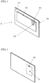
- FIG. 2 is a rear view of the display device 100, which includes a back cover 201.
- the back cover 201 covers the back surface of the display panel 101.
- the back cover 201 is combined with the front panel 102 to hold the display panel 101, and may be made of a resin or metallic material.
- the back cover 201 has a level difference portion 202. If the direction indicated by the arrow shown in FIG. 2 is supposed to be a vertically downward direction, the level difference portion 202 rises substantially perpendicularly to the vertical direction. Or it can also be said that the level difference portion 202 rises substantially perpendicularly to the principal plane that defines the back cover 201.
- the "principal plane” refers herein to a plane which is formed by the four sides of the back cover 201 illustrated in FIG. 2 .
- the shape of the back cover 201 illustrated in FIG. 2 is just an example. And the back cover 201 could have a warped shape or any of various other shapes. That is why in some cases, the "principal plane" could not be defined definitely.
- the display screen of the display panel 101 is generally a planar one as shown in FIG. 1 .
- the position of the level difference portion 202 or any other portion is sometimes defined with respect to the display panel 101.
- the level difference portion 202 projects substantially perpendicularly to the display screen of the display panel 101, or projects rearward in the depth direction, supposing the display panel 101 defines the front.
- a connector 205 to which the attachment 203 is connected.
- the attachment 203 is inserted into the connector 205 substantially parallel to the display screen of the display panel 101.
- An external terminal device 204 is fit into the attachment 203.
- the external terminal device 204 is supposed to have a card shape compliant with the PCMCIA standard, and may be a CI module (CI card) for use to receive a digital telecast in the European district.
- CI card CI module
- the external terminal device 204 has the function of decoding an encrypted broadcast signal that has been received by the display device 100 as will be described in detail later.
- FIG. 2 illustrated is the attachment 203 to which the external terminal device 204 has already been inserted.
- the display device 100, the external terminal device 204, and the attachment 203 to attach the external terminal device 204 to the display device 100 will be sometimes collectively referred to herein as a "display system 10".
- the back cover 201 may have any configuration as long as the back cover 201 defines at least a part of the back surface of the display device 100 and as long as the attachment 203 can be connected to the back cover 201.
- the back cover 201 does not always have to be combined with the front panel 102.
- the level difference portion 202 When viewed from the front of the display panel 101, the level difference portion 202 projects rearward in the depth direction.
- the level difference portion 202 and the back cover 201 are made of the same material.
- the level difference portion 202 may have any other configuration as long as the level difference portion 202 projects from the principal plane of the back cover 201.
- the back cover 201 itself may be flat and another cover including the level difference portion 202 may be connected to the back cover 201.
- the attachment 203 is connected to the connector which is arranged in the level difference portion 202.
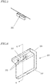
- FIG. 3 illustrates a display system 10 in which the external terminal device 204 has been attached to the display device 100 via the attachment 203.
- the attachment 203 has been inserted into the connector 205 (see FIG. 2 ) that is arranged in the level difference portion 202 of the back cover 201 substantially parallel to the display screen of the display panel 101. This will be described in further detail later.
- FIG. 4 illustrates an internal configuration on the rear side of the display device 100 of the display system 10 according to this embodiment. Specifically, what is illustrated in FIG. 4 with the back cover 201 removed is the rear side of the display device 100. Inside the rear side of the display device 100, there is a board 401 on which the connector 205 is mounted. Also mounted on the board 402 is an electric circuit to process an electrical signal supplied from the connector 205.
- FIG. 5 is a partial enlarged view of the connector 205.
- the connector 205 is positioned so as to present itself on the level difference portion 202 through the hole of the back cover 201 when the back cover 201 is attached to the display device 100.
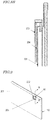
- FIG. 6 is an enlarged view of the attachment 203 according to this embodiment.
- This attachment 203 includes a fitting portion 301 which functions as a first interface, an external terminal device slot 302 which functions as a second interface, insert guides 303, and a bridge portion 304.
- the fitting portion 301 is inserted into the connector 205, and is comprised of a plurality of insert members. By inserting the fitting portion 301 into the slot of the peripheral portion 202, the attachment 203 can be fixed onto the display device 100.
- the external terminal device 204 is fit into the external terminal device slot 302, the external terminal device 204 is fit. By fitting the external terminal device 204 into the external terminal device slot 302, the external terminal device 204 can be fixed onto the attachment 203. When connected to the external terminal device slot 302, part of the external terminal device 204 gets electrically conductive with the fitting portion 301. In this manner, the external terminal device 204 gets connected to the display device 100 to form a circuit together. That is to say, the display device 100 is now ready to use the functions of the external terminal device 100.
- the orientation of the external terminal device slot 302 is defined so that when the attachment 203 is fixed onto the display device 100, the external terminal device 204 that has been fit into the external terminal device slot 302 becomes parallel to the fitting portion 301.
- the insert guides 303 function as guides when the fitting portion 301 is inserted into the connector 205.
- the insert guides 303 are fit into the guide holes 206 (see FIG. 2 ) which are arranged near the connector 205.
- the insert guides 303 also have the function of keeping the fitting portion 301 and the connector 205 connected so that once fit into the connector 205, the fitting portion 301 will not get disconnected from the connector 205.
- the insert guides 303 are positioned so as to contact with the inner peripheral surfaces of the connector 205 when the fitting portion 301 is inserted into the connector 205. In this manner, the connector 205 can be secured with the fitting portion 301 and the insert guides 303 and the fitting portion 301 will not get disconnected from the connector 205 easily.
- the insert guides 303 are arranged parallel to the direction in which the board 401 (see FIG. 4 ) that forms part of an electronic device expands. As a result, the influence on the thickness of the housing of the display device 100 can be minimized.
- the insert guides 303 may have any of various other configurations. But the configuration shown in FIG. 6 can also contribute to reducing the thickness of the display device 100.
- the insert guides 303 of this embodiment are configured to protect the fitting portion 301.
- the insert guides 303 may be longer than, or arranged outside of, the fitting portion 301.
- the former is arranged on the bridge portion 304 opposite from the external terminal device slot 302 with respect to the latter.
- insert guides 303 are supposed to be provided. However, any other number of insert guides 303 may be provided as long as there is at least one insert guide 303. Furthermore, it is not absolutely necessary to provide such insert guides in the first place.
- the bridge portion 304 physically connects the fitting portion 301, the insert guides 304 and the external terminal device slot 302 together. In addition, the bridge portion 304 electrically connects the fitting portion 301 and the external terminal device slot 302 together, too.
- the attachment 203 Due to the presence of this bridge portion 304, the attachment 203 has a substantially U-cross section.
- FIG. 7 is a cross-sectional view of the attachment 203 as viewed on the plane A-A (shown in FIG. 6 ).
- the external terminal device 204 that has been inserted into the external terminal device slot 302 is also shown in FIG. 7 .
- the external terminal device 204 is connected to a group of terminals 701 of the attachment 203 and electrically connected to the fitting portion 301 through a line 702 inside the bridge portion 304.
- FIGS. 8A and 8B how to attach the attachment 203 to the display device 100.
- the user has already inserted the external terminal device 204 into the attachment 203. That is to say, the external terminal device 204 is supposed to be already fixed on the attachment 203.
- FIG. 8A is a cross-sectional view illustrating where the attachment 203 on the verge of being inserted into the display device 100 is positioned.
- the user moves the attachment 203 on which the external terminal device 204 is fixed along either the back cover 201 or the display panel 101 toward the connector 205. And he or she inserts the fitting portion 301 into the connector 205. While inserted and fixed, the attachment 203 can be fixed onto the connector 205 with a portion of the external terminal device 204 and attachment 203 further slid along the back cover 201.
- the external terminal device 204 When the attachment 203 is fixed on the connector 205, the external terminal device 204 will be located close to the back cover 201 as shown in FIG. 8B . However, the external terminal device 204 and the back cover 201 are not located on the same plane but on mutually different planes. The reason is that the bridge portion 304 in substantially a U shape regulates the positions of the fitting portion 301 and the external terminal device slot 302 (i.e., shift them from each other). In this manner, electrical connection is established between them and the display device 100 is now ready to control the external terminal device 204.
- FIG. 9 is a rear view of a display device 110 according to a second embodiment.
- any component having substantially the same function as its counterpart of the display device 100 of the first embodiment is identified by the same reference numeral and will be referred to by the same name.
- a portion of the back cover 201 is supposed to project rearward in the depth direction.
- this embodiment there is a depressed portion 90 in the back cover 201 of the display device 110.
- a plurality of surfaces which forms this depressed portion 90 and which intersects with the display panel at substantially right angles corresponds to the level difference portion 202 of the first embodiment.
- a connector 205 is also arranged in the level difference portion 202.
- FIG. 10 illustrates the display device 110 in which the attachment 203 with the external terminal device 204 already inserted has been fit into the connector 205.
- the external terminal device 204 is supposed to be already fixed on the attachment 203.
- FIG. 11A is a cross-sectional view of the display device 110 as viewed on the plane B-B (shown in FIG. 9 ). As can be seen from FIG. 11A , there is a connector 205 in the level difference portion 202.
- FIG. 11B is a cross-sectional view illustrating where the attachment 203 on the verge of being inserted into the display device 110 is positioned.
- the user puts the fitting portion 301 of the attachment 203 with the external terminal device 204 already inserted into the depressed portion 90 and moves the attachment 203 along either the back cover 201 or the display panel 101 toward the connector 205. And he or she inserts the fitting portion 301 into the connector 205. While inserted and fixed, the attachment 203 can be fixed onto the connector 205 with a portion of the external terminal device 204 and attachment 203 further slid along the back cover 201.
- FIG. 11C is a cross-sectional view illustrating where the attachment 203, of which the fitting portion 301 has been inserted into the connector 205, is located with respect to the display device 110.
- the external terminal device 204 When the attachment 203 is fixed on the connector 205, the external terminal device 204 will be located close to the back cover 201 as shown in FIG. 11C . In this manner, electrical connection is established between them and the display device 110 is now ready to control the external terminal device 204. As already described for the first embodiment, the external terminal device 204 and the back cover 201 are located on mutually different planes for the reason described above.
- Embodiments of the present invention are as described above.
- the user should remove the back cover and attach the electronic device to or around the center of the back surface where the board is arranged. Since it cannot be said that the board can be arranged with a lot of freedom, it has become more and more difficult for the user to access the space reserved for the external terminal device as the size of the display panels becomes bigger and bigger, in particular.
- a level difference portion on the rear of the display device 110 may be arranged in the vicinity of the outer periphery of the back cover and a connector may be arranged in the level difference portion.
- the attachment is supposed to be connected to the board or back cover of the display device while being slid parallel to the board or the back cover instead of being connected perpendicularly to the board or the back cover.
- the user can put weight on the attachment more easily and can handle the attachment more smoothly.
- a connector with a hole that faces vertically upward is provided in the vicinity of the outer periphery of the back cover of the display device.
- the user can insert the attachment while putting weight on the bridge portion vertically downward, and therefore, can insert the attachment very easily.
- the bridge portion of the attachment is at least wide enough for the user to put weight on it easily, then he or she can force the attachment into the connector easily by putting weight onto that bridge portion.
- the weight does not always have to be put vertically downward.
- the display system may also be configured so that the user can put weight laterally or vertically upward.
- the connector is supposed to be provided in either the level difference portion or the depressed portion on the rear of the display device.
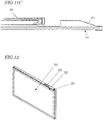
- FIG. 12 illustrates an example in which the connector 205 is arranged on the back cover 201 that defines the upper surface of the display device. The hole of this connector 205 faces vertically upward in this case.
- the display panel 101 and front panel 102 are also shown for your reference.
- neither a level difference portion nor a depressed portion is provided on the back cover 201 in this example.
- the connector 205 does not have to be arranged on the upper surface of display device. Rather, the connector 205 may be arranged on at least one of the upper, lower and side surfaces thereof.
- a display system according to the present invention can be used effectively as a system which is formed by an external terminal device for use to remove a viewing control and a display device.
Landscapes
- Engineering & Computer Science (AREA)
- Multimedia (AREA)
- Signal Processing (AREA)
- Devices For Indicating Variable Information By Combining Individual Elements (AREA)
Claims (10)
- Anzeigesystem, umfassend eine Anzeigevorrichtung (100), eine externe Anschlussvorrichtung (204), und ein Befestigungselement (203) zum Befestigen der externen Anschlussvorrichtung (204) an der Anzeigevorrichtung (100),
wobei die Anzeigevorrichtung (100) umfasst:ein Anzeigepaneel (101); undeine Rückabdeckung (201), die die Rückseite des Anzeigepaneels (101) bedeckt und einen Verbinder (205) umfasst, an dem das Befestigungselement (203) im wesentlichen parallel zu einem Anzeigebildschirm des Anzeigepaneels (101) eingefügt ist, und das Befestigungselement (203) U-förmig ist und umfasst:wobei die Rückabdeckung (201) einen Ebenendifferenzabschnitt (202) umfasst, der eine Oberfläche hat, die sich mit dem Anzeigebildschirm des Anzeigepaneels (101) in im wesentlichen rechten Winkeln schneidet, und der Verbinder (205) auf dieser Oberfläche angeordnet ist.eine erste Schnittstelle (301), die mit dem Verbinder (205) zu verbinden ist;eine zweite Schnittstelle (302), die mit der externen Anschlussvorrichtung (204) zu verbinden ist; undeinen Brückenabschnitt (304), der die erste und die zweite Schnittstelle (301, 302) miteinander elektrisch verbindet und die Positionen der ersten und der zweiten Schnittstelle (301, 302) derart reguliert, dass, wenn die externe Anschlussvorrichtung (204) an der Anzeigevorrichtung (100) über das Befestigungselement (203) angebracht ist, sich die externe Anschlussvorrichtung (204) auf einer anderen Ebene in Bezug auf die Rückabdeckung (201) befindet, - Anzeigesystem nach Anspruch 1, bei dem, wenn die externe Anschlussvorrichtung (204) an der Anzeigevorrichtung (100) über das Befestigungselement (203) angebracht ist, die erste und die zweite Schnittstelle (301, 302) des Befestigungselementes (203) mit dem Verbinder (205) bzw. der externen Anschlussvorrichtung (204) im wesentlichen parallel zu dem Anzeigebildschirm des Anzeigepaneels verbunden sind.
- Anzeigesystem nach Anspruch 1, bei dem der Ebenendifferenzabschnitt (202) senkrecht zu dem Anzeigebildschirm des Anzeigepaneels hervorragt.
- Anzeigesystem nach Anspruch 1, bei dem sich diese Oberfläche zudem mit einer vertikalen Richtung in im wesentlichen rechten Winkeln schneidet.
- Anzeigesystem nach Anspruch 3, bei dem der Verbinder (205) ein Loch hat, das vertikal nach oben gewandt ist.
- Anzeigesystem nach Anspruch 1, bei dem diese Oberfläche in der Nachbarschaft des Außenumfangs der Rückabdeckung (201) angeordnet ist.
- Anzeigesystem nach Anspruch 1, bei dem die Rückabdeckung (201) wenigstens eine der oberen, unteren und seitlichen Oberflächen der Anzeigevorrichtung (100) bildet und der Verbinder (205) auf der wenigstens einen Oberfläche angeordnet ist.
- Anzeigesystem nach Anspruch 1, bei dem die erste Schnittstelle (301) einen Anschluss, der in den Verbinder (205) einzufügen ist, und wenigstens eine Führung (303) umfasst um zu bestimmen, wo der Anschluss in den Verbinder (205) einzufügen ist.
- Befestigungselement für die Befestigung einer externen Anschlussvorrichtung (204) an einer Anzeigevorrichtung (100), wobei die Anzeigevorrichtung (100) umfasst:ein Anzeigepaneel (101); undeine Rückabdeckung (201), die einen Verbinder (205) umfasst, unddas Befestigungselement (203) U-förmig ist und umfasst:eine erste Schnittstelle (301), die mit dem Verbinder (205) zu verbinden ist;eine zweite Schnittstelle (302), die mit der externen Anschlussvorrichtung (204) zu verbinden ist; undeinen Brückenabschnitt (304), der die erste und die zweite Schnittstelle (301, 302) miteinander elektrisch verbindet und die Positionen der ersten und der zweiten Schnittstelle (301, 302) derart reguliert, dass, wenn die externe Anschlussvorrichtung (204) an der Anzeigevorrichtung (100) über das Befestigungselement (203) angebracht ist, sich die externe Anschlussvorrichtung (204) auf einer anderen Ebene in Bezug auf die Rückabdeckung (201) befindet,wobei die Rückabdeckung (201) einen Ebenendifferenzabschnitt (202) umfasst, der eine Oberfläche hat, die sich mit dem Anzeigebildschirm des Anzeigepaneels (101) in im wesentlichen rechten Winkeln schneidet, und der Verbinder (205) auf dieser Oberfläche angeordnet ist.
- Anzeigevorrichtung (100), mit der eine externe Anschlussvorrichtung (204) über ein Verbindungselement (203) verbunden ist,
wobei das Verbindungselement (203) U-förmig ist und umfasst:eine erste Schnittstelle (301), die mit der Anzeigevorrichtung (100) verbunden ist;eine zweite Schnittstelle (302), die mit der externen Anschlussvorrichtung (204) verbunden ist; undeinen Brückenabschnitt (304), der die erste und die zweite Schnittstelle (301, 302) miteinander elektrisch verbindet und die Positionen der ersten und der zweiten Schnittstelle (301, 302) derart reguliert, dass, wenn die externe Anschlussvorrichtung (204) an der Anzeigevorrichtung (100) über das Befestigungselement (203) angebracht ist, sich die externe Anschlussvorrichtung (204) auf einer anderen Ebene in Bezug auf eine Rückabdeckung (201) befindet, unddie Anzeigevorrichtung (100) umfasst:ein Anzeigepaneel (101); unddie Rückabdeckung (201), die die Rückseite des Anzeigepaneels (101) bedeckt und einen Verbinder (205) umfasst, mit dem die erste Schnittstelle (301) des Verbindungselementes (203) im wesentlichen parallel zu einem Anzeigebildschirm des Anzeigepaneels (101) eingefügt ist,wobei die Rückabdeckung (201) einen Ebenendifferenzabschnitt (202) umfasst, der eine Oberfläche hat, die sich mit dem Anzeigebildschirm des Anzeigepaneels (101) in im wesentlichen rechten Winkeln schneidet, und der Verbinder (205) auf dieser Oberfläche angeordnet ist.
Applications Claiming Priority (1)
| Application Number | Priority Date | Filing Date | Title |
|---|---|---|---|
| PCT/JP2012/000468 WO2013111190A1 (ja) | 2012-01-25 | 2012-01-25 | 表示システム、アタッチメントおよび表示装置 |
Publications (3)
| Publication Number | Publication Date |
|---|---|
| EP2809067A1 EP2809067A1 (de) | 2014-12-03 |
| EP2809067A4 EP2809067A4 (de) | 2015-10-21 |
| EP2809067B1 true EP2809067B1 (de) | 2016-12-21 |
Family
ID=48872971
Family Applications (1)
| Application Number | Title | Priority Date | Filing Date |
|---|---|---|---|
| EP12866494.3A Active EP2809067B1 (de) | 2012-01-25 | 2012-01-25 | Anzeigesystem, befestigung und anzeigeeinheit |
Country Status (2)
| Country | Link |
|---|---|
| EP (1) | EP2809067B1 (de) |
| WO (1) | WO2013111190A1 (de) |
Family Cites Families (4)
| Publication number | Priority date | Publication date | Assignee | Title |
|---|---|---|---|---|
| JPH11233964A (ja) * | 1998-02-16 | 1999-08-27 | Sony Computer Entertainment Inc | 電子機器用保護ケース |
| JP2001094272A (ja) * | 1999-09-24 | 2001-04-06 | Yamatake Corp | 電気機器 |
| JP2003288565A (ja) * | 2002-03-27 | 2003-10-10 | Nec Corp | メモリユニットおよびこれを用いる携帯機器 |
| JP4763486B2 (ja) | 2006-03-17 | 2011-08-31 | 株式会社日立製作所 | ケーブルカード装着装置及びテレビジョン受信機 |
-
2012
- 2012-01-25 EP EP12866494.3A patent/EP2809067B1/de active Active
- 2012-01-25 WO PCT/JP2012/000468 patent/WO2013111190A1/ja not_active Ceased
Non-Patent Citations (1)
| Title |
|---|
| None * |
Also Published As
| Publication number | Publication date |
|---|---|
| EP2809067A1 (de) | 2014-12-03 |
| EP2809067A4 (de) | 2015-10-21 |
| WO2013111190A1 (ja) | 2013-08-01 |
Similar Documents
| Publication | Publication Date | Title |
|---|---|---|
| EP3112977B1 (de) | Mobiles endgerät mit mitteln zur verteilung der wärme vom anzeigetreiber | |
| EP2881837B1 (de) | Wasserdichtes Endfunkgerät | |
| US8917515B2 (en) | Electronic device having waterproof and shockproof functions | |
| ES2797373T3 (es) | Dispositivo electrónico que incluye un componente removible | |
| US7878855B2 (en) | Cable connector assembly with a front shell | |
| US8482697B2 (en) | Protecting module and portable electronic device using the same | |
| EP3598722B1 (de) | Mobiles endgerät | |
| JP5417478B2 (ja) | 電子機器 | |
| US9461384B2 (en) | Connection module and mobile terminal having the same | |
| CN101834383B (zh) | 面板连接器组件 | |
| KR20140067811A (ko) | 이동 단말기 | |
| US10139955B2 (en) | Display unit for vehicle and display control unit | |
| EP2908508B1 (de) | Elektronische vorrichtung mit öffnung | |
| KR20160142720A (ko) | 이동 단말기 | |
| EP2712470B1 (de) | Usb-anschluss mit vertikal-zu-horizontal-umwandlungskontakten | |
| US9244488B2 (en) | Display device | |
| CN108666739B (zh) | 天线组件、壳体组件及电子设备 | |
| EP2809067B1 (de) | Anzeigesystem, befestigung und anzeigeeinheit | |
| US10250787B2 (en) | Circuit board assembly and terminal | |
| JP5829642B2 (ja) | 電子機器 | |
| EP1802190A1 (de) | Tragbares funkgerät | |
| CN108232406B (zh) | 天线组件及电子设备 | |
| US20130309894A1 (en) | I/o moudle of electronic device | |
| JP2008199229A (ja) | 外部接続コネクタの補強構造及び該補強構造を備える電子機器 | |
| JP5197806B2 (ja) | 電子機器 |
Legal Events
| Date | Code | Title | Description |
|---|---|---|---|
| PUAI | Public reference made under article 153(3) epc to a published international application that has entered the european phase |
Free format text: ORIGINAL CODE: 0009012 |
|
| 17P | Request for examination filed |
Effective date: 20140730 |
|
| AK | Designated contracting states |
Kind code of ref document: A1 Designated state(s): AL AT BE BG CH CY CZ DE DK EE ES FI FR GB GR HR HU IE IS IT LI LT LU LV MC MK MT NL NO PL PT RO RS SE SI SK SM TR |
|
| DAX | Request for extension of the european patent (deleted) | ||
| RA4 | Supplementary search report drawn up and despatched (corrected) |
Effective date: 20150922 |
|
| RIC1 | Information provided on ipc code assigned before grant |
Ipc: G09F 9/00 20060101ALI20150916BHEP Ipc: H04N 5/64 20060101AFI20150916BHEP Ipc: G06F 1/16 20060101ALI20150916BHEP Ipc: G06F 1/18 20060101ALI20150916BHEP |
|
| GRAP | Despatch of communication of intention to grant a patent |
Free format text: ORIGINAL CODE: EPIDOSNIGR1 |
|
| INTG | Intention to grant announced |
Effective date: 20160708 |
|
| GRAS | Grant fee paid |
Free format text: ORIGINAL CODE: EPIDOSNIGR3 |
|
| GRAA | (expected) grant |
Free format text: ORIGINAL CODE: 0009210 |
|
| AK | Designated contracting states |
Kind code of ref document: B1 Designated state(s): AL AT BE BG CH CY CZ DE DK EE ES FI FR GB GR HR HU IE IS IT LI LT LU LV MC MK MT NL NO PL PT RO RS SE SI SK SM TR |
|
| REG | Reference to a national code |
Ref country code: GB Ref legal event code: FG4D |
|
| REG | Reference to a national code |
Ref country code: CH Ref legal event code: EP |
|
| REG | Reference to a national code |
Ref country code: IE Ref legal event code: FG4D |
|
| REG | Reference to a national code |
Ref country code: AT Ref legal event code: REF Ref document number: 856386 Country of ref document: AT Kind code of ref document: T Effective date: 20170115 |
|
| REG | Reference to a national code |
Ref country code: FR Ref legal event code: PLFP Year of fee payment: 6 |
|
| REG | Reference to a national code |
Ref country code: DE Ref legal event code: R096 Ref document number: 602012026975 Country of ref document: DE |
|
| PG25 | Lapsed in a contracting state [announced via postgrant information from national office to epo] |
Ref country code: LV Free format text: LAPSE BECAUSE OF FAILURE TO SUBMIT A TRANSLATION OF THE DESCRIPTION OR TO PAY THE FEE WITHIN THE PRESCRIBED TIME-LIMIT Effective date: 20161221 |
|
| REG | Reference to a national code |
Ref country code: LT Ref legal event code: MG4D |
|
| REG | Reference to a national code |
Ref country code: NL Ref legal event code: MP Effective date: 20161221 |
|
| PG25 | Lapsed in a contracting state [announced via postgrant information from national office to epo] |
Ref country code: LT Free format text: LAPSE BECAUSE OF FAILURE TO SUBMIT A TRANSLATION OF THE DESCRIPTION OR TO PAY THE FEE WITHIN THE PRESCRIBED TIME-LIMIT Effective date: 20161221 Ref country code: GR Free format text: LAPSE BECAUSE OF FAILURE TO SUBMIT A TRANSLATION OF THE DESCRIPTION OR TO PAY THE FEE WITHIN THE PRESCRIBED TIME-LIMIT Effective date: 20170322 Ref country code: SE Free format text: LAPSE BECAUSE OF FAILURE TO SUBMIT A TRANSLATION OF THE DESCRIPTION OR TO PAY THE FEE WITHIN THE PRESCRIBED TIME-LIMIT Effective date: 20161221 Ref country code: NO Free format text: LAPSE BECAUSE OF FAILURE TO SUBMIT A TRANSLATION OF THE DESCRIPTION OR TO PAY THE FEE WITHIN THE PRESCRIBED TIME-LIMIT Effective date: 20170321 |
|
| REG | Reference to a national code |
Ref country code: AT Ref legal event code: MK05 Ref document number: 856386 Country of ref document: AT Kind code of ref document: T Effective date: 20161221 |
|
| PG25 | Lapsed in a contracting state [announced via postgrant information from national office to epo] |
Ref country code: HR Free format text: LAPSE BECAUSE OF FAILURE TO SUBMIT A TRANSLATION OF THE DESCRIPTION OR TO PAY THE FEE WITHIN THE PRESCRIBED TIME-LIMIT Effective date: 20161221 Ref country code: FI Free format text: LAPSE BECAUSE OF FAILURE TO SUBMIT A TRANSLATION OF THE DESCRIPTION OR TO PAY THE FEE WITHIN THE PRESCRIBED TIME-LIMIT Effective date: 20161221 Ref country code: RS Free format text: LAPSE BECAUSE OF FAILURE TO SUBMIT A TRANSLATION OF THE DESCRIPTION OR TO PAY THE FEE WITHIN THE PRESCRIBED TIME-LIMIT Effective date: 20161221 Ref country code: BE Free format text: LAPSE BECAUSE OF NON-PAYMENT OF DUE FEES Effective date: 20170131 |
|
| PG25 | Lapsed in a contracting state [announced via postgrant information from national office to epo] |
Ref country code: NL Free format text: LAPSE BECAUSE OF FAILURE TO SUBMIT A TRANSLATION OF THE DESCRIPTION OR TO PAY THE FEE WITHIN THE PRESCRIBED TIME-LIMIT Effective date: 20161221 |
|
| PG25 | Lapsed in a contracting state [announced via postgrant information from national office to epo] |
Ref country code: IS Free format text: LAPSE BECAUSE OF FAILURE TO SUBMIT A TRANSLATION OF THE DESCRIPTION OR TO PAY THE FEE WITHIN THE PRESCRIBED TIME-LIMIT Effective date: 20170421 Ref country code: CZ Free format text: LAPSE BECAUSE OF FAILURE TO SUBMIT A TRANSLATION OF THE DESCRIPTION OR TO PAY THE FEE WITHIN THE PRESCRIBED TIME-LIMIT Effective date: 20161221 Ref country code: EE Free format text: LAPSE BECAUSE OF FAILURE TO SUBMIT A TRANSLATION OF THE DESCRIPTION OR TO PAY THE FEE WITHIN THE PRESCRIBED TIME-LIMIT Effective date: 20161221 Ref country code: SK Free format text: LAPSE BECAUSE OF FAILURE TO SUBMIT A TRANSLATION OF THE DESCRIPTION OR TO PAY THE FEE WITHIN THE PRESCRIBED TIME-LIMIT Effective date: 20161221 Ref country code: RO Free format text: LAPSE BECAUSE OF FAILURE TO SUBMIT A TRANSLATION OF THE DESCRIPTION OR TO PAY THE FEE WITHIN THE PRESCRIBED TIME-LIMIT Effective date: 20161221 |
|
| PG25 | Lapsed in a contracting state [announced via postgrant information from national office to epo] |
Ref country code: PT Free format text: LAPSE BECAUSE OF FAILURE TO SUBMIT A TRANSLATION OF THE DESCRIPTION OR TO PAY THE FEE WITHIN THE PRESCRIBED TIME-LIMIT Effective date: 20170421 Ref country code: AT Free format text: LAPSE BECAUSE OF FAILURE TO SUBMIT A TRANSLATION OF THE DESCRIPTION OR TO PAY THE FEE WITHIN THE PRESCRIBED TIME-LIMIT Effective date: 20161221 Ref country code: IT Free format text: LAPSE BECAUSE OF FAILURE TO SUBMIT A TRANSLATION OF THE DESCRIPTION OR TO PAY THE FEE WITHIN THE PRESCRIBED TIME-LIMIT Effective date: 20161221 Ref country code: ES Free format text: LAPSE BECAUSE OF FAILURE TO SUBMIT A TRANSLATION OF THE DESCRIPTION OR TO PAY THE FEE WITHIN THE PRESCRIBED TIME-LIMIT Effective date: 20161221 Ref country code: BG Free format text: LAPSE BECAUSE OF FAILURE TO SUBMIT A TRANSLATION OF THE DESCRIPTION OR TO PAY THE FEE WITHIN THE PRESCRIBED TIME-LIMIT Effective date: 20170321 Ref country code: PL Free format text: LAPSE BECAUSE OF FAILURE TO SUBMIT A TRANSLATION OF THE DESCRIPTION OR TO PAY THE FEE WITHIN THE PRESCRIBED TIME-LIMIT Effective date: 20161221 Ref country code: SM Free format text: LAPSE BECAUSE OF FAILURE TO SUBMIT A TRANSLATION OF THE DESCRIPTION OR TO PAY THE FEE WITHIN THE PRESCRIBED TIME-LIMIT Effective date: 20161221 Ref country code: BE Free format text: LAPSE BECAUSE OF FAILURE TO SUBMIT A TRANSLATION OF THE DESCRIPTION OR TO PAY THE FEE WITHIN THE PRESCRIBED TIME-LIMIT Effective date: 20161221 |
|
| REG | Reference to a national code |
Ref country code: CH Ref legal event code: PL |
|
| REG | Reference to a national code |
Ref country code: DE Ref legal event code: R097 Ref document number: 602012026975 Country of ref document: DE |
|
| PG25 | Lapsed in a contracting state [announced via postgrant information from national office to epo] |
Ref country code: MC Free format text: LAPSE BECAUSE OF FAILURE TO SUBMIT A TRANSLATION OF THE DESCRIPTION OR TO PAY THE FEE WITHIN THE PRESCRIBED TIME-LIMIT Effective date: 20161221 |
|
| PLBE | No opposition filed within time limit |
Free format text: ORIGINAL CODE: 0009261 |
|
| STAA | Information on the status of an ep patent application or granted ep patent |
Free format text: STATUS: NO OPPOSITION FILED WITHIN TIME LIMIT |
|
| PG25 | Lapsed in a contracting state [announced via postgrant information from national office to epo] |
Ref country code: CH Free format text: LAPSE BECAUSE OF NON-PAYMENT OF DUE FEES Effective date: 20170131 Ref country code: LI Free format text: LAPSE BECAUSE OF NON-PAYMENT OF DUE FEES Effective date: 20170131 |
|
| REG | Reference to a national code |
Ref country code: IE Ref legal event code: MM4A |
|
| 26N | No opposition filed |
Effective date: 20170922 |
|
| PG25 | Lapsed in a contracting state [announced via postgrant information from national office to epo] |
Ref country code: LU Free format text: LAPSE BECAUSE OF NON-PAYMENT OF DUE FEES Effective date: 20170125 Ref country code: DK Free format text: LAPSE BECAUSE OF FAILURE TO SUBMIT A TRANSLATION OF THE DESCRIPTION OR TO PAY THE FEE WITHIN THE PRESCRIBED TIME-LIMIT Effective date: 20161221 |
|
| REG | Reference to a national code |
Ref country code: FR Ref legal event code: PLFP Year of fee payment: 7 |
|
| PG25 | Lapsed in a contracting state [announced via postgrant information from national office to epo] |
Ref country code: IE Free format text: LAPSE BECAUSE OF NON-PAYMENT OF DUE FEES Effective date: 20170125 Ref country code: SI Free format text: LAPSE BECAUSE OF FAILURE TO SUBMIT A TRANSLATION OF THE DESCRIPTION OR TO PAY THE FEE WITHIN THE PRESCRIBED TIME-LIMIT Effective date: 20161221 |
|
| PG25 | Lapsed in a contracting state [announced via postgrant information from national office to epo] |
Ref country code: MT Free format text: LAPSE BECAUSE OF NON-PAYMENT OF DUE FEES Effective date: 20170125 |
|
| PG25 | Lapsed in a contracting state [announced via postgrant information from national office to epo] |
Ref country code: HU Free format text: LAPSE BECAUSE OF FAILURE TO SUBMIT A TRANSLATION OF THE DESCRIPTION OR TO PAY THE FEE WITHIN THE PRESCRIBED TIME-LIMIT; INVALID AB INITIO Effective date: 20120125 |
|
| PG25 | Lapsed in a contracting state [announced via postgrant information from national office to epo] |
Ref country code: CY Free format text: LAPSE BECAUSE OF FAILURE TO SUBMIT A TRANSLATION OF THE DESCRIPTION OR TO PAY THE FEE WITHIN THE PRESCRIBED TIME-LIMIT Effective date: 20161221 |
|
| PG25 | Lapsed in a contracting state [announced via postgrant information from national office to epo] |
Ref country code: MK Free format text: LAPSE BECAUSE OF FAILURE TO SUBMIT A TRANSLATION OF THE DESCRIPTION OR TO PAY THE FEE WITHIN THE PRESCRIBED TIME-LIMIT Effective date: 20161221 |
|
| PG25 | Lapsed in a contracting state [announced via postgrant information from national office to epo] |
Ref country code: TR Free format text: LAPSE BECAUSE OF FAILURE TO SUBMIT A TRANSLATION OF THE DESCRIPTION OR TO PAY THE FEE WITHIN THE PRESCRIBED TIME-LIMIT Effective date: 20161221 |
|
| PG25 | Lapsed in a contracting state [announced via postgrant information from national office to epo] |
Ref country code: AL Free format text: LAPSE BECAUSE OF FAILURE TO SUBMIT A TRANSLATION OF THE DESCRIPTION OR TO PAY THE FEE WITHIN THE PRESCRIBED TIME-LIMIT Effective date: 20161221 |
|
| PGFP | Annual fee paid to national office [announced via postgrant information from national office to epo] |
Ref country code: FR Payment date: 20210122 Year of fee payment: 10 |
|
| PG25 | Lapsed in a contracting state [announced via postgrant information from national office to epo] |
Ref country code: FR Free format text: LAPSE BECAUSE OF NON-PAYMENT OF DUE FEES Effective date: 20220131 |
|
| PGFP | Annual fee paid to national office [announced via postgrant information from national office to epo] |
Ref country code: GB Payment date: 20260123 Year of fee payment: 15 |
|
| PGFP | Annual fee paid to national office [announced via postgrant information from national office to epo] |
Ref country code: DE Payment date: 20260121 Year of fee payment: 15 |