EP2809009B1 - Signal encoding and decoding method and device - Google Patents
Signal encoding and decoding method and device Download PDFInfo
- Publication number
- EP2809009B1 EP2809009B1 EP12873219.5A EP12873219A EP2809009B1 EP 2809009 B1 EP2809009 B1 EP 2809009B1 EP 12873219 A EP12873219 A EP 12873219A EP 2809009 B1 EP2809009 B1 EP 2809009B1
- Authority
- EP
- European Patent Office
- Prior art keywords
- frequency domain
- signal
- frequency
- domain signal
- bits
- Prior art date
- Legal status (The legal status is an assumption and is not a legal conclusion. Google has not performed a legal analysis and makes no representation as to the accuracy of the status listed.)
- Active
Links
Images


Classifications
-
- H—ELECTRICITY
- H04—ELECTRIC COMMUNICATION TECHNIQUE
- H04L—TRANSMISSION OF DIGITAL INFORMATION, e.g. TELEGRAPHIC COMMUNICATION
- H04L27/00—Modulated-carrier systems
- H04L27/26—Systems using multi-frequency codes
- H04L27/2601—Multicarrier modulation systems
- H04L27/2602—Signal structure
-
- G—PHYSICS
- G10—MUSICAL INSTRUMENTS; ACOUSTICS
- G10L—SPEECH ANALYSIS TECHNIQUES OR SPEECH SYNTHESIS; SPEECH RECOGNITION; SPEECH OR VOICE PROCESSING TECHNIQUES; SPEECH OR AUDIO CODING OR DECODING
- G10L19/00—Speech or audio signals analysis-synthesis techniques for redundancy reduction, e.g. in vocoders; Coding or decoding of speech or audio signals, using source filter models or psychoacoustic analysis
- G10L19/002—Dynamic bit allocation
-
- G—PHYSICS
- G10—MUSICAL INSTRUMENTS; ACOUSTICS
- G10L—SPEECH ANALYSIS TECHNIQUES OR SPEECH SYNTHESIS; SPEECH RECOGNITION; SPEECH OR VOICE PROCESSING TECHNIQUES; SPEECH OR AUDIO CODING OR DECODING
- G10L19/00—Speech or audio signals analysis-synthesis techniques for redundancy reduction, e.g. in vocoders; Coding or decoding of speech or audio signals, using source filter models or psychoacoustic analysis
- G10L19/02—Speech or audio signals analysis-synthesis techniques for redundancy reduction, e.g. in vocoders; Coding or decoding of speech or audio signals, using source filter models or psychoacoustic analysis using spectral analysis, e.g. transform vocoders or subband vocoders
- G10L19/0204—Speech or audio signals analysis-synthesis techniques for redundancy reduction, e.g. in vocoders; Coding or decoding of speech or audio signals, using source filter models or psychoacoustic analysis using spectral analysis, e.g. transform vocoders or subband vocoders using subband decomposition
-
- G—PHYSICS
- G10—MUSICAL INSTRUMENTS; ACOUSTICS
- G10L—SPEECH ANALYSIS TECHNIQUES OR SPEECH SYNTHESIS; SPEECH RECOGNITION; SPEECH OR VOICE PROCESSING TECHNIQUES; SPEECH OR AUDIO CODING OR DECODING
- G10L19/00—Speech or audio signals analysis-synthesis techniques for redundancy reduction, e.g. in vocoders; Coding or decoding of speech or audio signals, using source filter models or psychoacoustic analysis
- G10L19/02—Speech or audio signals analysis-synthesis techniques for redundancy reduction, e.g. in vocoders; Coding or decoding of speech or audio signals, using source filter models or psychoacoustic analysis using spectral analysis, e.g. transform vocoders or subband vocoders
- G10L19/032—Quantisation or dequantisation of spectral components
-
- G—PHYSICS
- G10—MUSICAL INSTRUMENTS; ACOUSTICS
- G10L—SPEECH ANALYSIS TECHNIQUES OR SPEECH SYNTHESIS; SPEECH RECOGNITION; SPEECH OR VOICE PROCESSING TECHNIQUES; SPEECH OR AUDIO CODING OR DECODING
- G10L19/00—Speech or audio signals analysis-synthesis techniques for redundancy reduction, e.g. in vocoders; Coding or decoding of speech or audio signals, using source filter models or psychoacoustic analysis
- G10L19/04—Speech or audio signals analysis-synthesis techniques for redundancy reduction, e.g. in vocoders; Coding or decoding of speech or audio signals, using source filter models or psychoacoustic analysis using predictive techniques
- G10L19/06—Determination or coding of the spectral characteristics, e.g. of the short-term prediction coefficients
-
- G—PHYSICS
- G10—MUSICAL INSTRUMENTS; ACOUSTICS
- G10L—SPEECH ANALYSIS TECHNIQUES OR SPEECH SYNTHESIS; SPEECH RECOGNITION; SPEECH OR VOICE PROCESSING TECHNIQUES; SPEECH OR AUDIO CODING OR DECODING
- G10L19/00—Speech or audio signals analysis-synthesis techniques for redundancy reduction, e.g. in vocoders; Coding or decoding of speech or audio signals, using source filter models or psychoacoustic analysis
- G10L19/04—Speech or audio signals analysis-synthesis techniques for redundancy reduction, e.g. in vocoders; Coding or decoding of speech or audio signals, using source filter models or psychoacoustic analysis using predictive techniques
- G10L19/16—Vocoder architecture
- G10L19/167—Audio streaming, i.e. formatting and decoding of an encoded audio signal representation into a data stream for transmission or storage purposes
-
- H—ELECTRICITY
- H04—ELECTRIC COMMUNICATION TECHNIQUE
- H04L—TRANSMISSION OF DIGITAL INFORMATION, e.g. TELEGRAPHIC COMMUNICATION
- H04L5/00—Arrangements affording multiple use of the transmission path
- H04L5/02—Channels characterised by the type of signal
- H04L5/06—Channels characterised by the type of signal the signals being represented by different frequencies
-
- G—PHYSICS
- G10—MUSICAL INSTRUMENTS; ACOUSTICS
- G10L—SPEECH ANALYSIS TECHNIQUES OR SPEECH SYNTHESIS; SPEECH RECOGNITION; SPEECH OR VOICE PROCESSING TECHNIQUES; SPEECH OR AUDIO CODING OR DECODING
- G10L19/00—Speech or audio signals analysis-synthesis techniques for redundancy reduction, e.g. in vocoders; Coding or decoding of speech or audio signals, using source filter models or psychoacoustic analysis
- G10L19/04—Speech or audio signals analysis-synthesis techniques for redundancy reduction, e.g. in vocoders; Coding or decoding of speech or audio signals, using source filter models or psychoacoustic analysis using predictive techniques
- G10L19/26—Pre-filtering or post-filtering
Definitions
- the present invention relates to the communications field, and in particular, to methods and devices for signal coding and decoding.
- a coding technology is used at a transmit end to compress a signal to be transmitted, so as to improve the transmission efficiency, and a corresponding decoding technology is used at a receive end to restore the transmitted signal.
- time domain coding and/or frequency domain coding may be performed on the signal. Different bits for coding are allocated to a time domain signal or a frequency domain signal according to a certain rule, and then the signal is coded according to the allocated bits by using a coding method. To improve the signal transmission efficiency, it is expected that a signal to be transmitted is represented by using as few bits for coding as possible. Therefore, the bits for coding need to be allocated properly, so that output signals are restored with least distortion at the receive end by using decoding.
- a coding and decoding effect may generally be good for speech, but the coding and decoding effect is poor for music.
- an input signal is coded by using some bits and by using a time domain coding method; and a frequency domain signal is obtained according to the input signal, and the frequency domain signal is coded by using rest bits and by using a frequency domain coding method.
- the frequency domain signal is coded by using the rest bits, a feature of the signal is generally not considered, and bit allocation is uniformly performed on the frequency domain signal, which leads to a poor coding effect for some frequency domain signals.
- the frequency domain signal is restored by simply using the decoding technology corresponding to the coding technology, noise is filled into a frequency domain signal that is not obtained by decoding, and then frequency domain inverse transformation and time domain synthesis processing are performed to obtain the output signal. Extra noise is introduced when the noise is filled into some signals, which reduces the quality of the output signal.
- US 2007/0244699 A1 discloses an audio signal encoding method for dividing an audio signal into a plurality of sub-band signals, allocating bits to the sub-band signals on a basis of psychoacoustic analysis, and encoding the audio signal.
- US 2007/0276661 A1 discloses an apparatus for encoding digital audio data with reduced bit rates, the apparatus having a provider of psycho-acoustically quantized digital audio data with a bit rate being higher than the reduced bit rate.
- the apparatus further has an identifier for identifying a frequency band according to a selection criterion, the selection criterion being such that an impact on the quality of the digital audio data when the data in the identified frequency band is replaced by generated noise is smaller than the impact on the quality of the digital audio data, which would arise when the data in a different frequency band is replaced by generated noise.
- the apparatus further has a replacer for replacing data in the identified frequency band of the digital audio data by a noise synthesis parameter.
- US 2011/0264454 A1 discloses a method for spectrum recovery in spectral decoding of an audio signal, comprises obtaining of an initial set of spectral coefficients representing the audio signal, and determining a transition frequency.
- the transition frequency is adapted to a spectral content of the audio signal.
- Spectral holes in the initial set of spectral coefficients below the transition frequency are noise filled and the initial set of spectral coefficients are bandwidth extended above the transition frequency.
- US 2011/0305352 A1 discloses a system for generating a high frequency component of a signal from a low frequency component of the signal.
- the system comprises an analysis filter bank providing a plurality of analysis sub-band signals of the low frequency component of the signal. It also comprises a non-linear processing unit to generate a synthesis sub-band signal with a synthesis frequency by modifying the phase of a first and a second of the plurality of analysis sub-band signals and by combining the phase-modified analysis sub-band signals. Finally, it comprises a synthesis filter bank for generating the high frequency component of the signal from the synthesis sub-band signal.
- Juin-Hwey Chen "Adaptive Postfiltering for Quality Enhancement of Coded Speech", IEEE Transactions on Speech and Audio Processing, Vol. 3, No. 1, January 1995, pp. 59 to 71 , discloses an adaptive postfiltering algorithm for enhancing the perceptual quality of coded speech.
- the postfilter consists of a long-term postfilter section in cascade with a short-term postfilter section and includes a spectral tilt compensation and automatic gain control.
- the present invention provides signal coding and decoding methods and devices, where, during coding, bit allocation for a frequency domain signal can be optimized, so as to achieve a better coding effect by using the same number of bits, and during decoding, a frequency domain excitation signal can be extended under the guidance of information obtained by frequency domain decoding, so as to achieve a better effect of an output signal.
- an audio signal coding method includes: obtaining a frequency domain signal according to an input audio signal; allocating predetermined bits to the frequency domain signal according to a predetermined allocation rule, wherein a majority of bits in the predetermined bits are allocated to a low frequency band signal in the frequency domain signal; adjusting the bit allocation for the frequency domain signal when a highest frequency of the frequency domain signal to which bits are allocated is greater than a predetermined value; and coding the frequency domain signal according to the bit allocation for the frequency domain signal, wherein the step of adjusting the bit allocation for the frequency domain signal comprises: reducing the number of bits allocated to a frequency band to which a majority of bits are allocated in the frequency domain signal, and increasing the number of bits allocated to the highest frequency to which bits are allocated and to a frequency domain signal near the highest frequency, wherein the highest frequency of the frequency domain signal to which bits are allocated is a frequency f 2 , the frequency band to which a majority of bits are allocated is in a range of 0 kHz to a frequency
- an audio signal coding device includes: a frequency domain transformation unit, which obtains a frequency domain signal according to an input audio signal; a bit allocation unit, which allocates predetermined bits to the frequency domain signal according to a predetermined allocation rule, wherein a majority of bits in the predetermined bits are allocated to a low frequency band signal in the frequency domain signal; a bit adjustment unit, which adjusts the bit allocation for the frequency domain signal when a highest frequency of the frequency domain signal to which bits are allocated is greater than or equal to a predetermined value; and a frequency domain coding unit, which codes the frequency domain signal according to the bit allocation for the frequency domain signal, wherein the bit adjustment unit is configured to adjust the bit allocation for the frequency domain signal by reducing the number of bits allocated to a frequency band to which a majority of bits are allocated in the frequency domain signal, and increasing the number of bits allocated to the highest frequency to which bits are allocated and to a frequency domain signal near the highest frequency, wherein the highest frequency of the frequency domain signal to which bits are allocated is
- bit allocation for a frequency domain signal is adjusted according to a highest frequency of the frequency domain signal to which bits are allocated, so that a better coding effect is achieved when frequency domain coding is performed by using the same number of bits; and during decoding, a frequency domain signal that is not obtained by decoding is set under the guidance of the frequency domain signal obtained by decoding, so as to achieve a better effect of an output signal.
- a coding technical solution and a decoding technical solution in the present invention may be applied to sending and receiving in various communications systems, where the communications systems are, for example, a GSM, a Code Division Multiple Access (CDMA, Code Division Multiple Access) system, Wideband Code Division Multiple Access (WCDMA, Wideband Code Division Multiple Access Wireless), a General Packet Radio Service (GPRS, General Packet Radio Service), and Long Term Evolution (LTE, Long Term Evolution).
- GSM Global System for Mobile Communications
- CDMA Code Division Multiple Access
- WCDMA Wideband Code Division Multiple Access
- WCDMA Wideband Code Division Multiple Access Wireless
- GPRS General Packet Radio Service
- LTE Long Term Evolution
- the coding technical solution and the decoding technical solution are widely applied to various electronic devices, for example, a mobile phone, a wireless apparatus, a personal data assistant (PDA), a handheld or portable computer, a GPS receiver/navigator, a camera, an audio/video player, a video camera, a video recorder, a monitoring device, and the like.
- this type of electronic device includes an audio coder or an audio decoder, where the audio coder or decoder may be directly implemented by a digital circuit or a chip, for example, a DSP (digital signal processor), or be implemented by that software code drives a processor to perform a procedure in the software code.
- a DSP digital signal processor
- an audio time domain signal is transformed into a frequency domain signal, then a bit for coding is allocated to the audio frequency domain signal for coding, a coded signal is transmitted to a decoding end by using a communications system, and the coded signal is decoded at the decoding end to restore the frequency domain signal.
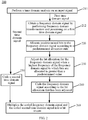
- FIG. 1 shows a signal coding method 100 according to an embodiment of the present invention. As shown in FIG. 1 , the method includes:
- the frequency domain signal is generally divided into sub-bands at an equal interval according to frequencies, or is divided into sub-bands according to frequency domain coefficients, for example, is divided into one sub-band every 16 frequency domain coefficients. For example, for a wideband signal whose frame length is 20 ms, 160 coefficients in a frequency range of 0 to 4 kHz are divided into 10 sub-bands, where there are 5 sub-bands in a frequency range of 0 to 2 kHz, and there are 5 sub-bands in a frequency range of 2 to 4 kHz. Then, bit allocation is performed for each sub-band.
- the more bits whose quantity is 1F_bit are allocated to a low frequency domain signal in the frequency range of 0 to 2 kHz, the number rest_bit of the rest bits is obtained by subtracting 1F_bit from the number tot_bit of the predetermined bits, and the rest bits rest_bit are allocated to the sub-bands in the frequency range of 2 to 4 kHz according to an envelope size of each sub-band in the frequency range of 2 to 4 kHz, where each sub-band has 5 bits.
- the number of sub-bands to which bits are allocated and a sub-band last_bin of a highest frequency band to which bits are allocated are determined according to the rest_bits and the envelope size of each sub-band, and at the same time, a remainder that cannot be exactly divided by 5 is evenly allocated to each sub-band in the range of 0 to 2 kHz.
- the predetermined value B may be set according to an empirical value; in an embodiment, the predetermined value B may be determined according to the bit number tot_bit of the predetermined bits and a resolution of the frequency domain signal (for example, there are 320 frequency domain coefficients in a bandwidth range of 0 to 8 kHz). In the case of a fixed bandwidth, a larger bit number tot_bit of the predetermined bits indicates a larger predetermined value B; and when the bit number tot_bit of the predetermined bits is fixed, a higher resolution of the frequency domain signal indicates a larger predetermined value B.
- the predetermined value B may be determined only according to the bit number tot_bit of the predetermined bits, and a larger bit number tot_bit of the predetermined bits indicates a larger predetermined value B.
- the predetermined value B is a preset upper-limit frequency value. For example, it is estimated according to experience that, after the frequency domain transformation is performed on the input signal, generally no bit is allocated to a frequency domain signal whose frequency is greater than the predetermined value.
- the predetermined value B may be set to a frequency value that is a certain frequency less than a value of the highest frequency of the frequency domain signal, for example, set to 2.9 kHz, 3.2 kHz, 3.5 kHz, or the like.
- the predetermined value B may also be determined according to another factor such as a frame length, a used transformation method, or a transformation window length.
- the predetermined value B may be an index number of 20 sub-bands in a frequency range of 0 to 8 kHz, and the highest frequency of the frequency domain signal to which bits are allocated may also be represented by using an index number of a sub-band in which the highest frequency is located.
- the predetermined value B and the highest frequency of the frequency domain signal to which bits are allocated are not limited to frequency numerical values, and may also be the index numbers of the sub-bands.
- the adjusting the bit allocation for the frequency domain signal may include: reducing the number of bits allocated to a frequency band to which more bits are allocated in the frequency domain signal, and increasing the number of bits allocated to the highest frequency to which bits are allocated and its nearby frequency domain signal.
- the frequency band to which more bits are allocated is a low frequency band of 0 to 2 kHz.
- An adjustment example 1 The highest frequency to which bits are allocated is 4 kHz. If 0 bit is allocated to a sub-band in a range of 2 kHz to 4 kHz, 5 bits are allocated to this frequency band until the number of bits is allocated to all sub-bands in the range of 2 kHz to 4 kHz. It is assumed that the number of bits additionally added in the range of 2 to 4 kHz is N bit . In this case, N bit bits need to be subtracted from the sub-bands in the range of 0 to 2 kHz.
- a used algorithm is that: 1 bit is subtracted from each sub-band in all sub-bands (5 sub-bands) in the range of 0 to 2 kHz, and then a sub-band with the highest frequency is reduced; and 1 bit is subtracted again from each sub-band in the rest 4 sub-bands, and a sub-band with the second highest frequency is reduced again, and the rest is deduced by analogy until the number of bits that are subtracted is equal to N bit .
- the algorithm that may be used is that: N bit /5 bits are subtracted on average from each sub-band in all sub-bands (5 sub-bands) in the range of 0 to 2 kHz.
- An adjustment example 3 5 bits are allocated to each sub-band to which the number of bits is not allocated in the range of 2 kHz to 4 kHz; then J bits are added to all sub-bands in the range of 2 to 4 kHz; if the number of sub-bands to which bits are allocated in the range of 2 to 4 kHz is K, in this case, the number N bit of bits additionally added in the range of 2 to 4 kHz is equal to 5 ⁇ (5-K) + 5 ⁇ J, and N bit bits need to be subtracted from the sub-bands in the range of 0 to 2 kHz.
- a used algorithm may be: any one of the algorithm in the adjustment example 1 and the algorithm in the adjustment example 2.
- the allocation of the predetermined bits that is performed according to the predetermined allocation rule in 120 is maintained.
- bit allocation for a frequency domain signal is adjusted according to a highest frequency of the frequency domain signal to which bits are allocated, so that a better coding effect is achieved when frequency domain coding is performed by using the same number of bits.
- the foregoing signal coding method may be properly applied to various coding solutions, and the following uses an application of the method in time-frequency joint coding as an example for exemplary description.
- FIG. 2 shows a time-frequency joint coding method 200 according to an embodiment of the present invention.
- 220, 230, and 240 are respectively the same as 120, 130, and 140 in FIG. 1 .
- Differences between FIG. 2 and FIG. 1 lie in that, step 250 and step 260 are added, and 110 in FIG. 1 is replaced by 211 and 212. The following describes the differences between FIG. 2 and FIG. 1 , and does not describe the content in common again.
- LSF parameter or the ISF parameter is used to represent a frequency domain feature of a coefficient (that is, an LPC coefficient) that is used in the LPC analysis.
- the residual signal res and the adaptive codebook contribution exc_pit are included in the first time domain signal, and the adaptive codebook contribution exc_pit is included in the second time domain signal.
- the frequency domain transformation is performed separately on the residual signal res and the adaptive codebook contribution exc_pit in the first time domain signal, and then it is determined, according to relevance between a residual signal f res of a frequency domain and an adaptive codebook contribution f exc_pit of the frequency domain, whether the adaptive codebook contribution contributes to an output signal. If the adaptive codebook contribution contributes to the output signal, the adaptive codebook contribution f_exc_pit of the frequency domain is subtracted from the residual signal f res of the frequency domain, to obtain a difference signal f diff of the frequency domain, and the difference signal f diff is used as the frequency domain signal. If the adaptive codebook contribution does not contribute to the output signal, the residual signal f res of the frequency domain is directly used as the difference signal f diff, that is, the frequency domain signal.
- the frequency domain signal is coded by using 220, 230, and 240 that are the same as 120, 130, and 140 in FIG. 1 , to obtain a coded frequency domain signal.
- the time domain signal may be coded by using any time domain coding method (such as prediction coding or pulse code modulation (Pulse Code Modulation, PCM) coding), and a used time domain coding method does not constitute a limitation to the present invention.
- PCM pulse code modulation
- the adaptive codebook contribution contributes to the output signal
- the adaptive codebook contribution needs to be obtained at a decoding end, and therefore, the adaptive codebook contribution exc_pit in the second time domain signal is coded, so that it is transmitted as a bit stream to a receive end.
- the adaptive codebook contribution does not contribute to the output signal, that is, an output at the decoding end does not require the adaptive codebook contribution, this part of time domain coding is not required, improving the coding efficiency. That the adaptive codebook contribution contributes to the output signal means that a high-quality output signal cannot be obtained at the decoding end only according to the coded frequency domain signal.
- the frequency domain signal on which the frequency domain coding needs to be performed may further include another signal, such as a flag (flag) indicating whether the adaptive codebook contribution contributes to the output signal.
- the second time domain signal on which the time domain coding needs to be performed may further include other information required for decoding.
- bit allocation for a frequency domain signal is adjusted according to a highest frequency of the frequency domain signal to which bits are allocated, which is combined with time domain coding, so that a better coding effect is achieved.
- FIG. 3 shows a signal decoding method 300 according to an illustrative example.
- the method 300 includes:
- the predetermined value is determined according to the number tot_bit of predetermined bits used for the frequency domain coding and a resolution of the frequency domain signal.
- the predetermined value may be set to a frequency value that is a certain frequency less than a value of the highest frequency of the frequency domain signal.
- the predetermined value may be an index number of a sub-band, and the highest frequency of the frequency domain signal to which bits are allocated is also represented by using an index number of a sub-band in which the highest frequency domain is located.
- a value of the predetermined value at a decoding end may be the same as or may be different from a value of the predetermined value at a coding end.
- the frequency domain signal obtained by decoding which is obtained by decoding the bit stream in 310, possibly includes the time domain coding signal on which the frequency domain transformation is performed and that contributes to the output signal, and the time domain coding signal on which the frequency domain transformation is performed and that contributes to the output signal, for example, is a signal that is obtained by performing the time domain decoding and the frequency domain transformation on time domain coding information included in the bit stream, such as an adaptive codebook contribution.
- the time domain coding signal on which the frequency domain transformation is performed and that contributes to the output signal may also be another signal except the adaptive codebook contribution.
- the frequency domain signal obtained by decoding includes the adaptive codebook contribution
- it may be learned, according to a flag (flag) indicating whether the foregoing adaptive codebook contribution contributes to the output signal, whether the frequency domain signal obtained by decoding includes the time domain coding signal on which the frequency domain transformation is performed and that contributes to the output signal.
- flag a flag indicating whether the foregoing adaptive codebook contribution contributes to the output signal
- the frequency domain signal obtained by decoding includes the time domain coding signal on which the frequency domain transformation is performed and that contributes to the output signal, which indicates that a high-quality output is difficult to be obtained by only relying on the frequency domain decoding, and according to a feature of a speech/audio signal, in this case, simply setting the frequency domain signal that is not obtained by decoding to noise deteriorates the quality of the output signal, so that the frequency domain signal that is not obtained by decoding needs to be predicted.
- a frequency domain signal of a frequency band may be selected from the highest frequency of the frequency domain signal obtained by decoding to a low frequency, and the frequency domain signal that is not obtained by decoding may be predicted according to the selected frequency domain signal.
- a frequency domain coefficient that is not obtained by decoding in a range of 4 to 6.4 kHz is obtained through prediction by using a frequency domain coefficient that is obtained by decoding in a range of 1.6 to 4 kHz.
- the frequency domain signal that is not obtained by decoding may be predicted by performing normalization processing, envelope processing, and the like on the selected frequency domain signal.
- the implementation of the normalization processing and the envelope processing is a means that is known to a person skilled in the art, and is not described in detail herein.
- a person skilled in the art may predict, by selecting another manner, the frequency domain signal that is not obtained by decoding, for example, may also predict, according to a frequency domain signal in a fixed frequency band in the frequency domain signal obtained by decoding, the frequency domain signal that is not obtained by decoding.
- a predicted frequency domain coefficient that is not obtained by decoding can be corrected by using an ISF parameter or an LSF parameter from the coding end, to prevent the predicted frequency domain signal from including a frequency channel number with excessive energy. For example, a resonant peak location is estimated by using the LSF parameter or the ISF parameter; and at each estimated resonant peak location, a frequency domain coefficient with a greater amplitude is scaled.
- the threshold may be set according to a characteristic of a time domain analysis at the coding end
- the amplitude of the predicted frequency domain coefficient near the resonant peak location is decreased.
- the frequency domain signal that is not obtained by decoding is predicted by using noise.
- 330 Obtain, according to the frequency domain signal obtained by decoding and the predicted frequency domain signal, a time domain signal that is finally outputted.
- the frequency domain signal obtained by decoding is obtained by decoding and the frequency domain signal that is not obtained by decoding is predicted, so as to obtain frequency domain signals in an entire frequency band, an output signal in a time domain is obtained by performing processing such as frequency domain inverse transformation, for example, inverse fast Fourier transform (IFFT, Inverse Fast Fourier Transform).
- IFFT inverse fast Fourier transform
- IFFT Inverse Fast Fourier Transform
- an LPC coefficient is obtained by performing transformation on the ISF parameter or the LSF parameter, time domain synthesis is performed, by using the LPC coefficient, on a signal obtained after the frequency domain inverse transformation, to obtain a time domain signal that is finally outputted.
- time domain synthesis is performed, by using the LPC coefficient, on a signal obtained after the frequency domain inverse transformation, to obtain a time domain signal that is finally outputted.
- a frequency domain signal that is not obtained by decoding is set under the guidance of a frequency domain signal obtained by decoding, so as to achieve a better effect of an output signal.
- the following describes, with reference to FIG. 4 , an application of the decoding method in a time-frequency joint decoding solution.
- the time-frequency joint decoding solution except the step of obtaining, from a received bit stream, a frequency domain signal obtained by decoding (310), subsequent operations are the same as those in 320 and 330 described with reference to FIG. 3 . Therefore, the following only describes how to obtain, in a time-frequency joint decoding method, the frequency domain signal obtained by decoding.
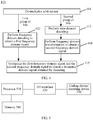
- FIG. 4 shows a method 410 for obtaining, from a received bit stream, a frequency domain signal obtained by decoding in a time-frequency joint decoding method.
- the method 410 includes:
- the first group of bits for example, includes a difference signal f diff, a flag (flag) indicating whether an adaptive codebook contribution contributes to an output signal, and the like.
- the second group of bits for example, includes the adaptive codebook contribution when the adaptive codebook contribution contributes to the output signal. It should be noted that, when encoding the first group of bits and the second group of bits and signal,another signal may further be encoded correspondingly.
- the fourth12 Perform the frequency domain decoding on the first group of bits to obtain a first frequency domain signal, and determine, according to the first frequency domain signal, whether a time domain coding signal that contributes to the output signal exists in the bit stream.
- the first group of bits is decoded by using a decoding method corresponding to a frequency domain coding method at a coding end, to obtain the first frequency domain signal.
- the first frequency domain signal for example, includes a decoded difference signal f diff, and the flag (flag) indicating whether the adaptive codebook contribution contributes to the output signal.
- the second group of bits is decoded by using a decoding method corresponding to a time domain coding method at the coding end, to obtain a decoded time domain signal. Specifically, when it is determined that a time domain coding signal that contributes to the output signal exists in the bit stream, the time domain decoding is performed on the time domain coding signal in the second group of bits.
- the frequency domain signal is obtained through synthesis by adding the difference signal f diff in the first frequency domain signal and the adaptive codebook contribution in the second frequency domain signal.
- the difference signal f diff in the first frequency domain signal is directly used as the frequency domain signal.
- a time domain signal that is finally outputted is obtained by using steps that are the same as 320 and 330 in FIG. 3 .
- the present invention further provides a coding device, where the coding device may be located in a terminal device, a network device, or a test device.
- the coding device may be implemented by a hardware circuit, or be implemented by software in cooperation with hardware.
- FIG. 5 shows exemplary implementation of a coding device and/or a decoding device.
- a processor 510 invokes a coding device or decoding device 530 by using an input/output interface 520, and implements coding or decoding processing of an audio signal with assistance of a memory 540.
- the coding device or decoding device 530 may perform various methods and procedures in the foregoing method embodiments.
- FIG. 6 shows a coding device 600 for signal coding according to an embodiment of the present invention.
- the coding device 600 includes: a frequency domain transformation unit 610, which obtains a frequency domain signal according to an input signal; a bit allocation unit 620, which allocates predetermined bits to the frequency domain signal according to a predetermined allocation rule; a bit adjustment unit 630, which adjusts the bit allocation for the frequency domain signal when a highest frequency of the frequency domain signal to which bits are allocated is greater than or equal to a predetermined value; and a frequency domain coding unit 640, which codes the frequency domain signal according to the bit allocation that has been adjusted.
- the frequency domain transformation unit 610 may obtain the frequency domain signal according to the input signal.
- the input signal may be a signal of various types, such as an image signal, a data signal, an audio signal, a video signal, or a text signal.
- Frequency domain transformation may be performed on the input signal by using an algorithm such as an FFT or a DCT, to obtain the frequency domain signal.
- the type of the input signal and the frequency domain transformation algorithm do not constitute a limitation to the present invention.
- the bit allocation unit 620 may allocate predetermined bits tot bit to the frequency domain signal according to a predetermined allocation rule.
- the tot bit is the number of bits that need to be used for performing coding on the frequency domain signal.
- the predetermined allocation rule may be that: more bits in the predetermined bits are allocated to a low frequency band signal in the frequency domain signal, and rest bits in the predetermined bits are allocated to a frequency band with greater energy except the low frequency band signal.
- the more bits may be uniformly allocated to the low frequency band signal for all low frequency bands or the more bits may be allocated to the low frequency band signal according to energy distribution of the low frequency band signal.
- a reason for allocating the more bits to the low frequency band signal is that, in a frequency domain, an audio signal such as a speech is mainly concentrated in a low frequency range, and allocating the more bits to the audio signal can improve the efficiency of frequency domain coding.
- a frequency domain signal in a frequency range of 0 to 4 kHz is divided into 10 sub-bands, where there are 5 sub-bands in a frequency range of 0 to 2 kHz, and there are 5 sub-bands in a frequency range of 2 to 4 kHz. Then, bit allocation is performed for each sub-band. The more bits whose quantity is 1F_bit are allocated to a low frequency domain signal in the frequency range of 0 to 2 kHz.
- Rest bits rest bit (subtracting 1F_bit from the tot_bit) are allocated to the sub-bands in the frequency range of 2 to 4 kHz according to an envelope of each sub-band in the frequency range of 2 to 4 kHz. Specifically, the number of sub-bands to which bits are allocated and a sub-band last_bin of a highest frequency band to which bits are allocated are determined according to the rest_bits and an envelope size of each sub-band, and at the same time, a remainder that cannot be exactly divided by 5 is evenly allocated to each sub-band in the range of 0 to 2 kHz.
- the bit adjustment unit 630 may adjust the bit allocation for the frequency domain signal when the highest frequency of the frequency domain signal to which bits are allocated is greater than or equal to the predetermined value B.
- the predetermined value B is determined according to the bit number tot_bit of the predetermined bits and a resolution (for example, 4 kHz) of the frequency domain signal.
- the predetermined value is a preset upper-limit frequency value.
- the predetermined value B may be set to a frequency value that is a certain frequency less than a value (for example, 4 kHz) of the highest frequency of the frequency domain signal, for example, set to 2.9 kHz, 3.2 kHz, 3.5 kHz, or the like.
- the predetermined value B may be an index number (for example, 7 or 8) of 10 sub-bands in a frequency range of 0 to 4 kHz, and at this time, the highest frequency of the frequency domain signal to which bits are allocated may also be represented by using an index number index of a sub-band in which the highest frequency is located.
- the bit adjustment unit 630 may adjust the bit allocation for the frequency domain signal that is performed, according to the predetermined allocation rule, by the bit allocation unit 620.
- a frequency domain characteristic of the frequency domain signal, or the like a part that contributes less to an output at a decoding end in the frequency domain signal may be reduced, and bits allocated to the highest frequency to which bits are allocated and its nearby frequency domain signal may accordingly be increased.
- the bit adjustment unit 630 may reduce the number of bits allocated to a frequency band to which more bits are allocated in the frequency domain signal, and increase the number of bits allocated to the highest frequency to which bits are allocated and its nearby frequency domain signal.
- the frequency band to which more bits are allocated is a low frequency band of 0 to 2 kHz.
- the frequency domain coding unit 640 codes the frequency domain signal according to the bit allocation that has been adjusted.
- a method for coding the frequency domain signal for example, may be transformation coding, sub-band coding, or the like.
- the bit adjustment unit 630 does not adjust the bit allocation for the frequency domain signal.
- the bit allocation for the frequency domain signal is bit allocation that is performed according to a predetermined bit allocation rule
- the frequency domain coding unit 640 codes the frequency domain signal according to the bit allocation that is performed according to the predetermined bit allocation rule.
- bit allocation for a frequency domain signal is adjusted according to a highest frequency of the frequency domain signal to which bits are allocated, so that a better coding effect is achieved.
- the coding device 600 may be properly applied to various coding technologies, and the following uses an application of the device in time-frequency joint coding as an example for exemplary description.
- FIG. 7 shows a time-frequency joint coding device 700 using a coding device in an embodiment of the present invention.
- the time-frequency joint coding device 700 includes: a time domain analysis unit 711, which obtains a first time domain signal and a second time domain signal by performing a time domain analysis on an input signal; a frequency domain transformation unit 712, which obtains a frequency domain signal by performing frequency domain transformation and processing on the first time domain signal; a bit allocation unit 720, which allocates predetermined bits to the frequency domain signal according to a predetermined allocation rule; a bit adjustment unit 730, which adjusts the bit allocation for the frequency domain signal when a highest frequency of the frequency domain signal to which bits are allocated is greater than or equal to a predetermined value; a frequency domain coding unit 740, which codes the frequency domain signal according to the bit allocation that has been adjusted; a time domain coding unit 750, which codes the second time domain signal; and a bit multiplexing unit 760, which multiplexes a coded frequency domain signal and a coded second time domain signal into a bit stream.
- a time domain analysis unit 711 which obtains a first time domain signal
- the bit allocation unit 720, the bit adjustment unit 730, and the frequency domain coding unit 740 in FIG. 7 are respectively the same as the bit allocation unit 620, the bit adjustment unit 630, and the frequency domain coding unit 640 in FIG. 6 .
- Differences between FIG. 7 and FIG. 6 lie in that, the time domain coding unit 750 and the bit multiplexing unit 760 are added, and the frequency domain transformation unit 610 in FIG. 6 is replaced by the time domain analysis unit 711 and the frequency domain transformation unit 712. The following describes the differences between FIG. 7 and FIG. 6 , and does not describe the content in common again.
- the time domain analysis unit 711 obtains the first time domain signal and the second time domain signal by performing the time domain analysis on the input signal. For example, an LPC analysis and processing are performed on the input signal to obtain an ISF parameter (or an LSF parameter), a residual signal res, and an adaptive codebook contribution exc_pit. The residual signal res and the adaptive codebook contribution exc_pit are used as the first time domain signal, and the adaptive codebook contribution exc_pit is used as the second time domain signal.
- the frequency domain transformation unit 712 may obtain the frequency domain signal by performing the frequency domain transformation and processing on the first time domain signal.
- the frequency domain transformation is performed separately on the residual signal res and the adaptive codebook contribution exc_pit in the first time domain signal, and then it is determined, according to relevance between a residual signal f res of a frequency domain and an adaptive codebook contribution f_exc_pit of the frequency domain, whether the adaptive codebook contribution contributes to an output signal.
- the adaptive codebook contribution f_exc_pit of the frequency domain is subtracted from the residual signal f res of the frequency domain, to obtain a difference signal f_diff of the frequency domain, and the difference signal f_diff is included in the frequency domain signal. If the adaptive codebook contribution does not contribute to the output signal, the residual signal f res of the frequency domain is directly used as the difference signal f diff and is transmitted as the frequency domain signal. Besides including the difference signal f diff, the frequency domain signal may further include another signal, for example, a flag (flag) indicating whether the adaptive codebook contribution contributes to the output signal.
- a flag indicating whether the adaptive codebook contribution contributes to the output signal.
- the frequency domain signal is coded by using the bit allocation unit 720, the bit adjustment unit 730, and the frequency domain coding unit 740 in FIG. 7 , to obtain a coded frequency domain signal.
- the time domain coding unit 750 may code the second time domain signal.
- the time domain signal may be coded by using a time domain coding method such as prediction coding or pulse code modulation.
- a time domain coding method such as prediction coding or pulse code modulation.
- the adaptive codebook contribution contributes to the output signal
- the adaptive codebook contribution needs to be obtained at a decoding end, and therefore, the adaptive codebook contribution exc_pit in the second time domain signal is coded, so that it is transmitted to a receive end.
- the adaptive codebook contribution does not contribute to the output signal, the adaptive codebook contribution does not need to be coded and transmitted, improving the coding efficiency.
- the bit multiplexing unit 760 may multiplex the coded frequency domain signal and the coded second time domain signal into the bit stream.
- bit allocation for a frequency domain signal is adjusted according to a highest frequency of the frequency domain signal to which bits are allocated, which is combined with time domain coding, so that a better coding effect is achieved.
- FIG. 8 shows a decoding device 800 for signal decoding according to illustrative example.
- the decoding device 800 includes: a decoding unit 810, which obtains, from a received bit stream, a frequency domain signal obtained by decoding; a bandwidth extension unit 820, configured to predict a frequency domain signal that is not obtained by decoding, and when the frequency domain signal obtained by decoding meets a predetermined condition, predict, according to the frequency domain signal obtained by decoding, the frequency domain signal that is not obtained by decoding; and an output unit 830, which obtains, according to the frequency domain signal obtained by decoding and the predicted frequency domain signal, a time domain signal that is finally outputted.
- a decoding unit 810 which obtains, from a received bit stream, a frequency domain signal obtained by decoding
- a bandwidth extension unit 820 configured to predict a frequency domain signal that is not obtained by decoding, and when the frequency domain signal obtained by decoding meets a predetermined condition, predict, according to the frequency domain signal obtained by decoding, the frequency domain signal
- the decoding unit 810 may obtain, from the received bit stream, the frequency domain signal obtained by decoding.
- the frequency domain signal obtained by decoding is obtained from the received bit stream.
- the decoding unit 810 may obtain, from the received bit stream by performing the following operations, the frequency domain signal obtained by decoding: performing frequency domain decoding on frequency domain information in the bit stream to obtain a first frequency domain signal; determining, according to the first frequency domain signal, whether a time domain coding signal that contributes to an output signal exists in the bit stream; when it is determined that a time domain coding signal that contributes to the output signal exists in the bit stream, performing time domain decoding and frequency domain transformation on the time domain coding signal to obtain a second frequency domain signal, and synthesizing the first frequency domain signal and the second frequency domain signal to obtain the frequency domain signal obtained by decoding. This is described below in detail with reference to FIG. 9 .
- the bandwidth extension unit 820 may be configured to predict the frequency domain signal that is not obtained by decoding.
- the bandwidth extension unit 820 may predict, according to the frequency domain signal obtained by decoding, the frequency domain signal that is not obtained by decoding.
- that the frequency domain signal obtained by decoding meets a predetermined condition includes at least one of the following: a highest frequency of the frequency domain signal obtained by decoding is greater than a predetermined value, and the frequency domain signal obtained by decoding includes a time domain coding signal on which the frequency domain transformation is performed and that contributes to the output signal.
- selection may be performed according to a need.
- the predetermined value may be determined according to the number tot_bit of predetermined bits used for the frequency domain coding and a resolution of the frequency domain signal. According to a need of practice, the predetermined value may be set to a frequency value that is a certain frequency less than a value of the highest frequency of the frequency domain signal.
- the predetermined value may be an index number of a sub-band, and the highest frequency of the frequency domain signal to which bits are allocated is also represented by using an index number of a sub-band in which the highest frequency domain is located.
- the frequency domain signal obtained by decoding which is obtained by the decoding unit 810 by decoding the bit stream, possibly includes a signal that is obtained by performing the time domain decoding and the frequency domain transformation on time domain information included in the bit stream, for example, an adaptive codebook contribution. It may be learned, according to a flag (flag) indicating whether the foregoing adaptive codebook contribution contributes to the output signal, whether the frequency domain signal includes the time domain coding signal on which the frequency domain transformation is performed and that contributes to the output signal. According to different types of coded signals and when a time domain analysis method used during the coding is not an LPC analysis, the time domain coding signal on which the frequency domain transformation is performed and that contributes to the output signal may also be another signal.
- the frequency domain signal obtained by decoding includes the signal that is obtained by performing the time domain decoding and the frequency domain transformation on the time domain information included in the bit stream, which indicates that the frequency domain signal that is not obtained by decoding includes information that is useful to an output, so that the frequency domain signal that is not obtained by decoding needs to be predicted, and simply setting the frequency domain signal that is not obtained by decoding to noise deteriorates the quality of an output signal.
- the bandwidth extension unit 820 may set the frequency domain signal that is not obtained by decoding to the noise.
- the bandwidth extension unit 820 may select a frequency domain signal of a frequency band from the highest frequency of the frequency domain signal obtained by decoding to a low frequency, and process the selected frequency domain signal as described above, so as to predict, according to the selected frequency domain signal, the frequency domain signal that is not obtained by decoding.
- the frequency domain signal that is not obtained by decoding may also be predicted by using another manner, for example, the frequency domain signal that is not obtained by decoding may also be predicted according to a frequency domain signal in a fixed frequency band in the frequency domain signal obtained by decoding.
- the output unit 830 may obtain, according to the frequency domain signal obtained by decoding and the predicted frequency domain signal, the time domain signal that is finally outputted. After the frequency domain signal that is not obtained by decoding is predicted, frequency domain signals in an entire frequency band are obtained, and frequency domain inverse transformation is performed on frequency domain signals in an entire bandwidth by using inverse transformation of the frequency domain transformation used during the coding, so that an output signal in a time domain is obtained. As described above, the output unit may perform a time domain synthesis, by using an LPC coefficient that is obtained according to an ISF parameter (or an LSF parameter), on a signal after the frequency domain inverse transformation, to obtain the time domain signal that is finally outputted for outputting.
- an ISF parameter or an LSF parameter
- a frequency domain signal that is not obtained by decoding is set under the guidance of a frequency domain signal obtained by decoding, so as to make an output signal achieves a better effect.
- FIG. 9 shows a block diagram of a decoding unit 910 in time-frequency joint decoding.
- the decoding unit 910 includes: a de-multiplexing unit 911, which de-multiplexes a bit stream into a first group of bits and a second group of bits; a frequency domain decoding unit 912, which performs frequency domain decoding on the first group of bits to obtain a first frequency domain signal, and determines, according to the first frequency domain signal, whether a time domain coding signal that contributes to an output signal exists in the bit stream; a time domain decoding unit 913, which performs time domain decoding in the second group of bits if it is determined that a time domain coding signal that contributes to the output signal exists in the bit stream; a frequency domain transformation unit 914, which performs frequency domain transformation on a decoded time domain signal to obtain a second frequency domain signal; and a synthesis unit 915, which synthesizes the first frequency domain signal and the second frequency domain signal to obtain a frequency domain signal obtained by decoding.
- the de-multiplexing unit 911 For the purpose of convenient and brief description, for specific operations of the de-multiplexing unit 911, the frequency domain decoding unit 912, the time domain decoding unit 913, the frequency domain transformation unit 914, or the synthesis unit 915, refer to 411, 412, 413, 414, and 415 in FIG. 4 , which are not be described in detail herein again.
- the disclosed device and method may be implemented in other manners.
- the described device embodiment is merely exemplary.
- the unit division is merely logical function division and may be other division in actual implementation.
- multiple units or components may be combined or integrated into another system, or some features may be ignored or not performed.
- the units described as separate parts may or may not be physically separate, may be located in one position, or may be distributed on multiple network units. A part or all of the units may be selected as required to achieve objectives of the solutions of the embodiments.
- the functions When the functions are implemented in a form of a software functional unit and sold or used as an independent product, the functions may be stored in a computer-readable storage medium. Based on such an understanding, the technical solutions of the present invention essentially, or the part contributing to the prior art, or a part of the technical solutions may be implemented in a form of a software product.
- the computer software product is stored in a storage medium, and includes several instructions for instructing a computer device (which may be a personal computer, a server, a network device, or the like) to perform all or a part of the steps of the methods described in the embodiments of the present invention.
- the foregoing storage medium includes: any medium that can store program code, such as a USB flash drive, a removable hard disk, a read-only memory (ROM, Read-Only Memory), a random access memory (RAM, Random Access Memory), a magnetic disk, or an optical disc.
- program code such as a USB flash drive, a removable hard disk, a read-only memory (ROM, Read-Only Memory), a random access memory (RAM, Random Access Memory), a magnetic disk, or an optical disc.
Landscapes
- Engineering & Computer Science (AREA)
- Physics & Mathematics (AREA)
- Signal Processing (AREA)
- Computational Linguistics (AREA)
- Health & Medical Sciences (AREA)
- Audiology, Speech & Language Pathology (AREA)
- Human Computer Interaction (AREA)
- Acoustics & Sound (AREA)
- Multimedia (AREA)
- Spectroscopy & Molecular Physics (AREA)
- Computer Networks & Wireless Communication (AREA)
- Compression, Expansion, Code Conversion, And Decoders (AREA)
Priority Applications (2)
| Application Number | Priority Date | Filing Date | Title |
|---|---|---|---|
| EP17160983.7A EP3249645B1 (en) | 2012-03-29 | 2012-05-23 | Signal coding and decoding methods and devices |
| EP19191869.7A EP3664085B1 (en) | 2012-03-29 | 2012-05-23 | Signal coding and decoding methods and devices |
Applications Claiming Priority (2)
| Application Number | Priority Date | Filing Date | Title |
|---|---|---|---|
| CN201210087702.9A CN103368682B (zh) | 2012-03-29 | 2012-03-29 | 信号编码和解码的方法和设备 |
| PCT/CN2012/075924 WO2013143221A1 (zh) | 2012-03-29 | 2012-05-23 | 信号编码和解码的方法和设备 |
Related Child Applications (3)
| Application Number | Title | Priority Date | Filing Date |
|---|---|---|---|
| EP17160983.7A Division-Into EP3249645B1 (en) | 2012-03-29 | 2012-05-23 | Signal coding and decoding methods and devices |
| EP17160983.7A Division EP3249645B1 (en) | 2012-03-29 | 2012-05-23 | Signal coding and decoding methods and devices |
| EP19191869.7A Division EP3664085B1 (en) | 2012-03-29 | 2012-05-23 | Signal coding and decoding methods and devices |
Publications (3)
| Publication Number | Publication Date |
|---|---|
| EP2809009A1 EP2809009A1 (en) | 2014-12-03 |
| EP2809009A4 EP2809009A4 (en) | 2015-07-15 |
| EP2809009B1 true EP2809009B1 (en) | 2017-11-29 |
Family
ID=49258139
Family Applications (3)
| Application Number | Title | Priority Date | Filing Date |
|---|---|---|---|
| EP12873219.5A Active EP2809009B1 (en) | 2012-03-29 | 2012-05-23 | Signal encoding and decoding method and device |
| EP19191869.7A Active EP3664085B1 (en) | 2012-03-29 | 2012-05-23 | Signal coding and decoding methods and devices |
| EP17160983.7A Active EP3249645B1 (en) | 2012-03-29 | 2012-05-23 | Signal coding and decoding methods and devices |
Family Applications After (2)
| Application Number | Title | Priority Date | Filing Date |
|---|---|---|---|
| EP19191869.7A Active EP3664085B1 (en) | 2012-03-29 | 2012-05-23 | Signal coding and decoding methods and devices |
| EP17160983.7A Active EP3249645B1 (en) | 2012-03-29 | 2012-05-23 | Signal coding and decoding methods and devices |
Country Status (15)
| Country | Link |
|---|---|
| US (4) | US9537694B2 (pl) |
| EP (3) | EP2809009B1 (pl) |
| JP (2) | JP6006400B2 (pl) |
| KR (1) | KR101621641B1 (pl) |
| CN (3) | CN110706715B (pl) |
| BR (1) | BR112014023577B8 (pl) |
| CA (2) | CA2866202C (pl) |
| ES (3) | ES2927563T3 (pl) |
| MX (1) | MX339652B (pl) |
| PL (1) | PL3664085T3 (pl) |
| PT (1) | PT3249645T (pl) |
| RU (1) | RU2592412C2 (pl) |
| SG (2) | SG10201701275XA (pl) |
| WO (1) | WO2013143221A1 (pl) |
| ZA (1) | ZA201406424B (pl) |
Families Citing this family (17)
| Publication number | Priority date | Publication date | Assignee | Title |
|---|---|---|---|---|
| US10916317B2 (en) | 2010-08-20 | 2021-02-09 | Attopsemi Technology Co., Ltd | Programmable resistance memory on thin film transistor technology |
| US10923204B2 (en) | 2010-08-20 | 2021-02-16 | Attopsemi Technology Co., Ltd | Fully testible OTP memory |
| US9818478B2 (en) | 2012-12-07 | 2017-11-14 | Attopsemi Technology Co., Ltd | Programmable resistive device and memory using diode as selector |
| US10586832B2 (en) | 2011-02-14 | 2020-03-10 | Attopsemi Technology Co., Ltd | One-time programmable devices using gate-all-around structures |
| CN110706715B (zh) | 2012-03-29 | 2022-05-24 | 华为技术有限公司 | 信号编码和解码的方法和设备 |
| CN105374363B (zh) * | 2014-08-25 | 2019-06-04 | 广东美的集团芜湖制冷设备有限公司 | 音频信号编码方法和系统 |
| US10726914B2 (en) | 2017-04-14 | 2020-07-28 | Attopsemi Technology Co. Ltd | Programmable resistive memories with low power read operation and novel sensing scheme |
| US11062786B2 (en) | 2017-04-14 | 2021-07-13 | Attopsemi Technology Co., Ltd | One-time programmable memories with low power read operation and novel sensing scheme |
| US11615859B2 (en) | 2017-04-14 | 2023-03-28 | Attopsemi Technology Co., Ltd | One-time programmable memories with ultra-low power read operation and novel sensing scheme |
| US10535413B2 (en) | 2017-04-14 | 2020-01-14 | Attopsemi Technology Co., Ltd | Low power read operation for programmable resistive memories |
| JP6934648B2 (ja) * | 2017-07-03 | 2021-09-15 | 東日本旅客鉄道株式会社 | トロリ線曲げ工具 |
| KR102383195B1 (ko) | 2017-10-27 | 2022-04-08 | 프라운호퍼-게젤샤프트 추르 푀르데룽 데어 안제반텐 포르슝 에 파우 | 디코더에서의 노이즈 감쇠 |
| US10770160B2 (en) | 2017-11-30 | 2020-09-08 | Attopsemi Technology Co., Ltd | Programmable resistive memory formed by bit slices from a standard cell library |
| US12483429B2 (en) | 2021-06-01 | 2025-11-25 | Attopsemi Technology Co., Ltd | Physically unclonable function produced using OTP memory |
| CN115148217B (zh) * | 2022-06-15 | 2024-07-09 | 腾讯科技(深圳)有限公司 | 音频处理方法、装置、电子设备、存储介质及程序产品 |
| WO2024050673A1 (zh) * | 2022-09-05 | 2024-03-14 | 北京小米移动软件有限公司 | 一种音频信号频带扩展方法、装置、设备及存储介质 |
| CN118053437A (zh) * | 2022-11-17 | 2024-05-17 | 抖音视界有限公司 | 音频编码方法、解码方法、装置、设备及存储介质 |
Family Cites Families (50)
| Publication number | Priority date | Publication date | Assignee | Title |
|---|---|---|---|---|
| US5517511A (en) * | 1992-11-30 | 1996-05-14 | Digital Voice Systems, Inc. | Digital transmission of acoustic signals over a noisy communication channel |
| JP3131542B2 (ja) | 1993-11-25 | 2001-02-05 | シャープ株式会社 | 符号化復号化装置 |
| KR970011727B1 (en) * | 1994-11-09 | 1997-07-14 | Daewoo Electronics Co Ltd | Apparatus for encoding of the audio signal |
| JP3521596B2 (ja) | 1996-01-30 | 2004-04-19 | ソニー株式会社 | 信号符号化方法 |
| JP3519859B2 (ja) * | 1996-03-26 | 2004-04-19 | 三菱電機株式会社 | 符号器及び復号器 |
| FI970553L (fi) | 1997-02-07 | 1998-08-08 | Nokia Mobile Phones Ltd | Audiokoodausmenetelmä ja -laite |
| US6356211B1 (en) | 1997-05-13 | 2002-03-12 | Sony Corporation | Encoding method and apparatus and recording medium |
| KR100335609B1 (ko) * | 1997-11-20 | 2002-10-04 | 삼성전자 주식회사 | 비트율조절이가능한오디오부호화/복호화방법및장치 |
| KR100304092B1 (ko) * | 1998-03-11 | 2001-09-26 | 마츠시타 덴끼 산교 가부시키가이샤 | 오디오 신호 부호화 장치, 오디오 신호 복호화 장치 및 오디오 신호 부호화/복호화 장치 |
| US6226616B1 (en) | 1999-06-21 | 2001-05-01 | Digital Theater Systems, Inc. | Sound quality of established low bit-rate audio coding systems without loss of decoder compatibility |
| US6621935B1 (en) * | 1999-12-03 | 2003-09-16 | Microsoft Corporation | System and method for robust image representation over error-prone channels |
| JP2001255882A (ja) | 2000-03-09 | 2001-09-21 | Sony Corp | 音声信号処理装置及びその信号処理方法 |
| SE0001926D0 (sv) * | 2000-05-23 | 2000-05-23 | Lars Liljeryd | Improved spectral translation/folding in the subband domain |
| JP2004522198A (ja) | 2001-05-08 | 2004-07-22 | コーニンクレッカ フィリップス エレクトロニクス エヌ ヴィ | 音声符号化方法 |
| US7333929B1 (en) * | 2001-09-13 | 2008-02-19 | Chmounk Dmitri V | Modular scalable compressed audio data stream |
| CN1127054C (zh) * | 2001-11-02 | 2003-11-05 | 北京阜国数字技术有限公司 | 用于知觉音频编码的信号处理方法 |
| US20030187663A1 (en) * | 2002-03-28 | 2003-10-02 | Truman Michael Mead | Broadband frequency translation for high frequency regeneration |
| DE10328777A1 (de) * | 2003-06-25 | 2005-01-27 | Coding Technologies Ab | Vorrichtung und Verfahren zum Codieren eines Audiosignals und Vorrichtung und Verfahren zum Decodieren eines codierten Audiosignals |
| US7349842B2 (en) * | 2003-09-29 | 2008-03-25 | Sony Corporation | Rate-distortion control scheme in audio encoding |
| US7672838B1 (en) * | 2003-12-01 | 2010-03-02 | The Trustees Of Columbia University In The City Of New York | Systems and methods for speech recognition using frequency domain linear prediction polynomials to form temporal and spectral envelopes from frequency domain representations of signals |
| US7586924B2 (en) * | 2004-02-27 | 2009-09-08 | Fraunhofer-Gesellschaft Zur Foerderung Der Angewandten Forschung E.V. | Apparatus and method for coding an information signal into a data stream, converting the data stream and decoding the data stream |
| EP1873753A1 (en) * | 2004-04-01 | 2008-01-02 | Beijing Media Works Co., Ltd | Enhanced audio encoding/decoding device and method |
| KR100723400B1 (ko) | 2004-05-12 | 2007-05-30 | 삼성전자주식회사 | 복수의 룩업테이블을 이용한 디지털 신호 부호화 방법 및장치 |
| US7860721B2 (en) * | 2004-09-17 | 2010-12-28 | Panasonic Corporation | Audio encoding device, decoding device, and method capable of flexibly adjusting the optimal trade-off between a code rate and sound quality |
| WO2006049205A1 (ja) * | 2004-11-05 | 2006-05-11 | Matsushita Electric Industrial Co., Ltd. | スケーラブル復号化装置およびスケーラブル符号化装置 |
| DE602006015294D1 (de) * | 2005-03-30 | 2010-08-19 | Dolby Int Ab | Mehrkanal-audiocodierung |
| KR100851972B1 (ko) * | 2005-10-12 | 2008-08-12 | 삼성전자주식회사 | 오디오 데이터 및 확장 데이터 부호화/복호화 방법 및 장치 |
| JP2007149151A (ja) * | 2005-11-24 | 2007-06-14 | Funai Electric Co Ltd | 光ディスク再生装置、音声信号出力装置及びavシステム |
| KR101237413B1 (ko) * | 2005-12-07 | 2013-02-26 | 삼성전자주식회사 | 오디오 신호의 부호화 및 복호화 방법, 오디오 신호의부호화 및 복호화 장치 |
| US20090281812A1 (en) * | 2006-01-18 | 2009-11-12 | Lg Electronics Inc. | Apparatus and Method for Encoding and Decoding Signal |
| JP2007264154A (ja) * | 2006-03-28 | 2007-10-11 | Sony Corp | オーディオ信号符号化方法、オーディオ信号符号化方法のプログラム、オーディオ信号符号化方法のプログラムを記録した記録媒体及びオーディオ信号符号化装置 |
| WO2007121778A1 (en) * | 2006-04-24 | 2007-11-01 | Nero Ag | Advanced audio coding apparatus |
| KR20070115637A (ko) * | 2006-06-03 | 2007-12-06 | 삼성전자주식회사 | 대역폭 확장 부호화 및 복호화 방법 및 장치 |
| JP4396683B2 (ja) * | 2006-10-02 | 2010-01-13 | カシオ計算機株式会社 | 音声符号化装置、音声符号化方法、及び、プログラム |
| KR101565919B1 (ko) * | 2006-11-17 | 2015-11-05 | 삼성전자주식회사 | 고주파수 신호 부호화 및 복호화 방법 및 장치 |
| RU2406165C2 (ru) * | 2007-02-14 | 2010-12-10 | ЭлДжи ЭЛЕКТРОНИКС ИНК. | Способы и устройства для кодирования и декодирования объектно-базированных аудиосигналов |
| MX2010001394A (es) * | 2007-08-27 | 2010-03-10 | Ericsson Telefon Ab L M | Frecuencia de transicion adaptiva entre llenado de ruido y extension de anchura de banda. |
| KR100970446B1 (ko) | 2007-11-21 | 2010-07-16 | 한국전자통신연구원 | 주파수 확장을 위한 가변 잡음레벨 결정 장치 및 그 방법 |
| CN101436407B (zh) | 2008-12-22 | 2011-08-24 | 西安电子科技大学 | 音频编解码方法 |
| AU2010205583B2 (en) * | 2009-01-16 | 2013-02-07 | Dolby International Ab | Cross product enhanced harmonic transposition |
| CN101494054B (zh) * | 2009-02-09 | 2012-02-15 | 华为终端有限公司 | 一种音频码率控制方法及系统 |
| PL2273493T3 (pl) * | 2009-06-29 | 2013-07-31 | Fraunhofer Ges Forschung | Kodowanie i dekodowanie z rozszerzaniem szerokości pasma |
| CN101958119B (zh) * | 2009-07-16 | 2012-02-29 | 中兴通讯股份有限公司 | 一种改进的离散余弦变换域音频丢帧补偿器和补偿方法 |
| RU2591663C2 (ru) | 2009-10-20 | 2016-07-20 | Фраунхофер-Гезелльшафт цур Фёрдерунг дер ангевандтен Форшунг Е.Ф. | Аудио кодер, аудио декодер, способ кодирования аудио информации, способ декодирования аудио информации и компьютерная программа, использующая обнаружение группы ранее декодированных спектральных значений |
| CN102081927B (zh) * | 2009-11-27 | 2012-07-18 | 中兴通讯股份有限公司 | 一种可分层音频编码、解码方法及系统 |
| BR122021008576B1 (pt) * | 2010-01-12 | 2022-04-12 | Fraunhofer-Gesellschaft zur Förderung der angewandten Forschung e.V | Codificador de áudio, decodificador de áudio, método de codificação e informação de áudio, e método de decodificação de uma informação de áudio que utiliza uma tabela hash que descreve tanto valores de estado significativos como limites de intervalo |
| US8751225B2 (en) * | 2010-05-12 | 2014-06-10 | Electronics And Telecommunications Research Institute | Apparatus and method for coding signal in a communication system |
| US9047875B2 (en) * | 2010-07-19 | 2015-06-02 | Futurewei Technologies, Inc. | Spectrum flatness control for bandwidth extension |
| CN102208188B (zh) | 2011-07-13 | 2013-04-17 | 华为技术有限公司 | 音频信号编解码方法和设备 |
| CN110706715B (zh) | 2012-03-29 | 2022-05-24 | 华为技术有限公司 | 信号编码和解码的方法和设备 |
-
2012
- 2012-03-29 CN CN201910973689.9A patent/CN110706715B/zh active Active
- 2012-03-29 CN CN201610881546.1A patent/CN106409299B/zh active Active
- 2012-03-29 CN CN201210087702.9A patent/CN103368682B/zh active Active
- 2012-05-23 BR BR112014023577A patent/BR112014023577B8/pt active Search and Examination
- 2012-05-23 SG SG10201701275XA patent/SG10201701275XA/en unknown
- 2012-05-23 MX MX2014011605A patent/MX339652B/es active IP Right Grant
- 2012-05-23 ES ES19191869T patent/ES2927563T3/es active Active
- 2012-05-23 SG SG11201405216SA patent/SG11201405216SA/en unknown
- 2012-05-23 CA CA2866202A patent/CA2866202C/en active Active
- 2012-05-23 CA CA2994705A patent/CA2994705C/en active Active
- 2012-05-23 EP EP12873219.5A patent/EP2809009B1/en active Active
- 2012-05-23 ES ES12873219.5T patent/ES2655832T3/es active Active
- 2012-05-23 PL PL19191869.7T patent/PL3664085T3/pl unknown
- 2012-05-23 RU RU2014142255/08A patent/RU2592412C2/ru active
- 2012-05-23 EP EP19191869.7A patent/EP3664085B1/en active Active
- 2012-05-23 WO PCT/CN2012/075924 patent/WO2013143221A1/zh not_active Ceased
- 2012-05-23 JP JP2015502053A patent/JP6006400B2/ja active Active
- 2012-05-23 ES ES17160983T patent/ES2770831T3/es active Active
- 2012-05-23 KR KR1020147026193A patent/KR101621641B1/ko active Active
- 2012-05-23 EP EP17160983.7A patent/EP3249645B1/en active Active
- 2012-05-23 PT PT171609837T patent/PT3249645T/pt unknown
-
2014
- 2014-09-01 ZA ZA2014/06424A patent/ZA201406424B/en unknown
- 2014-09-25 US US14/496,986 patent/US9537694B2/en active Active
-
2016
- 2016-09-08 JP JP2016175647A patent/JP6323881B2/ja active Active
- 2016-11-22 US US15/358,649 patent/US9786293B2/en active Active
-
2017
- 2017-08-23 US US15/684,079 patent/US9899033B2/en active Active
-
2018
- 2018-01-08 US US15/864,147 patent/US10600430B2/en active Active
Non-Patent Citations (1)
| Title |
|---|
| None * |
Also Published As
Similar Documents
| Publication | Publication Date | Title |
|---|---|---|
| EP2809009B1 (en) | Signal encoding and decoding method and device | |
| EP2937861B1 (en) | Prediction method and coding/decoding device for high frequency band signal | |
| EP3550563B1 (en) | Encoder, decoder, encoding method, decoding method, and associated programs | |
| EP2647974A1 (en) | Audio coding method and device | |
| EP3186808B1 (en) | Audio parameter quantization | |
| HK1190838B (en) | Signal coding and decoding method and equipment thereof | |
| HK1190838A (en) | Signal coding and decoding method and equipment thereof | |
| HK40108425A (en) | Encoder, decoder, encoding method, decoding method, and program |
Legal Events
| Date | Code | Title | Description |
|---|---|---|---|
| PUAI | Public reference made under article 153(3) epc to a published international application that has entered the european phase |
Free format text: ORIGINAL CODE: 0009012 |
|
| 17P | Request for examination filed |
Effective date: 20140828 |
|
| AK | Designated contracting states |
Kind code of ref document: A1 Designated state(s): AL AT BE BG CH CY CZ DE DK EE ES FI FR GB GR HR HU IE IS IT LI LT LU LV MC MK MT NL NO PL PT RO RS SE SI SK SM TR |
|
| RIC1 | Information provided on ipc code assigned before grant |
Ipc: G10L 19/002 20130101AFI20150421BHEP Ipc: G10L 19/02 20130101ALI20150421BHEP |
|
| DAX | Request for extension of the european patent (deleted) | ||
| RA4 | Supplementary search report drawn up and despatched (corrected) |
Effective date: 20150617 |
|
| RIC1 | Information provided on ipc code assigned before grant |
Ipc: G10L 19/002 20130101AFI20150611BHEP Ipc: G10L 19/02 20130101ALI20150611BHEP Ipc: G10L 19/26 20130101ALN20150611BHEP |
|
| 17Q | First examination report despatched |
Effective date: 20160509 |
|
| GRAP | Despatch of communication of intention to grant a patent |
Free format text: ORIGINAL CODE: EPIDOSNIGR1 |
|
| STAA | Information on the status of an ep patent application or granted ep patent |
Free format text: STATUS: GRANT OF PATENT IS INTENDED |
|
| RIC1 | Information provided on ipc code assigned before grant |
Ipc: G10L 19/002 20130101AFI20161110BHEP Ipc: G10L 19/26 20130101ALN20161110BHEP Ipc: G10L 19/02 20130101ALI20161110BHEP |
|
| INTG | Intention to grant announced |
Effective date: 20161207 |
|
| GRAJ | Information related to disapproval of communication of intention to grant by the applicant or resumption of examination proceedings by the epo deleted |
Free format text: ORIGINAL CODE: EPIDOSDIGR1 |
|
| STAA | Information on the status of an ep patent application or granted ep patent |
Free format text: STATUS: EXAMINATION IS IN PROGRESS |
|
| REG | Reference to a national code |
Ref country code: DE Ref legal event code: R079 Ref document number: 602012040461 Country of ref document: DE Free format text: PREVIOUS MAIN CLASS: H03M0007000000 Ipc: G10L0019002000 |
|
| INTC | Intention to grant announced (deleted) | ||
| GRAP | Despatch of communication of intention to grant a patent |
Free format text: ORIGINAL CODE: EPIDOSNIGR1 |
|
| STAA | Information on the status of an ep patent application or granted ep patent |
Free format text: STATUS: GRANT OF PATENT IS INTENDED |
|
| RIC1 | Information provided on ipc code assigned before grant |
Ipc: G10L 19/02 20130101ALI20170511BHEP Ipc: H04L 5/06 20060101ALI20170511BHEP Ipc: H04L 27/26 20060101ALI20170511BHEP Ipc: G10L 19/16 20130101ALI20170511BHEP Ipc: G10L 19/06 20130101ALI20170511BHEP Ipc: G10L 19/26 20130101ALN20170511BHEP Ipc: G10L 19/002 20130101AFI20170511BHEP |
|
| INTG | Intention to grant announced |
Effective date: 20170607 |
|
| GRAS | Grant fee paid |
Free format text: ORIGINAL CODE: EPIDOSNIGR3 |
|
| GRAA | (expected) grant |
Free format text: ORIGINAL CODE: 0009210 |
|
| STAA | Information on the status of an ep patent application or granted ep patent |
Free format text: STATUS: THE PATENT HAS BEEN GRANTED |
|
| AK | Designated contracting states |
Kind code of ref document: B1 Designated state(s): AL AT BE BG CH CY CZ DE DK EE ES FI FR GB GR HR HU IE IS IT LI LT LU LV MC MK MT NL NO PL PT RO RS SE SI SK SM TR |
|
| REG | Reference to a national code |
Ref country code: CH Ref legal event code: EP |
|
| REG | Reference to a national code |
Ref country code: AT Ref legal event code: REF Ref document number: 951067 Country of ref document: AT Kind code of ref document: T Effective date: 20171215 |
|
| REG | Reference to a national code |
Ref country code: IE Ref legal event code: FG4D |
|
| REG | Reference to a national code |
Ref country code: DE Ref legal event code: R096 Ref document number: 602012040461 Country of ref document: DE |
|
| REG | Reference to a national code |
Ref country code: ES Ref legal event code: FG2A Ref document number: 2655832 Country of ref document: ES Kind code of ref document: T3 Effective date: 20180221 Ref country code: NL Ref legal event code: FP |
|
| REG | Reference to a national code |
Ref country code: SE Ref legal event code: TRGR |
|
| REG | Reference to a national code |
Ref country code: LT Ref legal event code: MG4D |
|
| REG | Reference to a national code |
Ref country code: FR Ref legal event code: PLFP Year of fee payment: 7 |
|
| REG | Reference to a national code |
Ref country code: AT Ref legal event code: MK05 Ref document number: 951067 Country of ref document: AT Kind code of ref document: T Effective date: 20171129 |
|
| PG25 | Lapsed in a contracting state [announced via postgrant information from national office to epo] |
Ref country code: NO Free format text: LAPSE BECAUSE OF FAILURE TO SUBMIT A TRANSLATION OF THE DESCRIPTION OR TO PAY THE FEE WITHIN THE PRESCRIBED TIME-LIMIT Effective date: 20180228 Ref country code: LT Free format text: LAPSE BECAUSE OF FAILURE TO SUBMIT A TRANSLATION OF THE DESCRIPTION OR TO PAY THE FEE WITHIN THE PRESCRIBED TIME-LIMIT Effective date: 20171129 |
|
| PG25 | Lapsed in a contracting state [announced via postgrant information from national office to epo] |
Ref country code: LV Free format text: LAPSE BECAUSE OF FAILURE TO SUBMIT A TRANSLATION OF THE DESCRIPTION OR TO PAY THE FEE WITHIN THE PRESCRIBED TIME-LIMIT Effective date: 20171129 Ref country code: AT Free format text: LAPSE BECAUSE OF FAILURE TO SUBMIT A TRANSLATION OF THE DESCRIPTION OR TO PAY THE FEE WITHIN THE PRESCRIBED TIME-LIMIT Effective date: 20171129 Ref country code: BG Free format text: LAPSE BECAUSE OF FAILURE TO SUBMIT A TRANSLATION OF THE DESCRIPTION OR TO PAY THE FEE WITHIN THE PRESCRIBED TIME-LIMIT Effective date: 20180228 Ref country code: RS Free format text: LAPSE BECAUSE OF FAILURE TO SUBMIT A TRANSLATION OF THE DESCRIPTION OR TO PAY THE FEE WITHIN THE PRESCRIBED TIME-LIMIT Effective date: 20171129 Ref country code: HR Free format text: LAPSE BECAUSE OF FAILURE TO SUBMIT A TRANSLATION OF THE DESCRIPTION OR TO PAY THE FEE WITHIN THE PRESCRIBED TIME-LIMIT Effective date: 20171129 Ref country code: GR Free format text: LAPSE BECAUSE OF FAILURE TO SUBMIT A TRANSLATION OF THE DESCRIPTION OR TO PAY THE FEE WITHIN THE PRESCRIBED TIME-LIMIT Effective date: 20180301 |
|
| PG25 | Lapsed in a contracting state [announced via postgrant information from national office to epo] |
Ref country code: EE Free format text: LAPSE BECAUSE OF FAILURE TO SUBMIT A TRANSLATION OF THE DESCRIPTION OR TO PAY THE FEE WITHIN THE PRESCRIBED TIME-LIMIT Effective date: 20171129 Ref country code: DK Free format text: LAPSE BECAUSE OF FAILURE TO SUBMIT A TRANSLATION OF THE DESCRIPTION OR TO PAY THE FEE WITHIN THE PRESCRIBED TIME-LIMIT Effective date: 20171129 Ref country code: CY Free format text: LAPSE BECAUSE OF FAILURE TO SUBMIT A TRANSLATION OF THE DESCRIPTION OR TO PAY THE FEE WITHIN THE PRESCRIBED TIME-LIMIT Effective date: 20171129 Ref country code: CZ Free format text: LAPSE BECAUSE OF FAILURE TO SUBMIT A TRANSLATION OF THE DESCRIPTION OR TO PAY THE FEE WITHIN THE PRESCRIBED TIME-LIMIT Effective date: 20171129 Ref country code: SK Free format text: LAPSE BECAUSE OF FAILURE TO SUBMIT A TRANSLATION OF THE DESCRIPTION OR TO PAY THE FEE WITHIN THE PRESCRIBED TIME-LIMIT Effective date: 20171129 |
|
| REG | Reference to a national code |
Ref country code: DE Ref legal event code: R097 Ref document number: 602012040461 Country of ref document: DE |
|
| PG25 | Lapsed in a contracting state [announced via postgrant information from national office to epo] |
Ref country code: PL Free format text: LAPSE BECAUSE OF FAILURE TO SUBMIT A TRANSLATION OF THE DESCRIPTION OR TO PAY THE FEE WITHIN THE PRESCRIBED TIME-LIMIT Effective date: 20171129 Ref country code: SM Free format text: LAPSE BECAUSE OF FAILURE TO SUBMIT A TRANSLATION OF THE DESCRIPTION OR TO PAY THE FEE WITHIN THE PRESCRIBED TIME-LIMIT Effective date: 20171129 Ref country code: RO Free format text: LAPSE BECAUSE OF FAILURE TO SUBMIT A TRANSLATION OF THE DESCRIPTION OR TO PAY THE FEE WITHIN THE PRESCRIBED TIME-LIMIT Effective date: 20171129 |
|
| PLBE | No opposition filed within time limit |
Free format text: ORIGINAL CODE: 0009261 |
|
| STAA | Information on the status of an ep patent application or granted ep patent |
Free format text: STATUS: NO OPPOSITION FILED WITHIN TIME LIMIT |
|
| 26N | No opposition filed |
Effective date: 20180830 |
|
| PG25 | Lapsed in a contracting state [announced via postgrant information from national office to epo] |
Ref country code: SI Free format text: LAPSE BECAUSE OF FAILURE TO SUBMIT A TRANSLATION OF THE DESCRIPTION OR TO PAY THE FEE WITHIN THE PRESCRIBED TIME-LIMIT Effective date: 20171129 |
|
| REG | Reference to a national code |
Ref country code: CH Ref legal event code: PL |
|
| REG | Reference to a national code |
Ref country code: BE Ref legal event code: MM Effective date: 20180531 |
|
| PG25 | Lapsed in a contracting state [announced via postgrant information from national office to epo] |
Ref country code: MC Free format text: LAPSE BECAUSE OF FAILURE TO SUBMIT A TRANSLATION OF THE DESCRIPTION OR TO PAY THE FEE WITHIN THE PRESCRIBED TIME-LIMIT Effective date: 20171129 |
|
| REG | Reference to a national code |
Ref country code: IE Ref legal event code: MM4A |
|
| PG25 | Lapsed in a contracting state [announced via postgrant information from national office to epo] |
Ref country code: CH Free format text: LAPSE BECAUSE OF NON-PAYMENT OF DUE FEES Effective date: 20180531 Ref country code: LI Free format text: LAPSE BECAUSE OF NON-PAYMENT OF DUE FEES Effective date: 20180531 |
|
| PG25 | Lapsed in a contracting state [announced via postgrant information from national office to epo] |
Ref country code: LU Free format text: LAPSE BECAUSE OF NON-PAYMENT OF DUE FEES Effective date: 20180523 |
|
| PG25 | Lapsed in a contracting state [announced via postgrant information from national office to epo] |
Ref country code: IE Free format text: LAPSE BECAUSE OF NON-PAYMENT OF DUE FEES Effective date: 20180523 |
|
| PG25 | Lapsed in a contracting state [announced via postgrant information from national office to epo] |
Ref country code: BE Free format text: LAPSE BECAUSE OF NON-PAYMENT OF DUE FEES Effective date: 20180531 |
|
| PG25 | Lapsed in a contracting state [announced via postgrant information from national office to epo] |
Ref country code: MT Free format text: LAPSE BECAUSE OF NON-PAYMENT OF DUE FEES Effective date: 20180523 |
|
| PG25 | Lapsed in a contracting state [announced via postgrant information from national office to epo] |
Ref country code: TR Free format text: LAPSE BECAUSE OF FAILURE TO SUBMIT A TRANSLATION OF THE DESCRIPTION OR TO PAY THE FEE WITHIN THE PRESCRIBED TIME-LIMIT Effective date: 20171129 |
|
| PG25 | Lapsed in a contracting state [announced via postgrant information from national office to epo] |
Ref country code: HU Free format text: LAPSE BECAUSE OF FAILURE TO SUBMIT A TRANSLATION OF THE DESCRIPTION OR TO PAY THE FEE WITHIN THE PRESCRIBED TIME-LIMIT; INVALID AB INITIO Effective date: 20120523 Ref country code: PT Free format text: LAPSE BECAUSE OF FAILURE TO SUBMIT A TRANSLATION OF THE DESCRIPTION OR TO PAY THE FEE WITHIN THE PRESCRIBED TIME-LIMIT Effective date: 20171129 |
|
| PG25 | Lapsed in a contracting state [announced via postgrant information from national office to epo] |
Ref country code: MK Free format text: LAPSE BECAUSE OF NON-PAYMENT OF DUE FEES Effective date: 20171129 |
|
| PG25 | Lapsed in a contracting state [announced via postgrant information from national office to epo] |
Ref country code: AL Free format text: LAPSE BECAUSE OF FAILURE TO SUBMIT A TRANSLATION OF THE DESCRIPTION OR TO PAY THE FEE WITHIN THE PRESCRIBED TIME-LIMIT Effective date: 20171129 Ref country code: IS Free format text: LAPSE BECAUSE OF FAILURE TO SUBMIT A TRANSLATION OF THE DESCRIPTION OR TO PAY THE FEE WITHIN THE PRESCRIBED TIME-LIMIT Effective date: 20180329 |
|
| REG | Reference to a national code |
Ref country code: FR Ref legal event code: PLFP Year of fee payment: 12 |
|
| P01 | Opt-out of the competence of the unified patent court (upc) registered |
Effective date: 20230524 |
|
| PGFP | Annual fee paid to national office [announced via postgrant information from national office to epo] |
Ref country code: NL Payment date: 20250409 Year of fee payment: 14 |
|
| PGFP | Annual fee paid to national office [announced via postgrant information from national office to epo] |
Ref country code: FI Payment date: 20250513 Year of fee payment: 14 |
|
| PGFP | Annual fee paid to national office [announced via postgrant information from national office to epo] |
Ref country code: DE Payment date: 20250402 Year of fee payment: 14 |
|
| PGFP | Annual fee paid to national office [announced via postgrant information from national office to epo] |
Ref country code: GB Payment date: 20250401 Year of fee payment: 14 Ref country code: ES Payment date: 20250605 Year of fee payment: 14 |
|
| PGFP | Annual fee paid to national office [announced via postgrant information from national office to epo] |
Ref country code: IT Payment date: 20250422 Year of fee payment: 14 |
|
| PGFP | Annual fee paid to national office [announced via postgrant information from national office to epo] |
Ref country code: FR Payment date: 20250401 Year of fee payment: 14 |
|
| PGFP | Annual fee paid to national office [announced via postgrant information from national office to epo] |
Ref country code: SE Payment date: 20250411 Year of fee payment: 14 |