EP2808903B1 - Photoelectric conversion device - Google Patents
Photoelectric conversion device Download PDFInfo
- Publication number
- EP2808903B1 EP2808903B1 EP12866731.8A EP12866731A EP2808903B1 EP 2808903 B1 EP2808903 B1 EP 2808903B1 EP 12866731 A EP12866731 A EP 12866731A EP 2808903 B1 EP2808903 B1 EP 2808903B1
- Authority
- EP
- European Patent Office
- Prior art keywords
- semiconductor layer
- photoelectric conversion
- electrode layer
- conversion device
- oxygen
- Prior art date
- Legal status (The legal status is an assumption and is not a legal conclusion. Google has not performed a legal analysis and makes no representation as to the accuracy of the status listed.)
- Not-in-force
Links
- 238000006243 chemical reaction Methods 0.000 title claims description 65
- 239000004065 semiconductor Substances 0.000 claims description 110
- QVGXLLKOCUKJST-UHFFFAOYSA-N atomic oxygen Chemical compound [O] QVGXLLKOCUKJST-UHFFFAOYSA-N 0.000 claims description 45
- 229910052760 oxygen Inorganic materials 0.000 claims description 45
- 239000001301 oxygen Substances 0.000 claims description 45
- 229910052733 gallium Inorganic materials 0.000 claims description 19
- 150000001875 compounds Chemical class 0.000 claims description 18
- GYHNNYVSQQEPJS-UHFFFAOYSA-N Gallium Chemical compound [Ga] GYHNNYVSQQEPJS-UHFFFAOYSA-N 0.000 claims description 16
- 229910052738 indium Inorganic materials 0.000 claims description 15
- APFVFJFRJDLVQX-UHFFFAOYSA-N indium atom Chemical compound [In] APFVFJFRJDLVQX-UHFFFAOYSA-N 0.000 claims description 10
- 239000011669 selenium Substances 0.000 claims description 6
- 229910052711 selenium Inorganic materials 0.000 claims description 4
- 229910052717 sulfur Inorganic materials 0.000 claims description 4
- BUGBHKTXTAQXES-UHFFFAOYSA-N Selenium Chemical compound [Se] BUGBHKTXTAQXES-UHFFFAOYSA-N 0.000 claims description 3
- NINIDFKCEFEMDL-UHFFFAOYSA-N Sulfur Chemical compound [S] NINIDFKCEFEMDL-UHFFFAOYSA-N 0.000 claims description 2
- 239000011593 sulfur Substances 0.000 claims description 2
- 229910052714 tellurium Inorganic materials 0.000 claims description 2
- PORWMNRCUJJQNO-UHFFFAOYSA-N tellurium atom Chemical compound [Te] PORWMNRCUJJQNO-UHFFFAOYSA-N 0.000 claims description 2
- 239000010410 layer Substances 0.000 description 169
- 238000000576 coating method Methods 0.000 description 47
- 239000010408 film Substances 0.000 description 47
- 239000011248 coating agent Substances 0.000 description 46
- 239000004020 conductor Substances 0.000 description 16
- 238000000034 method Methods 0.000 description 14
- 239000000758 substrate Substances 0.000 description 13
- XLYOFNOQVPJJNP-UHFFFAOYSA-N water Substances O XLYOFNOQVPJJNP-UHFFFAOYSA-N 0.000 description 11
- 229910052751 metal Inorganic materials 0.000 description 10
- 230000000052 comparative effect Effects 0.000 description 9
- 239000002184 metal Substances 0.000 description 9
- 239000002994 raw material Substances 0.000 description 9
- 239000000243 solution Substances 0.000 description 9
- 238000011156 evaluation Methods 0.000 description 7
- 238000004544 sputter deposition Methods 0.000 description 7
- 238000009826 distribution Methods 0.000 description 6
- 238000001004 secondary ion mass spectrometry Methods 0.000 description 5
- IJGRMHOSHXDMSA-UHFFFAOYSA-N Atomic nitrogen Chemical compound N#N IJGRMHOSHXDMSA-UHFFFAOYSA-N 0.000 description 4
- 229910052798 chalcogen Inorganic materials 0.000 description 4
- 150000001787 chalcogens Chemical class 0.000 description 4
- 239000010949 copper Substances 0.000 description 4
- HVMJUDPAXRRVQO-UHFFFAOYSA-N copper indium Chemical compound [Cu].[In] HVMJUDPAXRRVQO-UHFFFAOYSA-N 0.000 description 4
- ZZEMEJKDTZOXOI-UHFFFAOYSA-N digallium;selenium(2-) Chemical compound [Ga+3].[Ga+3].[Se-2].[Se-2].[Se-2] ZZEMEJKDTZOXOI-UHFFFAOYSA-N 0.000 description 4
- 229910001873 dinitrogen Inorganic materials 0.000 description 4
- 239000011521 glass Substances 0.000 description 4
- 239000000843 powder Substances 0.000 description 4
- 238000005979 thermal decomposition reaction Methods 0.000 description 4
- 230000015572 biosynthetic process Effects 0.000 description 3
- 238000000224 chemical solution deposition Methods 0.000 description 3
- 229910052802 copper Inorganic materials 0.000 description 3
- 239000013078 crystal Substances 0.000 description 3
- 238000005259 measurement Methods 0.000 description 3
- 239000011347 resin Substances 0.000 description 3
- 229920005989 resin Polymers 0.000 description 3
- YWBHROUQJYHSOR-UHFFFAOYSA-N $l^{1}-selanylbenzene Chemical compound [Se]C1=CC=CC=C1 YWBHROUQJYHSOR-UHFFFAOYSA-N 0.000 description 2
- BWGNESOTFCXPMA-UHFFFAOYSA-N Dihydrogen disulfide Chemical compound SS BWGNESOTFCXPMA-UHFFFAOYSA-N 0.000 description 2
- JUJWROOIHBZHMG-UHFFFAOYSA-N Pyridine Chemical compound C1=CC=NC=C1 JUJWROOIHBZHMG-UHFFFAOYSA-N 0.000 description 2
- 238000010521 absorption reaction Methods 0.000 description 2
- 239000011230 binding agent Substances 0.000 description 2
- 238000005229 chemical vapour deposition Methods 0.000 description 2
- 230000007547 defect Effects 0.000 description 2
- 238000002149 energy-dispersive X-ray emission spectroscopy Methods 0.000 description 2
- XLYOFNOQVPJJNP-UHFFFAOYSA-M hydroxide Chemical compound [OH-] XLYOFNOQVPJJNP-UHFFFAOYSA-M 0.000 description 2
- 238000004519 manufacturing process Methods 0.000 description 2
- 239000000463 material Substances 0.000 description 2
- 230000003287 optical effect Effects 0.000 description 2
- 230000000149 penetrating effect Effects 0.000 description 2
- 239000002243 precursor Substances 0.000 description 2
- 238000002360 preparation method Methods 0.000 description 2
- 239000010409 thin film Substances 0.000 description 2
- 229910052725 zinc Inorganic materials 0.000 description 2
- 229910017612 Cu(In,Ga)Se2 Inorganic materials 0.000 description 1
- UFHFLCQGNIYNRP-UHFFFAOYSA-N Hydrogen Chemical compound [H][H] UFHFLCQGNIYNRP-UHFFFAOYSA-N 0.000 description 1
- UCKMPCXJQFINFW-UHFFFAOYSA-N Sulphide Chemical compound [S-2] UCKMPCXJQFINFW-UHFFFAOYSA-N 0.000 description 1
- KTSFMFGEAAANTF-UHFFFAOYSA-N [Cu].[Se].[Se].[In] Chemical compound [Cu].[Se].[Se].[In] KTSFMFGEAAANTF-UHFFFAOYSA-N 0.000 description 1
- 239000006096 absorbing agent Substances 0.000 description 1
- 229910052782 aluminium Inorganic materials 0.000 description 1
- 239000007864 aqueous solution Substances 0.000 description 1
- 229910052795 boron group element Inorganic materials 0.000 description 1
- 239000000969 carrier Substances 0.000 description 1
- 239000000919 ceramic Substances 0.000 description 1
- 238000000151 deposition Methods 0.000 description 1
- 238000001704 evaporation Methods 0.000 description 1
- 238000010438 heat treatment Methods 0.000 description 1
- PSCMQHVBLHHWTO-UHFFFAOYSA-K indium(iii) chloride Chemical compound Cl[In](Cl)Cl PSCMQHVBLHHWTO-UHFFFAOYSA-K 0.000 description 1
- 238000010030 laminating Methods 0.000 description 1
- 150000002739 metals Chemical class 0.000 description 1
- 239000000203 mixture Substances 0.000 description 1
- 238000012986 modification Methods 0.000 description 1
- 230000004048 modification Effects 0.000 description 1
- 229910052750 molybdenum Inorganic materials 0.000 description 1
- -1 organic acid salt Chemical class 0.000 description 1
- 230000003647 oxidation Effects 0.000 description 1
- 238000007254 oxidation reaction Methods 0.000 description 1
- 238000010248 power generation Methods 0.000 description 1
- UMJSCPRVCHMLSP-UHFFFAOYSA-N pyridine Natural products COC1=CC=CN=C1 UMJSCPRVCHMLSP-UHFFFAOYSA-N 0.000 description 1
- 230000006798 recombination Effects 0.000 description 1
- 238000005215 recombination Methods 0.000 description 1
- 238000012827 research and development Methods 0.000 description 1
- 150000003346 selenoethers Chemical class 0.000 description 1
- 239000005361 soda-lime glass Substances 0.000 description 1
- 239000002904 solvent Substances 0.000 description 1
- 239000002344 surface layer Substances 0.000 description 1
- YUKQRDCYNOVPGJ-UHFFFAOYSA-N thioacetamide Chemical compound CC(N)=S YUKQRDCYNOVPGJ-UHFFFAOYSA-N 0.000 description 1
- DLFVBJFMPXGRIB-UHFFFAOYSA-N thioacetamide Natural products CC(N)=O DLFVBJFMPXGRIB-UHFFFAOYSA-N 0.000 description 1
- 229910052719 titanium Inorganic materials 0.000 description 1
- 238000002834 transmittance Methods 0.000 description 1
Images


Classifications
-
- H—ELECTRICITY
- H01—ELECTRIC ELEMENTS
- H01L—SEMICONDUCTOR DEVICES NOT COVERED BY CLASS H10
- H01L31/00—Semiconductor devices sensitive to infrared radiation, light, electromagnetic radiation of shorter wavelength or corpuscular radiation and specially adapted either for the conversion of the energy of such radiation into electrical energy or for the control of electrical energy by such radiation; Processes or apparatus specially adapted for the manufacture or treatment thereof or of parts thereof; Details thereof
- H01L31/0248—Semiconductor devices sensitive to infrared radiation, light, electromagnetic radiation of shorter wavelength or corpuscular radiation and specially adapted either for the conversion of the energy of such radiation into electrical energy or for the control of electrical energy by such radiation; Processes or apparatus specially adapted for the manufacture or treatment thereof or of parts thereof; Details thereof characterised by their semiconductor bodies
- H01L31/0256—Semiconductor devices sensitive to infrared radiation, light, electromagnetic radiation of shorter wavelength or corpuscular radiation and specially adapted either for the conversion of the energy of such radiation into electrical energy or for the control of electrical energy by such radiation; Processes or apparatus specially adapted for the manufacture or treatment thereof or of parts thereof; Details thereof characterised by their semiconductor bodies characterised by the material
- H01L31/0264—Inorganic materials
- H01L31/032—Inorganic materials including, apart from doping materials or other impurities, only compounds not provided for in groups H01L31/0272 - H01L31/0312
- H01L31/0322—Inorganic materials including, apart from doping materials or other impurities, only compounds not provided for in groups H01L31/0272 - H01L31/0312 comprising only AIBIIICVI chalcopyrite compounds, e.g. Cu In Se2, Cu Ga Se2, Cu In Ga Se2
- H01L31/0323—Inorganic materials including, apart from doping materials or other impurities, only compounds not provided for in groups H01L31/0272 - H01L31/0312 comprising only AIBIIICVI chalcopyrite compounds, e.g. Cu In Se2, Cu Ga Se2, Cu In Ga Se2 characterised by the doping material
-
- H—ELECTRICITY
- H01—ELECTRIC ELEMENTS
- H01L—SEMICONDUCTOR DEVICES NOT COVERED BY CLASS H10
- H01L31/00—Semiconductor devices sensitive to infrared radiation, light, electromagnetic radiation of shorter wavelength or corpuscular radiation and specially adapted either for the conversion of the energy of such radiation into electrical energy or for the control of electrical energy by such radiation; Processes or apparatus specially adapted for the manufacture or treatment thereof or of parts thereof; Details thereof
- H01L31/04—Semiconductor devices sensitive to infrared radiation, light, electromagnetic radiation of shorter wavelength or corpuscular radiation and specially adapted either for the conversion of the energy of such radiation into electrical energy or for the control of electrical energy by such radiation; Processes or apparatus specially adapted for the manufacture or treatment thereof or of parts thereof; Details thereof adapted as photovoltaic [PV] conversion devices
- H01L31/042—PV modules or arrays of single PV cells
- H01L31/0445—PV modules or arrays of single PV cells including thin film solar cells, e.g. single thin film a-Si, CIS or CdTe solar cells
- H01L31/046—PV modules composed of a plurality of thin film solar cells deposited on the same substrate
- H01L31/0465—PV modules composed of a plurality of thin film solar cells deposited on the same substrate comprising particular structures for the electrical interconnection of adjacent PV cells in the module
-
- H—ELECTRICITY
- H01—ELECTRIC ELEMENTS
- H01L—SEMICONDUCTOR DEVICES NOT COVERED BY CLASS H10
- H01L31/00—Semiconductor devices sensitive to infrared radiation, light, electromagnetic radiation of shorter wavelength or corpuscular radiation and specially adapted either for the conversion of the energy of such radiation into electrical energy or for the control of electrical energy by such radiation; Processes or apparatus specially adapted for the manufacture or treatment thereof or of parts thereof; Details thereof
- H01L31/04—Semiconductor devices sensitive to infrared radiation, light, electromagnetic radiation of shorter wavelength or corpuscular radiation and specially adapted either for the conversion of the energy of such radiation into electrical energy or for the control of electrical energy by such radiation; Processes or apparatus specially adapted for the manufacture or treatment thereof or of parts thereof; Details thereof adapted as photovoltaic [PV] conversion devices
- H01L31/06—Semiconductor devices sensitive to infrared radiation, light, electromagnetic radiation of shorter wavelength or corpuscular radiation and specially adapted either for the conversion of the energy of such radiation into electrical energy or for the control of electrical energy by such radiation; Processes or apparatus specially adapted for the manufacture or treatment thereof or of parts thereof; Details thereof adapted as photovoltaic [PV] conversion devices characterised by at least one potential-jump barrier or surface barrier
- H01L31/072—Semiconductor devices sensitive to infrared radiation, light, electromagnetic radiation of shorter wavelength or corpuscular radiation and specially adapted either for the conversion of the energy of such radiation into electrical energy or for the control of electrical energy by such radiation; Processes or apparatus specially adapted for the manufacture or treatment thereof or of parts thereof; Details thereof adapted as photovoltaic [PV] conversion devices characterised by at least one potential-jump barrier or surface barrier the potential barriers being only of the PN heterojunction type
- H01L31/0749—Semiconductor devices sensitive to infrared radiation, light, electromagnetic radiation of shorter wavelength or corpuscular radiation and specially adapted either for the conversion of the energy of such radiation into electrical energy or for the control of electrical energy by such radiation; Processes or apparatus specially adapted for the manufacture or treatment thereof or of parts thereof; Details thereof adapted as photovoltaic [PV] conversion devices characterised by at least one potential-jump barrier or surface barrier the potential barriers being only of the PN heterojunction type including a AIBIIICVI compound, e.g. CdS/CulnSe2 [CIS] heterojunction solar cells
-
- Y—GENERAL TAGGING OF NEW TECHNOLOGICAL DEVELOPMENTS; GENERAL TAGGING OF CROSS-SECTIONAL TECHNOLOGIES SPANNING OVER SEVERAL SECTIONS OF THE IPC; TECHNICAL SUBJECTS COVERED BY FORMER USPC CROSS-REFERENCE ART COLLECTIONS [XRACs] AND DIGESTS
- Y02—TECHNOLOGIES OR APPLICATIONS FOR MITIGATION OR ADAPTATION AGAINST CLIMATE CHANGE
- Y02E—REDUCTION OF GREENHOUSE GAS [GHG] EMISSIONS, RELATED TO ENERGY GENERATION, TRANSMISSION OR DISTRIBUTION
- Y02E10/00—Energy generation through renewable energy sources
- Y02E10/50—Photovoltaic [PV] energy
- Y02E10/541—CuInSe2 material PV cells
Definitions
- the present invention relates to a photoelectric conversion device including a group I-III-VI compound.
- a photoelectric conversion device to be used for solar photovoltaic power generation a device using a group I-III-VI compound such as CIGS having a high optical absorption coefficient as a light absorbing layer is exemplified.
- a photoelectric conversion device is disclosed in, for example, Japanese Unexamined Patent Application Publication No. 8-330614 .
- the group I-III-VI compound has a high optical absorption coefficient and is suitable for a reduction in the film thickness, an increase in area, and a reduction in cost of a photoelectric conversion device. Accordingly, research and development of the next-generation solar cells using the group I-III-VI compound have been promoted.
- Document WO2012/002381 discloses a CIGS solar cell, where a portion of the absorber layer has a higher oxygen content to compensate for the defects caused by the vicinity of the electrode.
- the photoelectric conversion device including such a group I-III-VI compound is formed by two-dimensionally arranging a plurality of photoelectric conversion cells, in which a lower electrode layer such as a metal electrode, a light-absorbing layer, a buffer layer, and a transparent conductive film are stacked in this order on a substrate such as glass.
- the plurality of photoelectric conversion cells are electrically connected in series by connecting the transparent conductive film of one of the adjacent photoelectric conversion cells and the lower electrode layer of the other of the adjacent photoelectric conversion cells through a connection conductor.
- the photoelectric conversion efficiency represents a ratio in which energy of solar light is converted into electric energy in the photoelectric conversion device, and is derived, for example, by dividing a value of the electric energy output from the photoelectric conversion device by a value of the energy of solar light incident to the photoelectric conversion device and then multiplying the divided value by 100.
- An object of the present invention is to improve photoelectric conversion efficiency of a photoelectric conversion device.
- a photoelectric conversion device includes an electrode layer; a first semiconductor layer disposed on the electrode layer and including a group I-III-VI compound; and a second semiconductor layer disposed on the first semiconductor layer and forming a pn junction with the first semiconductor layer.
- the first semiconductor layer includes at least one of sulfur, selenium, and tellurium as group VI-B elements and oxygen.
- an atomic concentration of oxygen in the first semiconductor layer is lower in a surface portion on the electrode layer side than in a central portion of the first semiconductor layer in a thickness direction thereof.
- the photoelectric conversion efficiency in the photoelectric conversion device is improved.
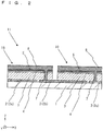
- Fig. 1 is a perspective view illustrating an example of a photoelectric conversion device according to an embodiment of the present invention and Fig. 2 is an XZ cross-sectional view thereof.
- An XYZ coordinate system of a right-handed system using the arrangement direction (the left-right direction in Fig. 1 ) of photoelectric conversion cells 10 as the X-axis direction is given to Figs. 1 and 2 .
- a photoelectric conversion device 11 a plurality of photoelectric conversion cells 10 are arranged on a substrate 1 and are electrically connected to one another. Although only two photoelectric conversion cells 10 are illustrated in Fig.
- multiple photoelectric conversion cells 10 may be two-dimensionally arranged in the right-left direction (X-axis direction), and further in a direction (Y-axis direction) perpendicular to the right-left direction in the actual photoelectric conversional device 11.
- a plurality of lower electrode layers 2 are two-dimensionally arranged on the substrate 1.
- the plurality of lower electrode layers 2 include lower electrode layers 2a to 2c arranged in one direction (X-axis direction) with a gap between them.
- a first semiconductor layer 3 is disposed over the lower electrode layer 2a and the lower electrode layer 2b through a portion on the substrate 1.
- a second semiconductor layer 4 whose conductivity type is different from that of the first semiconductor layer 3 is disposed on the first semiconductor layer 3.
- a connection conductor 7 is disposed on the lower electrode layer 2b along the surface (side surface) of the first semiconductor layer 3 or by penetrating (dividing) the first semiconductor layer 3.
- connection conductor 7 electrically connects the second semiconductor layer 4 and the lower electrode layer 2b.
- One photoelectric conversion cell 10 is formed of the lower electrode layer 2, the first semiconductor layer 3, and the second semiconductor layer 4, and a high-output photoelectric conversion device 11 is configured by connecting adjacent photoelectric conversion cells 10 in series through the connection conductor 7.
- a high-output photoelectric conversion device 11 is configured by connecting adjacent photoelectric conversion cells 10 in series through the connection conductor 7.
- the substrate 1 supports the photoelectric conversion cells 10.
- Examples of a material to be used for the substrate 1 include glass, ceramics, resins, metals, and the like.
- soda lime glass having a thickness of approximately 1 mm to 3 mm can be used.
- the lower electrode layers 2 are conductors such as Mo, Al, Ti, or Au disposed on the substrate 1.
- the lower electrode layers 2 are formed to have a thickness of approximately 0.2 ⁇ m to 1 ⁇ m using a known thin film forming method such as a sputtering method or a deposition method.
- the first semiconductor layer 3 has a thickness of, for example, 1 ⁇ m to 3 ⁇ m and mainly includes a group I-III-VI compound.
- the group I-III-VI compound is a compound of group I-B elements (also referred to as group 11 elements), group III-B elements (also referred to as group 13 elements), and a chalcogen element.
- the chalcogen element is S, Se, or Te in group VI-B elements.
- the group I-III-VI compound examples include CuInSe 2 (copper indium diselenide, also referred to as CIS), Cu(In,Ga)Se 2 (copper indium gallium diselenide, also referred to as CIGS), and Cu(In,Ga)(Se,S) 2 (copper indium gallium diselenide disulfide, also referred to as CIGSS).
- the first semiconductor layer 3 may be formed of a multiple compound semiconductor thin film such as copper indium gallium diselenide provided with a thin copper indium gallium diselenide disulfide layer as a surface layer.
- the first semiconductor layer 3 further includes an oxygen element, and the atomic concentration of the oxygen element is lower in the surface portion on the lower electrode layer 2 side than in the central portion of the first semiconductor layer 3 in the thickness direction (Z-axis direction).
- the photoelectric conversion efficiency of the photoelectric conversion device 11 is improved. That is, it is possible to sufficiently reduce recombination of carriers by filling defects of the first semiconductor layer 3 with the oxygen element, since the oxygen element is contained in the first semiconductor layer 3, and possible to effectively suppress formation of a different phase with high resistance due to oxidation of the lower electrode layer 2, since the oxygen concentration is lower in the surface portion on the lower electrode layer 2 side of the first semiconductor layer 3.
- a position of the energy in a valence band of the first semiconductor layer 3 can be shifted to a negative potential side in the vicinity of the lower electrode layer 2, since the oxygen concentration is lower in the surface portion on the lower electrode layer 2 side of the first semiconductor layer 3.
- positive holes can be sufficiently moved from the first semiconductor layer 3 to the lower electrode layer 2.
- the atomic concentration of the oxygen element in the surface portion on the lower electrode layer 2 side is lower than the atomic concentration of the oxygen element in the central portion, in a case where the first semiconductor layer 3 is assumed to be divided into the surface portion on the lower electrode layer 2 side, the central portion, and the surface portion on the second semiconductor layer 4 side by being trisected in the thickness direction (Z-axis direction).
- the atomic concentration of the oxygen element is acquired, for example, by measuring the oxygen concentration with energy dispersive X-ray spectroscopy (EDS) in the cross sections of the above-described respective trisected layers.
- EDS energy dispersive X-ray spectroscopy
- the atomic concentration of the oxygen element may be measured using secondary ion mass spectroscopy (SIMS) while the first semiconductor layer 3 is cut in the depth direction by sputtering.
- SIMS secondary ion mass spectroscopy
- the atomic concentration of the oxygen element in the central portion of the first semiconductor layer 3 may be, for example, in the range of 1x10 20 atoms/cm 3 to 1x10 22 atoms/cm 3 , and more preferably in the range of 2x10 20 atoms/cm 3 to 3x10 20 atoms/cm 3 .
- the atomic concentration of the oxygen element in the surface portion on the lower electrode layer 2 side may be 0.1 times to 0.9 times of the atomic concentration of the oxygen element in the central portion, and more preferably 0.1 times to 0.5 times thereof.
- the atomic concentration of the oxygen element in the first semiconductor layer 3 may gradually become lower toward the lower electrode layer 2 from the central portion.
- Fig. 3 illustrates an example of distribution of the atomic concentration of the oxygen element in the first semiconductor layer 3 in the thickness direction.
- the distribution of the atomic concentration of the oxygen element was measured using SIMS while the first semiconductor layer 3 was cut in the depth direction by sputtering, and the horizontal axis represents a distance from the lower electrode layer 2 and the vertical axis represents the atomic concentration of the oxygen element.
- a ratio of the atomic concentration of the gallium element to the total of the indium element and the gallium element may be larger in the surface portion on the lower electrode layer 2 side than in the central portion of the first semiconductor layer 3.
- the position of energy in a conduction band of the first semiconductor layer 3 can be shifted to the negative potential side in the vicinity of the lower electrode layer 2.
- movement of electrons from the first semiconductor layer 3 to the second semiconductor layer 4 can be improved. Accordingly, the photoelectric conversion efficiency of the photoelectric conversion device 11 is further improved.
- M Ga /(M Ga +M In ) M Ga represents the atomic concentration of the gallium element and M In represents the atomic concentration of the indium element.
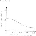
- Fig. 4 illustrates an example of the distribution of the atomic concentration ratio of the gallium element to the total of the indium element and the gallium element in the first semiconductor layer 3 in the thickness direction.
- the horizontal axis represents a distance from the lower electrode layer 2 and the vertical axis represents M Ga /(M Ga +M In ).
- the first semiconductor layer 3 whose ratio of the atomic concentration (M Ga /(M Ga +M In )) is different in the thickness direction can be produced by laminating coating films using a raw material whose ratio of concentration of the indium element to the gallium element is changed.
- the second semiconductor layer 4 is a semiconductor layer of a second conductivity type which is different from the conductivity type of the first semiconductor layer 3. By electrically connecting the first semiconductor layer 3 and the second semiconductor layer 4, a photoelectric conversion layer with which charges are extracted well is formed.
- the second semiconductor layer 4 is an n-type semiconductor layer.
- the first semiconductor layer 3 may be an n-type semiconductor layer and the second semiconductor layer 4 may be a p-type semiconductor layer.
- the second semiconductor layer 4 may be formed of a plurality of layers and at least one of the plurality of layers may be a high-resistance layer.
- Examples of materials of the second semiconductor layer 4 include CdS, ZnS, ZnO, In 2 S 3 , In 2 Se 3 , In(OH,S), (Zn,In)(Se,OH), (Zn,Mg)O, and the like.
- the second semiconductor layer 4 is formed to have a thickness of 10 nm to 200 nm using, for example, a chemical bath deposition (CBD) method or the like.
- In(OH,S) means a mixed crystal compound containing In as a hydroxide and a sulfide.
- Zn,In)(Se,OH) is a mixed crystal compound containing Zn and In as a selenide and a hydroxide.
- (Zn,Mg)O is a compound containing Zn and Mg as an oxide.
- the upper electrode layer 5 may be further disposed on the second semiconductor layer 4.
- the upper electrode layer 5 is a layer with resistivity lower than that of the second semiconductor layer 4 and with which charges generated in the first semiconductor layer 3 and the second semiconductor layer 4 can be extracted well.
- the resistivity of the upper electrode layer 5 may be lower than 1 ⁇ cm and the sheet resistance thereof may be equal to or lower than 50 ⁇ / ⁇ .
- the upper electrode layer 5 is a transparent conductive film having a thickness of 0.05 ⁇ m to 3 ⁇ m made of ITO, ZnO, or the like, for example.
- the upper electrode layer 5 may be formed of a semiconductor having the same conductivity type as that of the second semiconductor layer 4.
- the upper electrode layer 5 may be formed by a sputtering method, a evaporation method, a chemical vapor deposition (CVD) method, or the like.
- a collector electrode 8 may be further formed on the upper electrode layer 5.
- the collector electrode 8 is an electrode for further efficiently extracting charges generated in the first semiconductor layer 3 and the second semiconductor layer 4.
- the collector electrode 8 is formed, for example, linearly from one end of the photoelectric conversion cell 10 to the connection conductor 7 as illustrated in Fig. 1 . Accordingly, the current generated in the first semiconductor layer 3 and the second semiconductor layer 4 is collected in the collector electrode 8 through the upper electrode layer 5, and is efficiently passed to the adjacent photoelectric conversion cells 10 through the connection conductor 7.
- the collector electrode 8 may have a width of 50 ⁇ m to 400 ⁇ m from a viewpoint of improving light transmittance to the first semiconductor layer 3 and having good conductivity. Further, the collector electrode 8 may include a plurality of branched portions.
- the collector electrode 8 is formed by, for example, preparing a metal paste which is obtained by dispersing metal powder such as Ag powder in a resin binder or the like, printing the metal paste into a pattern shape, and curing the metal paste.
- connection conductor 7 is a conductor disposed in a groove penetrating (dividing) the first semiconductor layer 3, the second semiconductor layer 4, and the upper electrode layer 5.
- a metal, a conductive paste, or the like can be used for the connection conductor 7.
- the connection conductor 7 is formed by extending the collector electrode 8, but not limited thereto.
- the connection conductor 7 may be formed by extending the upper electrode layer 5.
- the photoelectric conversion device 11 having the above-described configuration
- the first semiconductor layer 3 is made of CIGS
- the lower electrode layer 2 which is formed of Mo or the like, is formed into a desired pattern using a sputtering method or the like on a main surface of the substrate 1 formed of glass or the like.
- a first coating film is formed by coating the lower electrode layer 2 with a film of a raw material solution formed by metal elements (Cu, In, and Ga), which constitute the group I-III-VI compound (CIGS), being dissolved in a solvent, as an organic complex or an organic acid salt. Further, in an atmosphere containing oxygen or water, the first coating film is heated at, for example, 150°C to 350°C, and consequently an organic component in the first coating film is thermally decomposed. During the thermal decomposition, part of the metal element in the first coating film is oxidized (hereinafter, a process of forming the first coating film and thermally decomposing the organic component is referred to as a first process).
- a process of forming the first coating film and thermally decomposing the organic component is referred to as a first process).
- a second coating film is formed on the thermally decomposed first coating film using the above-described raw material solution.
- the second coating film is heated in an atmosphere containing water or oxygen with a concentration higher than that of the first process, and consequently an organic component in the second coating film is thermally decomposed. Accordingly, the oxygen concentration of the second coating film is higher than that of the first coating film.
- a third coating film is formed on the thermally decomposed second coating film using the above-described raw material solution. Further, the third coating film is heated in an atmosphere containing water or oxygen, and consequently an organic component in the third coating film is thermally decomposed.
- a laminate including three layers of coating films whose oxygen concentration is lower on the lower electrode layer 2 side than in the central portion in the thickness direction is formed by the above-described process. Further, although three layers are formed herein, two or four or more layers may be formed.
- the oxygen concentration of the respective layers can be adjusted by changing the concentration of water or oxygen in an atmosphere at the time of thermal decomposition, as described above.
- the laminate with the coating films is heated at, for example, 500°C to 600°C in an atmosphere containing a chalcogen element. Accordingly, although a crystal of the group I-III-VI compound (CIGS) is generated while oxygen in the coating films is substituted with the chalcogen element, some oxygen existing in the coating films remains. Since the probability of oxygen remaining in the coating films depends on the concentration of oxygen contained in the coating films, there is a tendency that CIGS having a higher oxygen concentration is generated from the second coating film having a high oxygen concentration as compared with the first coating film. As a result, the first semiconductor layer 3 which contains CIGS and oxygen and whose atomic concentration of oxygen is lower in the surface portion on the lower electrode layer 2 side than in the central portion in the thickness direction is generated.
- CIGS group I-III-VI compound
- the second semiconductor layer 4 and the upper electrode layer 5 are sequentially formed on the first semiconductor layer 3 using a CBD method, a sputtering method, or the like.
- the first semiconductor layer 3, the second semiconductor layer 4, and the upper electrode layer 5 are processed through a mechanical scribing process or the like and consequently a groove for the connection conductor 7 is formed.
- conductive paste which is obtained by dispersing metal powder such as Ag powder in a resin binder or the like, is printed in a pattern shape on the upper electrode layer 5 and in the groove, and the collector electrode 8 and the connection conductor 7 are formed by heating and curing the printed conductive paste.
- the first semiconductor layer 3 to the collector electrode 8 are removed at a position shifted from the connection conductor 7 through a mechanical scribing process so as to provide a plurality of photoelectric conversion cells 10 being divided, thereby obtaining the photoelectric conversion device 11 illustrated in Figs. 1 and 2 .
- a raw material solution for forming a first semiconductor layer 3 was prepared.
- a solution obtained by dissolving a single source precursor which was prepared based on US Patent No. 6992202 in pyridine was used.
- the single source precursor a mixture of one in which a complex molecule is formed of Cu, In, and phenylselenol and one in which a complex molecule is formed of Cu, Ga, and phenylselenol was used.
- a substrate 1 formed of glass with the surface which is coated with a lower electrode layer 2 formed of Mo was prepared, and a first coating film was formed by coating the lower electrode layer 2 with the raw material solution using a blade method.
- the first coating film was heated at 280°C for 10 minutes and consequently the organic components contained in the first coating film were thermally decomposed.
- a second coating film was formed by coating the thermally decomposed first coating film with the raw material solution using the blade method.
- the second coating film was heated at 280°C for 10 minutes and consequently the organic components contained in the second coating film were thermally decomposed.
- a third coating film was formed by coating the thermally decomposed second coating film with the raw material solution using the blade method.
- the third coating film was heated at 280°C for 10 minutes and consequently the organic components contained in the third coating film were thermally decomposed.
- the laminate of the first coating film, the second coating film, and the third coating film was heated at 550°C for 1 hour, and consequently the first semiconductor layer 3 mainly containing CIGS and having a thickness of 2 ⁇ m was formed.
- a second semiconductor layer 4 containing In 2 S 3 and having a thickness of 50 nm was formed on the first semiconductor layer 3 by immersing the substrate, on which layers up to the first semiconductor layer 3 are formed, in an aqueous solution in which indium chloride and thioacetamide were dissolved.
- an upper electrode layer 5 formed of AZO was formed on the second semiconductor layer 4 with a sputtering method to obtain the photoelectric conversion device 11 serving as an evaluation sample.
- the distribution of the oxygen element in the first semiconductor layer 3 was measured by performing SIMS measurement while the first semiconductor layer 3 of the evaluation sample prepared as described above was etched in the thickness direction. The result is illustrated in Fig. 3 . It was understood that the oxygen concentration was lower in the surface portion on the lower electrode layer 2 side than in the central portion of the first semiconductor layer 3 in the thickness direction.
- a comparative sample was prepared.
- the comparative sample was prepared in the same manner as that of the evaluation sample except the formation of the first semiconductor layer.
- thermal decomposition of the first to third coating films was performed in an atmosphere free from water and respective layers were thermally decomposed under the same conditions. That is, in the process of thermal decomposition performed on each of the first to third coating films, respective coating films were heated at 280°C for 10 minutes in a nitrogen gas atmosphere and consequently the organic components contained in respective coating films were thermally decomposed.
- the distribution of the oxygen element in the first semiconductor layer was measured by performing SIMS measurement while the first semiconductor layer of the comparative sample prepared as described above was etched in the thickness direction. As a result, in the comparative sample, only a trace amount of the oxygen element was contained and a difference in concentration of the oxygen element in the thickness direction of the first semiconductor layer was not observed.
- the photoelectric conversion efficiency of the evaluation sample and the comparative sample prepared in the above-described manner was measured as follows.
- the photoelectric conversion efficiency was measured using a so-called stationary light solar simulator under the condition that irradiation intensity of light with respect to a light receiving surface of the photoelectric conversion device was 100 mW/cm 2 and AM (air mass) was 1.5.
- the photoelectric conversion efficiency of the evaluation sample was 12.8% while the photoelectric conversion efficiency of the comparative sample was 10.0%, and therefore, it was understood that the photoelectric conversion efficiency of the evaluation sample was higher than that of the comparative sample.
Description
- The present invention relates to a photoelectric conversion device including a group I-III-VI compound.
- As a photoelectric conversion device to be used for solar photovoltaic power generation, a device using a group I-III-VI compound such as CIGS having a high optical absorption coefficient as a light absorbing layer is exemplified. Such a photoelectric conversion device is disclosed in, for example, Japanese Unexamined Patent Application Publication No.
8-330614 - Document
WO2012/002381 discloses a CIGS solar cell, where a portion of the absorber layer has a higher oxygen content to compensate for the defects caused by the vicinity of the electrode. - The photoelectric conversion device including such a group I-III-VI compound is formed by two-dimensionally arranging a plurality of photoelectric conversion cells, in which a lower electrode layer such as a metal electrode, a light-absorbing layer, a buffer layer, and a transparent conductive film are stacked in this order on a substrate such as glass. The plurality of photoelectric conversion cells are electrically connected in series by connecting the transparent conductive film of one of the adjacent photoelectric conversion cells and the lower electrode layer of the other of the adjacent photoelectric conversion cells through a connection conductor.
- Improvement of photoelectric conversion efficiency is constantly demanded for the photoelectric conversion device including the group I-III-VI compound. The photoelectric conversion efficiency represents a ratio in which energy of solar light is converted into electric energy in the photoelectric conversion device, and is derived, for example, by dividing a value of the electric energy output from the photoelectric conversion device by a value of the energy of solar light incident to the photoelectric conversion device and then multiplying the divided value by 100.
- An object of the present invention is to improve photoelectric conversion efficiency of a photoelectric conversion device.
- A photoelectric conversion device according to an embodiment of the present invention includes an electrode layer; a first semiconductor layer disposed on the electrode layer and including a group I-III-VI compound; and a second semiconductor layer disposed on the first semiconductor layer and forming a pn junction with the first semiconductor layer. The first semiconductor layer includes at least one of sulfur, selenium, and tellurium as group VI-B elements and oxygen. In addition, an atomic concentration of oxygen in the first semiconductor layer is lower in a surface portion on the electrode layer side than in a central portion of the first semiconductor layer in a thickness direction thereof.
- According to the present invention, the photoelectric conversion efficiency in the photoelectric conversion device is improved.
-
-
Fig. 1 is a perspective view illustrating an example of a photoelectric conversion device according to an embodiment. -
Fig. 2 is a cross-sectional view of the photoelectric conversion device illustrated inFig. 1 . -
Fig. 3 is a graph illustrating distribution of oxygen concentration in a first semiconductor layer. -
Fig. 4 is a graph illustrating a ratio of a gallium element to the total of the gallium element and an indium element of a first semiconductor layer in another example of the photoelectric conversion device. - Hereinafter, a photoelectric conversion device according to an embodiment of the present invention will be described in detail with reference to the drawings.
-
Fig. 1 is a perspective view illustrating an example of a photoelectric conversion device according to an embodiment of the present invention andFig. 2 is an XZ cross-sectional view thereof. An XYZ coordinate system of a right-handed system using the arrangement direction (the left-right direction inFig. 1 ) ofphotoelectric conversion cells 10 as the X-axis direction is given toFigs. 1 and2 . In aphotoelectric conversion device 11, a plurality ofphotoelectric conversion cells 10 are arranged on asubstrate 1 and are electrically connected to one another. Although only twophotoelectric conversion cells 10 are illustrated inFig. 1 for convenience of illustration, multiplephotoelectric conversion cells 10 may be two-dimensionally arranged in the right-left direction (X-axis direction), and further in a direction (Y-axis direction) perpendicular to the right-left direction in the actual photoelectricconversional device 11. - In
Figs. 1 and2 , a plurality oflower electrode layers 2 are two-dimensionally arranged on thesubstrate 1. InFigs. 1 and2 , the plurality oflower electrode layers 2 includelower electrode layers 2a to 2c arranged in one direction (X-axis direction) with a gap between them. Afirst semiconductor layer 3 is disposed over thelower electrode layer 2a and thelower electrode layer 2b through a portion on thesubstrate 1. In addition, asecond semiconductor layer 4 whose conductivity type is different from that of thefirst semiconductor layer 3 is disposed on thefirst semiconductor layer 3. Further, aconnection conductor 7 is disposed on thelower electrode layer 2b along the surface (side surface) of thefirst semiconductor layer 3 or by penetrating (dividing) thefirst semiconductor layer 3. Theconnection conductor 7 electrically connects thesecond semiconductor layer 4 and thelower electrode layer 2b. Onephotoelectric conversion cell 10 is formed of thelower electrode layer 2, thefirst semiconductor layer 3, and thesecond semiconductor layer 4, and a high-outputphotoelectric conversion device 11 is configured by connecting adjacentphotoelectric conversion cells 10 in series through theconnection conductor 7. In addition, in thephotoelectric conversion device 11 in the present embodiment, it is assumed that light is incident from thesecond semiconductor layer 4 side, but without being limited thereto, light may be incident from thesubstrate 1 side. - The
substrate 1 supports thephotoelectric conversion cells 10. Examples of a material to be used for thesubstrate 1 include glass, ceramics, resins, metals, and the like. As thesubstrate 1, soda lime glass having a thickness of approximately 1 mm to 3 mm can be used. - The lower electrode layers 2 (
lower electrode layers substrate 1. Thelower electrode layers 2 are formed to have a thickness of approximately 0.2 µm to 1 µm using a known thin film forming method such as a sputtering method or a deposition method. - The
first semiconductor layer 3 has a thickness of, for example, 1 µm to 3 µm and mainly includes a group I-III-VI compound. The group I-III-VI compound is a compound of group I-B elements (also referred to asgroup 11 elements), group III-B elements (also referred to as group 13 elements), and a chalcogen element. Note that, the chalcogen element is S, Se, or Te in group VI-B elements. Examples of the group I-III-VI compound include CuInSe2 (copper indium diselenide, also referred to as CIS), Cu(In,Ga)Se2 (copper indium gallium diselenide, also referred to as CIGS), and Cu(In,Ga)(Se,S)2 (copper indium gallium diselenide disulfide, also referred to as CIGSS). Alternatively, thefirst semiconductor layer 3 may be formed of a multiple compound semiconductor thin film such as copper indium gallium diselenide provided with a thin copper indium gallium diselenide disulfide layer as a surface layer. - In addition, the
first semiconductor layer 3 further includes an oxygen element, and the atomic concentration of the oxygen element is lower in the surface portion on thelower electrode layer 2 side than in the central portion of thefirst semiconductor layer 3 in the thickness direction (Z-axis direction). With such a configuration, the photoelectric conversion efficiency of thephotoelectric conversion device 11 is improved. That is, it is possible to sufficiently reduce recombination of carriers by filling defects of thefirst semiconductor layer 3 with the oxygen element, since the oxygen element is contained in thefirst semiconductor layer 3, and possible to effectively suppress formation of a different phase with high resistance due to oxidation of thelower electrode layer 2, since the oxygen concentration is lower in the surface portion on thelower electrode layer 2 side of thefirst semiconductor layer 3. In addition, a position of the energy in a valence band of thefirst semiconductor layer 3 can be shifted to a negative potential side in the vicinity of thelower electrode layer 2, since the oxygen concentration is lower in the surface portion on thelower electrode layer 2 side of thefirst semiconductor layer 3. As a result, positive holes can be sufficiently moved from thefirst semiconductor layer 3 to thelower electrode layer 2. - Regarding the
first semiconductor layer 3, it is at least desired that the atomic concentration of the oxygen element in the surface portion on thelower electrode layer 2 side is lower than the atomic concentration of the oxygen element in the central portion, in a case where thefirst semiconductor layer 3 is assumed to be divided into the surface portion on thelower electrode layer 2 side, the central portion, and the surface portion on thesecond semiconductor layer 4 side by being trisected in the thickness direction (Z-axis direction). - The atomic concentration of the oxygen element is acquired, for example, by measuring the oxygen concentration with energy dispersive X-ray spectroscopy (EDS) in the cross sections of the above-described respective trisected layers. Alternatively, the atomic concentration of the oxygen element may be measured using secondary ion mass spectroscopy (SIMS) while the
first semiconductor layer 3 is cut in the depth direction by sputtering. - From a viewpoint of improving the photoelectric conversion efficiency, the atomic concentration of the oxygen element in the central portion of the
first semiconductor layer 3 may be, for example, in the range of 1x10²⁰ atoms/cm3 to 1x10²² atoms/cm3, and more preferably in the range of 2x10²⁰ atoms/cm3 to 3x10²⁰ atoms/cm3. Further, the atomic concentration of the oxygen element in the surface portion on thelower electrode layer 2 side may be 0.1 times to 0.9 times of the atomic concentration of the oxygen element in the central portion, and more preferably 0.1 times to 0.5 times thereof. - From a viewpoint of improving charge movement in the
first semiconductor layer 3, the atomic concentration of the oxygen element in thefirst semiconductor layer 3 may gradually become lower toward thelower electrode layer 2 from the central portion. For example,Fig. 3 illustrates an example of distribution of the atomic concentration of the oxygen element in thefirst semiconductor layer 3 in the thickness direction. InFig. 3 , the distribution of the atomic concentration of the oxygen element was measured using SIMS while thefirst semiconductor layer 3 was cut in the depth direction by sputtering, and the horizontal axis represents a distance from thelower electrode layer 2 and the vertical axis represents the atomic concentration of the oxygen element. - Moreover, in a case where the
first semiconductor layer 3 contains an indium element and a gallium element as in the case of CIGS or the like, a ratio of the atomic concentration of the gallium element to the total of the indium element and the gallium element (MGa/ (MGa+MIn)) may be larger in the surface portion on thelower electrode layer 2 side than in the central portion of thefirst semiconductor layer 3. In this case, the position of energy in a conduction band of thefirst semiconductor layer 3 can be shifted to the negative potential side in the vicinity of thelower electrode layer 2. As a result, movement of electrons from thefirst semiconductor layer 3 to thesecond semiconductor layer 4 can be improved. Accordingly, the photoelectric conversion efficiency of thephotoelectric conversion device 11 is further improved. Note that, in MGa/(MGa+MIn), MGa represents the atomic concentration of the gallium element and MIn represents the atomic concentration of the indium element. - In this case, when the ratio of the atomic concentration of the gallium element to the total of the indium element and the gallium element (MGa/(MGa+MIn)) gradually becomes larger toward the
lower electrode layer 2 from the central portion of thefirst semiconductor layer 3, movement of charges in thefirst semiconductor layer 3 is further improved. For example,Fig. 4 illustrates an example of the distribution of the atomic concentration ratio of the gallium element to the total of the indium element and the gallium element in thefirst semiconductor layer 3 in the thickness direction. InFig. 4 , the horizontal axis represents a distance from thelower electrode layer 2 and the vertical axis represents MGa/(MGa+MIn). - The
first semiconductor layer 3 whose ratio of the atomic concentration (MGa/(MGa+MIn)) is different in the thickness direction can be produced by laminating coating films using a raw material whose ratio of concentration of the indium element to the gallium element is changed. - The
second semiconductor layer 4 is a semiconductor layer of a second conductivity type which is different from the conductivity type of thefirst semiconductor layer 3. By electrically connecting thefirst semiconductor layer 3 and thesecond semiconductor layer 4, a photoelectric conversion layer with which charges are extracted well is formed. For example, in a case where thefirst semiconductor layer 3 is a p-type semiconductor layer, thesecond semiconductor layer 4 is an n-type semiconductor layer. Thefirst semiconductor layer 3 may be an n-type semiconductor layer and thesecond semiconductor layer 4 may be a p-type semiconductor layer. Further, thesecond semiconductor layer 4 may be formed of a plurality of layers and at least one of the plurality of layers may be a high-resistance layer. - Examples of materials of the
second semiconductor layer 4 include CdS, ZnS, ZnO, In2S3, In2Se3, In(OH,S), (Zn,In)(Se,OH), (Zn,Mg)O, and the like. Thesecond semiconductor layer 4 is formed to have a thickness of 10 nm to 200 nm using, for example, a chemical bath deposition (CBD) method or the like. In addition, In(OH,S) means a mixed crystal compound containing In as a hydroxide and a sulfide. (Zn,In)(Se,OH) is a mixed crystal compound containing Zn and In as a selenide and a hydroxide. (Zn,Mg)O is a compound containing Zn and Mg as an oxide. - As illustrated in
Figs. 1 and2 , theupper electrode layer 5 may be further disposed on thesecond semiconductor layer 4. Theupper electrode layer 5 is a layer with resistivity lower than that of thesecond semiconductor layer 4 and with which charges generated in thefirst semiconductor layer 3 and thesecond semiconductor layer 4 can be extracted well. From a viewpoint of further improving photoelectric conversion efficiency, the resistivity of theupper electrode layer 5 may be lower than 1 Ω·cm and the sheet resistance thereof may be equal to or lower than 50 Ω/□. - The
upper electrode layer 5 is a transparent conductive film having a thickness of 0.05 µm to 3 µm made of ITO, ZnO, or the like, for example. For improving translucency and conductivity, theupper electrode layer 5 may be formed of a semiconductor having the same conductivity type as that of thesecond semiconductor layer 4. Theupper electrode layer 5 may be formed by a sputtering method, a evaporation method, a chemical vapor deposition (CVD) method, or the like. - Further, as illustrated in
Figs. 1 and2 , acollector electrode 8 may be further formed on theupper electrode layer 5. Thecollector electrode 8 is an electrode for further efficiently extracting charges generated in thefirst semiconductor layer 3 and thesecond semiconductor layer 4. Thecollector electrode 8 is formed, for example, linearly from one end of thephotoelectric conversion cell 10 to theconnection conductor 7 as illustrated inFig. 1 . Accordingly, the current generated in thefirst semiconductor layer 3 and thesecond semiconductor layer 4 is collected in thecollector electrode 8 through theupper electrode layer 5, and is efficiently passed to the adjacentphotoelectric conversion cells 10 through theconnection conductor 7. - The
collector electrode 8 may have a width of 50 µm to 400 µm from a viewpoint of improving light transmittance to thefirst semiconductor layer 3 and having good conductivity. Further, thecollector electrode 8 may include a plurality of branched portions. - The
collector electrode 8 is formed by, for example, preparing a metal paste which is obtained by dispersing metal powder such as Ag powder in a resin binder or the like, printing the metal paste into a pattern shape, and curing the metal paste. - In
Figs. 1 and2 , theconnection conductor 7 is a conductor disposed in a groove penetrating (dividing) thefirst semiconductor layer 3, thesecond semiconductor layer 4, and theupper electrode layer 5. A metal, a conductive paste, or the like can be used for theconnection conductor 7. InFigs. 1 and2 , theconnection conductor 7 is formed by extending thecollector electrode 8, but not limited thereto. For example, theconnection conductor 7 may be formed by extending theupper electrode layer 5. - Next, a method for producing the
photoelectric conversion device 11 having the above-described configuration will be described. Here, a case in which thefirst semiconductor layer 3 is made of CIGS will be described. First, thelower electrode layer 2, which is formed of Mo or the like, is formed into a desired pattern using a sputtering method or the like on a main surface of thesubstrate 1 formed of glass or the like. - In addition, using a coating method or the like, a first coating film is formed by coating the
lower electrode layer 2 with a film of a raw material solution formed by metal elements (Cu, In, and Ga), which constitute the group I-III-VI compound (CIGS), being dissolved in a solvent, as an organic complex or an organic acid salt. Further, in an atmosphere containing oxygen or water, the first coating film is heated at, for example, 150°C to 350°C, and consequently an organic component in the first coating film is thermally decomposed. During the thermal decomposition, part of the metal element in the first coating film is oxidized (hereinafter, a process of forming the first coating film and thermally decomposing the organic component is referred to as a first process). - Next, a second coating film is formed on the thermally decomposed first coating film using the above-described raw material solution. In addition, the second coating film is heated in an atmosphere containing water or oxygen with a concentration higher than that of the first process, and consequently an organic component in the second coating film is thermally decomposed. Accordingly, the oxygen concentration of the second coating film is higher than that of the first coating film.
- Subsequently, a third coating film is formed on the thermally decomposed second coating film using the above-described raw material solution. Further, the third coating film is heated in an atmosphere containing water or oxygen, and consequently an organic component in the third coating film is thermally decomposed.
- A laminate including three layers of coating films whose oxygen concentration is lower on the
lower electrode layer 2 side than in the central portion in the thickness direction is formed by the above-described process. Further, although three layers are formed herein, two or four or more layers may be formed. The oxygen concentration of the respective layers can be adjusted by changing the concentration of water or oxygen in an atmosphere at the time of thermal decomposition, as described above. - Next, the laminate with the coating films is heated at, for example, 500°C to 600°C in an atmosphere containing a chalcogen element. Accordingly, although a crystal of the group I-III-VI compound (CIGS) is generated while oxygen in the coating films is substituted with the chalcogen element, some oxygen existing in the coating films remains. Since the probability of oxygen remaining in the coating films depends on the concentration of oxygen contained in the coating films, there is a tendency that CIGS having a higher oxygen concentration is generated from the second coating film having a high oxygen concentration as compared with the first coating film. As a result, the
first semiconductor layer 3 which contains CIGS and oxygen and whose atomic concentration of oxygen is lower in the surface portion on thelower electrode layer 2 side than in the central portion in the thickness direction is generated. - After the
first semiconductor layer 3 is formed, thesecond semiconductor layer 4 and theupper electrode layer 5 are sequentially formed on thefirst semiconductor layer 3 using a CBD method, a sputtering method, or the like. In addition, thefirst semiconductor layer 3, thesecond semiconductor layer 4, and theupper electrode layer 5 are processed through a mechanical scribing process or the like and consequently a groove for theconnection conductor 7 is formed. - Thereafter, for example, conductive paste, which is obtained by dispersing metal powder such as Ag powder in a resin binder or the like, is printed in a pattern shape on the
upper electrode layer 5 and in the groove, and thecollector electrode 8 and theconnection conductor 7 are formed by heating and curing the printed conductive paste. - Finally, the
first semiconductor layer 3 to thecollector electrode 8 are removed at a position shifted from theconnection conductor 7 through a mechanical scribing process so as to provide a plurality ofphotoelectric conversion cells 10 being divided, thereby obtaining thephotoelectric conversion device 11 illustrated inFigs. 1 and2 . - Note that, the present invention is not limited to the above-described embodiment, and various changes and modifications are possible without departing from the scope of the present invention.
- Next, a
photoelectric conversion device 11 according to an embodiment of the invention will be described with a specific example. - First, a raw material solution for forming a
first semiconductor layer 3 was prepared. As the raw material solution, a solution obtained by dissolving a single source precursor which was prepared based onUS Patent No. 6992202 in pyridine was used. Further, as the single source precursor, a mixture of one in which a complex molecule is formed of Cu, In, and phenylselenol and one in which a complex molecule is formed of Cu, Ga, and phenylselenol was used. - Subsequently, a
substrate 1 formed of glass with the surface which is coated with alower electrode layer 2 formed of Mo was prepared, and a first coating film was formed by coating thelower electrode layer 2 with the raw material solution using a blade method. In addition, in an atmosphere in which water (water vapor) of 140 ppmv was contained in nitrogen gas at a partial pressure ratio, the first coating film was heated at 280°C for 10 minutes and consequently the organic components contained in the first coating film were thermally decomposed. - Next, a second coating film was formed by coating the thermally decomposed first coating film with the raw material solution using the blade method. In addition, in an atmosphere in which water (water vapor) of 200 ppmv was contained in nitrogen gas at the partial pressure ratio, the second coating film was heated at 280°C for 10 minutes and consequently the organic components contained in the second coating film were thermally decomposed.
- Next, a third coating film was formed by coating the thermally decomposed second coating film with the raw material solution using the blade method. In addition, in an atmosphere in which water (water vapor) of 200 ppmv was contained in nitrogen gas at the partial pressure ratio, the third coating film was heated at 280°C for 10 minutes and consequently the organic components contained in the third coating film were thermally decomposed.
- Subsequently, in an atmosphere in which selenium vapor of 60 ppmv is contained in hydrogen gas at the partial pressure ratio, the laminate of the first coating film, the second coating film, and the third coating film was heated at 550°C for 1 hour, and consequently the
first semiconductor layer 3 mainly containing CIGS and having a thickness of 2 µm was formed. - A
second semiconductor layer 4 containing In2S3 and having a thickness of 50 nm was formed on thefirst semiconductor layer 3 by immersing the substrate, on which layers up to thefirst semiconductor layer 3 are formed, in an aqueous solution in which indium chloride and thioacetamide were dissolved. - Moreover, an
upper electrode layer 5 formed of AZO was formed on thesecond semiconductor layer 4 with a sputtering method to obtain thephotoelectric conversion device 11 serving as an evaluation sample. - The distribution of the oxygen element in the
first semiconductor layer 3 was measured by performing SIMS measurement while thefirst semiconductor layer 3 of the evaluation sample prepared as described above was etched in the thickness direction. The result is illustrated inFig. 3 . It was understood that the oxygen concentration was lower in the surface portion on thelower electrode layer 2 side than in the central portion of thefirst semiconductor layer 3 in the thickness direction. - Next, a comparative sample was prepared. The comparative sample was prepared in the same manner as that of the evaluation sample except the formation of the first semiconductor layer. In the formation of the first semiconductor layer of the comparative sample, thermal decomposition of the first to third coating films was performed in an atmosphere free from water and respective layers were thermally decomposed under the same conditions. That is, in the process of thermal decomposition performed on each of the first to third coating films, respective coating films were heated at 280°C for 10 minutes in a nitrogen gas atmosphere and consequently the organic components contained in respective coating films were thermally decomposed.
- The distribution of the oxygen element in the first semiconductor layer was measured by performing SIMS measurement while the first semiconductor layer of the comparative sample prepared as described above was etched in the thickness direction. As a result, in the comparative sample, only a trace amount of the oxygen element was contained and a difference in concentration of the oxygen element in the thickness direction of the first semiconductor layer was not observed.
- The photoelectric conversion efficiency of the evaluation sample and the comparative sample prepared in the above-described manner was measured as follows. The photoelectric conversion efficiency was measured using a so-called stationary light solar simulator under the condition that irradiation intensity of light with respect to a light receiving surface of the photoelectric conversion device was 100 mW/cm2 and AM (air mass) was 1.5. As a result, the photoelectric conversion efficiency of the evaluation sample was 12.8% while the photoelectric conversion efficiency of the comparative sample was 10.0%, and therefore, it was understood that the photoelectric conversion efficiency of the evaluation sample was higher than that of the comparative sample.
-
- 1
- SUBSTRATE
- 2, 2a, 2b, 2c
- LOWER ELECTRODE LAYER
- 3
- FIRST SEMICONDUCTOR LAYER
- 4
- SECOND SEMICONDUCTOR LAYER
- 7
- CONNECTION CONDUCTOR
- 10
- PHOTOELECTRIC CONVERSION CELL
- 11
- PHOTOELECTRIC CONVERSION DEVICE
Claims (4)
- A photoelectric conversion device, comprising:an electrode layer;a first semiconductor layer disposed on the electrode layer and including a group I-III-VI compound; anda second semiconductor layer disposed on the first semiconductor layer and forming a pn junction with the first semiconductor layer,wherein the first semiconductor layer includes at least one of sulfur, selenium, and tellurium as group VI-B elements and oxygen, andwherein an atomic concentration of oxygen in the first semiconductor layer is lower in a surface portion on the electrode layer side than in a central portion of the first semiconductor layer in a thickness direction thereof.
- The photoelectric conversion device according to claim 1, wherein the atomic concentration of oxygen in the first semiconductor layer gradually becomes lower toward the electrode layer from the central portion.
- The photoelectric conversion device according to claim 1 or 2,
wherein the first semiconductor layer includes indium and gallium as group III-B elements, and a ratio of atomic concentration of gallium to the total of indium and gallium is higher in the surface portion on the electrode layer side than in the central portion. - The photoelectric conversion device according to claim 3, wherein the ratio of atomic concentration of gallium to the total of indium and gallium gradually becomes higher toward the electrode layer from the central portion.
Priority Applications (1)
| Application Number | Priority Date | Filing Date | Title |
|---|---|---|---|
| EP16196706.2A EP3142155A1 (en) | 2012-01-27 | 2012-11-28 | Photoelectric conversion device |
Applications Claiming Priority (3)
| Application Number | Priority Date | Filing Date | Title |
|---|---|---|---|
| JP2012014958 | 2012-01-27 | ||
| JP2012166090 | 2012-07-26 | ||
| PCT/JP2012/080761 WO2013111443A1 (en) | 2012-01-27 | 2012-11-28 | Photoelectric conversion device |
Related Child Applications (2)
| Application Number | Title | Priority Date | Filing Date |
|---|---|---|---|
| EP16196706.2A Division-Into EP3142155A1 (en) | 2012-01-27 | 2012-11-28 | Photoelectric conversion device |
| EP16196706.2A Division EP3142155A1 (en) | 2012-01-27 | 2012-11-28 | Photoelectric conversion device |
Publications (3)
| Publication Number | Publication Date |
|---|---|
| EP2808903A1 EP2808903A1 (en) | 2014-12-03 |
| EP2808903A4 EP2808903A4 (en) | 2015-09-16 |
| EP2808903B1 true EP2808903B1 (en) | 2017-01-11 |
Family
ID=48873184
Family Applications (2)
| Application Number | Title | Priority Date | Filing Date |
|---|---|---|---|
| EP12866731.8A Not-in-force EP2808903B1 (en) | 2012-01-27 | 2012-11-28 | Photoelectric conversion device |
| EP16196706.2A Withdrawn EP3142155A1 (en) | 2012-01-27 | 2012-11-28 | Photoelectric conversion device |
Family Applications After (1)
| Application Number | Title | Priority Date | Filing Date |
|---|---|---|---|
| EP16196706.2A Withdrawn EP3142155A1 (en) | 2012-01-27 | 2012-11-28 | Photoelectric conversion device |
Country Status (4)
| Country | Link |
|---|---|
| US (1) | US20150000743A1 (en) |
| EP (2) | EP2808903B1 (en) |
| JP (1) | JPWO2013111443A1 (en) |
| WO (1) | WO2013111443A1 (en) |
Families Citing this family (2)
| Publication number | Priority date | Publication date | Assignee | Title |
|---|---|---|---|---|
| JP6317877B2 (en) * | 2012-10-16 | 2018-04-25 | ローム株式会社 | Photoelectric conversion device and method for manufacturing photoelectric conversion device |
| US11621273B2 (en) | 2020-05-13 | 2023-04-04 | Micron Technology, Inc. | Integrated assemblies and methods of forming integrated assemblies |
Family Cites Families (10)
| Publication number | Priority date | Publication date | Assignee | Title |
|---|---|---|---|---|
| JP3249342B2 (en) | 1995-05-29 | 2002-01-21 | 昭和シェル石油株式会社 | Heterojunction thin-film solar cell and method of manufacturing the same |
| JP3249408B2 (en) * | 1996-10-25 | 2002-01-21 | 昭和シェル石油株式会社 | Method and apparatus for manufacturing thin film light absorbing layer of thin film solar cell |
| US6310281B1 (en) * | 2000-03-16 | 2001-10-30 | Global Solar Energy, Inc. | Thin-film, flexible photovoltaic module |
| JP2002329877A (en) * | 2001-04-27 | 2002-11-15 | National Institute Of Advanced Industrial & Technology | Cu(Ga AND/OR In)Se2 THIN FILM LAYER, Cu(InGa)(S, Se)2 THIN FILM LAYER, SOLAR BATTERY AND METHOD FOR FORMING Cu(Ga AND/OR In)Se2 THIN FILM LAYER |
| JP3976626B2 (en) * | 2002-06-25 | 2007-09-19 | 松下電器産業株式会社 | Method for producing compound semiconductor thin film |
| US6992202B1 (en) | 2002-10-31 | 2006-01-31 | Ohio Aerospace Institute | Single-source precursors for ternary chalcopyrite materials, and methods of making and using the same |
| EP2485265B1 (en) * | 2009-09-29 | 2018-12-26 | Kyocera Corporation | Photoelectric conversion device |
| JP5430758B2 (en) * | 2010-05-31 | 2014-03-05 | 京セラ株式会社 | Photoelectric conversion device |
| JP5328982B2 (en) * | 2010-06-30 | 2013-10-30 | 京セラ株式会社 | Photoelectric conversion device |
| US9447489B2 (en) * | 2011-06-21 | 2016-09-20 | First Solar, Inc. | Methods of making photovoltaic devices and photovoltaic devices |
-
2012
- 2012-11-28 JP JP2013555141A patent/JPWO2013111443A1/en active Pending
- 2012-11-28 US US14/375,129 patent/US20150000743A1/en not_active Abandoned
- 2012-11-28 EP EP12866731.8A patent/EP2808903B1/en not_active Not-in-force
- 2012-11-28 WO PCT/JP2012/080761 patent/WO2013111443A1/en active Application Filing
- 2012-11-28 EP EP16196706.2A patent/EP3142155A1/en not_active Withdrawn
Non-Patent Citations (1)
| Title |
|---|
| None * |
Also Published As
| Publication number | Publication date |
|---|---|
| US20150000743A1 (en) | 2015-01-01 |
| WO2013111443A1 (en) | 2013-08-01 |
| EP2808903A4 (en) | 2015-09-16 |
| EP2808903A1 (en) | 2014-12-03 |
| EP3142155A1 (en) | 2017-03-15 |
| JPWO2013111443A1 (en) | 2015-05-11 |
Similar Documents
| Publication | Publication Date | Title |
|---|---|---|
| EP2808903B1 (en) | Photoelectric conversion device | |
| US8709860B2 (en) | Method for manufacturing photoelectric conversion device | |
| JP5623311B2 (en) | Photoelectric conversion device | |
| WO2012147427A1 (en) | Photovoltaic converter | |
| JP5451899B2 (en) | Photoelectric conversion device | |
| JP5918042B2 (en) | Method for manufacturing photoelectric conversion device | |
| JP5566335B2 (en) | Method for manufacturing photoelectric conversion device | |
| JP5570650B2 (en) | Manufacturing method of semiconductor layer and manufacturing method of photoelectric conversion device | |
| WO2014017354A1 (en) | Photoelectric converting device | |
| JP5791802B2 (en) | Method for manufacturing photoelectric conversion device | |
| JP6162592B2 (en) | Method for manufacturing photoelectric conversion device | |
| JP2014090009A (en) | Photoelectric conversion device | |
| JP2014067745A (en) | Method for manufacturing photoelectric conversion device | |
| JP5618942B2 (en) | Method for manufacturing photoelectric conversion device | |
| JP6189604B2 (en) | Photoelectric conversion device | |
| JP2013239618A (en) | Photoelectric conversion device manufacturing method | |
| JP2013012722A (en) | Photoelectric conversion device manufacturing method | |
| US20140345693A1 (en) | Photoelectric conversion device and method for producing the same | |
| WO2014115466A1 (en) | Photovoltaic device | |
| JP2018006543A (en) | Manufacturing method of photoelectric conversion module | |
| JP2015070020A (en) | Method of manufacturing photoelectric conversion device | |
| JP2015138832A (en) | Method of manufacturing semiconductor layer and method of manufacturing photoelectric conversion device | |
| JP2014187215A (en) | Photoelectric conversion device | |
| JP2012231110A (en) | Photoelectric conversion device | |
| JP2012146943A (en) | Method for manufacturing semiconductor layer and method for manufacturing photoelectric conversion device |
Legal Events
| Date | Code | Title | Description |
|---|---|---|---|
| PUAI | Public reference made under article 153(3) epc to a published international application that has entered the european phase |
Free format text: ORIGINAL CODE: 0009012 |
|
| 17P | Request for examination filed |
Effective date: 20140723 |
|
| AK | Designated contracting states |
Kind code of ref document: A1 Designated state(s): AL AT BE BG CH CY CZ DE DK EE ES FI FR GB GR HR HU IE IS IT LI LT LU LV MC MK MT NL NO PL PT RO RS SE SI SK SM TR |
|
| DAX | Request for extension of the european patent (deleted) | ||
| RA4 | Supplementary search report drawn up and despatched (corrected) |
Effective date: 20150819 |
|
| RIC1 | Information provided on ipc code assigned before grant |
Ipc: H01L 31/032 20060101ALI20150813BHEP Ipc: H01L 31/04 20140101AFI20150813BHEP |
|
| GRAP | Despatch of communication of intention to grant a patent |
Free format text: ORIGINAL CODE: EPIDOSNIGR1 |
|
| INTG | Intention to grant announced |
Effective date: 20160628 |
|
| GRAS | Grant fee paid |
Free format text: ORIGINAL CODE: EPIDOSNIGR3 |
|
| GRAA | (expected) grant |
Free format text: ORIGINAL CODE: 0009210 |
|
| AK | Designated contracting states |
Kind code of ref document: B1 Designated state(s): AL AT BE BG CH CY CZ DE DK EE ES FI FR GB GR HR HU IE IS IT LI LT LU LV MC MK MT NL NO PL PT RO RS SE SI SK SM TR |
|
| REG | Reference to a national code |
Ref country code: GB Ref legal event code: FG4D |
|
| REG | Reference to a national code |
Ref country code: CH Ref legal event code: EP |
|
| REG | Reference to a national code |
Ref country code: AT Ref legal event code: REF Ref document number: 861980 Country of ref document: AT Kind code of ref document: T Effective date: 20170115 |
|
| REG | Reference to a national code |
Ref country code: IE Ref legal event code: FG4D |
|
| REG | Reference to a national code |
Ref country code: DE Ref legal event code: R096 Ref document number: 602012027875 Country of ref document: DE |
|
| REG | Reference to a national code |
Ref country code: LT Ref legal event code: MG4D |
|
| REG | Reference to a national code |
Ref country code: NL Ref legal event code: MP Effective date: 20170111 |
|
| REG | Reference to a national code |
Ref country code: AT Ref legal event code: MK05 Ref document number: 861980 Country of ref document: AT Kind code of ref document: T Effective date: 20170111 |
|
| PG25 | Lapsed in a contracting state [announced via postgrant information from national office to epo] |
Ref country code: NL Free format text: LAPSE BECAUSE OF FAILURE TO SUBMIT A TRANSLATION OF THE DESCRIPTION OR TO PAY THE FEE WITHIN THE PRESCRIBED TIME-LIMIT Effective date: 20170111 |
|
| PG25 | Lapsed in a contracting state [announced via postgrant information from national office to epo] |
Ref country code: NO Free format text: LAPSE BECAUSE OF FAILURE TO SUBMIT A TRANSLATION OF THE DESCRIPTION OR TO PAY THE FEE WITHIN THE PRESCRIBED TIME-LIMIT Effective date: 20170411 Ref country code: LT Free format text: LAPSE BECAUSE OF FAILURE TO SUBMIT A TRANSLATION OF THE DESCRIPTION OR TO PAY THE FEE WITHIN THE PRESCRIBED TIME-LIMIT Effective date: 20170111 Ref country code: IS Free format text: LAPSE BECAUSE OF FAILURE TO SUBMIT A TRANSLATION OF THE DESCRIPTION OR TO PAY THE FEE WITHIN THE PRESCRIBED TIME-LIMIT Effective date: 20170511 Ref country code: FI Free format text: LAPSE BECAUSE OF FAILURE TO SUBMIT A TRANSLATION OF THE DESCRIPTION OR TO PAY THE FEE WITHIN THE PRESCRIBED TIME-LIMIT Effective date: 20170111 Ref country code: HR Free format text: LAPSE BECAUSE OF FAILURE TO SUBMIT A TRANSLATION OF THE DESCRIPTION OR TO PAY THE FEE WITHIN THE PRESCRIBED TIME-LIMIT Effective date: 20170111 Ref country code: GR Free format text: LAPSE BECAUSE OF FAILURE TO SUBMIT A TRANSLATION OF THE DESCRIPTION OR TO PAY THE FEE WITHIN THE PRESCRIBED TIME-LIMIT Effective date: 20170412 |
|
| PG25 | Lapsed in a contracting state [announced via postgrant information from national office to epo] |
Ref country code: BG Free format text: LAPSE BECAUSE OF FAILURE TO SUBMIT A TRANSLATION OF THE DESCRIPTION OR TO PAY THE FEE WITHIN THE PRESCRIBED TIME-LIMIT Effective date: 20170411 Ref country code: SE Free format text: LAPSE BECAUSE OF FAILURE TO SUBMIT A TRANSLATION OF THE DESCRIPTION OR TO PAY THE FEE WITHIN THE PRESCRIBED TIME-LIMIT Effective date: 20170111 Ref country code: ES Free format text: LAPSE BECAUSE OF FAILURE TO SUBMIT A TRANSLATION OF THE DESCRIPTION OR TO PAY THE FEE WITHIN THE PRESCRIBED TIME-LIMIT Effective date: 20170111 Ref country code: PT Free format text: LAPSE BECAUSE OF FAILURE TO SUBMIT A TRANSLATION OF THE DESCRIPTION OR TO PAY THE FEE WITHIN THE PRESCRIBED TIME-LIMIT Effective date: 20170511 Ref country code: AT Free format text: LAPSE BECAUSE OF FAILURE TO SUBMIT A TRANSLATION OF THE DESCRIPTION OR TO PAY THE FEE WITHIN THE PRESCRIBED TIME-LIMIT Effective date: 20170111 Ref country code: RS Free format text: LAPSE BECAUSE OF FAILURE TO SUBMIT A TRANSLATION OF THE DESCRIPTION OR TO PAY THE FEE WITHIN THE PRESCRIBED TIME-LIMIT Effective date: 20170111 Ref country code: LV Free format text: LAPSE BECAUSE OF FAILURE TO SUBMIT A TRANSLATION OF THE DESCRIPTION OR TO PAY THE FEE WITHIN THE PRESCRIBED TIME-LIMIT Effective date: 20170111 Ref country code: PL Free format text: LAPSE BECAUSE OF FAILURE TO SUBMIT A TRANSLATION OF THE DESCRIPTION OR TO PAY THE FEE WITHIN THE PRESCRIBED TIME-LIMIT Effective date: 20170111 |
|
| REG | Reference to a national code |
Ref country code: DE Ref legal event code: R097 Ref document number: 602012027875 Country of ref document: DE |
|
| PG25 | Lapsed in a contracting state [announced via postgrant information from national office to epo] |
Ref country code: EE Free format text: LAPSE BECAUSE OF FAILURE TO SUBMIT A TRANSLATION OF THE DESCRIPTION OR TO PAY THE FEE WITHIN THE PRESCRIBED TIME-LIMIT Effective date: 20170111 Ref country code: RO Free format text: LAPSE BECAUSE OF FAILURE TO SUBMIT A TRANSLATION OF THE DESCRIPTION OR TO PAY THE FEE WITHIN THE PRESCRIBED TIME-LIMIT Effective date: 20170111 Ref country code: IT Free format text: LAPSE BECAUSE OF FAILURE TO SUBMIT A TRANSLATION OF THE DESCRIPTION OR TO PAY THE FEE WITHIN THE PRESCRIBED TIME-LIMIT Effective date: 20170111 Ref country code: SK Free format text: LAPSE BECAUSE OF FAILURE TO SUBMIT A TRANSLATION OF THE DESCRIPTION OR TO PAY THE FEE WITHIN THE PRESCRIBED TIME-LIMIT Effective date: 20170111 Ref country code: CZ Free format text: LAPSE BECAUSE OF FAILURE TO SUBMIT A TRANSLATION OF THE DESCRIPTION OR TO PAY THE FEE WITHIN THE PRESCRIBED TIME-LIMIT Effective date: 20170111 |
|
| PLBE | No opposition filed within time limit |
Free format text: ORIGINAL CODE: 0009261 |
|
| STAA | Information on the status of an ep patent application or granted ep patent |
Free format text: STATUS: NO OPPOSITION FILED WITHIN TIME LIMIT |
|
| PG25 | Lapsed in a contracting state [announced via postgrant information from national office to epo] |
Ref country code: DK Free format text: LAPSE BECAUSE OF FAILURE TO SUBMIT A TRANSLATION OF THE DESCRIPTION OR TO PAY THE FEE WITHIN THE PRESCRIBED TIME-LIMIT Effective date: 20170111 Ref country code: SM Free format text: LAPSE BECAUSE OF FAILURE TO SUBMIT A TRANSLATION OF THE DESCRIPTION OR TO PAY THE FEE WITHIN THE PRESCRIBED TIME-LIMIT Effective date: 20170111 |
|
| 26N | No opposition filed |
Effective date: 20171012 |
|
| PG25 | Lapsed in a contracting state [announced via postgrant information from national office to epo] |
Ref country code: SI Free format text: LAPSE BECAUSE OF FAILURE TO SUBMIT A TRANSLATION OF THE DESCRIPTION OR TO PAY THE FEE WITHIN THE PRESCRIBED TIME-LIMIT Effective date: 20170111 |
|
| PG25 | Lapsed in a contracting state [announced via postgrant information from national office to epo] |
Ref country code: MC Free format text: LAPSE BECAUSE OF FAILURE TO SUBMIT A TRANSLATION OF THE DESCRIPTION OR TO PAY THE FEE WITHIN THE PRESCRIBED TIME-LIMIT Effective date: 20170111 |
|
| GBPC | Gb: european patent ceased through non-payment of renewal fee |
Effective date: 20171128 |
|
| PG25 | Lapsed in a contracting state [announced via postgrant information from national office to epo] |
Ref country code: CH Free format text: LAPSE BECAUSE OF NON-PAYMENT OF DUE FEES Effective date: 20171130 Ref country code: LI Free format text: LAPSE BECAUSE OF NON-PAYMENT OF DUE FEES Effective date: 20171130 |
|
| PG25 | Lapsed in a contracting state [announced via postgrant information from national office to epo] |
Ref country code: LU Free format text: LAPSE BECAUSE OF NON-PAYMENT OF DUE FEES Effective date: 20171128 |
|
| REG | Reference to a national code |
Ref country code: FR Ref legal event code: ST Effective date: 20180731 Ref country code: BE Ref legal event code: MM Effective date: 20171130 |
|
| REG | Reference to a national code |
Ref country code: IE Ref legal event code: MM4A |
|
| PG25 | Lapsed in a contracting state [announced via postgrant information from national office to epo] |
Ref country code: MT Free format text: LAPSE BECAUSE OF NON-PAYMENT OF DUE FEES Effective date: 20171128 |
|
| PG25 | Lapsed in a contracting state [announced via postgrant information from national office to epo] |
Ref country code: IE Free format text: LAPSE BECAUSE OF NON-PAYMENT OF DUE FEES Effective date: 20171128 Ref country code: FR Free format text: LAPSE BECAUSE OF NON-PAYMENT OF DUE FEES Effective date: 20171130 |
|
| PG25 | Lapsed in a contracting state [announced via postgrant information from national office to epo] |
Ref country code: GB Free format text: LAPSE BECAUSE OF NON-PAYMENT OF DUE FEES Effective date: 20171128 Ref country code: BE Free format text: LAPSE BECAUSE OF NON-PAYMENT OF DUE FEES Effective date: 20171130 |
|
| PGFP | Annual fee paid to national office [announced via postgrant information from national office to epo] |
Ref country code: DE Payment date: 20181113 Year of fee payment: 7 |
|
| PG25 | Lapsed in a contracting state [announced via postgrant information from national office to epo] |
Ref country code: HU Free format text: LAPSE BECAUSE OF FAILURE TO SUBMIT A TRANSLATION OF THE DESCRIPTION OR TO PAY THE FEE WITHIN THE PRESCRIBED TIME-LIMIT; INVALID AB INITIO Effective date: 20121128 |
|
| PG25 | Lapsed in a contracting state [announced via postgrant information from national office to epo] |
Ref country code: CY Free format text: LAPSE BECAUSE OF FAILURE TO SUBMIT A TRANSLATION OF THE DESCRIPTION OR TO PAY THE FEE WITHIN THE PRESCRIBED TIME-LIMIT Effective date: 20170111 |
|
| PG25 | Lapsed in a contracting state [announced via postgrant information from national office to epo] |
Ref country code: MK Free format text: LAPSE BECAUSE OF FAILURE TO SUBMIT A TRANSLATION OF THE DESCRIPTION OR TO PAY THE FEE WITHIN THE PRESCRIBED TIME-LIMIT Effective date: 20170111 |
|
| PG25 | Lapsed in a contracting state [announced via postgrant information from national office to epo] |
Ref country code: TR Free format text: LAPSE BECAUSE OF FAILURE TO SUBMIT A TRANSLATION OF THE DESCRIPTION OR TO PAY THE FEE WITHIN THE PRESCRIBED TIME-LIMIT Effective date: 20170111 |
|
| REG | Reference to a national code |
Ref country code: DE Ref legal event code: R119 Ref document number: 602012027875 Country of ref document: DE |
|
| PG25 | Lapsed in a contracting state [announced via postgrant information from national office to epo] |
Ref country code: AL Free format text: LAPSE BECAUSE OF FAILURE TO SUBMIT A TRANSLATION OF THE DESCRIPTION OR TO PAY THE FEE WITHIN THE PRESCRIBED TIME-LIMIT Effective date: 20170111 |
|
| PG25 | Lapsed in a contracting state [announced via postgrant information from national office to epo] |
Ref country code: DE Free format text: LAPSE BECAUSE OF NON-PAYMENT OF DUE FEES Effective date: 20200603 |