EP2808678B2 - Getränkeabgabesystem und Verfahren - Google Patents
Getränkeabgabesystem und Verfahren Download PDFInfo
- Publication number
- EP2808678B2 EP2808678B2 EP14155354.5A EP14155354A EP2808678B2 EP 2808678 B2 EP2808678 B2 EP 2808678B2 EP 14155354 A EP14155354 A EP 14155354A EP 2808678 B2 EP2808678 B2 EP 2808678B2
- Authority
- EP
- European Patent Office
- Prior art keywords
- beverage
- line
- cooling
- connector
- cooler
- Prior art date
- Legal status (The legal status is an assumption and is not a legal conclusion. Google has not performed a legal analysis and makes no representation as to the accuracy of the status listed.)
- Active
Links
Images


Classifications
-
- B—PERFORMING OPERATIONS; TRANSPORTING
- B67—OPENING, CLOSING OR CLEANING BOTTLES, JARS OR SIMILAR CONTAINERS; LIQUID HANDLING
- B67D—DISPENSING, DELIVERING OR TRANSFERRING LIQUIDS, NOT OTHERWISE PROVIDED FOR
- B67D1/00—Apparatus or devices for dispensing beverages on draught
- B67D1/08—Details
- B67D1/12—Flow or pressure control devices or systems, e.g. valves, gas pressure control, level control in storage containers
- B67D1/1247—Means for detecting the presence or absence of liquid
-
- B—PERFORMING OPERATIONS; TRANSPORTING
- B67—OPENING, CLOSING OR CLEANING BOTTLES, JARS OR SIMILAR CONTAINERS; LIQUID HANDLING
- B67D—DISPENSING, DELIVERING OR TRANSFERRING LIQUIDS, NOT OTHERWISE PROVIDED FOR
- B67D1/00—Apparatus or devices for dispensing beverages on draught
- B67D1/08—Details
- B67D1/0829—Keg connection means
-
- B—PERFORMING OPERATIONS; TRANSPORTING
- B67—OPENING, CLOSING OR CLEANING BOTTLES, JARS OR SIMILAR CONTAINERS; LIQUID HANDLING
- B67D—DISPENSING, DELIVERING OR TRANSFERRING LIQUIDS, NOT OTHERWISE PROVIDED FOR
- B67D1/00—Apparatus or devices for dispensing beverages on draught
- B67D1/08—Details
- B67D1/0857—Cooling arrangements
Definitions
- the present invention relates to beverage dispense systems.
- the present invention relates to beverage dispense systems for dispensing beverages such as lager or cider at a low temperature.
- beverage including beers, lagers and ciders are beneficially served at low temperatures. If the temperature of the beverage is too high, the quality and the taste of the beverage may be impaired. In addition, recent consumer trends have increased the demand for beverages to be served at a lower temperature, for example, below 3°C. In order to meet consumer expectations, it is desirable to dispense beverages at a consistent low temperature.
- draught beverages beverages which are stored at a point remote from the point of dispensing and transferred on demand to the point of dispensing through a beverage line.
- the transfer is achieved using a pumping mechanism.
- a pumping mechanism For instance, it is common in public houses and bars for beverages to be stored in a cooled cellar or a storage room (typically cooled to a temperature of around 12°C using a cooling unit) and transferred to the bar area where dispensing occurs at a font using a mechanical pump or a pressurised gas system.
- the length of the beverage line between the cellar/storage room and the dispensing site may be many metres (e.g. up to 30m) and there is a tendency for beverage in the beverage lines to increase in temperature during transit.
- a cooler in or near the cellar/storage room to cool the beverage and then to transport the beverage to the dispensing site inside an insulated and cooled conduit known as a "python".
- the cooler typically comprises an ice bank and a water bath, the water in the water bath being cooled by the ice bank.
- the beverage line passes from the cellar/storage room through the water bath and beverage contained in the beverage line is thus cooled.
- the cooled beverage then flows through the python to the dispensing site, the python also carrying a cooling circuit through which cold water from the water bath is circulated. It is also known to use a glycol cooling medium in the cooler and cooling circuit to effect even greater cooling for beverages which are intended to be served "extra cold".
- Draught beverages such as lagers and ciders are typically stored within storage kegs inside the cooled cellar/storage room.
- the beverage line portion extending between a storage keg and the cooler typically passes through a fob detector having a float within a chamber.
- the float sinks to the base of the chamber and seals off the beverage line.
- the user is then required to leave the dispensing site and proceed to the cellar/storage room to disconnect the empty storage keg from the beverage line and connect a new storage keg.
- the change over between storage kegs typically requires bleeding of the beverage from a valve at the top of the fob detector in order to raise the float within the chamber.
- the present inventors have identified a number of problems associated with known beverage systems.
- a temperature of 12°C i.e. the typical temperature of the cellar/storage room and thus the typical temperature of the beverage in the storage keg, fob detector and beverage line portion extending between the storage keg and the cooler
- Cooling the cellar/storage room to a lower temperature in an attempt to reduce microorganism growth is not ideal because of the extra energy that this will consume and also because many public houses/bars also store cask ales in their cellar/storage room and the quality of these cask ales will be impaired by lower temperatures.
- WO2010/019035 discloses a tapping head or keg connector having a cooling chamber provided with cooling medium to cool the tapping head and beer flowing through the tapping head.
- DE102006026025A1 discloses a keg connector having an optical sensor for detecting changes in the degree of reflectance of a liquid in order to determine gas concentration.
- the present invention aims to reduce microorganism growth within a beverage dispense system and thus reduce beverage wastage.
- the cooler is adapted to generate cooling medium for transportation within the first and/or second cooling line.
- the cooler typically comprises an ice bank and a cooling medium reservoir, the cooling medium in the cooling medium reservoir being cooled by the ice bank.
- cooler that both cools the beverage and generates the cooling medium for transportation in the cooling line(s)
- energy savings can be made.
- the cooler could be a flash cooler and the system could comprise a separate cooling medium generator to generate cooling medium for transportation within the cooling line(s).
- the beverage line preferably includes a cooling beverage line portion that passes through the cooling medium reservoir in the cooler from the first beverage line portion to the second beverage line portion.
- the cooling beverage line portion is a coiled portion that can be immersed in the cooling medium in the reservoir. The amount of coil immersed can be varied to determine the extent of heat exchange and hence the extent of cooling of the beverage.
- the first cooling line preferably forms part of a first cooling circuit, the first cooling circuit including the first cooling line extending from the cooler or the cooling medium generator through the first insulated carrier to the beverage supply and a first return line extending from the beverage supply through the first insulated carrier to the cooling medium reservoir or generator.
- the first cooling line and first return line typically have a diameter of between 9.5mm and 15mm.
- At least a portion of the first insulated carrier is preferably of the type known as a "python" which comprises a tubular sleeve formed of insulating plastics material.
- the first cooling line and the first return line preferably pass through the first python close to its axial centre with the first beverage line portion running co-axially with the first cooling/return lines.
- the second cooling line preferably forms part of a second cooling circuit, the second cooling circuit including the second cooling line extending from the cooler or the cooling medium generator through the second insulated carrier to the dispensing site and a second return line extending from the dispensing site through the second insulated carrier to the cooling medium reservoir or generator.
- the second cooling line and second return line typically have a diameter of 15mm.
- the second cooling circuit preferably includes a font cooling circuit for carrying cooling medium into the dispense font to allow heat exchange with the second beverage line portion 10 within the font to maintain the low temperature of the beverage and, optionally, to promote formation of condensation on the outer surface of the font (for aesthetic reasons).
- the lines in the font cooling circuit typically have a diameter of around 9.5mm (3/8 inch).
- the system preferably includes a second insulated carrier of the type known as a "python" which comprises a tubular sleeve formed of insulating plastics material.
- the length of second insulated carrier is unlimited but, typically, will be between 3 and 30 metres. A length of around 30 metres is most typical.
- the second cooling line and the second return line preferably pass through the second insulated carrier (python) close to its axial centre with one or more second beverage line portions running co-axially with the second cooling/return lines.
- the cooler is preferably a remote cooler i.e. it is remote from the dispensing site.
- the beverage may be transferred from the beverage supply to the dispensing site using a pressurized gas system.
- the beverage dispense system of the first aspect comprises a gas line connectable to a gas supply wherein the gas supply line is at least partly enclosed within the first insulated carrier.
- Preferred embodiments of the beverage dispense system comprise a manifold through which the first beverage line portion passes.
- the manifold comprises an insulated core e.g. a foam core which forms part of the first insulated carrier.
- the first insulated carrier may comprise a distal first insulated carrier portion (e.g. a python-type carrier) between the distal end of the first beverage line portion and the manifold, the manifold, and a proximal first insulated carrier portion(e.g. a further python-type carrier) between the manifold and the cooler.
- the beverage dispense system is for dispensing a plurality of beverages.
- the beverage dispense system comprises a plurality of beverage lines each having a respective distal end connectable to a respective beverage supply for transporting beverage from the respective beverage supply to a respective dispense font at the dispensing site.
- Each beverage line comprises a respective first beverage line portion extending from the respective distal end to the cooler.
- Each beverage line portion may extend to the cooler within a respective first insulated carrier i.e. the system comprises a plurality of first insulated carriers, each first insulated carrier comprising a respective first cooling line in heat exchange relationship with the respective first beverage line portion.
- the beverage dispense system comprises a manifold and each beverage line portion extends from its distal end to the manifold in a respective distal first insulated carrier portion (preferably of the python-type) but thereafter, up to the cooler, the beverage lines are bundled together in the insulating core of the manifold and then in a single proximal first insulated carrier portion (preferably a further python-type insulated carrier) from the manifold to the cooler.
- the beverage system is for dispensing two or four beverages and thus comprises two or four beverage lines each within its own distal first insulated carrier portion.
- the beverage supply i.e. storage kegs
- the beverage supply can be stored at the dispensing site.
- the beverage system is for dispensing eight or ten beverages and thus comprises eight or ten beverage lines each within its own distal first insulated carrier portion.
- all of the second beverage line portions for transporting beverage from the cooler to the dispensing site are preferably bundled together within a single second insulated carrier, all of the second beverage line portions being in heat exchange relationship with the second cooling line.
- the length of the first beverage line portion between the distal end and the manifold is selected such that, when the manifold is mounted on the wall or ceiling of the beverage supply site (i.e. where the beverage supply is stored), the distal end of the beverage line does not contact the floor of the beverage supply site.
- known dispense system include fob detectors typically comprising a reservoir of beverage within a chamber, the beverage sitting at the ambient temperature of the cellar i.e. around 12°C. This provides a reservoir in which microorganism growth can occur.
- the present invention preferably avoids the use of traditional fob detectors.
- the beverage dispense system comprises a connector affixed to the distal end of the beverage line for connecting the beverage line to a beverage supply, the connector comprising a sensor for sensing bubbles within the beverage line and for generating a signal for closing the beverage line when a predetermined level of bubbles is detected.
- Bubbles within a beverage can be an early indication that fobbing is about to commence and thus that the beverage supply is nearly depleted (i.e. the storage keg is nearly empty).
- a sensor which sends a signal e.g. to a valve such as a solenoid valve, when a predetermined level of bubbles (which predetermined level may be as low as a single bubble) is detected in the beverage line, the use of traditional fob detectors (and the associated problems therewith) can be avoided.
- the connector may be directly connectable to the beverage supply but, preferably, the connector is connectable e.g. by a push- or screw-fit to a standard keg coupler (i.e. a coupler which connects to the top of the keg spear and which has a gas line inlet and a beverage outlet).
- the sensor may be an optical sensor having an optical transmitter and an optical receiver. A suitable sensor is described in GB2236180 .
- the beverage line has a distal end (proximal the beverage supply and remote from the point of dispense) and the connector is affixed at the distal end of the beverage line (with the beverage line passing through the connector).
- the senor By providing the sensor in a connector at the distal end of the beverage line, the sensor can be positioned as close to the beverage supply as possible such that the bubbles preceding fobbing (which is indicative of the impending emptying of the storage keg) can be detected at the earliest possible moment.
- the connector contains cooling means for cooling the beverage line within the connector. In this way (unlike traditional fob detectors), any beverage can be maintained at temperature at which microorganism growth is limited.
- the cooling means comprises a connector cooling circuit comprising a connector cooling line and a connector cooling return line for carrying chilled cooling medium, the cooling lines being in heat exchange relationship with the beverage line.
- the connector further comprises an indicator for providing an indication when the sensor has generated a signal for closing the beverage line.
- the indicator is preferably a visible indicator e.g. a light, which may come on, go out or change colour when the beverage line is closed.
- the indicator is useful especially in beverage dispense systems where there are a plurality of beverage supplies each with a connector.
- the indicators identify to the user which beverage supply is depleted and which storage keg requires changing.
- the connector further comprises a re-set actuator e.g. button or switch which is operable to generate a signal to re-open the beverage line once the beverage supply has been replenished (i.e. the storage keg changed).
- a re-set actuator e.g. button or switch which is operable to generate a signal to re-open the beverage line once the beverage supply has been replenished (i.e. the storage keg changed).
- the re-set actuator is also preferably operable to re-set the indicator (e.g. turn the light on, off or change its colour).
- a first mode of actuation of the re-set actuator causes the beverage line to be opened to a bleed line for a predetermined amount of time thus discharging any fob in the beverage prior to reconnection of the beverage line.
- the first mode of actuation is preferably a single short actuation (e.g. depression) of the re-set actuator e.g. a single short depression of a button.
- the valve closes the bleed line and re-establishes fluid communication along the length of the beverage line.
- the bleed line can be directed to a drain or to a container thus avoiding cellar contamination.
- the indicator for providing an indication when the valve is closed may be provided on the connector as discussed above. However, if the valve is remote from the connector, there may be an additional or an alternative indicator adjacent the valve. In most preferred embodiments, if the valve is remote from the connector, two indicators are provided, one on the connector and one adjacent the valve.
- the indicator(s) is/are useful especially in dispense systems where there are a plurality of beverage supplies each with a respective bubble detection system.
- the indicators identify to the user which beverage supply is depleted and which storage keg requires changing.
- the re-set actuator e.g. button or switch which is operable to re-open the valve once the beverage supply has been replenished (i.e. the storage keg changed) and/or operable to re-set the indicator(s), is provided on the connector as discussed above. In cases where the valve is remote from the connector, there may be an additional re-set actuator adjacent the valve.
- the first mode of actuation of the re-set actuator causes beverage contained in the beverage line between the beverage supply and the valve to be discharged to a bleed line for a predetermined amount of time.
- the valve is preferably a two-way valve that can direct beverage from the beverage line either towards the dispensing site or to the bleed line. In this manner, upon the first mode of actuation of the re-set actuator, the valve opens to the bleed line.
- the first mode of actuation is preferably a single short actuation (e.g. depression) of the re-set actuator e.g. a single short depression of a button.
- the valve closes the bleed line and re-establishes fluid communication along the length of the beverage line.
- the bleed line can be directed to a drain or to a container thus avoiding cellar contamination.
- a second mode of actuation of the re-set actuator preferably initiates a cleaning function.
- the second mode of actuation is preferably a single long actuation (e.g. depression) of the re-set actuator e.g. a prolonged depression of a button but it may also be a plurality of short actuations.
- the second mode of actuation of the re-set actuation is only effected when a water or cleaning fluid supply is attached to the distal end of the beverage line.
- the second mode of actuation of the re-set actuator causes the valve to open the beverage line and for the water/cleaning fluid to be pumped through the beverage line to effect cleaning. This need only be effected once every 4 weeks.
- the bubble detection system preferably comprises an electronic control unit for receiving the signal from the sensor and, in response to the signal from the sensor, sending a signal to the valve to close the beverage line.
- the signal between the sensor and the electronic control unit may be transmitted via a wire.
- the electronic control unit also sends a signal to activate the indicator(s) upon receipt of a signal from the sensor.
- the signal between the electronic control unit and the indicator(s) may be transmitted via a wire.
- the electronic control unit also sends a signal to the valve to open to the bleed line upon receipt of a signal from the re-set actuator in the first mode of actuation and to reconnect the beverage line upon receipt of a signal from the re-set actuator in the second mode of actuation. It preferably also sends a signal to re-set the indicator(s) upon actuation of the re-set actuator.
- the signal between the re-set actuator and the electronic control unit may be transmitted via a wire.
- the bubble detection system further comprises a manifold housing the valve.
- the indicator/re-set actuator is preferably mounted on or extends from within the manifold.
- the manifold preferably further houses the electronic control unit.
- the manifold is remote from the connector e.g. it may be affixable to a wall or the ceiling of the beverage supply site (cellar/storage room). In this way, the beverage supply site can be kept clear to allow easy access to the storage kegs.
- wires between the electronic control unit and a) the sensor, b) any connector indicator and c) any connector re-set actuator will run, preferably in a bundle, from the connector to the manifold.
- the manifold preferably comprises an insulating core e.g. a foam core through which the beverage lines pass.
- This insulating core helps maintain the temperature of the beverage as it passes through the manifold.
- the connector cooling circuit is connected to the first cooling circuit, with the connector cooling line being an extension of the first cooling line and the connector cooling return line extending to the first cooling return line.
- the manifold is preferably positioned between the connector and the cooler e.g. approximately equidistant between the two.
- the first insulated carrier comprises a distal first insulated carrier portion extending from the connector to the manifold and a proximal first insulated carrier portion extending between the manifold and the cooler.
- the manifold preferably comprises an insulating core e.g. a foam core through which the beverage lines and the first cooling circuit pass. This insulating core forms part of the first insulated carrier and helps maintain the beverage at a low enough temperature to limit microorganism growth as it passes through the manifold.
- the wires between the electronic control unit and a) the sensor, b) any connector indicator, and c) any connector re-set actuator preferably run from the connector to the manifold within the distal first insulated carrier portion.
- the length of beverage line between the distal end and the manifold is selected such that, when the manifold is mounted on the wall or ceiling of the beverage supply site, the distal end of the beverage line does not contact the floor of the beverage supply site.
- the manifold may be mounted directly onto the wall or ceiling of the beverage supply site but, preferably, the manifold is mounted onto brackets affixed to the wall or ceiling of the beverage supply site.
- the brackets may be such that the manifold is suspended from the ceiling.
- a first cooling line 9 for transporting cooling medium (generated by the cooler 6) through the proximal first insulated carrier portion (a python-type insulated carrier 20), the core 33 of the manifold 19 and then through the two distal first insulated carrier portions 8, 8' is provided so as to allow heat exchange between the cooling medium in the first cooling line 9 and the beverage in the first beverage line portions 7, 7'.
- the beverage lines 2, 2' further comprise a respective second beverage line portion 10, 10' for transporting beverage from the cooler 6 to the respective tap 12, 12' on the respective dispense font 13, 13' at the dispensing site 5 through a second insulated carrier 11.
- the second insulated carrier 11 comprises a second cooling line 14 for transporting cooling medium (from the cooler 6) through the second insulated carrier 11 so as to allow heat exchange between the cooling medium in the second cooling line 14 and the beverage in the second beverage line portions 10, 10'.
- the second cooling circuit also includes a font cooling circuits 42, 42' which carry cooling medium into the font to allow heat exchange with the second beverage line portion 10 in the font to maintain the low temperature of the beverage and, optionally, to promote formation of condensation on the outer surface of the font (for aesthetic reasons).
- the lines in the font cooling circuit typically have a diameter of around 9.5mm (3/8 inch).
- Each beverage line 2, 2' includes a respective cooling beverage line portion 15, 15' that passes through the cooling medium reservoir in the cooler 6 from the first beverage line portion 7, 7' to the respective second beverage line portion 10, 10'.
- Each cooling beverage line portion 15, 15' is a coiled portion that can be immersed in the cooling medium in the reservoir. The amount of coil immersed can be varied to determine the extent of heat exchange and hence the extent of cooling of the beverage.
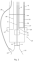
- a connector which is connected to a standard keg coupler 22 is shown in Figure 2 .
- the connector 18 includes a sensor 21 for sensing bubbles within the beverage line 2 and for generating a signal for closing the beverage line (using a solenoid valve - shown in Figure 3 ) when a predetermined level of bubbles (e.g. a single bubble) is detected.
- a sensor 21 for sensing bubbles within the beverage line 2 and for generating a signal for closing the beverage line (using a solenoid valve - shown in Figure 3 ) when a predetermined level of bubbles (e.g. a single bubble) is detected.
- the sensor is an optical sensor having an optical transmitter and an optical receiver as described in GB2236180 .
- the connector contains a connector cooling circuit 25 comprising a connector cooling line 29 for receiving cooling medium from the first cooling line 9 and a connector cooling return line 26 for returning cooling medium to the first cooling return line.
- the connector cooling medium circuit is in heat exchange relationship with the beverage line 2 within the connector for cooling the beverage as it leaves the storage keg.
- the connector 18 further comprises an indicator 27 for providing an indication when the sensor 21 has generated a signal for closing the beverage line 2.
- the indicator 27 is a light which changes from green to red when the beverage line 2 is closed. The red light shines onto the beverage supply (storage keg) to highlight to the user which keg needs changing.
- the connector further comprises a re-set actuator 28 (button) which is operable to generate a signal to re-open the beverage line 2 once the beverage supply 4 has been replenished (i.e. the storage keg changed).
- the re-set actuator 28 is also operable to re-set the indicator 27 i.e. to turn the red light back to green.
- the re-set actuator may be operated in a first mode of actuation by a single, short depression of the button and, in the first mode of actuation, the beverage line is opened to a bleed line 32 as discussed below.
- the re-set actuator may be operated in a second mode of actuation by a single, prolonged depression of the button.
- the second mode of actuation of the re-set actuation is only effected when a water or cleaning fluid supply is attached to the distal end 3, 3' of the beverage line 2, 2'.
- the second mode of actuation of the re-set actuator causes the opening of the beverage line 2, 2' and for the water/cleaning fluid to be pumped through the beverage line 2, 2' to effect cleaning. This need only be effected once every 4 weeks.
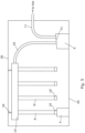
- Figure 3 shows an enlarged view of a portion of the manifold showing the foam core 33 and the solenoid valve 30 which is operable to close the beverage line upon receipt of the signal from the sensor 21 in the connector.
- the valve 30 is a two-way valve which can either direct beverage from the beverage supply 4 towards the dispensing site 5 or towards a bleed line 32 which exits the manifold 19 and is directed towards a drain or storage tank.
- the manifold is provided with a further indicator 27' for providing a further indication when the sensor 21 has generated a signal for closing the beverage line 2.
- the indicator 27' is also a light which changes from green to red when the beverage line 2 is closed. The red light shines onto distal first insulated carrier portion 8.
- the re-set actuator 28 is also operable to re-set the further indicator 27' i.e. to turn the further red light back to green.
- the signal is transferred from the sensor 21 to the valve 30 through a wire 35 via an electronic control unit (ECU) 31 on the manifold.
- ECU 31 sends a signal to the solenoid valve 30 to close the beverage line and also sends a signal to the indicators 27, 27', via a wire 36 in the case of the indicator 27 on the connector 18.
- the re-set actuator button 28 is also connected to the ECU via a wire 37. Actuation of the re-set actuator button 28 sends a signal to the ECU which then sends a signal to the valve 30 to open the beverage line 2 to the bleed line 32 (in the first mode of actuation) or to reconnect the beverage line 2, 2' to allow pumping of water/cleaning fluid (in the second mode of actuation) and also sends a signal to the indicators 27, 27' to deactivate them.
- All of the wires 35, 36 and 37 are bundled within the distal first insulated carrier portion 8.
- the distal first insulated carrier portion 8 also contains a gas line 38 (shown in Figure 2 ) which connectable to a gas supply at one end and connectable to the gas inlet 24 on the keg coupler 22 at its other end.
- the gas line exits the distal first insulated carrier portion 8 before it joins the connector 18.
- Figure 4 shows a schematic representation of a method for replacing a beverage supply.
- a signal is generated and passed along the distal first insulated carrier portion 8 through wire 35 to the ECU 31.
- the ECU 31 Upon receipt of this signal the ECU 31 sends a signal to the solenoid valve 30 causing it to close the beverage line.
- the ECU 31 also sends a signal to the indicator 27' on the manifold 19 and to the indicator 27 on the connector via wire 36 to activate the indicators i.e. to turn the lights from green to red.
- a user entering the beverage supply site can immediately see which beverage supply (storage keg) requires changing by observing the indicators 27, 27'.
- the user will disconnect the depleted beverage supply by removing the connector 18 from the beverage supply and will then connect the connector to a new beverage supply.
- the user will depress the re-set actuator button 28 using a single, short depression which will send a signal to the ECU 31 via wire 37.
- the ECU 31 will send a signal to the solenoid valve 30 which will open the beverage line 2 to the bleed line 32 to discharge any fob from the line.
- the valve closes the bleed line and re-establishes fluid communication along the length of the beverage line so that beverage can be transported to the dispensing site 5.
- the ECU will then send a signal to the indicator 27' on the manifold 19 and to the indicator 27 on the connector via wire to deactivate the indicators i.e. to turn the red lights back to green.
- Figure 5 shows a schematic representation of a second embodiment of a beverage dispense system according to the present invention however, the features shown may also be incorporated into the first embodiment and thus the same numbering is used.
- the length of beverage line 2, 2' (enclosed within the distal first insulated carrier portion) between the distal ends 3, 3' and the manifold 19 is selected such that, when the manifold 19 is suspended from the ceiling 38 of the beverage supply site on brackets 39, the distal ends 3, 3' (and the connectors 18, 18') of the beverage line do not contact the floor 40 of the beverage supply site.
- the cooler 6 has a casing having a slanted top surface 41.
Landscapes
- Devices For Dispensing Beverages (AREA)
Claims (13)
- Getränkeabfüllsystem, das Folgendes umfasst:eine Getränkeleitung (2, 2') zum Transportieren eines Getränks von einer Getränkezufuhr an eine Abfüllstelle (5), wobei die Getränkeleitung ein distales Ende (3, 3') aufweist;ein Bläschendetektionssystem, umfassend:
ein Verbindungselement (18, 18'), das an dem distalen Ende (3, 3') der Getränkeleitung (2, 2') befestigt ist, und das einen Sensor (21) zum Erkennen von Bläschen innerhalb der Getränkeleitung (2, 2') und zum Erzeugen eines Signals zum Schließen der Getränkeleitung (2, 2') aufweist, wenn ein vorbestimmter Pegel von Bläschen detektiert wird, wobei das Verbindungselement (18, 18') mit der Getränkezufuhr (4, 4') verbindbar ist und Folgendes umfasst:einen Verbindungselement-Kühlkreislauf (25), umfassend eine Verbindungselementkühlleitung (29) und eine Verbindungselementkühlrückleitung (26) zum Führen von gekühltem Kühlmedium, wobei die Kühlleitungen in einer Wärmetauschbeziehung mit der Getränkeleitung (2, 2') innerhalb des Verbindungselements (18) zum Kühlen der Getränkeleitung innerhalb des Verbindungselements stehen, undein Rücksetzungsbetätigungselement, das betätigbar ist, um ein Signal zu erzeugen, um die Getränkeleitung erneut zu öffnen, wobei ein erster Modus des Rücksetzungsbetätigungselements bewirkt, dass die Getränkeleitung zu einer Ablassleitung für einen vorbestimmten Zeitraum geöffnet wird;wobei das Bläschendetektionssystem ferner ein Ventil (30) umfasst, das betreibbar ist, um die Getränkeleitung (2, 2') nach Empfang eines Signals von dem Sensor (21) zu schließen,wobei das Getränkeabfüllsystem ferner einen Kühler (6) zum Kühlen des Getränks umfasst, wobei die Getränkeleitung (2, 2') einen ersten Getränkeleitungsabschnitt (7, 7') umfasst, der sich von dem distalen Ende (3, 3') bis zum Kühler (6) innerhalb eines ersten isolierten Trägers erstreckt, wobei
der erste isolierte Träger eine erste Kühlleitung (9) zum Transportieren von gekühltem Kühlmedium durch den ersten isolierten Träger umfasst, um einen Wärmeaustausch zwischen dem Kühlmedium in der ersten Kühlleitung (9) und dem Getränk in dem ersten Getränkeleitungsabschnitt (7, 7') zu ermöglichen. - Getränkeabfüllsystem nach Anspruch 1, wobei die Getränkeleitung (2, 2') ferner einen zweiten Getränkeleitungsabschnitt (10, 10') zum Transportieren eines Getränks von dem Kühler (6) an die Abfüllstelle (5) durch einen zweiten isolierten Träger (11) umfasst, wobei der zweite isolierte Träger (11) eine zweite Kühlleitung (14) zum Transportieren von Kühlmedium durch den zweiten isolierten Träger (11) umfasst, um einen Wärmeaustausch zwischen dem Kühlmedium in der zweiten Kühlleitung (14) und dem Getränk in dem zweiten Kühlleitungsabschnitt (10, 10') zu ermöglichen.
- Getränkeabfüllsystem nach Anspruch 2, wobei die zweite Kühlleitung (14) einen Teil eines zweiten Kühlkreislaufs bildet, wobei der zweite Kühlkreislauf die zweite Kühlleitung (14) umfasst, die sich von dem Kühler (6) durch den zweiten isolierten Träger (11) bis zur Abfüllstelle (5) erstreckt, und eine zweite Rückführleitung (17) umfasst, die sich von der Abfüllstelle (5) durch den zweiten isolierten Träger (11) bis zum Kühler (6) erstreckt.
- Getränkeabfüllsystem nach einem der Ansprüche 1 bis 3, wobei der Kühler (6) ausgelegt ist, um Kühlmedium zum Transport innerhalb der ersten und/oder der zweiten Kühlleitung (9, 14) zu erzeugen.
- Getränkeabfüllsystem nach einem der Ansprüche 1 bis 4, wobei die erste Kühlleitung (9) einen Teil des ersten Kühlkreislaufs bildet, wobei der erste Kühlkreislauf die erste Kühlleitung (9), die sich von dem Kühler (6) durch den ersten isolierten Träger bis zur Getränkezufuhr (4, 4') erstreckt, und eine erste Rückführleitung (16) umfasst, die sich von der Getränkezufuhr (4, 4') durch den ersten isolierten Träger bis zum Kühler (6) erstreckt.
- Getränkeabfüllsystem nach einem der Ansprüche 1 bis 5, das ferner eine Gasleitung (38) umfasst, die mit einer Gaszufuhr verbindbar ist, wobei die Gaszufuhrleitung (38) zumindest teilweise innerhalb des ersten isolierten Trägers umschlossen ist.
- Getränkeabfüllsystem nach einem der vorangegangenen Ansprüche, das ferner einen Verteiler (19) umfasst, durch den die Getränkeleitung (2, 2') hindurchführt, wobei die Länge der Getränkeleitung (2, 2') zwischen dem distalen Ende (3, 3') und dem Verteiler (19) so ausgewählt ist, dass, wenn der Verteiler auf der Wand oder der Decke der Getränkezufuhrstelle angebracht ist, das distale Ende (3, 3') der Getränkeleitung (2, 2') den Boden der Getränkezufuhrstelle nicht berührt.
- Getränkeabfüllsystem nach einem der vorangegangenen Ansprüche, wobei das Verbindungselement (18) über einen Koppler, der mit der Oberseite einer Fasslanze? verbunden ist, und der einen Gassleitungseinlass und einen Getränkeauslass aufweist, mit der Getränkezufuhr (4, 4') verbindbar ist.
- Getränkeabfüllsystem nach einem der vorangegangenen Ansprüche, wobei der Sensor (21) ein optischer Sensor ist, der einen optischen Sender und einen optischen Empfänger aufweist.
- Getränkeabfüllsystem nach einem der vorangegangenen Ansprüche, wobei das Verbindungselement (18) ferner einen Indikator (27) zum Bereitstellen einer Angabe umfasst, wenn der Sensor (21) ein Signal zum Schließen der Getränkeleitung (2, 2') erzeugt hat.
- Getränkeabfüllsystem nach einem der vorangegangenen Ansprüche, wobei das Ventil (30) ein Zweiwegventil ist.
- Getränkeabfüllsystem nach einem der vorangegangenen Ansprüche, das ferner eine elektronische Steuereinheit (31) zum Empfangen des Signals von dem Sensor (21) und als Reaktion auf das Signal von dem Sensor das Senden eines Signals an das Ventil (30) zum Schließen der Getränkeleitung (2, 2') umfasst.
- Getränkeabfüllsystem nach Anspruch 8, wobei das Verbindungselement (18) ferner ein Steckverbindungs- oder Schraubverbindungselement zur Verbindung mit der Getränkezufuhr (5) umfasst.
Applications Claiming Priority (2)
| Application Number | Priority Date | Filing Date | Title |
|---|---|---|---|
| GB1304746.9A GB2511851A (en) | 2013-03-15 | 2013-03-15 | Beverage Dispense System and Method |
| US13/835,179 US20140263433A1 (en) | 2013-03-15 | 2013-03-15 | Beverage Dispense System and Method |
Publications (4)
| Publication Number | Publication Date |
|---|---|
| EP2808678A2 EP2808678A2 (de) | 2014-12-03 |
| EP2808678A3 EP2808678A3 (de) | 2015-03-11 |
| EP2808678B1 EP2808678B1 (de) | 2019-03-13 |
| EP2808678B2 true EP2808678B2 (de) | 2025-06-04 |
Family
ID=50101808
Family Applications (1)
| Application Number | Title | Priority Date | Filing Date |
|---|---|---|---|
| EP14155354.5A Active EP2808678B2 (de) | 2013-03-15 | 2014-02-17 | Getränkeabgabesystem und Verfahren |
Country Status (2)
| Country | Link |
|---|---|
| EP (1) | EP2808678B2 (de) |
| ES (1) | ES2731155T5 (de) |
Families Citing this family (5)
| Publication number | Priority date | Publication date | Assignee | Title |
|---|---|---|---|---|
| CN105651506B (zh) * | 2016-03-23 | 2018-01-30 | 上海交通大学 | 酒矛座测试用的径向力加载装置 |
| US10072962B2 (en) | 2016-07-05 | 2018-09-11 | Ecolab Usa Inc. | Liquid out-of-product alarm system and method |
| US11034569B2 (en) | 2018-02-14 | 2021-06-15 | Taphandles Llc | Cooled beverage dispensing systems and associated devices |
| CA3144190A1 (en) * | 2020-05-25 | 2021-12-23 | Lev Volftsun | Fob system for intelligent flow detection and dispense control |
| JP7522410B2 (ja) * | 2020-09-25 | 2024-07-25 | アサヒビール株式会社 | 液体供給システム、及び液体損失低減方法 |
Citations (6)
| Publication number | Priority date | Publication date | Assignee | Title |
|---|---|---|---|---|
| ES2051619A2 (es) † | 1992-01-20 | 1994-06-16 | Damm Sa | Perfeccionamientos en las instalaciones destinadas al despacho de cerveza de barril. |
| GB2353350A (en) † | 1998-05-15 | 2001-02-21 | Bass Plc | A beverage |
| US20020088823A1 (en) † | 2000-10-19 | 2002-07-11 | Secure Concepts, Ltd. | Distribution control system for dispensing quality liquids |
| GB2411888A (en) † | 2004-03-11 | 2005-09-14 | Stanwell Technic Ltd | Beverage dispensing apparatus |
| EP1690825A2 (de) † | 2005-02-12 | 2006-08-16 | Imi Cornelius (Uk) Limited | Getränkespender |
| JP3847529B2 (ja) † | 2000-06-06 | 2006-11-22 | 麒麟麦酒株式会社 | 飲料供給装置 |
Family Cites Families (5)
| Publication number | Priority date | Publication date | Assignee | Title |
|---|---|---|---|---|
| GB8918596D0 (en) | 1989-08-15 | 1989-09-27 | Bass Plc | The detection of bubbles in flowing liquids |
| NL1002597C2 (nl) * | 1996-03-13 | 1997-09-17 | Epenhuysen Chem Nv | Vat met dompelpijp alsmede dompelpijp voor dat vat. |
| US20050195087A1 (en) * | 2004-03-04 | 2005-09-08 | Thompson Holly R. | Air-in-line detector with warning device |
| DE102006026025A1 (de) | 2005-06-16 | 2006-12-21 | Hans Dirmeier | Leitungselement für flüssige Lebensmittel und Anordnung mit einem Leitungselement |
| NL2001882C2 (nl) | 2008-08-12 | 2010-02-15 | Heineken Supply Chain Bv | Tapkop, tapinrichting en werkwijze voor gebruik van een tapinrichting. |
-
2014
- 2014-02-17 EP EP14155354.5A patent/EP2808678B2/de active Active
- 2014-02-17 ES ES14155354T patent/ES2731155T5/es active Active
Patent Citations (6)
| Publication number | Priority date | Publication date | Assignee | Title |
|---|---|---|---|---|
| ES2051619A2 (es) † | 1992-01-20 | 1994-06-16 | Damm Sa | Perfeccionamientos en las instalaciones destinadas al despacho de cerveza de barril. |
| GB2353350A (en) † | 1998-05-15 | 2001-02-21 | Bass Plc | A beverage |
| JP3847529B2 (ja) † | 2000-06-06 | 2006-11-22 | 麒麟麦酒株式会社 | 飲料供給装置 |
| US20020088823A1 (en) † | 2000-10-19 | 2002-07-11 | Secure Concepts, Ltd. | Distribution control system for dispensing quality liquids |
| GB2411888A (en) † | 2004-03-11 | 2005-09-14 | Stanwell Technic Ltd | Beverage dispensing apparatus |
| EP1690825A2 (de) † | 2005-02-12 | 2006-08-16 | Imi Cornelius (Uk) Limited | Getränkespender |
Non-Patent Citations (7)
| Title |
|---|
| "Brewing Green 2013" published by the British Beer & Pub Association † |
| Article from "the Guardian" confirming use of SmartDispense system 2012. † |
| CAD drawing of the optical sensor included in the torpedo connector † |
| CAD drawing of the torpedo connecto † |
| Propel Newsletter of 14.03.2016, from www.proDelinfonews.com † |
| Radzievich, Nicole "A cool idea for drinkers..", published on 09.08.2011 † |
| Schematic drawing of the Friio-8/SmartDispense system † |
Also Published As
| Publication number | Publication date |
|---|---|
| EP2808678A2 (de) | 2014-12-03 |
| EP2808678A3 (de) | 2015-03-11 |
| EP2808678B1 (de) | 2019-03-13 |
| ES2731155T5 (en) | 2025-08-28 |
| ES2731155T3 (es) | 2019-11-14 |
Similar Documents
| Publication | Publication Date | Title |
|---|---|---|
| US20140263433A1 (en) | Beverage Dispense System and Method | |
| EP2808678B2 (de) | Getränkeabgabesystem und Verfahren | |
| US11225406B2 (en) | Beverage dispense systems and beverage coolers | |
| AU2016101916A4 (en) | A beverage dispenser | |
| US10392238B2 (en) | Method and system for cleaning beverage dispensing systems | |
| EP0880465B1 (de) | Temperaturreguliervorrichtung für flüssigkeiten | |
| US7552593B2 (en) | Supplying draught beverages | |
| US20080251536A1 (en) | Bottled beverage dispenser | |
| GB2511851A (en) | Beverage Dispense System and Method | |
| US20210122622A1 (en) | Remote controlled beverage dispensing system | |
| EP1690825A2 (de) | Getränkespender | |
| EP1767489A2 (de) | Getränkespender mit Spüleinrichtung | |
| WO1999037578A1 (en) | Beverage dispenser with cooling unit and python | |
| GB2505903A (en) | Dispensing beverage left in dispense lines using pressurised gas | |
| WO1996027552A1 (en) | Refrigerated drinks dispenser | |
| AU2021240295A1 (en) | A beverage dispenser | |
| US20250326627A1 (en) | Beverage dispensing nozzle | |
| WO1990000517A1 (en) | Temperature control systems | |
| WO2009133346A1 (en) | Apparatus for cooling beverages | |
| WO2020070226A1 (en) | Beverage distribution line with cooled pump | |
| TH70399A (th) | เครื่องจ่ายเครื่องดื่ม |
Legal Events
| Date | Code | Title | Description |
|---|---|---|---|
| PUAI | Public reference made under article 153(3) epc to a published international application that has entered the european phase |
Free format text: ORIGINAL CODE: 0009012 |
|
| 17P | Request for examination filed |
Effective date: 20140217 |
|
| AK | Designated contracting states |
Kind code of ref document: A2 Designated state(s): AL AT BE BG CH CY CZ DE DK EE ES FI FR GB GR HR HU IE IS IT LI LT LU LV MC MK MT NL NO PL PT RO RS SE SI SK SM TR |
|
| AX | Request for extension of the european patent |
Extension state: BA ME |
|
| PUAL | Search report despatched |
Free format text: ORIGINAL CODE: 0009013 |
|
| AK | Designated contracting states |
Kind code of ref document: A3 Designated state(s): AL AT BE BG CH CY CZ DE DK EE ES FI FR GB GR HR HU IE IS IT LI LT LU LV MC MK MT NL NO PL PT RO RS SE SI SK SM TR |
|
| AX | Request for extension of the european patent |
Extension state: BA ME |
|
| RIC1 | Information provided on ipc code assigned before grant |
Ipc: G01N 29/00 20060101AFI20150130BHEP Ipc: B67D 1/12 20060101ALI20150130BHEP Ipc: B67D 1/08 20060101ALN20150130BHEP |
|
| R17P | Request for examination filed (corrected) |
Effective date: 20150812 |
|
| RBV | Designated contracting states (corrected) |
Designated state(s): AL AT BE BG CH CY CZ DE DK EE ES FI FR GB GR HR HU IE IS IT LI LT LU LV MC MK MT NL NO PL PT RO RS SE SI SK SM TR |
|
| 17Q | First examination report despatched |
Effective date: 20160621 |
|
| STAA | Information on the status of an ep patent application or granted ep patent |
Free format text: STATUS: EXAMINATION IS IN PROGRESS |
|
| GRAP | Despatch of communication of intention to grant a patent |
Free format text: ORIGINAL CODE: EPIDOSNIGR1 |
|
| STAA | Information on the status of an ep patent application or granted ep patent |
Free format text: STATUS: GRANT OF PATENT IS INTENDED |
|
| RIC1 | Information provided on ipc code assigned before grant |
Ipc: G01N 29/00 20060101AFI20180830BHEP Ipc: B67D 1/08 20060101ALN20180830BHEP Ipc: B67D 1/12 20060101ALI20180830BHEP |
|
| INTG | Intention to grant announced |
Effective date: 20180920 |
|
| GRAS | Grant fee paid |
Free format text: ORIGINAL CODE: EPIDOSNIGR3 |
|
| GRAA | (expected) grant |
Free format text: ORIGINAL CODE: 0009210 |
|
| STAA | Information on the status of an ep patent application or granted ep patent |
Free format text: STATUS: THE PATENT HAS BEEN GRANTED |
|
| AK | Designated contracting states |
Kind code of ref document: B1 Designated state(s): AL AT BE BG CH CY CZ DE DK EE ES FI FR GB GR HR HU IE IS IT LI LT LU LV MC MK MT NL NO PL PT RO RS SE SI SK SM TR |
|
| REG | Reference to a national code |
Ref country code: GB Ref legal event code: FG4D |
|
| REG | Reference to a national code |
Ref country code: CH Ref legal event code: EP Ref country code: AT Ref legal event code: REF Ref document number: 1108390 Country of ref document: AT Kind code of ref document: T Effective date: 20190315 |
|
| REG | Reference to a national code |
Ref country code: IE Ref legal event code: FG4D |
|
| REG | Reference to a national code |
Ref country code: DE Ref legal event code: R096 Ref document number: 602014042669 Country of ref document: DE |
|
| REG | Reference to a national code |
Ref country code: NL Ref legal event code: FP |
|
| REG | Reference to a national code |
Ref country code: LT Ref legal event code: MG4D |
|
| PG25 | Lapsed in a contracting state [announced via postgrant information from national office to epo] |
Ref country code: SE Free format text: LAPSE BECAUSE OF FAILURE TO SUBMIT A TRANSLATION OF THE DESCRIPTION OR TO PAY THE FEE WITHIN THE PRESCRIBED TIME-LIMIT Effective date: 20190313 Ref country code: LT Free format text: LAPSE BECAUSE OF FAILURE TO SUBMIT A TRANSLATION OF THE DESCRIPTION OR TO PAY THE FEE WITHIN THE PRESCRIBED TIME-LIMIT Effective date: 20190313 Ref country code: NO Free format text: LAPSE BECAUSE OF FAILURE TO SUBMIT A TRANSLATION OF THE DESCRIPTION OR TO PAY THE FEE WITHIN THE PRESCRIBED TIME-LIMIT Effective date: 20190613 Ref country code: FI Free format text: LAPSE BECAUSE OF FAILURE TO SUBMIT A TRANSLATION OF THE DESCRIPTION OR TO PAY THE FEE WITHIN THE PRESCRIBED TIME-LIMIT Effective date: 20190313 |
|
| PG25 | Lapsed in a contracting state [announced via postgrant information from national office to epo] |
Ref country code: BG Free format text: LAPSE BECAUSE OF FAILURE TO SUBMIT A TRANSLATION OF THE DESCRIPTION OR TO PAY THE FEE WITHIN THE PRESCRIBED TIME-LIMIT Effective date: 20190613 Ref country code: LV Free format text: LAPSE BECAUSE OF FAILURE TO SUBMIT A TRANSLATION OF THE DESCRIPTION OR TO PAY THE FEE WITHIN THE PRESCRIBED TIME-LIMIT Effective date: 20190313 Ref country code: RS Free format text: LAPSE BECAUSE OF FAILURE TO SUBMIT A TRANSLATION OF THE DESCRIPTION OR TO PAY THE FEE WITHIN THE PRESCRIBED TIME-LIMIT Effective date: 20190313 Ref country code: HR Free format text: LAPSE BECAUSE OF FAILURE TO SUBMIT A TRANSLATION OF THE DESCRIPTION OR TO PAY THE FEE WITHIN THE PRESCRIBED TIME-LIMIT Effective date: 20190313 Ref country code: GR Free format text: LAPSE BECAUSE OF FAILURE TO SUBMIT A TRANSLATION OF THE DESCRIPTION OR TO PAY THE FEE WITHIN THE PRESCRIBED TIME-LIMIT Effective date: 20190614 |
|
| REG | Reference to a national code |
Ref country code: AT Ref legal event code: MK05 Ref document number: 1108390 Country of ref document: AT Kind code of ref document: T Effective date: 20190313 |
|
| PG25 | Lapsed in a contracting state [announced via postgrant information from national office to epo] |
Ref country code: CZ Free format text: LAPSE BECAUSE OF FAILURE TO SUBMIT A TRANSLATION OF THE DESCRIPTION OR TO PAY THE FEE WITHIN THE PRESCRIBED TIME-LIMIT Effective date: 20190313 Ref country code: IT Free format text: LAPSE BECAUSE OF FAILURE TO SUBMIT A TRANSLATION OF THE DESCRIPTION OR TO PAY THE FEE WITHIN THE PRESCRIBED TIME-LIMIT Effective date: 20190313 Ref country code: SK Free format text: LAPSE BECAUSE OF FAILURE TO SUBMIT A TRANSLATION OF THE DESCRIPTION OR TO PAY THE FEE WITHIN THE PRESCRIBED TIME-LIMIT Effective date: 20190313 Ref country code: AL Free format text: LAPSE BECAUSE OF FAILURE TO SUBMIT A TRANSLATION OF THE DESCRIPTION OR TO PAY THE FEE WITHIN THE PRESCRIBED TIME-LIMIT Effective date: 20190313 Ref country code: PT Free format text: LAPSE BECAUSE OF FAILURE TO SUBMIT A TRANSLATION OF THE DESCRIPTION OR TO PAY THE FEE WITHIN THE PRESCRIBED TIME-LIMIT Effective date: 20190713 Ref country code: EE Free format text: LAPSE BECAUSE OF FAILURE TO SUBMIT A TRANSLATION OF THE DESCRIPTION OR TO PAY THE FEE WITHIN THE PRESCRIBED TIME-LIMIT Effective date: 20190313 Ref country code: RO Free format text: LAPSE BECAUSE OF FAILURE TO SUBMIT A TRANSLATION OF THE DESCRIPTION OR TO PAY THE FEE WITHIN THE PRESCRIBED TIME-LIMIT Effective date: 20190313 |
|
| REG | Reference to a national code |
Ref country code: ES Ref legal event code: FG2A Ref document number: 2731155 Country of ref document: ES Kind code of ref document: T3 Effective date: 20191114 |
|
| PG25 | Lapsed in a contracting state [announced via postgrant information from national office to epo] |
Ref country code: SM Free format text: LAPSE BECAUSE OF FAILURE TO SUBMIT A TRANSLATION OF THE DESCRIPTION OR TO PAY THE FEE WITHIN THE PRESCRIBED TIME-LIMIT Effective date: 20190313 Ref country code: PL Free format text: LAPSE BECAUSE OF FAILURE TO SUBMIT A TRANSLATION OF THE DESCRIPTION OR TO PAY THE FEE WITHIN THE PRESCRIBED TIME-LIMIT Effective date: 20190313 |
|
| REG | Reference to a national code |
Ref country code: DE Ref legal event code: R026 Ref document number: 602014042669 Country of ref document: DE |
|
| PLBI | Opposition filed |
Free format text: ORIGINAL CODE: 0009260 |
|
| PG25 | Lapsed in a contracting state [announced via postgrant information from national office to epo] |
Ref country code: IS Free format text: LAPSE BECAUSE OF FAILURE TO SUBMIT A TRANSLATION OF THE DESCRIPTION OR TO PAY THE FEE WITHIN THE PRESCRIBED TIME-LIMIT Effective date: 20190713 Ref country code: AT Free format text: LAPSE BECAUSE OF FAILURE TO SUBMIT A TRANSLATION OF THE DESCRIPTION OR TO PAY THE FEE WITHIN THE PRESCRIBED TIME-LIMIT Effective date: 20190313 |
|
| PLAX | Notice of opposition and request to file observation + time limit sent |
Free format text: ORIGINAL CODE: EPIDOSNOBS2 |
|
| 26 | Opposition filed |
Opponent name: DFX TECHNOLOGY LIMITED Effective date: 20191213 |
|
| PG25 | Lapsed in a contracting state [announced via postgrant information from national office to epo] |
Ref country code: DK Free format text: LAPSE BECAUSE OF FAILURE TO SUBMIT A TRANSLATION OF THE DESCRIPTION OR TO PAY THE FEE WITHIN THE PRESCRIBED TIME-LIMIT Effective date: 20190313 |
|
| PG25 | Lapsed in a contracting state [announced via postgrant information from national office to epo] |
Ref country code: SI Free format text: LAPSE BECAUSE OF FAILURE TO SUBMIT A TRANSLATION OF THE DESCRIPTION OR TO PAY THE FEE WITHIN THE PRESCRIBED TIME-LIMIT Effective date: 20190313 |
|
| PG25 | Lapsed in a contracting state [announced via postgrant information from national office to epo] |
Ref country code: TR Free format text: LAPSE BECAUSE OF FAILURE TO SUBMIT A TRANSLATION OF THE DESCRIPTION OR TO PAY THE FEE WITHIN THE PRESCRIBED TIME-LIMIT Effective date: 20190313 |
|
| PLBB | Reply of patent proprietor to notice(s) of opposition received |
Free format text: ORIGINAL CODE: EPIDOSNOBS3 |
|
| REG | Reference to a national code |
Ref country code: DE Ref legal event code: R119 Ref document number: 602014042669 Country of ref document: DE |
|
| REG | Reference to a national code |
Ref country code: CH Ref legal event code: PL |
|
| REG | Reference to a national code |
Ref country code: BE Ref legal event code: MM Effective date: 20200229 |
|
| PG25 | Lapsed in a contracting state [announced via postgrant information from national office to epo] |
Ref country code: LU Free format text: LAPSE BECAUSE OF NON-PAYMENT OF DUE FEES Effective date: 20200217 Ref country code: MC Free format text: LAPSE BECAUSE OF FAILURE TO SUBMIT A TRANSLATION OF THE DESCRIPTION OR TO PAY THE FEE WITHIN THE PRESCRIBED TIME-LIMIT Effective date: 20190313 |
|
| PG25 | Lapsed in a contracting state [announced via postgrant information from national office to epo] |
Ref country code: LI Free format text: LAPSE BECAUSE OF NON-PAYMENT OF DUE FEES Effective date: 20200229 Ref country code: CH Free format text: LAPSE BECAUSE OF NON-PAYMENT OF DUE FEES Effective date: 20200229 |
|
| PG25 | Lapsed in a contracting state [announced via postgrant information from national office to epo] |
Ref country code: DE Free format text: LAPSE BECAUSE OF NON-PAYMENT OF DUE FEES Effective date: 20200901 |
|
| PG25 | Lapsed in a contracting state [announced via postgrant information from national office to epo] |
Ref country code: BE Free format text: LAPSE BECAUSE OF NON-PAYMENT OF DUE FEES Effective date: 20200229 |
|
| PG25 | Lapsed in a contracting state [announced via postgrant information from national office to epo] |
Ref country code: MT Free format text: LAPSE BECAUSE OF FAILURE TO SUBMIT A TRANSLATION OF THE DESCRIPTION OR TO PAY THE FEE WITHIN THE PRESCRIBED TIME-LIMIT Effective date: 20190313 Ref country code: CY Free format text: LAPSE BECAUSE OF FAILURE TO SUBMIT A TRANSLATION OF THE DESCRIPTION OR TO PAY THE FEE WITHIN THE PRESCRIBED TIME-LIMIT Effective date: 20190313 |
|
| PG25 | Lapsed in a contracting state [announced via postgrant information from national office to epo] |
Ref country code: MK Free format text: LAPSE BECAUSE OF FAILURE TO SUBMIT A TRANSLATION OF THE DESCRIPTION OR TO PAY THE FEE WITHIN THE PRESCRIBED TIME-LIMIT Effective date: 20190313 |
|
| PLAB | Opposition data, opponent's data or that of the opponent's representative modified |
Free format text: ORIGINAL CODE: 0009299OPPO |
|
| REG | Reference to a national code |
Ref country code: CH Ref legal event code: PK Free format text: BERICHTIGUNGEN |
|
| REG | Reference to a national code |
Ref country code: CH Ref legal event code: PK Free format text: BERICHTIGUNGEN |
|
| RIC2 | Information provided on ipc code assigned after grant |
Ipc: B67D 1/08 20060101ALN20220712BHEP Ipc: B67D 1/12 20060101ALI20220712BHEP Ipc: G01N 29/00 20060101AFI20220712BHEP |
|
| R26 | Opposition filed (corrected) |
Opponent name: DFX TECHNOLOGY LIMITED Effective date: 20191213 |
|
| RIC2 | Information provided on ipc code assigned after grant |
Ipc: B67D 1/08 20060101ALN20220726BHEP Ipc: B67D 1/12 20060101ALI20220726BHEP Ipc: G01N 29/00 20060101AFI20220726BHEP |
|
| APAH | Appeal reference modified |
Free format text: ORIGINAL CODE: EPIDOSCREFNO |
|
| APBM | Appeal reference recorded |
Free format text: ORIGINAL CODE: EPIDOSNREFNO |
|
| APBP | Date of receipt of notice of appeal recorded |
Free format text: ORIGINAL CODE: EPIDOSNNOA2O |
|
| APBM | Appeal reference recorded |
Free format text: ORIGINAL CODE: EPIDOSNREFNO |
|
| APBP | Date of receipt of notice of appeal recorded |
Free format text: ORIGINAL CODE: EPIDOSNNOA2O |
|
| APBQ | Date of receipt of statement of grounds of appeal recorded |
Free format text: ORIGINAL CODE: EPIDOSNNOA3O |
|
| APBQ | Date of receipt of statement of grounds of appeal recorded |
Free format text: ORIGINAL CODE: EPIDOSNNOA3O |
|
| P01 | Opt-out of the competence of the unified patent court (upc) registered |
Effective date: 20230524 |
|
| APBU | Appeal procedure closed |
Free format text: ORIGINAL CODE: EPIDOSNNOA9O |
|
| PGFP | Annual fee paid to national office [announced via postgrant information from national office to epo] |
Ref country code: NL Payment date: 20250121 Year of fee payment: 12 |
|
| PGFP | Annual fee paid to national office [announced via postgrant information from national office to epo] |
Ref country code: IE Payment date: 20250220 Year of fee payment: 12 |
|
| PGFP | Annual fee paid to national office [announced via postgrant information from national office to epo] |
Ref country code: FR Payment date: 20250221 Year of fee payment: 12 |
|
| PGFP | Annual fee paid to national office [announced via postgrant information from national office to epo] |
Ref country code: GB Payment date: 20250219 Year of fee payment: 12 |
|
| PUAH | Patent maintained in amended form |
Free format text: ORIGINAL CODE: 0009272 |
|
| STAA | Information on the status of an ep patent application or granted ep patent |
Free format text: STATUS: PATENT MAINTAINED AS AMENDED |
|
| 27A | Patent maintained in amended form |
Effective date: 20250604 |
|
| AK | Designated contracting states |
Kind code of ref document: B2 Designated state(s): AL AT BE BG CH CY CZ DE DK EE ES FI FR GB GR HR HU IE IS IT LI LT LU LV MC MK MT NL NO PL PT RO RS SE SI SK SM TR |
|
| REG | Reference to a national code |
Ref country code: DE Ref legal event code: R102 Ref document number: 602014042669 Country of ref document: DE |
|
| PGFP | Annual fee paid to national office [announced via postgrant information from national office to epo] |
Ref country code: ES Payment date: 20250331 Year of fee payment: 12 |
|
| REG | Reference to a national code |
Ref country code: NL Ref legal event code: FP |
|
| REG | Reference to a national code |
Ref country code: ES Ref legal event code: DC2A Ref document number: 2731155 Country of ref document: ES Kind code of ref document: T5 Effective date: 20250828 |